

Page 1
Cinema Pro JR-K5
Operations Manual
Page 2

BEFORE YOU START, READ THESE WARNINGS
1) NEVER PLUG POWER DEVICES OTHER THAN THOSE SUPPLIED BY
VARIZOOM INTO THE SYSTEM. ONLY USE VARIZOOM POWER SOURCES
AND CABLES. USING DIFFERENT POWER COMPONENTS CAN LEAD TO
SEVERE DAMAGE TO THE HEAD AND EVEN THE CAMERA. THIS TYPE
OF DAMAGE IS NOT COVERED UNDER WARRANTY.
2) DO NOT MODIFY THE SUPPLIED CABLES OR ATTEMPT TO
DISASSEMBLE THE HEAD.
3) LENS CONTROL CABLES MUST ONLY BE PLUGGED INTO THE
SPECIFIED INPUT JACK ON THE LENS ITSELF – NEVER PLUG A 12-PIN
CONNECTOR ON A VARIZOOM LENS CONTROL CABLE INTO THE 12PIN
JACK ON THE CAMERA BODY. WHEN IN DOUBT, CONSULT VARIZOOM
OR YOUR LENS MANUAL.
4) THE ADVANCED CONTROLLER DOES NOT REQUIRE SEPARATE POWER,
IT RECEIVES POWER THROUGH THE GREEN-CODED CONTROL CABLE
THAT CONNECTS TO THE HEAD. THE “AUX” POWER JACK ON THE
ADVANCED CONTROLLER IS ONLY UTILIZED IN WIRELESS
CONFIGURATIONS AND SHOULD ONLY BE CONNECTED TO A
VARIZOOM POWER SUPPLY.
5) DO NOT OPERATE THE HEAD WITH AN UNBALANCED LOAD (i.e., with
the camera’s weight extremely off-center either horizontally or
vertically).
6) DO NOT GET THE SYSTEM WET – IT IS NOT WATERPROOF.
7) ALWAYS MAKE SURE YOUR LENS AND POWER CABLES HAVE ENOUGH
SLACK RUNNING THROUGH THE TILT AXIS TO PREVENT TWISTING
AND TEARING OF THE CABLES.
8) MAKE SURE YOUR LENS CLEARS THE BASE OF THE HEAD WHEN
TILTING. IF THE LENS DOES NOT CLEAR THE BASE, SET SOFT LIMITS
(SECTION 7) TO PREVENT THE LENS FROM STRIKING THE BASE OF
THE HEAD WHEN TILTING.
9) WHEN USING THE CP JR’s ONBOARD LENS CONTROLS TO CONTROL
YOUR CAMERA, ALWAYS POWER THE CAMERA UP LAST. OTHERWISE,
THE RECORD START/STOP FEATURE MAY FALL OUT OF SYNC. TO
AVOID THIS ISSUE, JUST MAKE SURE TO CONNECT XLR POWER TO
THE HEAD BEFORE YOU TURN YOUR CAMERA ON.
Page 3

General Description
The CinemaPro JR is a lightweight, two-axis motion control head for film
and video cameras. It has a wide variety of operating modes: manual operation
from joystick, motion control style record and playback, “go to mark” preset
framing*. Software upgrade options are also available for additional features
such as intervalometer, camera sync, PC data share, and additional recorded
takes and mark points.
The Cinema Pro JR’s optional advanced Controller can give the user all
input and programming capabilities and has a joystick for pan & tilt control.
The Advanced Controller also works in concert with two optional control input
devices: Pan Bars for broadcast-style operation or Hand Wheels for cinemastyle operation.
The Jibstick remote is a simpler, less expensive controller designed for
one-man jib operation. The jibstick only offers joystick pan & tilt with
smoothing and speed control.
The Cinema Pro JR’s lens interface controls zoom and focus. It handles
several control signals: RS-232 for Fujinon digital lenses or Varizoom (TOC)
motor drives, RS-422 for Canon digital lenses or Preston motor drives, position
or speed based analog, pulse width type RC servos, and LANC.
*Go to marks and presets are only available when using the advanced controller.
Page 4
1. Basic Setup
-Secure the head to crane, tripod, or solid mounting beam
-Plug the FACTORY POWER SUPPLY into AC mains
-Connect XLR cable between head and FACTORY POWER
SUPPLY
-Plug green control cable into the head and the jack marked
“CTRL” on the Advanced Controller (or Jibstick, if applicable)
-If applicable, connect camera power (red) and lens control cables
(orange) and route the cables through the tilt axis port hole to connect to your camera
-Make sure to turn camera power on as the LAST step.
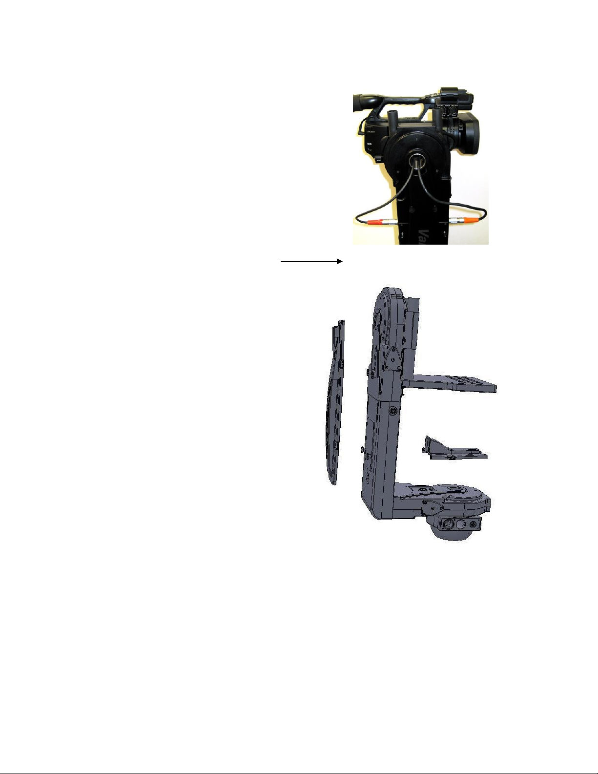
Feeding External Cables through the Head
In some cases, you will need to feed video or other
cables through the head. To do so, simply remove the
cable covers (pictured at right, covers may differ
slightly in appearance). 4 screws secure the long
vertical cable cover, while only 2 screws secure the
short horizontal cover. Run the cables through the pan
base and tilt arm with enough slack, and reattach the
cable covers.
If using the TOC system
Connect the TOC 3A (3 axis lens drive box) between the
orange 16-PIN lens control connector located on the
head, and the grey “control” connector located on the
TOC 3A. Connect the Lens drive motors to the
appropriate connection according to their function (zoom, focus, iris)
Page 5
Balance the Camera – Although the head will hold position very well, it operates best when the camera
Center of Mass
is balanced on the mounting platform. With heavier cameras, it is essential, as an out-of-balance load
will cause the servos to constantly fight to hold position. Make sure that the motor power is turned off
before balancing. This will allow you to move the tilt axis by hand. To balance the camera
horizontally, you need to place the camera’s front-to-back center of mass at the center of the mounting
platform slot. You can do this by trial and error, sliding the camera front-to-back on the mounting
platform until it stays level. The simplest accurate way to find the camera’s center of mass is to lay a
pencil/pen on a table and try to balance the camera on it front-to-back. The spot on the camera where
it comes closest to balancing on the pencil is the center of mass. Place the camera’s center of mass at
the center of the mounting slot and secure the camera with mounting screws (2 if possible). When
horizontally balanced, the platform should stay level.
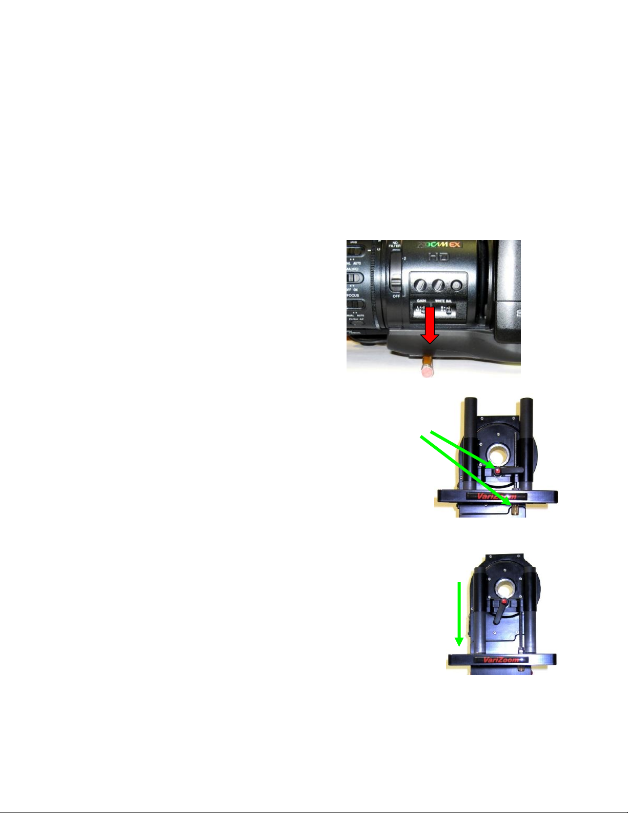
To get the vertical balance right, raise or lower the platform to get the
camera’s vertical center of mass located on the center of tilt rotation. To
adjust, loosen the platform locking lever about ½ turn. Turn the black knob
on the underside of the platform to precisely raise or lower it – you can use
a hex key. Try to get the camera’s center of mass right on the center of tilt
rotation. Rotate the platform to various angles and adjust until it holds
position at any angle. If it falls down, you need to adjust the platform
upward. If it drifts upward, you need to lower the platform. When balance
is achieved, tighten the platform locking lever.
After all connections have been made and the camera is balanced, the head is
ready to be powered up.
Connect the power supply to AC power. Plug in the green communication
connector to the head, and the other end to the jibstick. The jibstick should now power up. Once the
Sync light is illuminated, you may then turn on the motor power switch.
Page 6
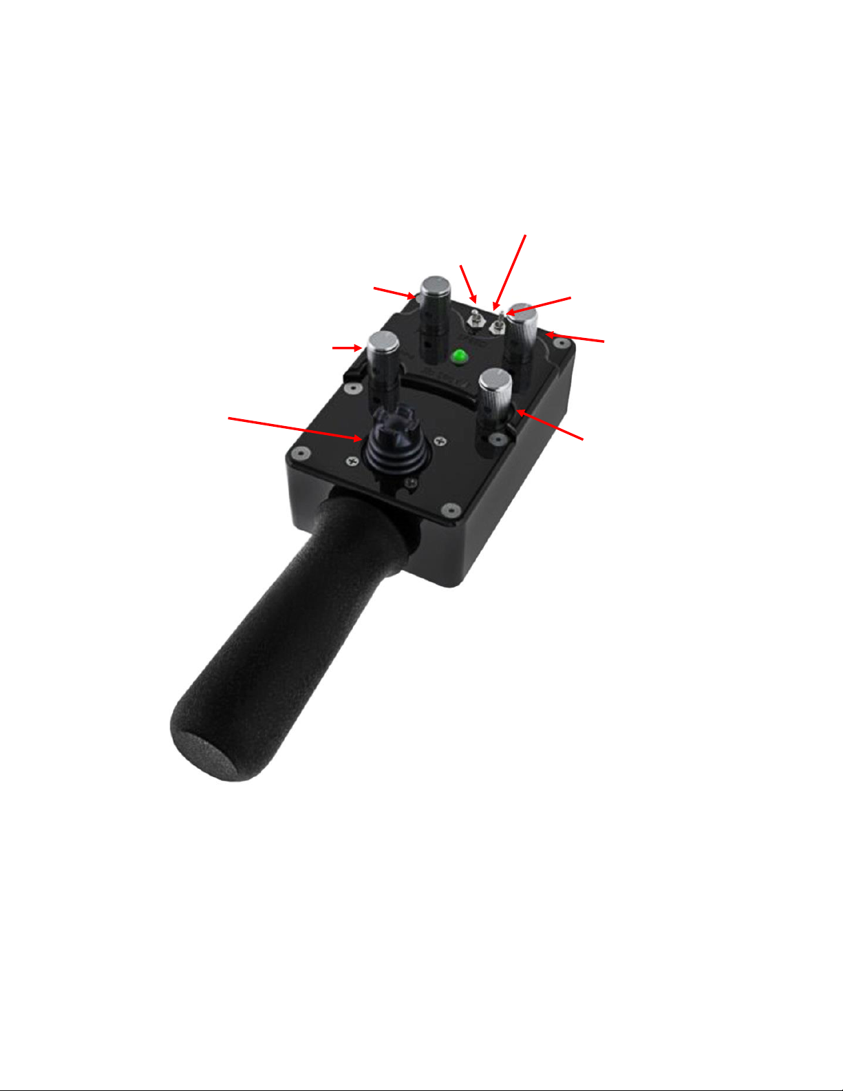
Joystick deadband
2. Jibstick layout and functions
Pan Speed
Pan direction
Communication Connector
Tilt direction
Tilt Speed
Smoothing
Pan/Tilt
Control joystick
Communication connector (Green)- Connect this to the communication cable, and connect the other
end of the communication cable to the green connector on the CinemaPro Head. This cable runs
communication as well as power, so make sure that there is XLR power connected to the CinemaPro
Pan direction and Tilt direction- Reverses the response direction for each axis
Page 7

Joystick for pan and tilt operation- Move the joystick in the direction you wish the head to move. The
response direction can be changed with the response direction switches.
Smoothing- Adjusts the amount of smoothing for both the pan and tilt axes. The higher the smoothing
is set the more “delay” there will be in response to the joystick.
Pan speed and Tilt Speed- Adjusts the maximum speed for the pan motor and tilt motor.
Deadband- Adjusts the amount the joystick must be moved before pan and tilt will respond.
3. Troubleshooting
No Response from head
1) Make sure that the motor power switch is turned on, and the light above it is green.
2) Check to make sure that there aren’t any soft limits set too close together. Disable all soft limits, and
then try again.
3) Power down the system, unplug the XLR connector, wait for a few seconds, re-plug everything back
in, power it back up, then try again.
Pan and Tilt moves too slowly or PanBar range is limited
1) Check both speed settings. If the speed is dialed too slowly it will appear to have no response at all.
Head is “jerky” or too responsive
1) Turn down motor speed.
5) If you have been using the advanced controller, check to make sure that the servo tuning in the
“tuning” menu is set to the factory setting. Selecting “reset all” will return this to the factory preset.
Note: When the jibstick is plugged into the head, it will default to the servo tuning of the last
advanced controller that used with the head.
My jib or crane sways, swims, moves around when the head is rotating
1) This is a problem of imbalance in rotational inertia. If the jib moves when panning, you need to
attach the optional counterweight. If the jib move around when tilting, you need to adjust the
vertical balance (adjust the camera platform until the camera’s center of gravity is on the center
of tilt rotation.
Page 8

4. Options and Specs
Additional Software- The controller can be upgraded to have more position marks, intervalometer
mode, and additional recorded moves.
Additional Head options-
The Head can be fitted with either a 100mm half ball or Mitchell mount. A Mitchell ring adapter is
available for old style Mitchell mount.
An adapter is also available to adapt Mitchell mount to Jimmy Jib style mount.
Wireless control is available, and operates up to ¼ mile. (1 mile with line of sight).
Additional controller cables are available in 50’, 100’, or 150’ increments. A coupler is available to join
the cables, or we will make a cable of any reasonable length as a custom item on request.
Head XLR power cables are available in standard 30’ or 75’ increments, or longer as a custom item on
request.
External Lens Drive Motors available for separate purchase
Page 9

Specs-
Head construction: Primarily Aluminum, with carbon fiber platform rails and some stainless steel, steel,
brass, bronze and delrin components
Height: 20.5”
Width: 11.3”
Depth: 6”
Weight: 13lbs
Camera weight limit: 35lbs
Maximum speed: 130 deg/sec (limited for optimal performance)
Power Supply (included): 24VDC, 5A
Head Power Requirements: 24 VDC regulated, 120 watts max
WARNING: Do not connect the head to any power supply other than the one supplied. If you must
power the head another way, make sure you clear it with VariZoom first.
Page 10

Connectors-
Head Base connectors
Controller - 7pin LEMO (green)
XLR 4-pin Head/Camera Power
Passageway for external cables (video, lens control, etc.)
Head Top connectors
Lens Control Out to camera/lens/lens drive - 16pin LEMO (orange)
Camera Power Out - 2pin LEMO (red)
Controller connectors
CTRL - 7Pin LEMO – Head control cable (green)
SERIAL - 8pin LEMO – TOC or Preston Lens Drive Hand Units (gray)
ANALOG - 5pin LEMO – Pan Bars zoom & focus controls (white)
Page 11

Jib Counterweight Option
(1)
(2)
Some lightweight jibs may not have enough mass to neutralize the high acceleration and torque of the
CP Jr head. If the motion of the head causes your jib to sway from side to side in a way you want to
eliminate, we have a counterweight option that will effectively eliminate the problem.
Heavier jibs will not be affected much, and the effect is only significant during sudden moves. Adding
our counterweight to the CP Jr balances out the rotational inertia so even lightweight jibs will not be
susceptible to the swaying effect caused by sudden moves.
Attaching the counterweight is simple. Before
attaching the counterweight, fix the head to your
jib.
(1) Start by attaching the interface plate to the
head with the 4 small screws (supplied). Now fix
the support arm to the interface plate using the
supplied thumbscrews, lockwashers, and flat
washers. Put the flat washers between the
support arm and the lockwashers to prevent
scratching. Tighten the thumbscrews thoroughly.
(2) Now attach the square weight to the support arm,
using the same type of thumbscrews, lockwashers and
washers. Tighten the thumbscrews thoroughly.
The counterweight adds about 7 lbs total weight to the
system, so if you don’t need it, try operating without it
first. Also note that some swaying may be caused by the
camera platform being out of vertical balance – remedy
this by adjusting the camera platform up or down so the
camera’s center of mass is on the center of tilt rotation.
Page 12

Appendix
24VDC Power Supply Connector
1) Power Supply Connector – XLR 4-pin Female
Pin Function Wire Color
1 N.C.
2 CP JR Neg. Black & Green
3 CP JR Pos. White & Red
4 N.C.
* 2) Optional XLR Y-adapter for running head AND camera power through single XLR extension
Y-1 “Camera” Power Input Male XLR Connector
Pin Function
1 Camera Neg.
2 N.C
3 N.C.
4 Camera Pos.
Y-2 “Head” Power Input Male XLR Connector
Pin Function
1 N.C.
2 CP JR Neg.
3 CP JR Pos.
4 N.C.
Y-Single Female XLR Output Connector (combines Camera & Head Power into one XLR cable run
– connect to 30’ XLR extension that plugs into CP JR head)
Pin Function
1 Camera Neg.
2 CP JR Neg.
3 CP JR Pos.
4 Camera Pos.
Page 13

CP JR Head - Base Connectors
1) Head Control Connector (Green) – LEMO EGG1B307CLL
Pin Function Wire Color (Cable)
1 Common Brown
2 RS-422 RXD Red
3 RS-422 RXD! Orange
4 RS-422 TXD Yellow
5 RS-422 TXD! Green
6 24 VDC + Blue Power to Remote or Jibstick
7 24 VDC - Violet Power to Remote or Jibstick
2) Power Input Connector – XLR 4-pin Male
Pin Function Wire Color
1 Camera Neg. Black
2 Cinema Pro Neg. White
3 Cinema Pro Pos. Red
4 Camera Pos. Green
*** WARNING: DO NOT POWER THE CINEMAPRO JR WITH ANYTHING OTHER THAN
THE INCLUDED FACTORY POWER SUPPLY OR YOUR WARRANTY MAY BE VOIDED.
THE UNIT MAY BE SEVERELY DAMAGED AND CAUSE DAMAGE TO YOUR CAMERA IF
YOU USE A NON-APPROVED POWER SUPPLY. IF YOU MUST POWER IT USING A
BATTERY SYSTEM, MAKE SURE THE SETUP IS APPROVED BY VARIZOOM AND
EXECUTED BY A QUALIFIED TECHNICIAN.
CP JR Head - Top Connectors
1) Camera Power (Red) – LEMO EGG2B302CLL
Pin Function
1 Camera Power +
2 Camera Power -
Page 14

2) Lens Control (Orange) – LEMO EGG2B316CLL (Final Version)
Pin Function Lens Connection
1 RS-232 RXD Fuji Digital
2 RS-232 TXD Fuji Digital
3 +5 VDC – Iso Fuji Digital
4 Common – Iso Fuji Digital
5 RS-422 RXD Canon Digital
6 RS-422 RXD! Canon Digital
7 RS-422 TXD Canon Digital
8 RS-422 TXD! Canon Digital
9 Common
10 +5 VDC
11 Analog #1 Focus
12 Analog #2 Zoom
13 RC Servo #1 Focus
14 RC Servo #2 Zoom
15 24 VDC +
16 24 VDC –
Page 15

Lens Connection Table
Lens Control, 16 pin LEMO FGG2B316CLAD
Fujinon Digital
Fujinon Analog
Fujinon Telecon
Canon Digital
Canon Analog
HR10A-10P-10P
HR10A-10P-12P
HR10A-10J-12P
HR25-9P-20P
HR25-9P-20P
1
RS-232 RXD 3
2
RS-232 TXD 2
3
Iso Vcc 4
4
IsoCom & IsoCom3
5
19 & 20 - Green
5
RS-422 RXD
17 - Orange
6
RS-422 RXD!
18 - Yellow
7
RS-422 TXD
15 - Brown
8
RS-422 TXD! 16 - Red
9
Common 2 3
20
10
Vcc (5 volts)
11
Analog #1 out
7 (If zoom)
9 (Zoom)
2
12
Analog #2 out
7 (If focus)
8 (focus) 3
13
RC Servo Out 1
14
RC Servo Out 2
15
Head power + out
16
Head power - out
Tie pins 1 & 2 to 7
for position control
Page 16

Advanced Controller Connectors (if applicable)
1) Auxiliary power input
1 Center 18 to 36 volts input
2 Common
2) “CTRL” - Head Control (Green) – LEMO EGG1B307CLL
Pin Function Wire Color (Cable)
1 Common Brown
2 RS-422 RXD Red
3 RS-422 RXD! Orange
4 RS-422 TXD Yellow
5 RS-422 TXD! Green
6 24 VDC + Blue Power from Cinema Pro
7 24 VDC - Violet Power from Cinema Pro
2) “SERIAL” - Peripheral Connector (Gray) – EGG1B308CLL
Pin Function
1 Common
2 #1 RS-232 RXD
3 #1 RS-232 TXD
4 +5 VDC
5 24 VDC -
6 #2 RS-232 RXD
7 #2 RS-232 TXD
8 24 VDC +
3) “ANALOG” - Panbars Option Zoom & Focus Input (White) – EGG1B305CLL
1 Common
2 Motor disable
3 Zoom analog signal
4 Focus analog signal
5 +5 VDC
Page 17

4) “WHEELS” - Wheels and Panbars Option Input (Blue) – EGG1B306CLL
1 Common
2 +5 VDC
3 Pan encoder signal “A”
4 Pan encoder signal “B”
5 Tilt encoder signal “A”
6 Tilt encoder signal “B”
5) “BLOOP” - Sync & Bloop – Fischer D103A056-130
1 Common – Isolated
2 +5 VDC – Isolated
3 Sync In
5 Bloop out #1
7 Bloop out #2
6) “VIDEO SYNC” - BNC
1 BNC signal
2 Isolated common
Jibstick Connectors (if applicable)
1) Cinema Pro Control (Green)– LEMO EGG1B307CLL
Pin Function Wire Color (Cable)
1 Common Brown
2 RS-422 RXD Red
3 RS-422 RXD! Orange
4 RS-422 TXD Yellow
5 RS-422 TXD! Green
6 24 VDC + Blue Power from Cinema Pro
7 24 VDC - Violet Power from Cinema Pro
2) Focus Input – Fischer D103A054-130
1 Common
2 +5 VDC
3 Focus analog signal
4 Zoom analog signal (unused)
Common
 Loading...