

Page 1
Page 2

Safety Instructions for Parents and Children
Attention! Please keep away
from children under 3 years.
Danger of suffocation by
swallowing small parts.
Risk of injury due to sharp tips and edges of
individual components. We reserve the right
to make technical changes.
Please note: Only suitable for children over 8
years. Use under the supervision of adults
recommended. Please read the instructions
before use, follow them and keep them at
hand for reference. Please keep the
packaging.
Battery: The kit requires a 9 V battery, which
is not included in the package due to limited
storability.
A short-circuit of the battery must be
avoided, because it can cause overheating
of the cables and an explosion of the
battery. After use, the battery clip must be
removed of the battery. Non-rechargeable
batteries must not be charged. There is a
risk of explosion.
Deformations of the batteries must be
avoided. Used batteries must be disposed of
according to environmental regulations.
Please note: The LEDs, sensors and
transistors must be inserted with the correct
polarity for the circuits to work. The two
transistors have a different designation and
must not be confused. The motors must be
connected correctly.
Page 3

General Information
All circuits presented in this manual have
been developed, checked and tested with
the utmost possible care. Nevertheless,
mistakes cannot be completely excluded.
The author is liable in cases of intent or
gross negligence in accordance with the
statutory provisions. For the rest, the author
shall only be liable in accordance with the
Product Liability Act for injury to life, body or
health or for culpable breach of essential
contractual obligations. The claim for
damages for the violation of essential
contractual obligations is limited to the
contract-typical, foreseeable damage, unless
there is a case of mandatory liability
according to the Product Liability Act.
The product has been manufactured in
accordance with the applicable European
directives and therefore bears the CE mark.
The intended use is described in this
manual. In the event of any other use or
modification of the product, you are the only
responsible for compliance with the
applicable rules. Therefore, assemble the
circuits exactly as described in the
instructions.
The crossed-out dustbin symbol means that
this product must be recycled separately
from household waste as electrical and
electronic waste. Your local authority will
tell you where to find the nearest free
collection point.
Page 4
Introduction
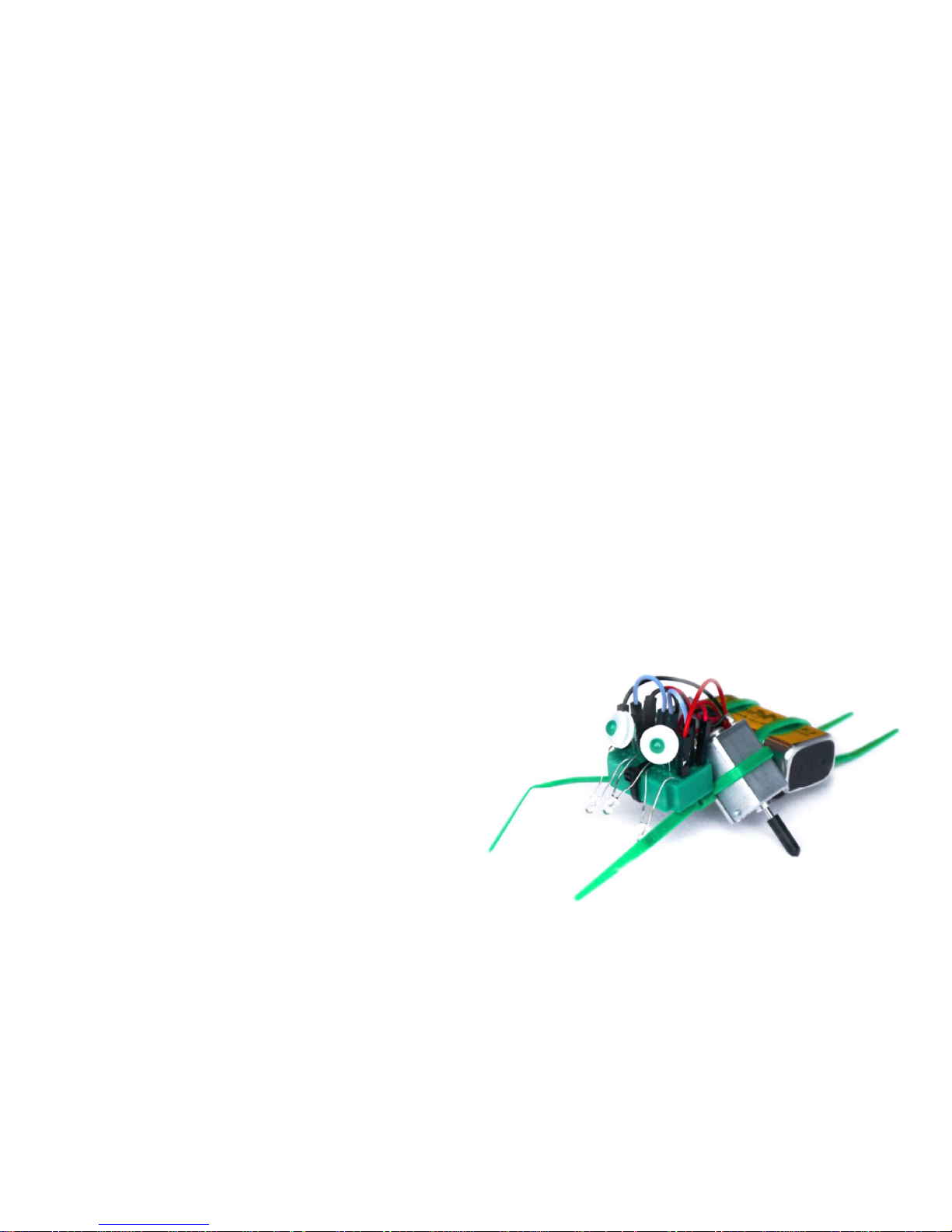
We are pleased you have chosen this
versatile robot assembly kit. varikabi offers
you an exciting and playful approach to
electronics. You will certainly have fun and
variety with varikabi for a long time.
Varikabi's "muscles" are two motors, his
"brain cells" two transistors. The simple
control circuits are placed on a small
breadboard and are therefore easily
modifiable.
With the help of a clever combination of
three brightness sensors varikabi perceives
the smallest contrasts in its environment and
reacts to them in many different ways.
Thanks to a selector switch and by aligning
and switching the sensors, you'll explore
twelve different functions and amazing
behaviors.
varikabi can do a lot:
- Overcome obstacle courses
- Follow dark or light lines
- Track or move objects
- Search, track or circle light
- Trace or circle shadows
- Circle on light or dark areas
Page 5

Content
1) Assembly
varikabi is available in the seven colors red,
blue, green, neon green, yellow, pink and
black. Regardless of the color variant, there
are seven different animal models to
choose from. Numerous illustrations show
you step by step how to assemble them.
S. 9 varikabi as a Dog
S. 17 varikabi as a Sea Lion
S. 23 varikabi as a Frog
S. 29 varikabi as a Bird
S. 35 varikabi as a Giraffe
S. 43 varikabi as a Mouse
S. 51 varikabi as a Beetle
S. 60 varikabi - Fischertechnik
2) Functions
The experimentation manual explains the
twelve functions of varikabi. It will show
you how to build the appropriate circuits,
connect the motors and set the three
sensors. Finally, find a fault diagnosis in
case something does not work as expected.
3) Operating Principle
You will learn how the different control
circuits and components of the kit work. You
will learn varikabis behaviors and
understand how they are caused.
This part of the manual is still under
construction and will be updated
continuously.
Page 6
1) Assembly
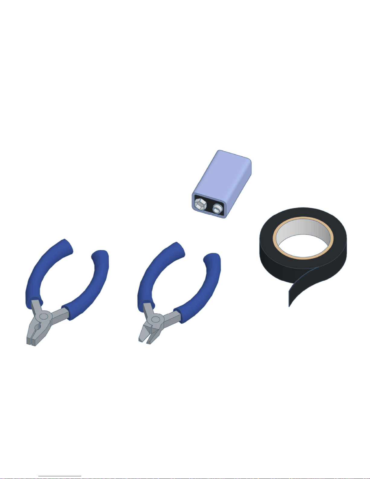
What you need
• 9 V block battery or 9 V battery
• pliers and side cutters
• black duct tape (for varikabi FT)
• about one hour time
Page 7
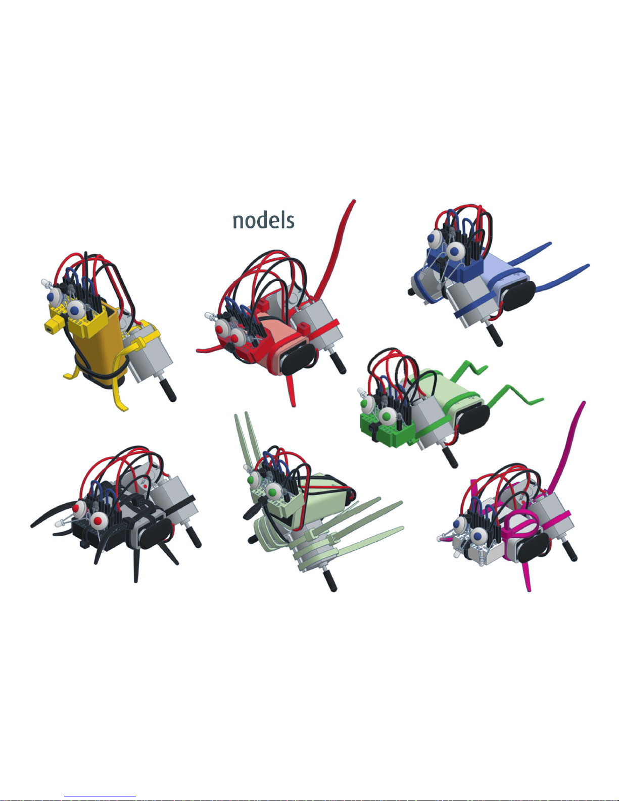
The seven varikabi models
Page 8
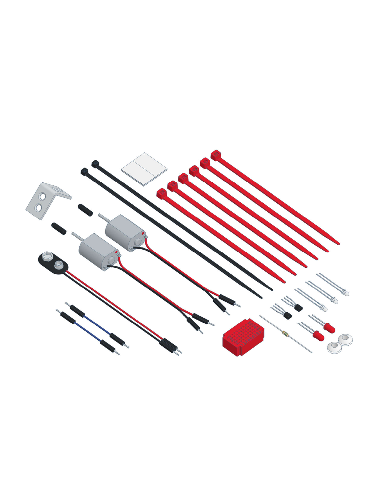
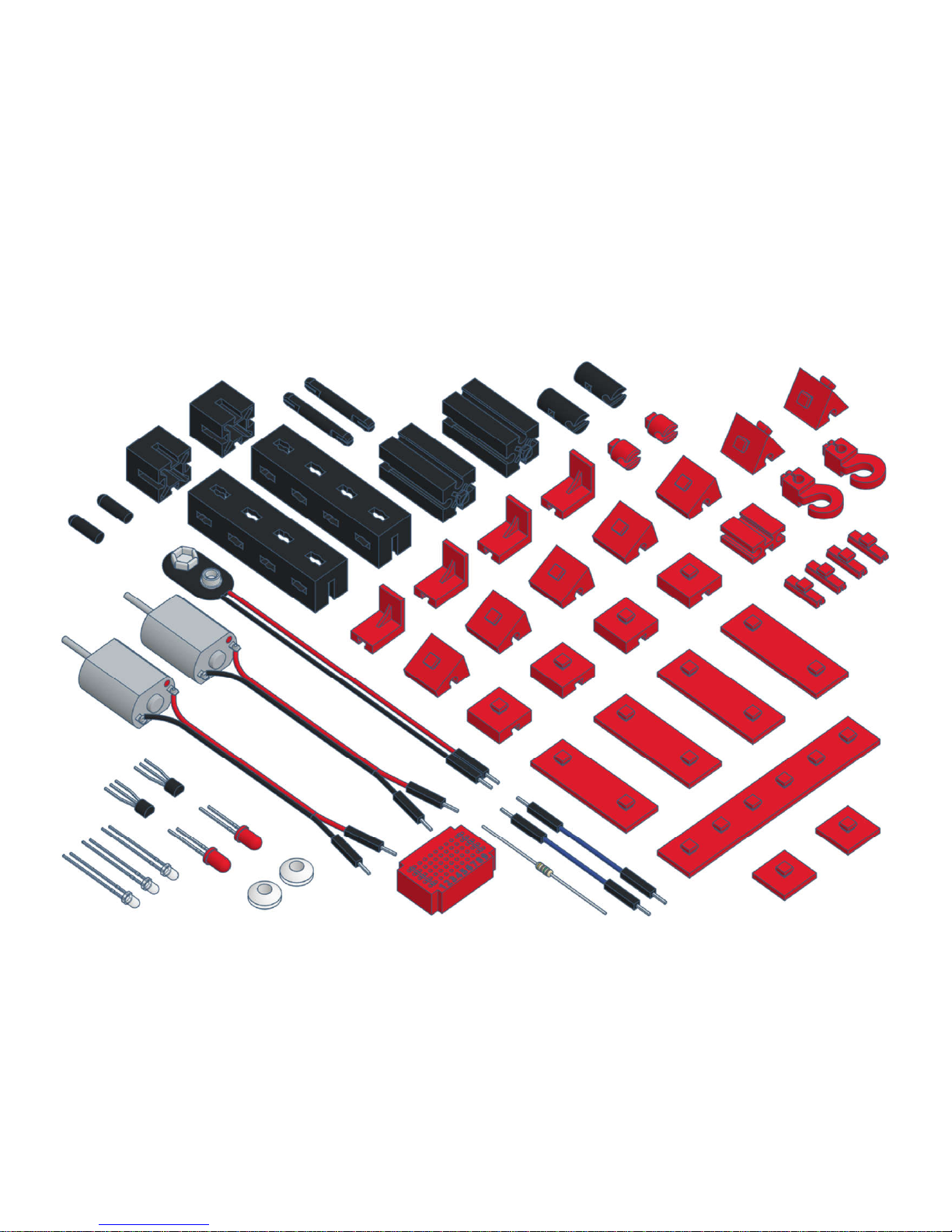
The components
Page 9
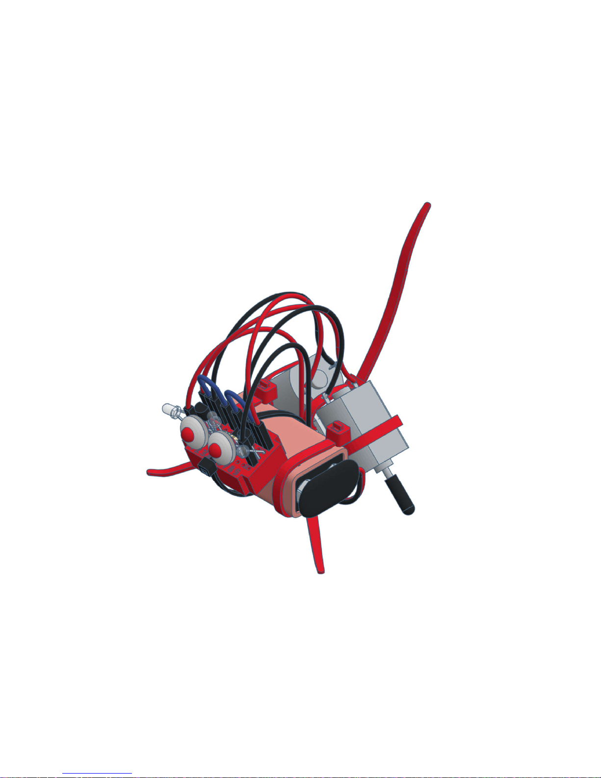
varikabi as a Dog
Page 10
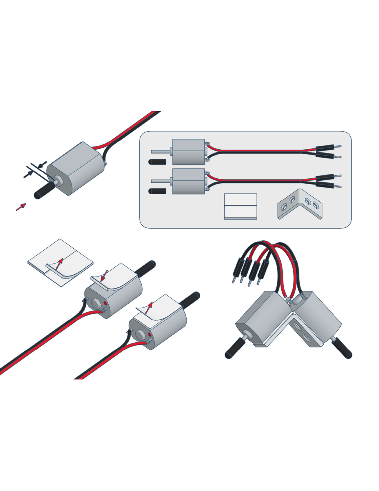
1)
Page 11
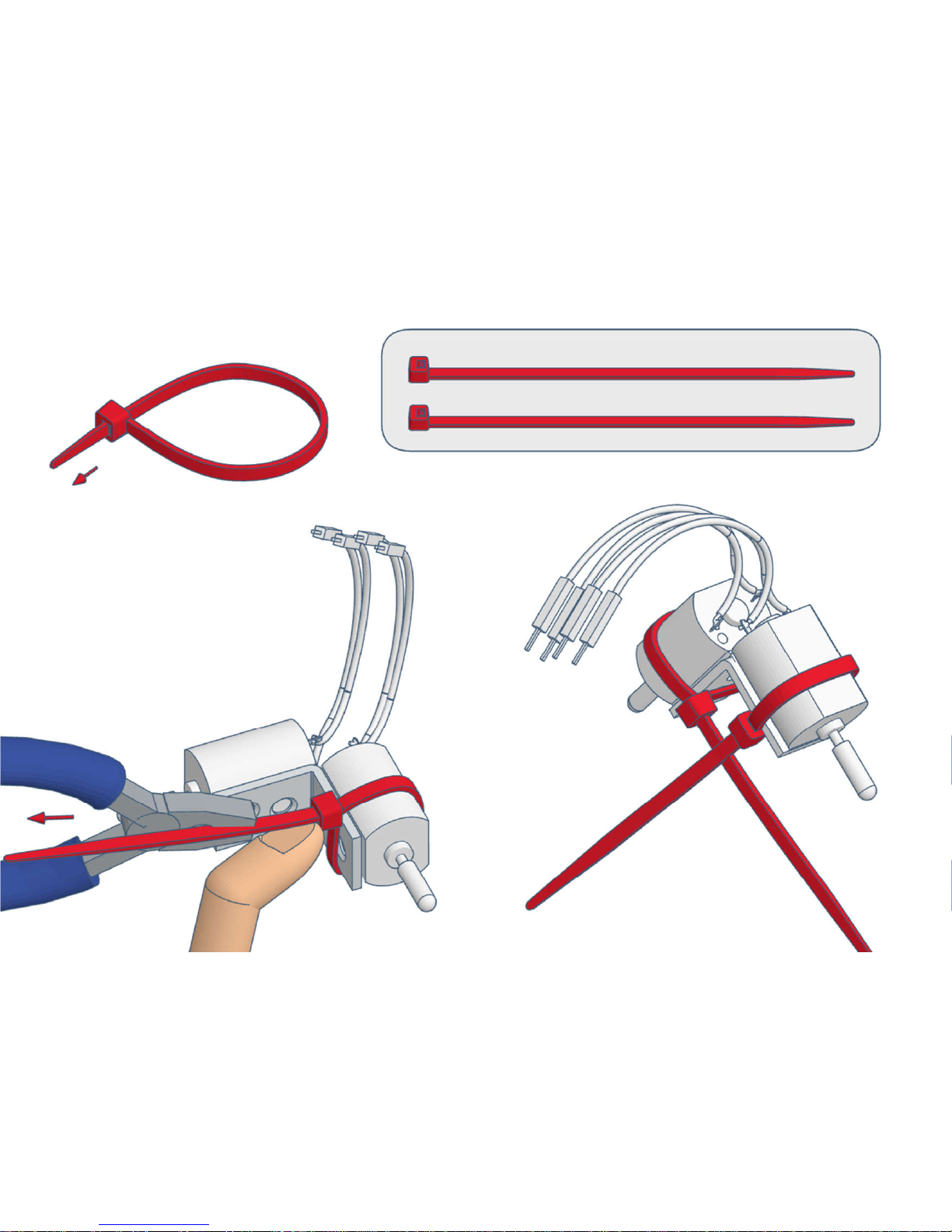
2)
Page 12
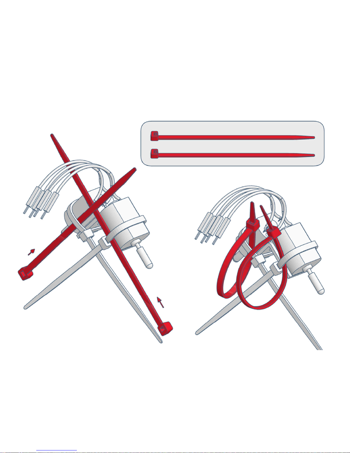
3)
Page 13
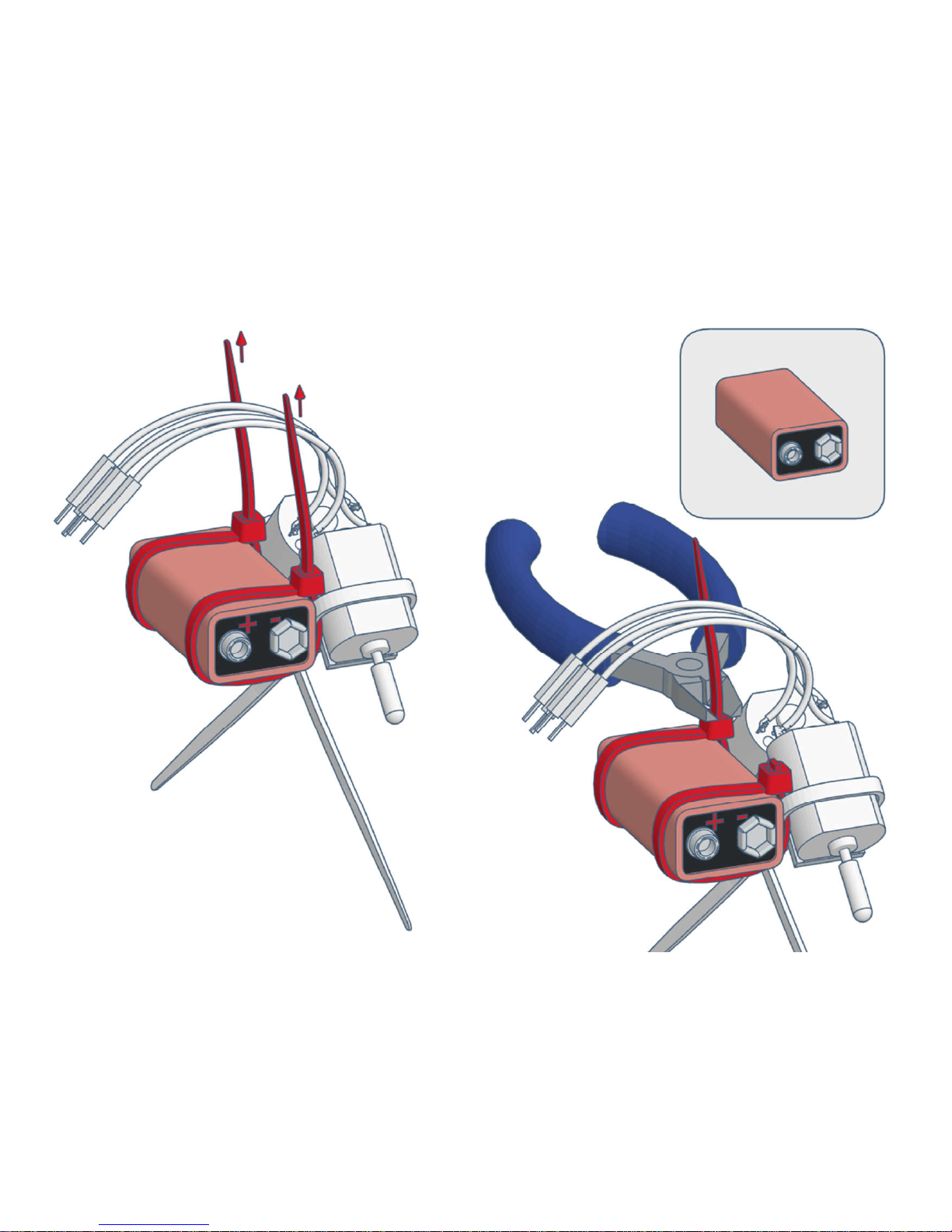
4)
Page 14
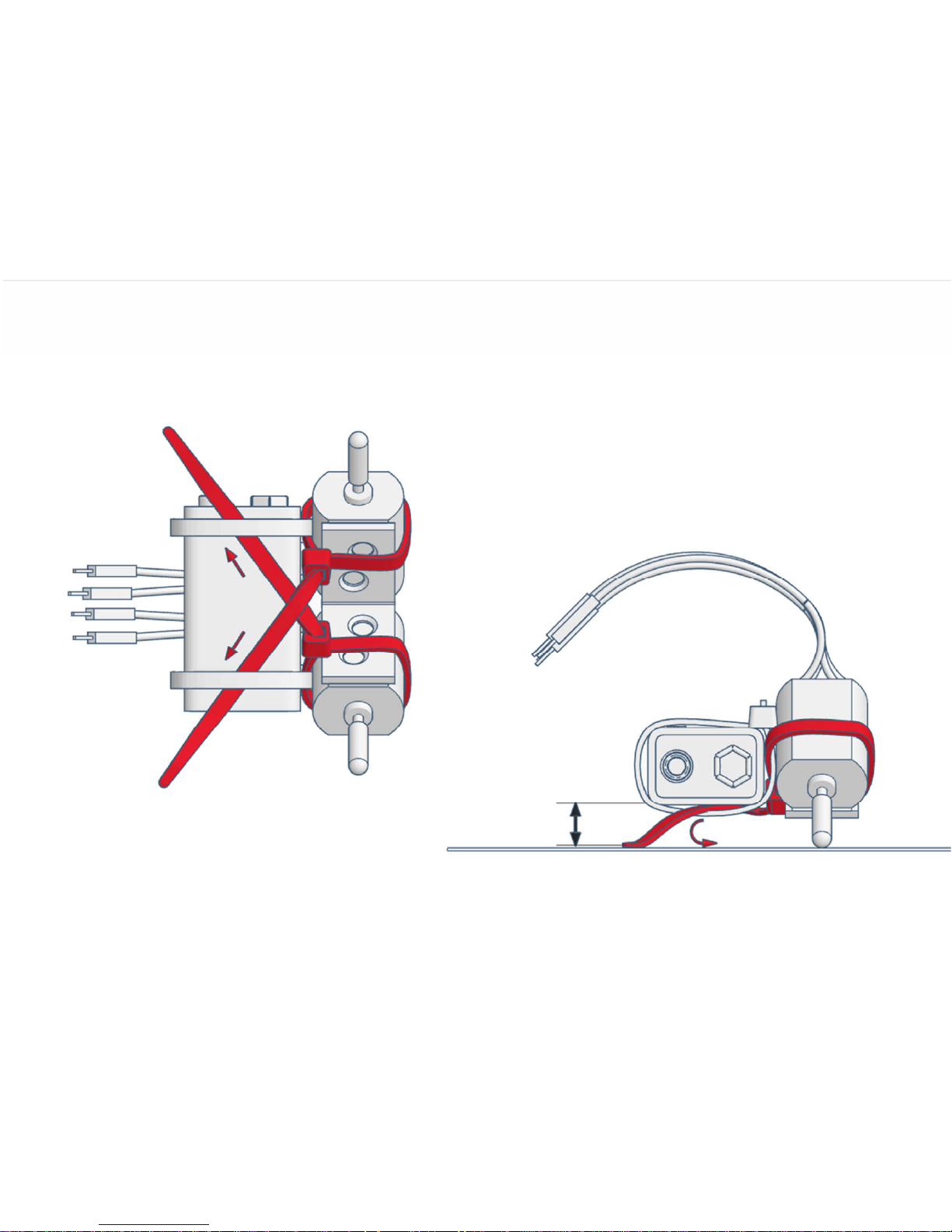
5)
Page 15
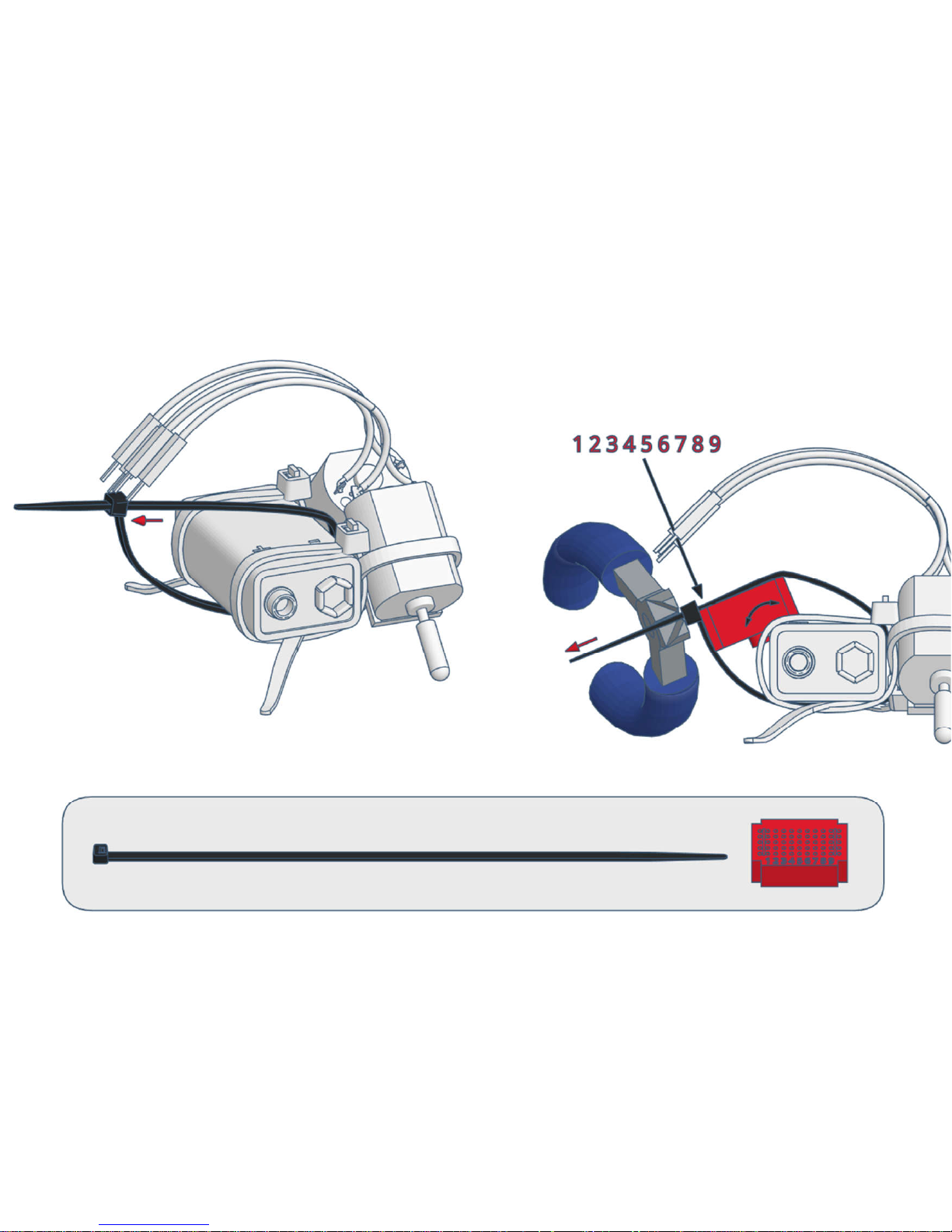
6)
Page 16
7)
Page 17
varikabi as a Sea Lion
Page 18
1)
Page 19
2)
Page 20
3)
Page 21
4)
Page 22
5)
Page 23
varikabi as a Frog
Page 24
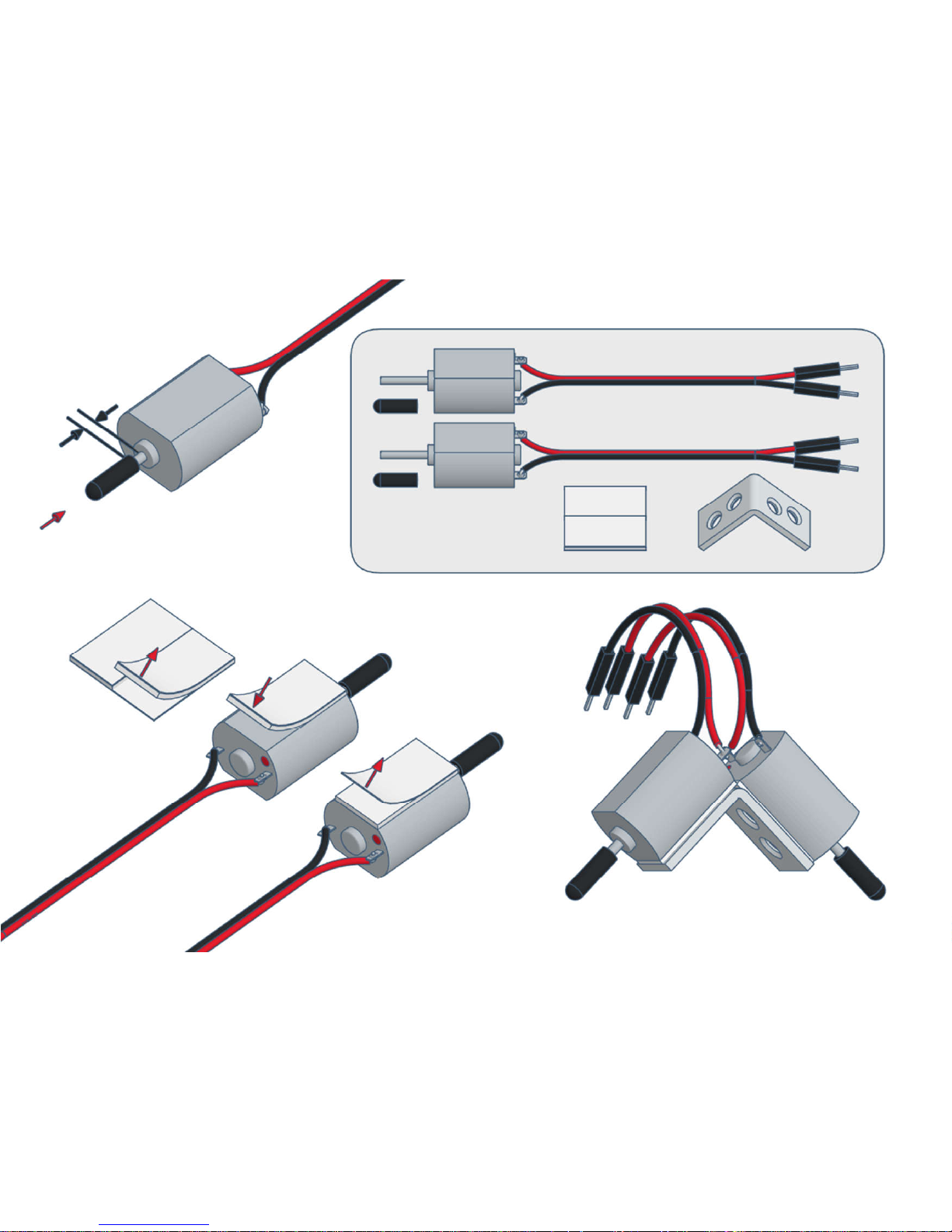
1)
Page 25
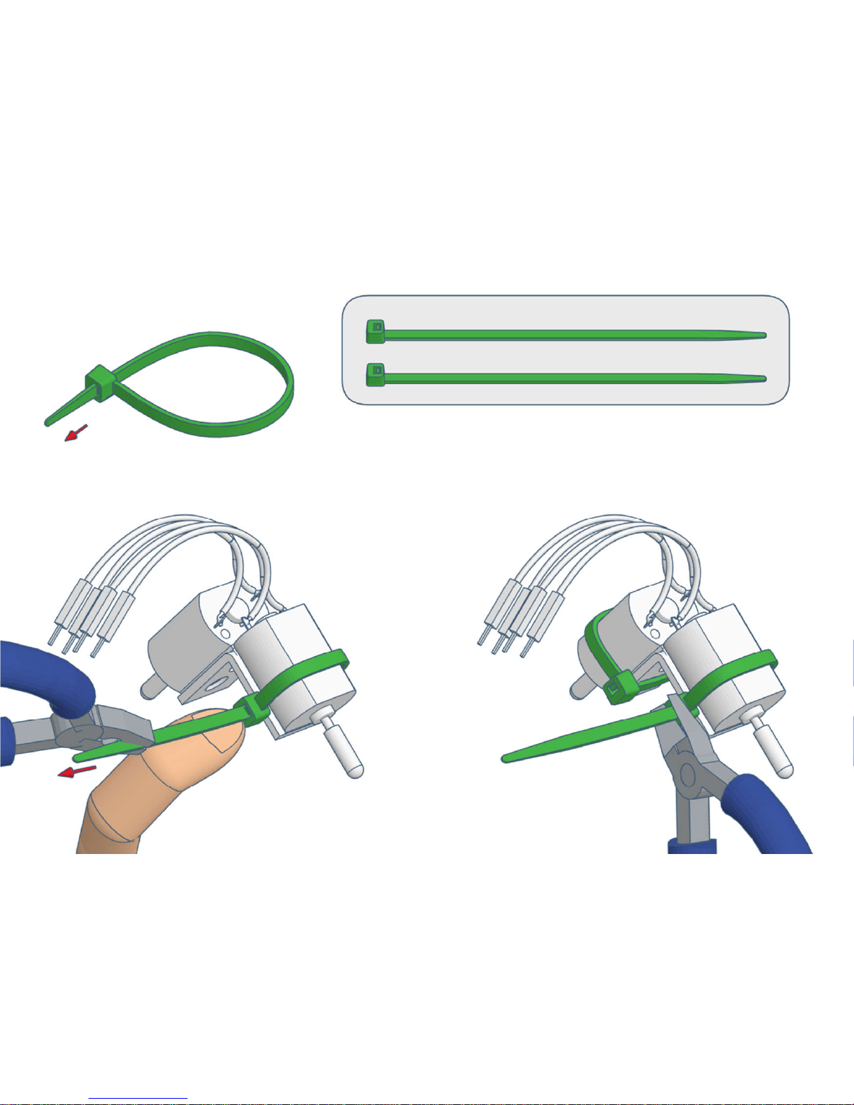
2)
Page 26
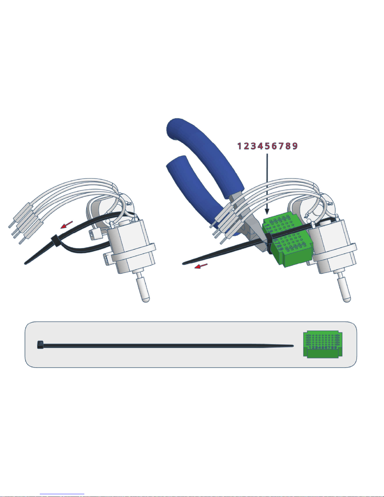
3)
Page 27
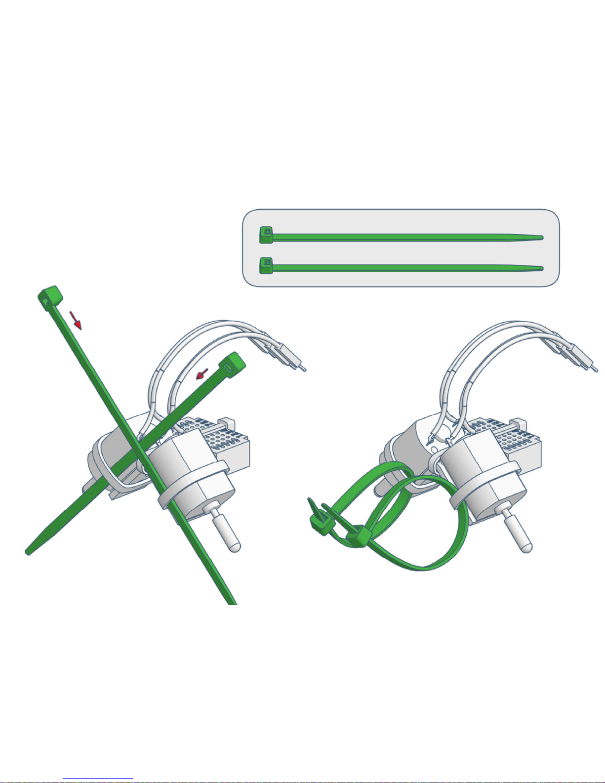
4)
Page 28
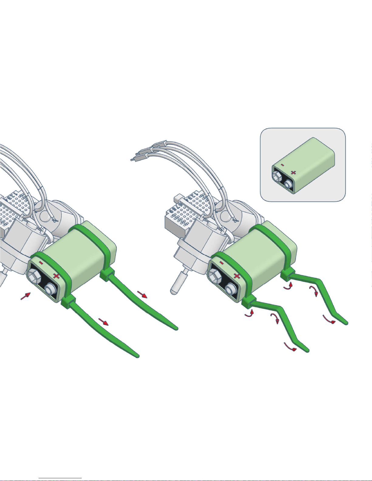
5)
Page 29
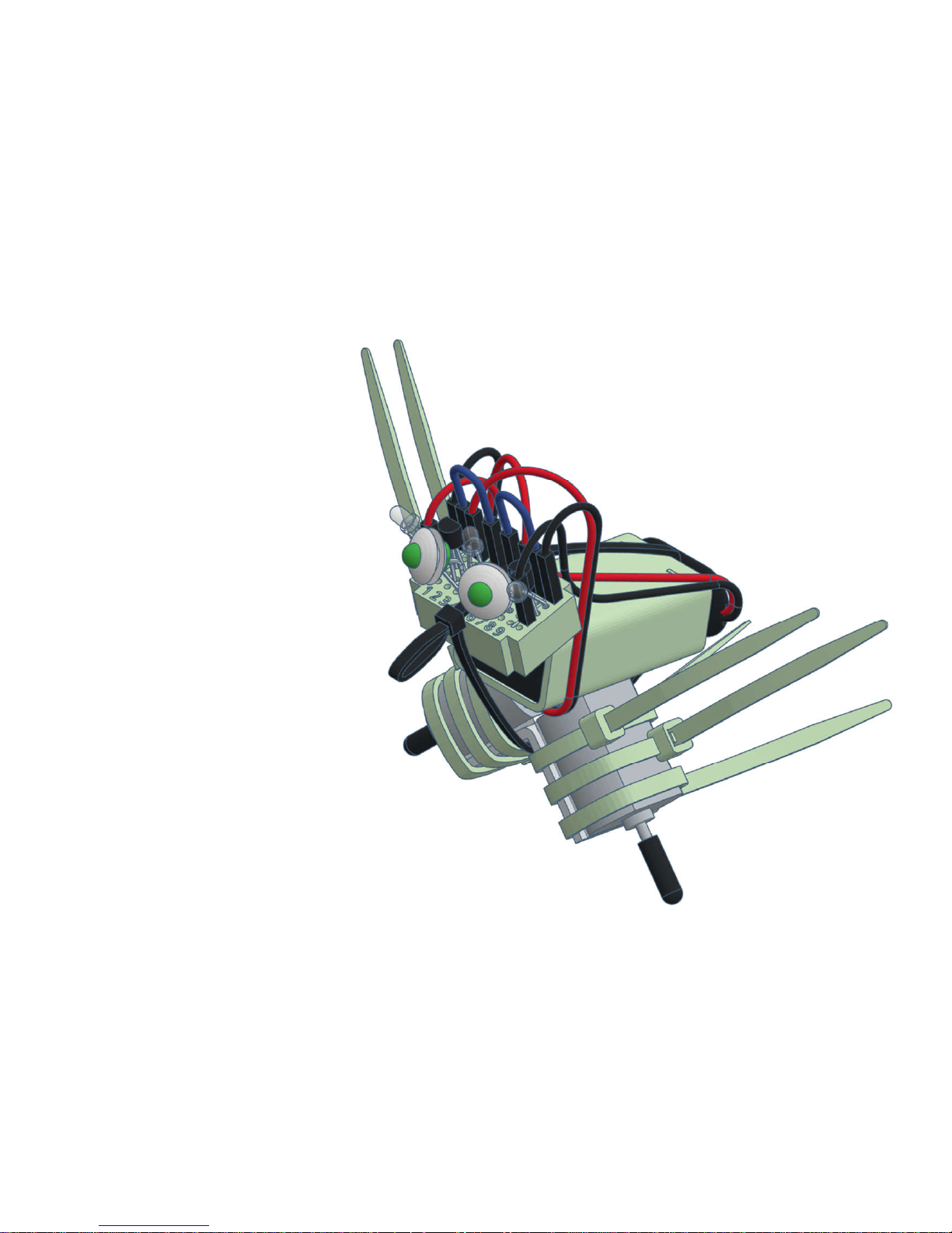
varikabi as a Bird
Page 30
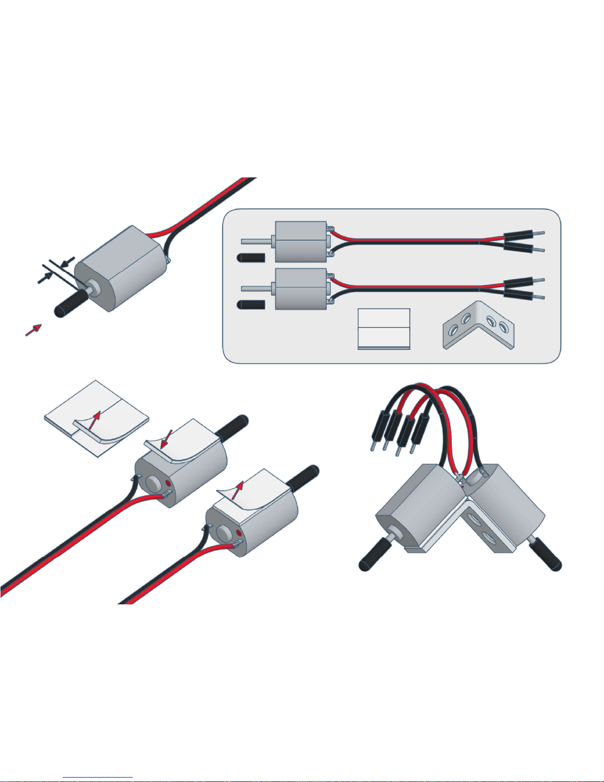
1)
Page 31
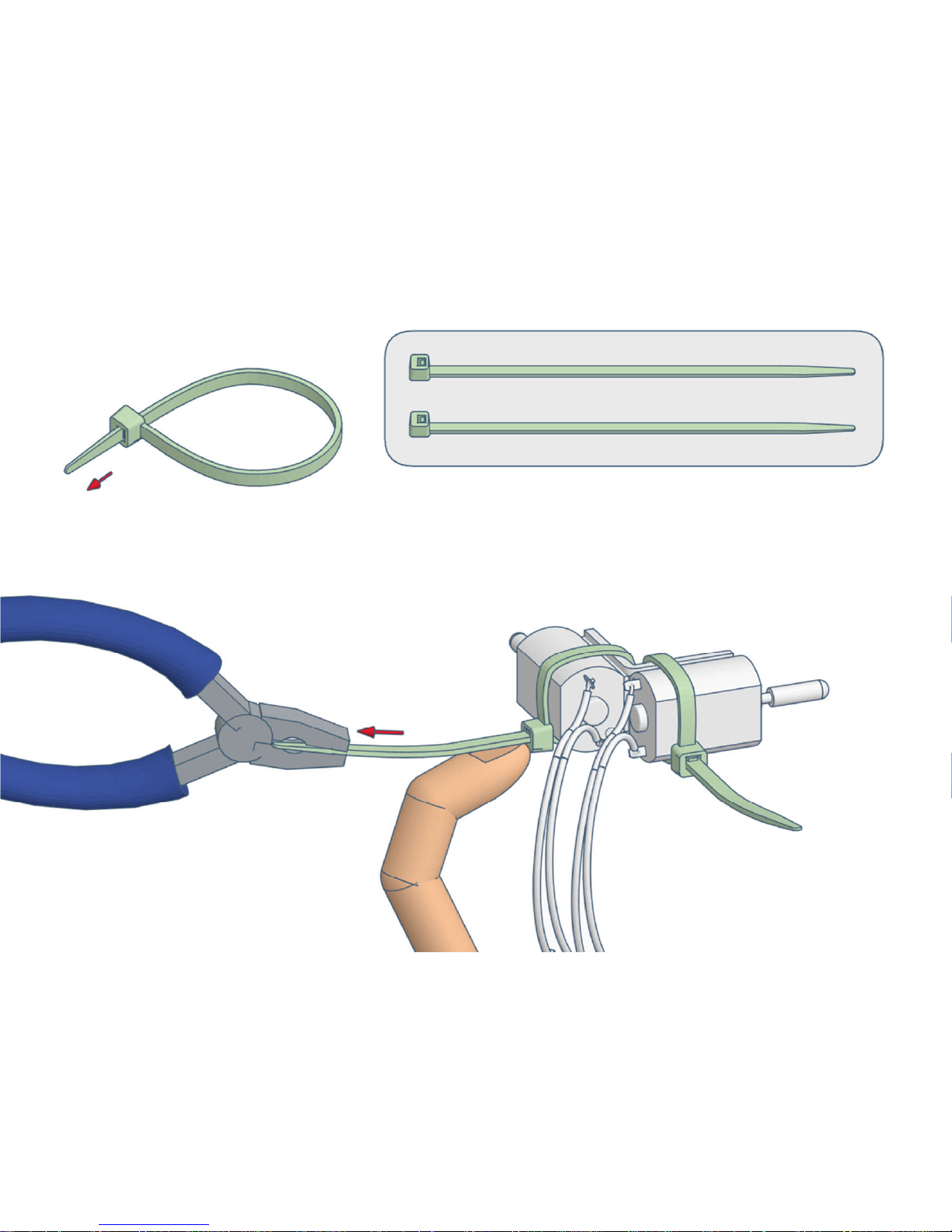
2)
Page 32
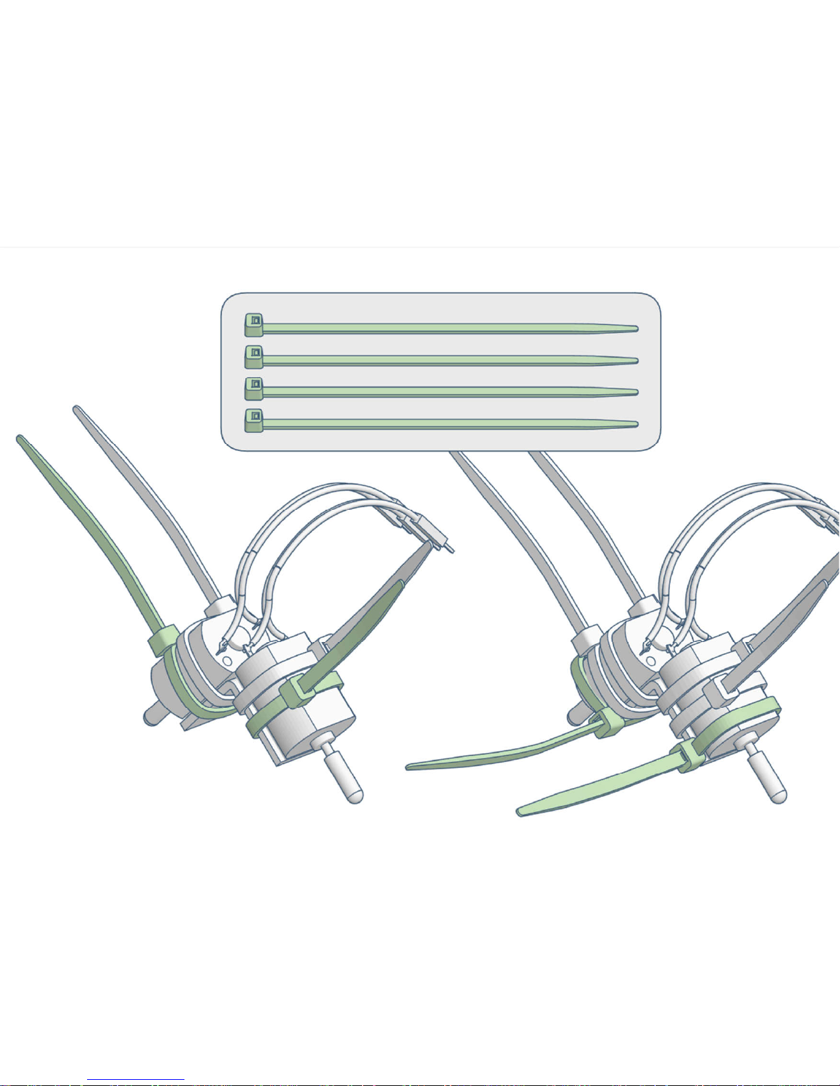
3)
Page 33
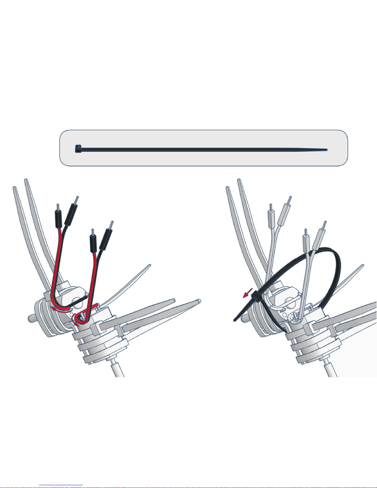
4)
Page 34
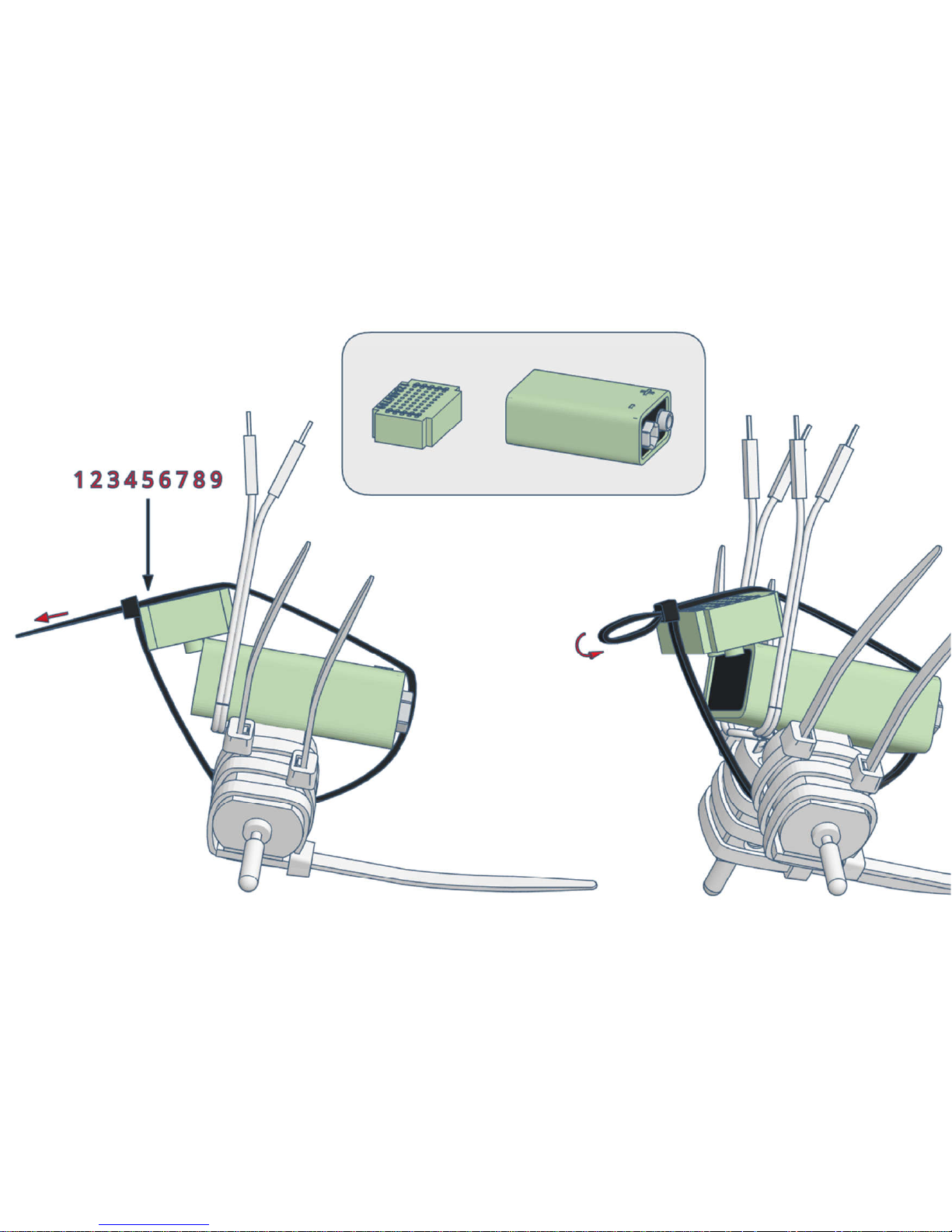
5)
Page 35
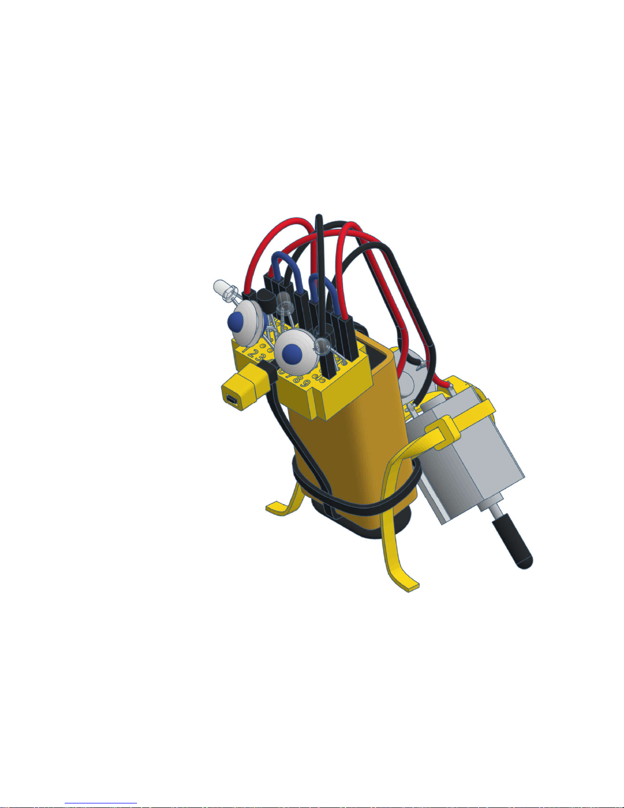
varikabi as a Giraffe
Page 36
1)
Page 37
2)
Page 38
3)
Page 39
4)
Page 40
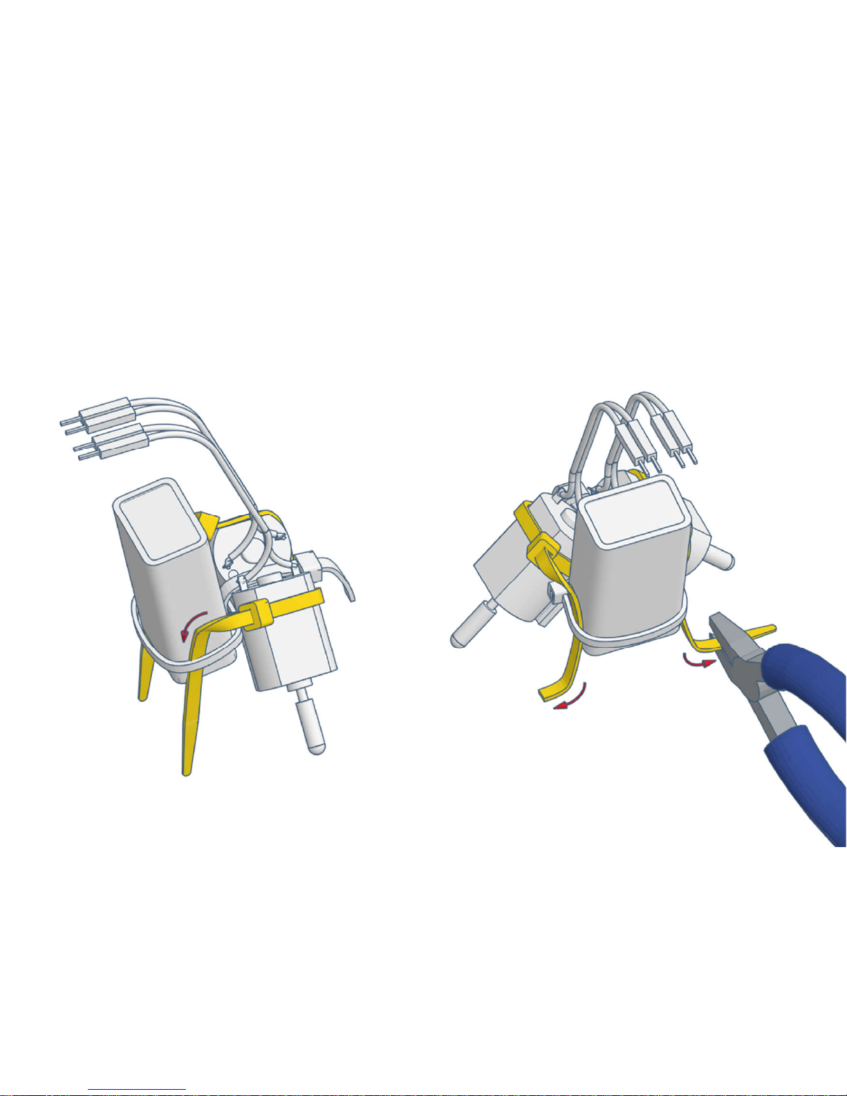
5)
Page 41
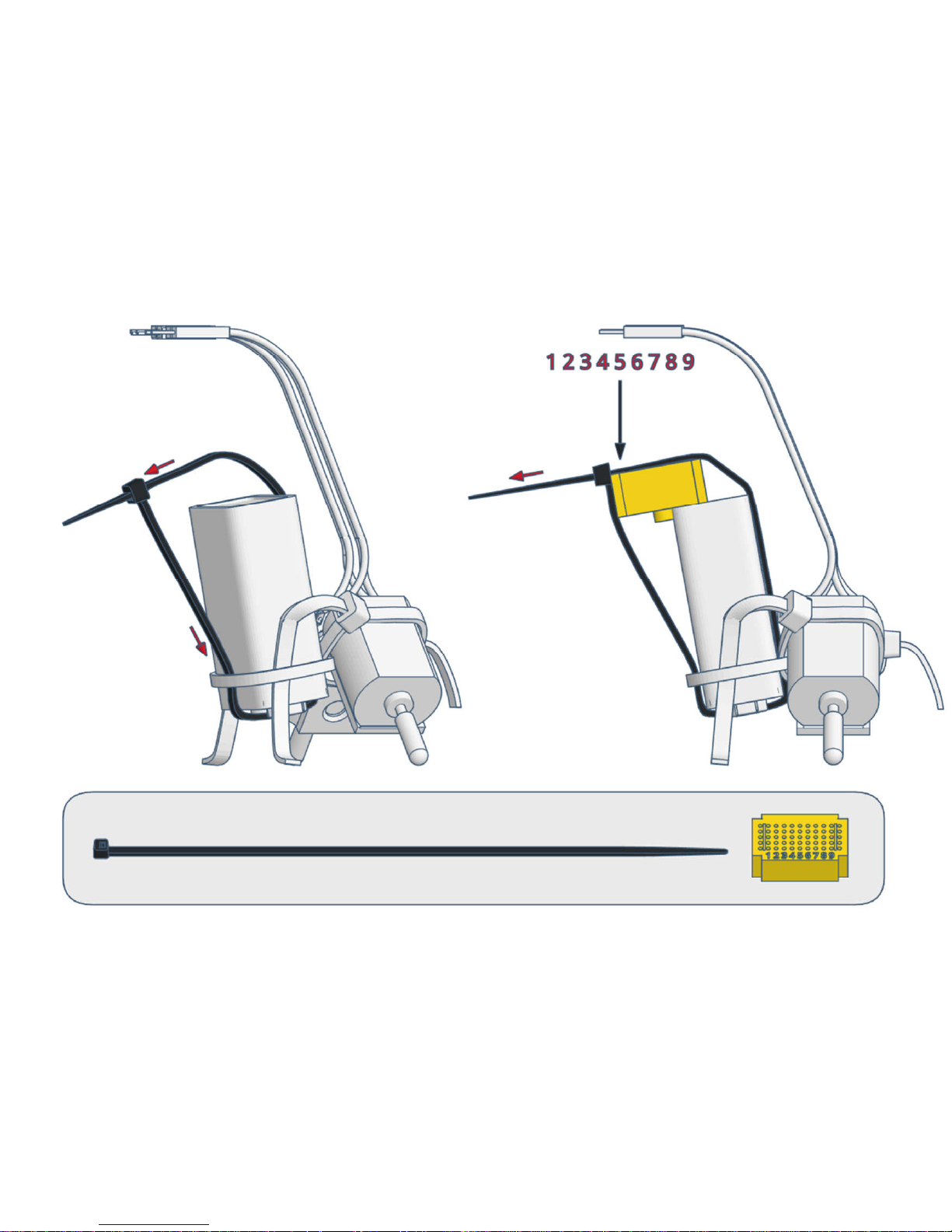
6)
Page 42
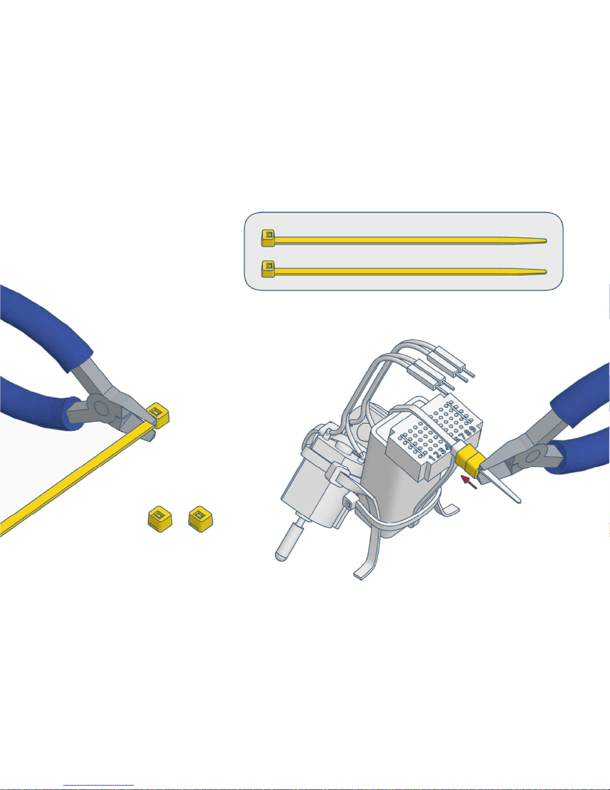
7)
Page 43
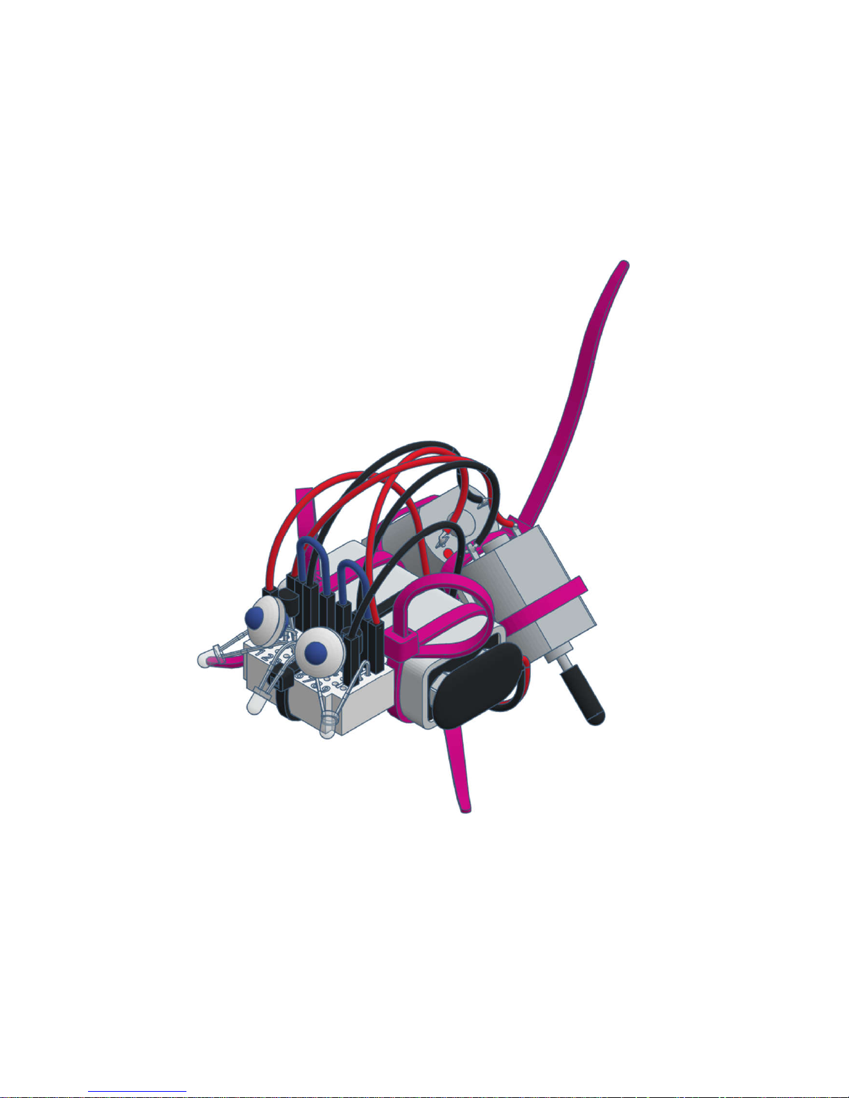
varikabi as a Mouse
Page 44
1)
Page 45
2)
Page 46
3)
Page 47
4)
Page 48
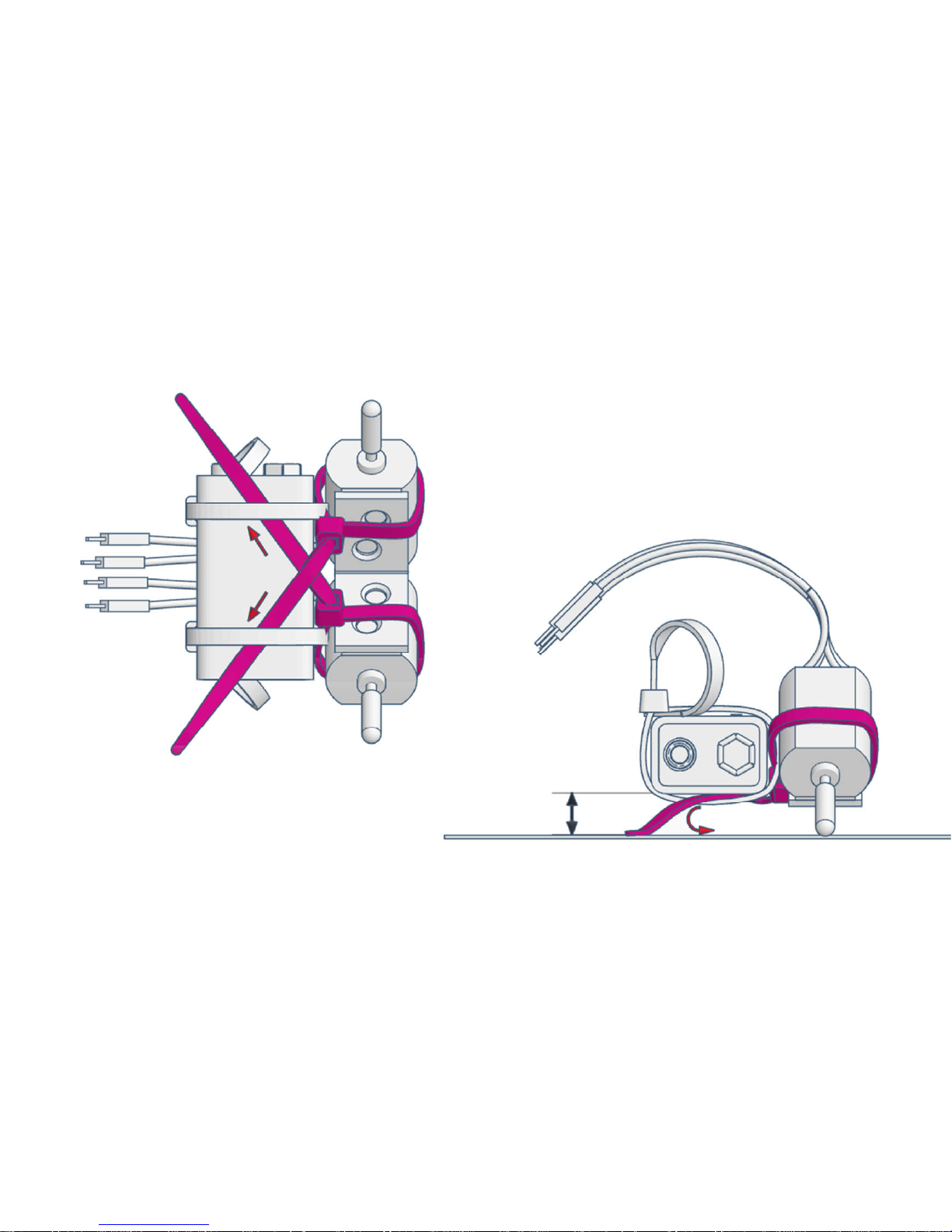
5)
Page 49
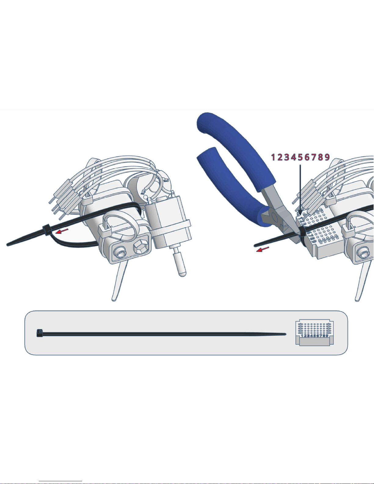
6)
Page 50
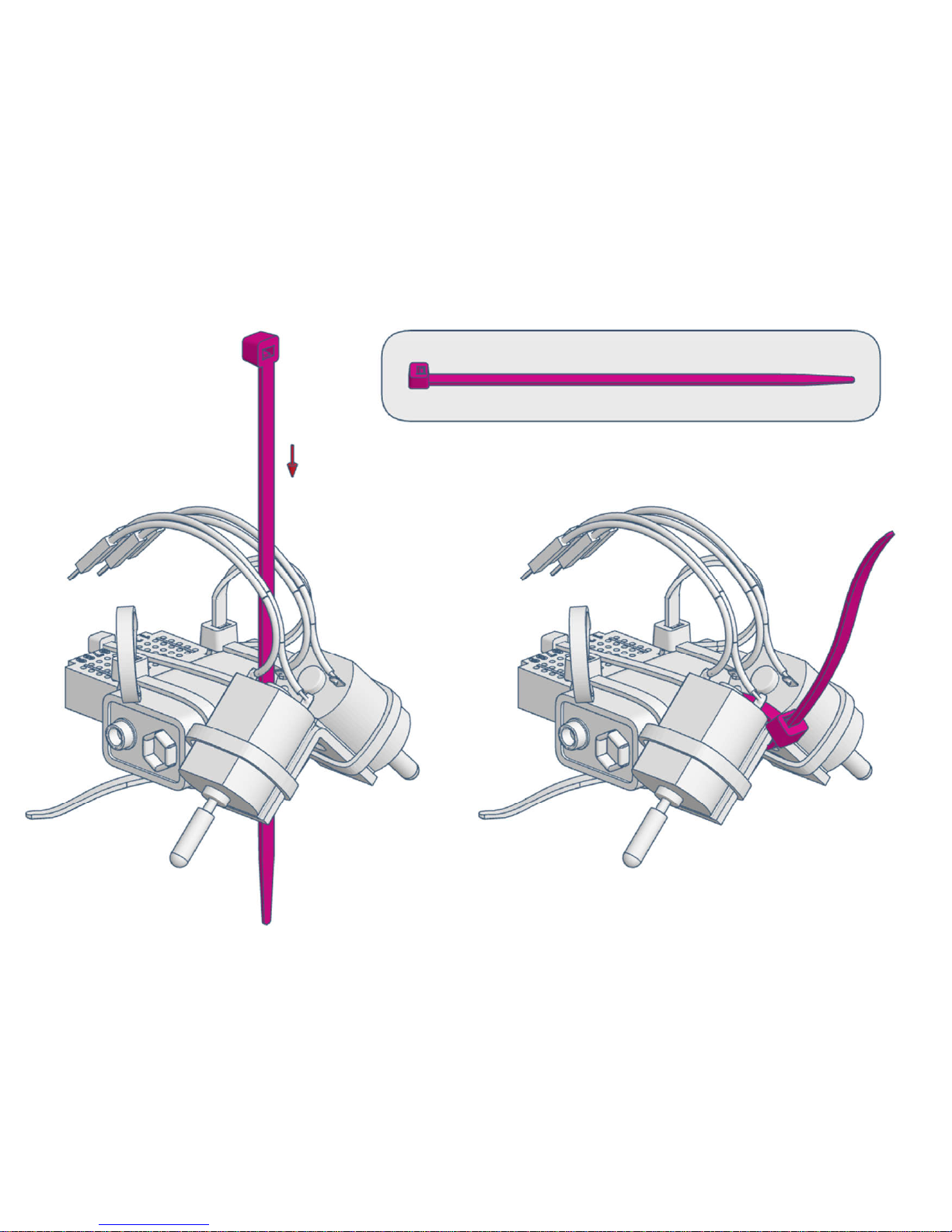
7)
Page 51
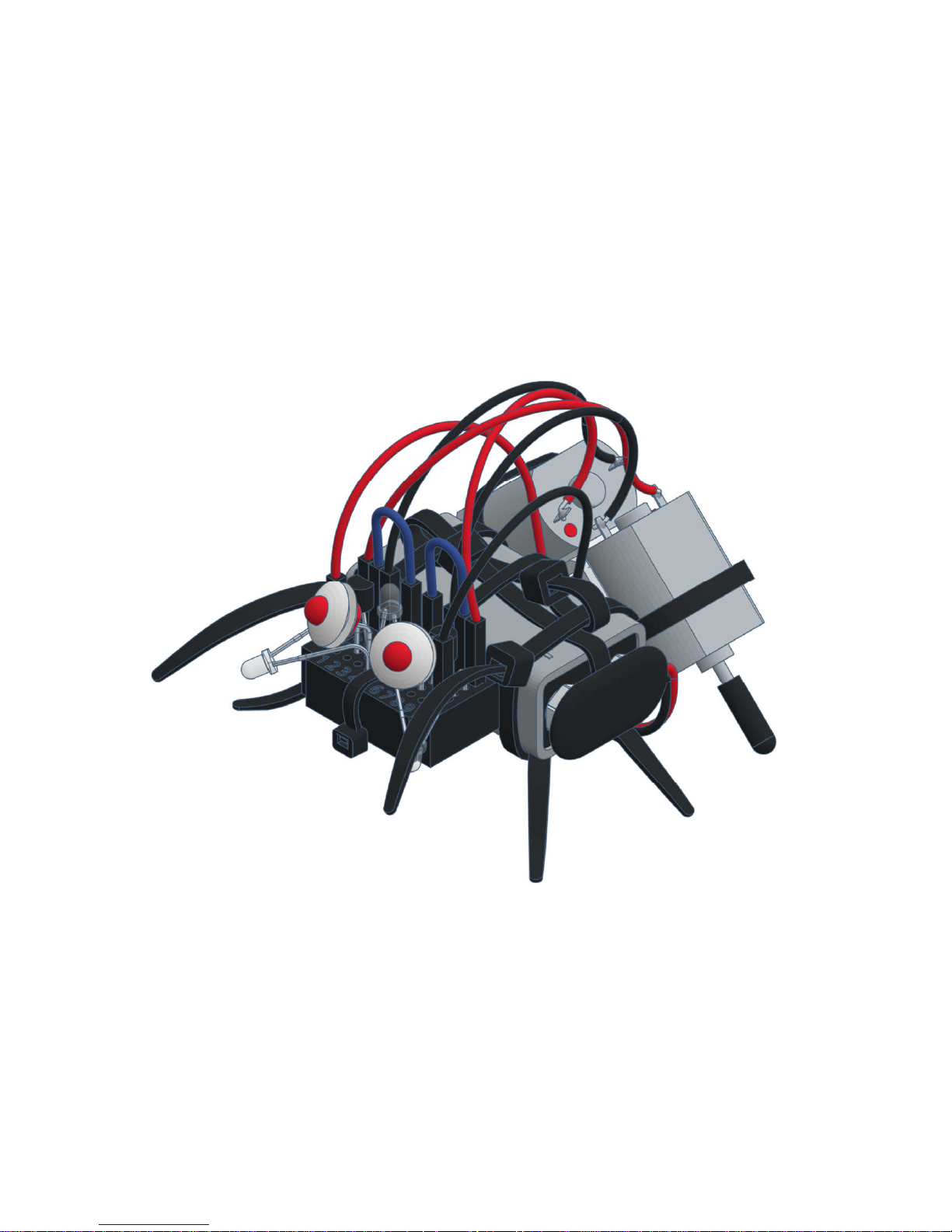
varikabi as a Beetle
Page 52
1)
Page 53
2)
Page 54
3)
Page 55
4)
Page 56

5)
Page 57
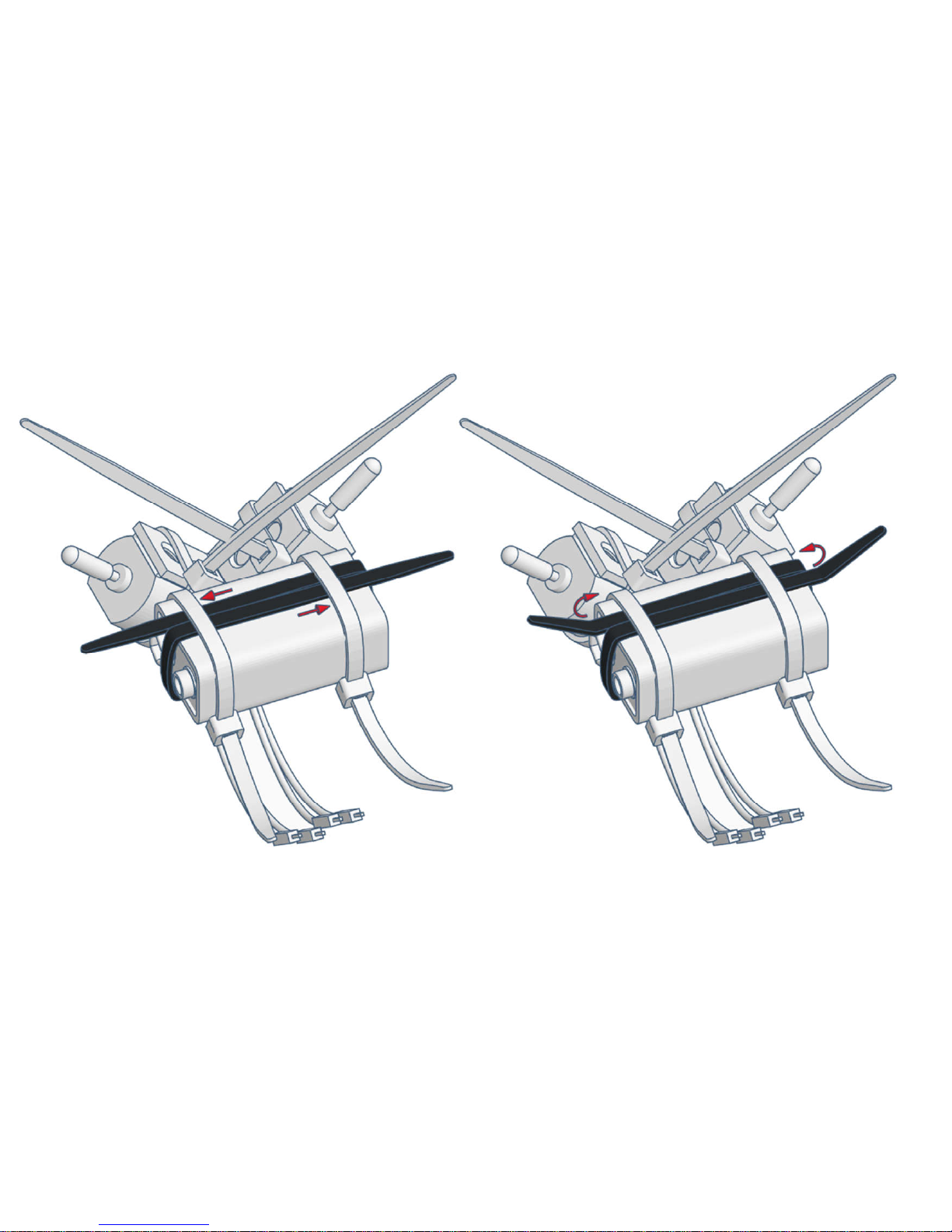
6)
Page 58
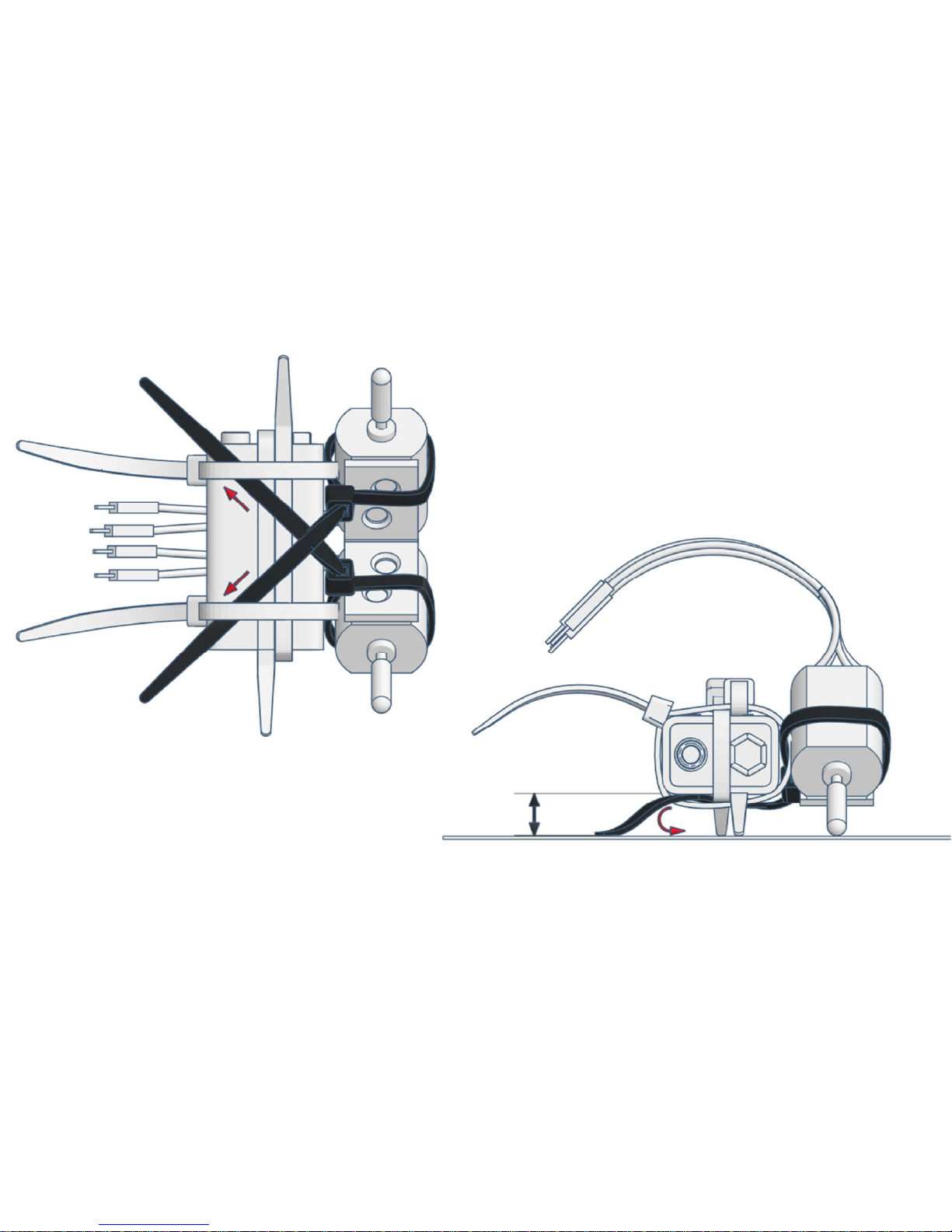
7)
Page 59
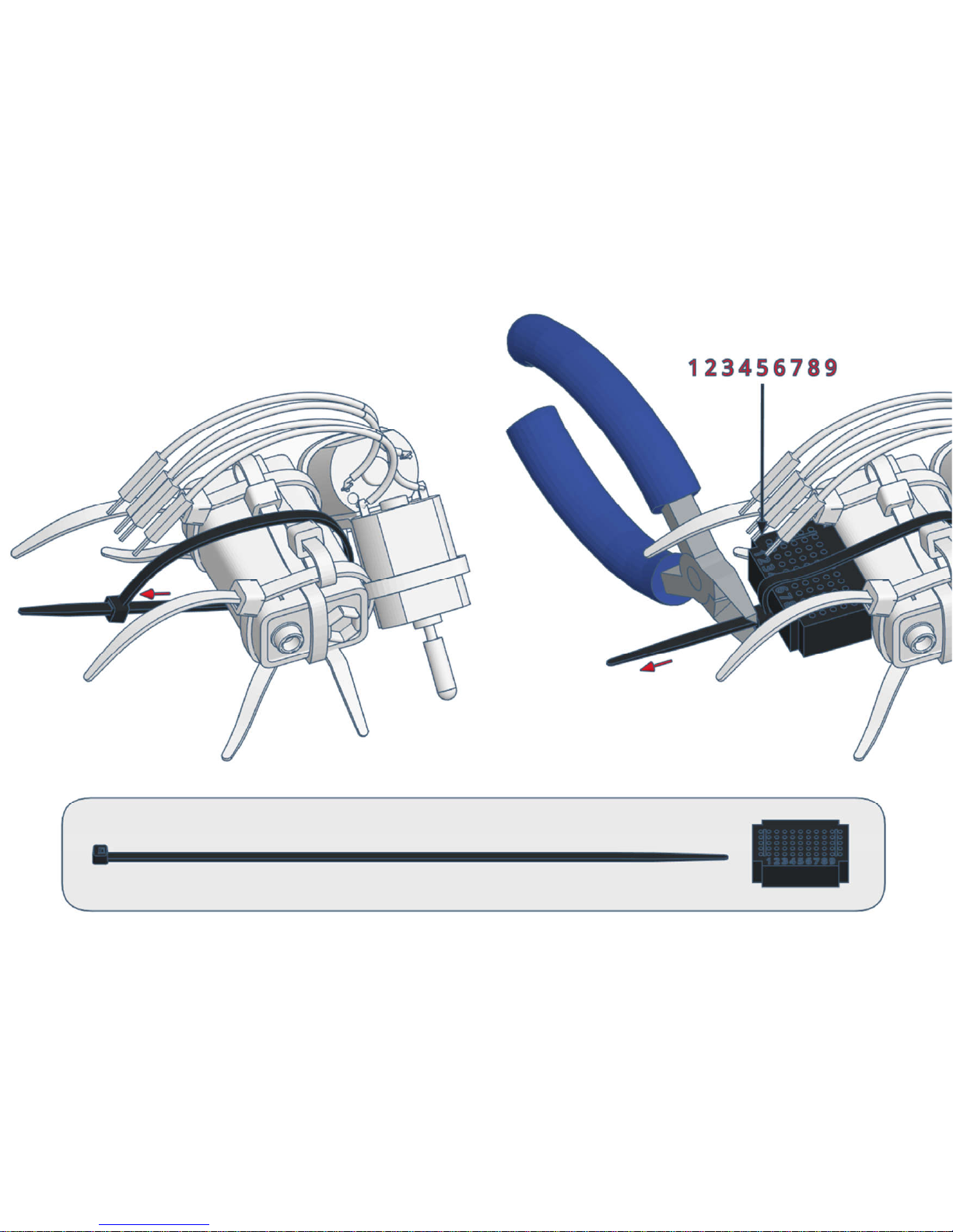
8)
Page 60
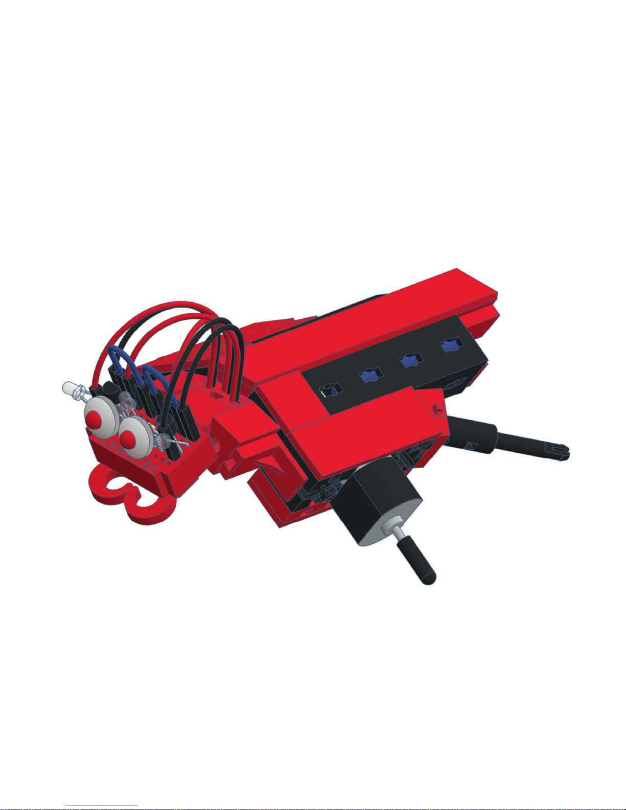
varikabi - Fischertechnik
Page 61
The components
Page 62
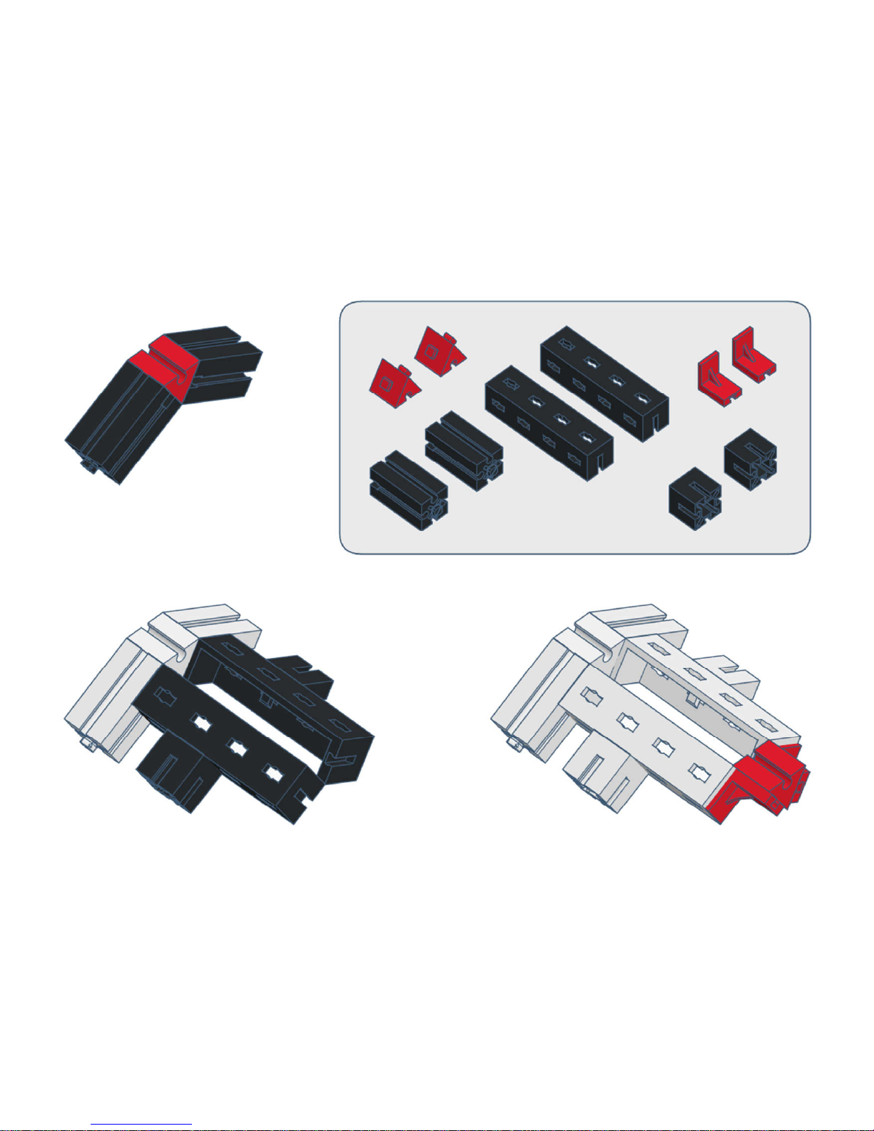
1)
Page 63
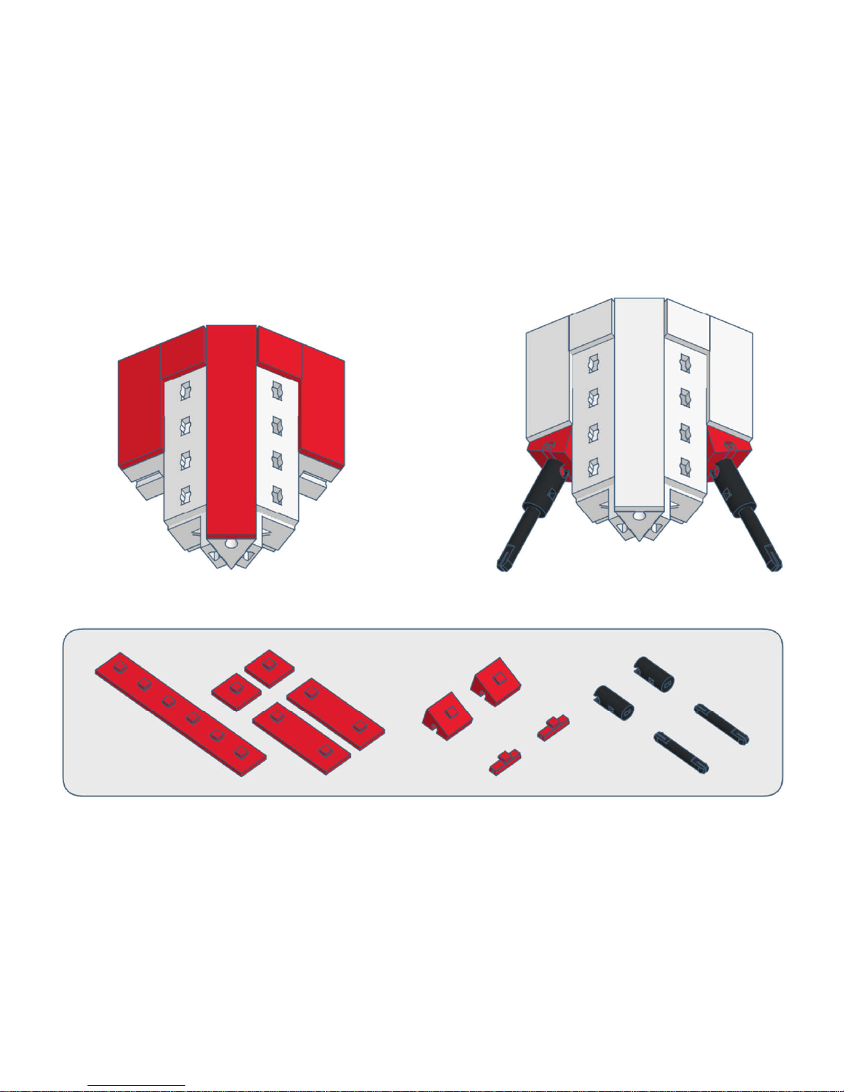
2)
Page 64
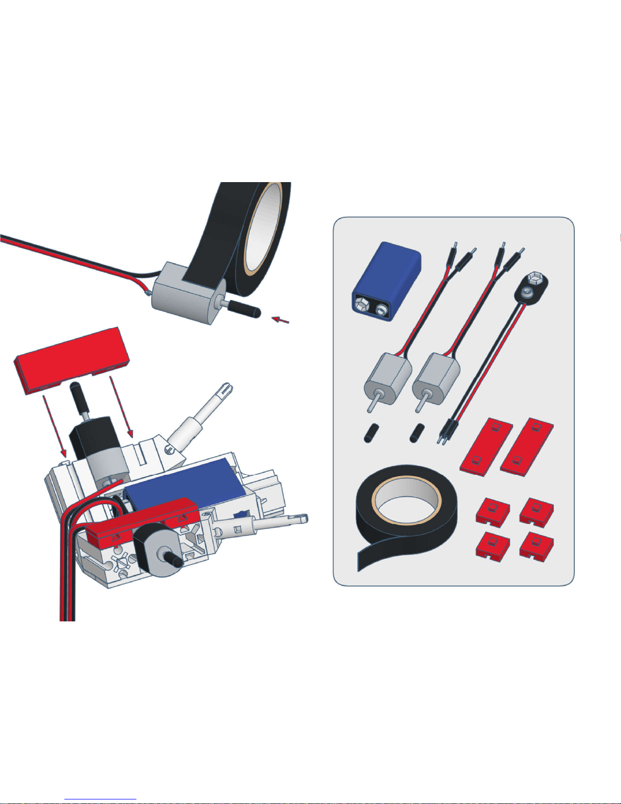
3)
Page 65
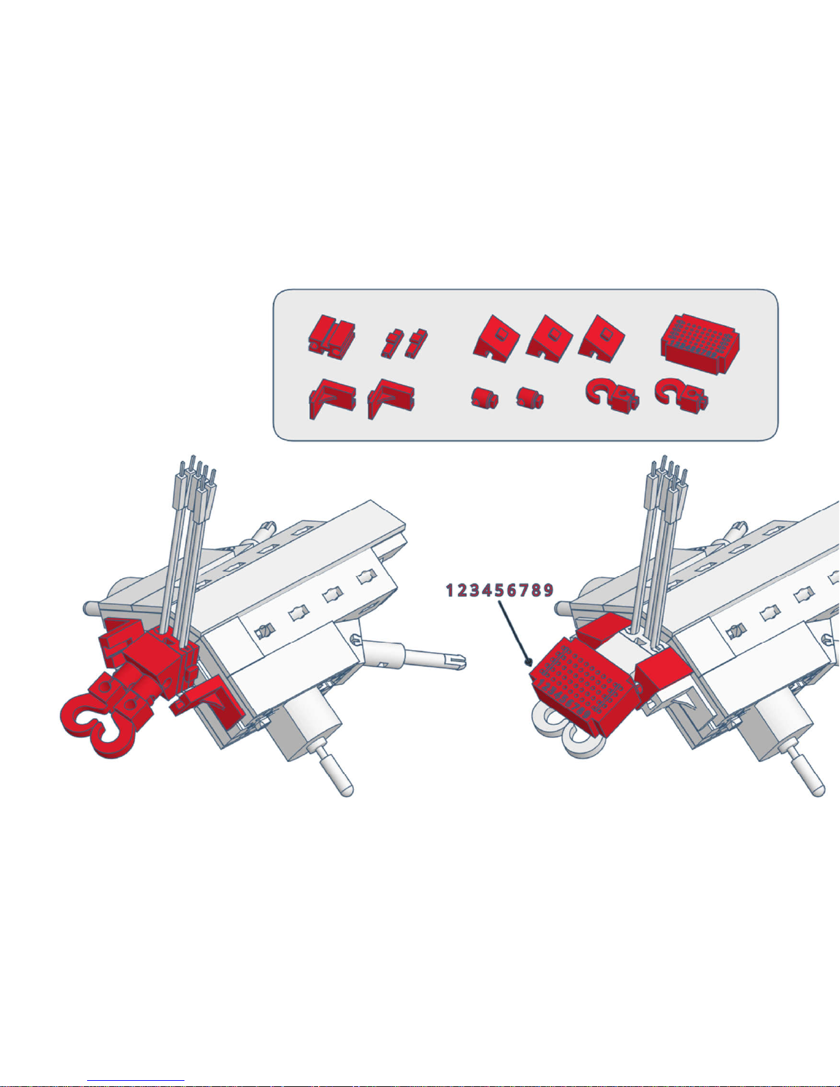
4)
Page 66
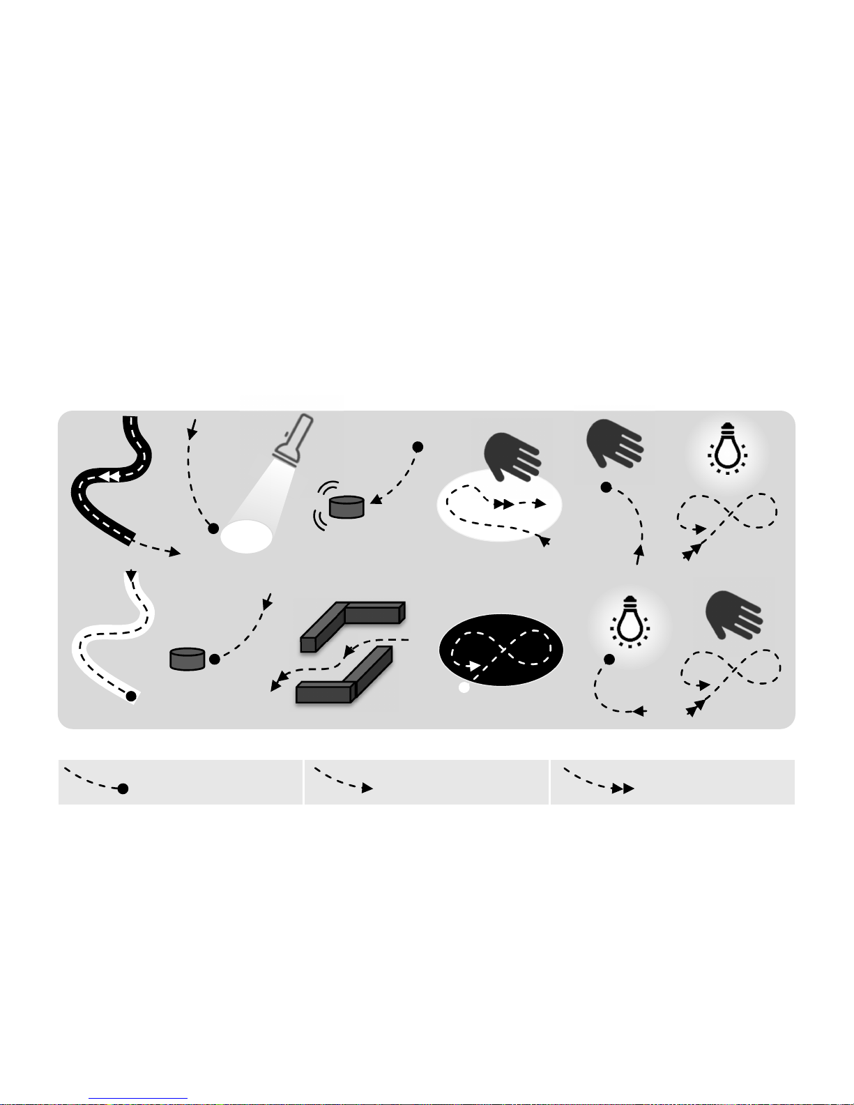
2) Circuits and Functions
The different circuit variants allow varikabi twelve functions. The circuits and features of the
functions are described below in detail.
varikabi stands still
varikabi drives slowly varikabi drives fast
Page 67

Unlike many other robots, varikabi does not
need to emit infrared light to detect lines or
objects in front of it. This simplifies the
circuit and reduces power consumption.
Since varikabi reacts on brightness
differences in the environment, it is
essential to use a suitable light source.
To avoid that varikabi's sensors are not
blinded by the light source, attention must
also be paid to a suitable position in relation
to lamps or windows.
If varikabi is supposed to follow or avoid a
structure on the ground, make sure that the
ground does not reflect light.
Notes on Lighting
Note:
The light of LED lamps or fluorescent
lamps has a low red component and
is not well perceptible for varikabi's
sensors.
When using these light sources, a
sufficiently strong illumination must
therefore be provided.
Note:
Most functions can be performed best
under a sufficiently distant lamp or
under a window on the floor.
In the case of lateral light incidence
varikabi would follow this light or its
own shadow instead of driving to the
desired target.
Page 68
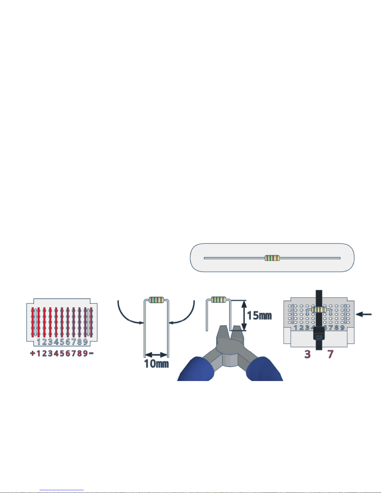
Breadboard Resistor
With a breadboard simple electronic circuits
can be set up and changed very quickly.
Our small breadboard has eleven rows of
five pins each connected internally. The
outer two rows are used for the power
supply (+/-). The rest are labeled with the
numbers 1 to 9.
The fifth row in the middle is concealed at
varikabi with the black cable tie and is not
needed.
The resistor limits the current of the two
LEDs. The colored rings indicate the value of
the ohmic resistance, which in our case is
150 Ω (ohms).
Bend the connecting wires of the resistor at
a distance of 10 mm and shorten them to a
length of approx. 15 mm. Then put the
resistor in the center of the breadboard.
Page 69
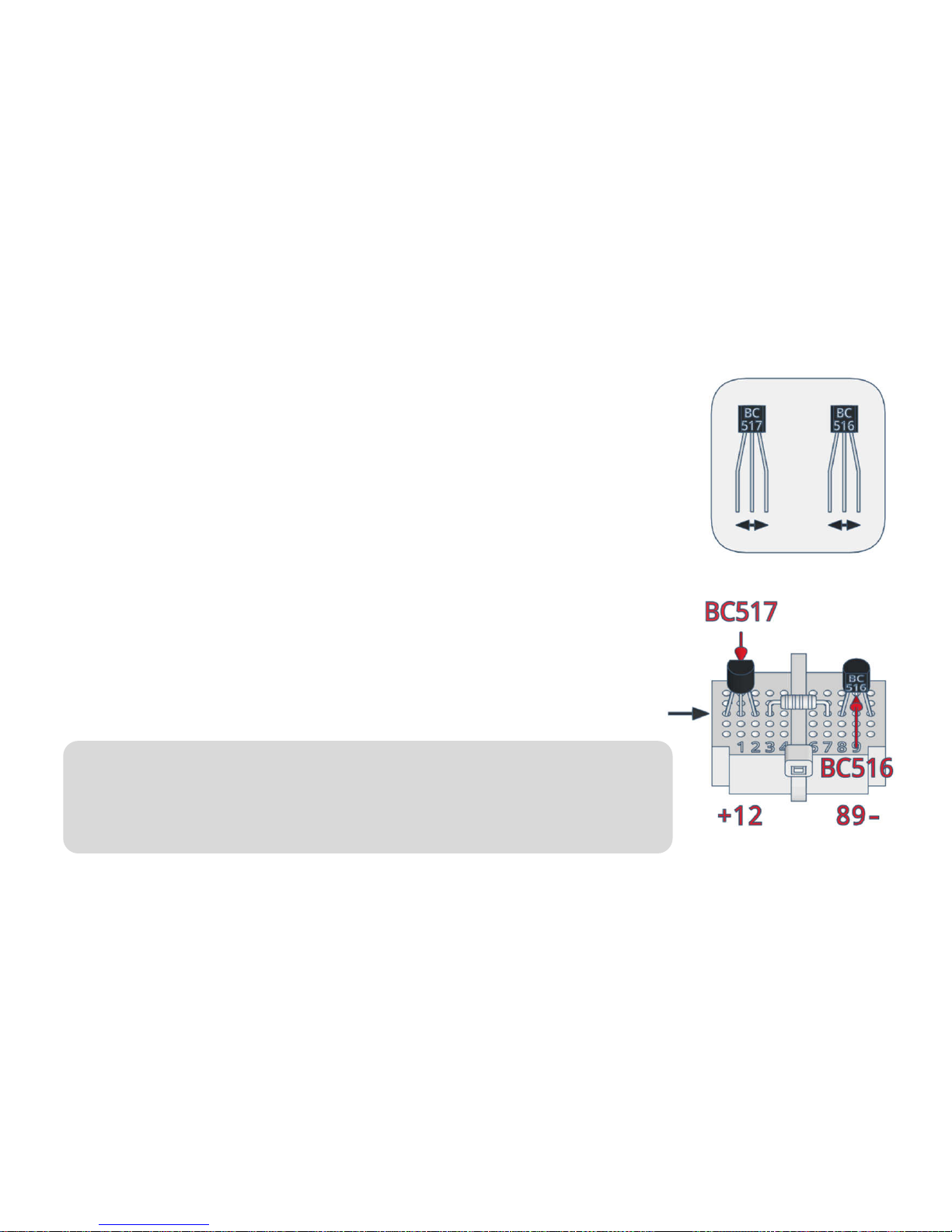
Transistors
Since varikabi's drive motors require a much higher current than the
sensors can supply, amplifiers are needed. A transistor is a simple
three-terminal electronic amplifier.
To make sure that the gain is sufficiently high, so-called Darlington
transistors are used, which already contain two series-connected
transistors.
The right and left motors require equivalent transistors, a so-called
PNP and an NPN transistor. They can be distinguished by their
imprint BC516 (PNP) or BC517 (NPN).
Bend the outer two legs slightly apart so that the transistors fit well
into the breadboard. Then insert them into the breadboard according
to the illustration on the left and right of the resistor.
Caution:
The two transistors BC516 and BC517 must not be mixed-up and
must be inserted turned differently.
Page 70
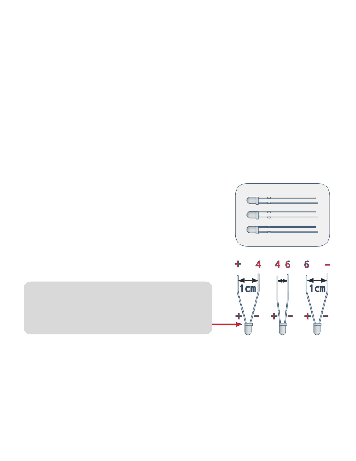
Sensors
varikabi compares the brightness at its three sensors. Depending on how the so-called
phototransistors are aligned, varikabi perceives impressions of the ground, in front or above
itself. A phototransistor (FT) can be imagined essentially as a variable resistor whose
resistance decreases as the brightness increases.
Caution:
The phototransistors must be installed correctly
polarized. The + side has a shorter leg and a
flattening on the protruding collar of the case.
However, you must pay attention to the correct polarity of
the phototransistor. The sensors are connected to the
breadboard in all 12 circuits in the rows +, 4, 6 and -.
Therefore, bend the connections slightly apart according
to the illustration.
The following pages describe how to install the three
sensors for each function. Select a desired function and
align the sensors accordingly.
Page 71
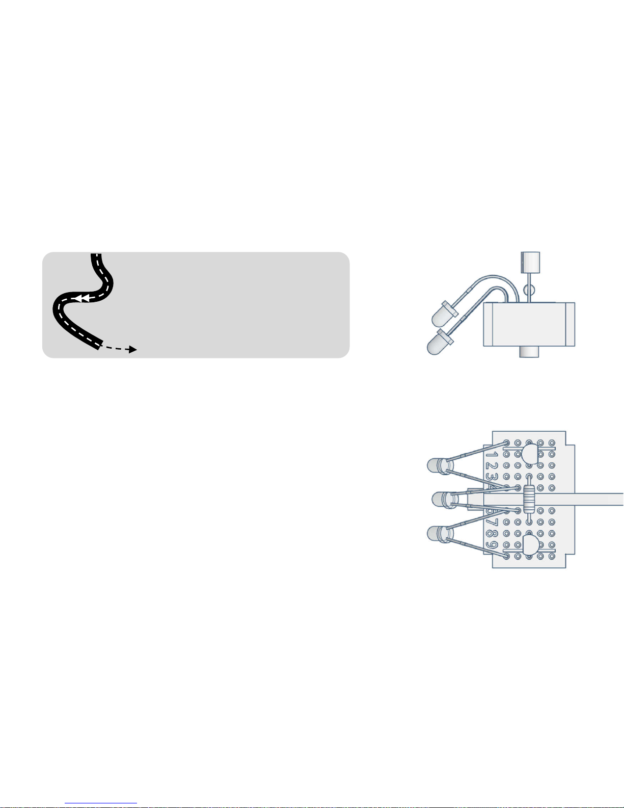
1) Following Dark Lines
• Searches for a dark line
(e.g. black tape)
• Drives along the line
• Accelerates on straight
stretches and brakes in curves
Circuit: Shadow Follower / Acceleration Mode
With the distance between the outer two sensors you
can adjust the accuracy with which varikabi is
supposed to drive on the line. Ideally, they are a little
off the line. If they are too close to the line, varikabi
will permanently adjust the direction and drive
serpentines.
In addition, it will not be able to activate its turbo,
because for this more light must fall on the outer
sensors than on the one in the center.
Page 72
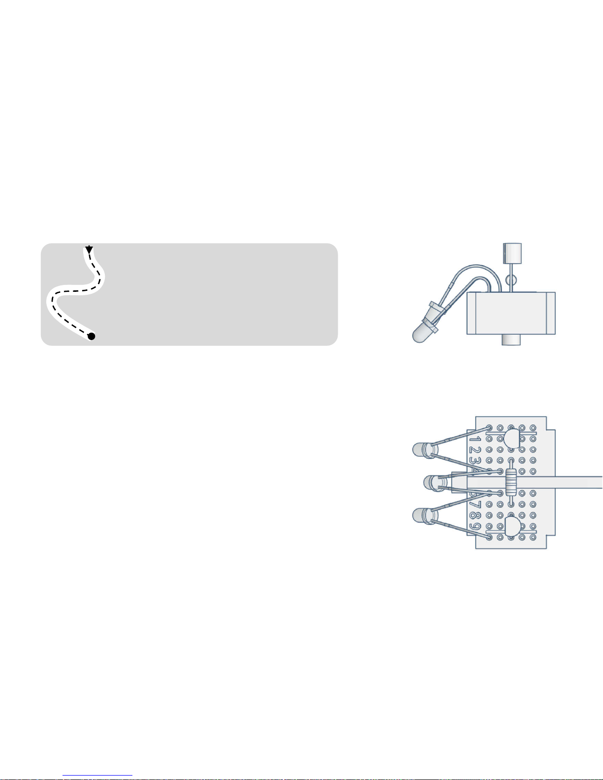
2) Following Light Lines
• Drives along a bright line
(e.g. white tape on a dark
background)
• Stops at the end of the line
Circuit: Light Follower / Braking Mode
If you do not have white adhesive tape, you can place
white sheets of paper on a dark floor, for example.
With the distance between the outer two sensors you
can adjust the accuracy with which varikabi is
supposed to drive on the line.
To make varikabi stop at the end of a line (on a dark
background), direct the center sensor further down
than the two lateral sensors.
Page 73
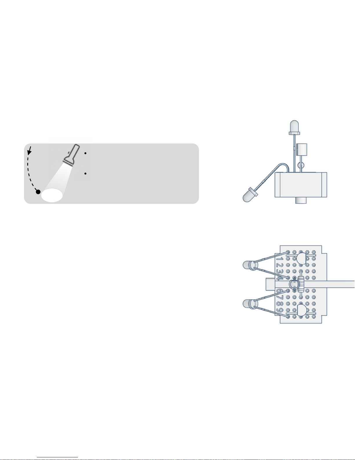
• Traces a light on the ground
or a lamp in front of him
• Stops in front of the light
• Stops when a shadow
appears over him
Circuit: Light Follower / Braking Mode
The ambient light should not be too strong for this
function, so that the contrast is strong enough.
Align the side sensors in parallel or just slightly to the
side so they can simultaneously keep a frontal light in
sight.
The more light hits the outer and the less the center
sensor, the sooner varikabi will come to a standstill.
This ratio can also be adjusted with the inclination of
the center sensor.
3) Tracking Light
Page 74
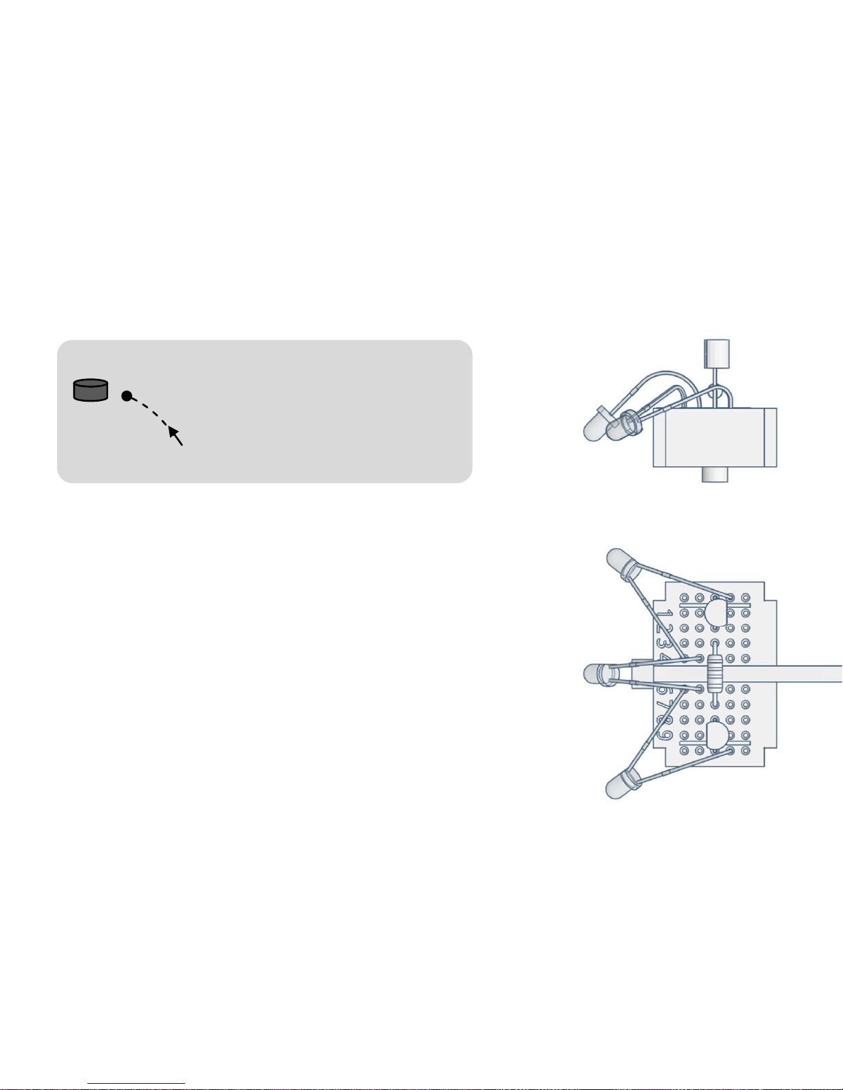
• Moves towards dark objects
in front of him
• Keeps distance and stops in
front of them or tracks
moving objects
Circuit: Shadow Follower / Braking Mode
Adjust the distance of the lateral sensors to the size of
the object to be tracked. The further forward they are
directed, the more exactly varikabi will follow the
object. However, if they are both directed to the
object, varikabi will not be able to stop in front of it.
Use the tilt angle of the center sensor to adjust the
distance to the object being tracked. The more you
point it down, the closer varikabi will approach the
object.
4) Tracking Objects
Page 75
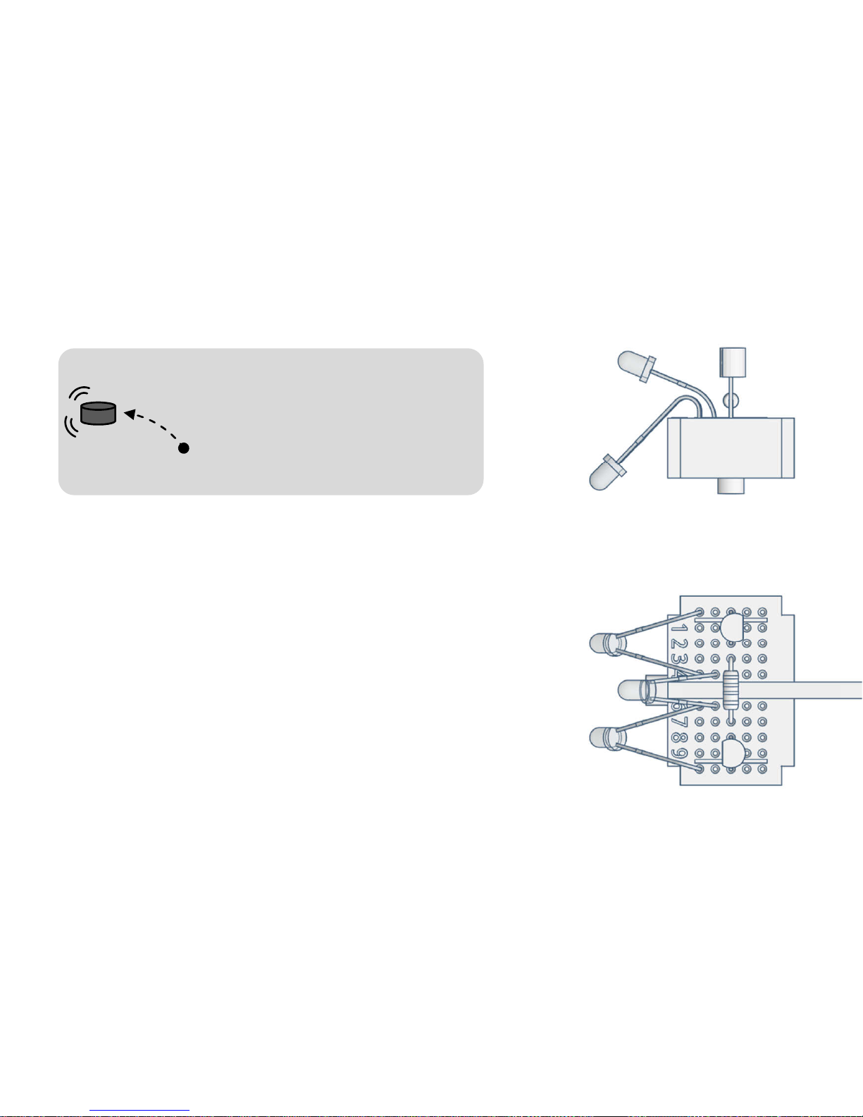
• Stands still when no dark
object is in sight
• Starts moving when an object
is in front and follows it
• pushes small things forward
5) Pushing Objects
Circuit: Shadow Follower / Braking Mode
Adjust the distance of the lateral sensors to the size of
the object to be tracked. Both sensors should have the
object in view at the same time.
Adjust the angle of inclination of the middle sensor so
that it is only slightly over the object. If the middle
sensor points too steeply upwards, varikabi remains
constantly in motion and can only be stopped by a
shadow from above.
Page 76
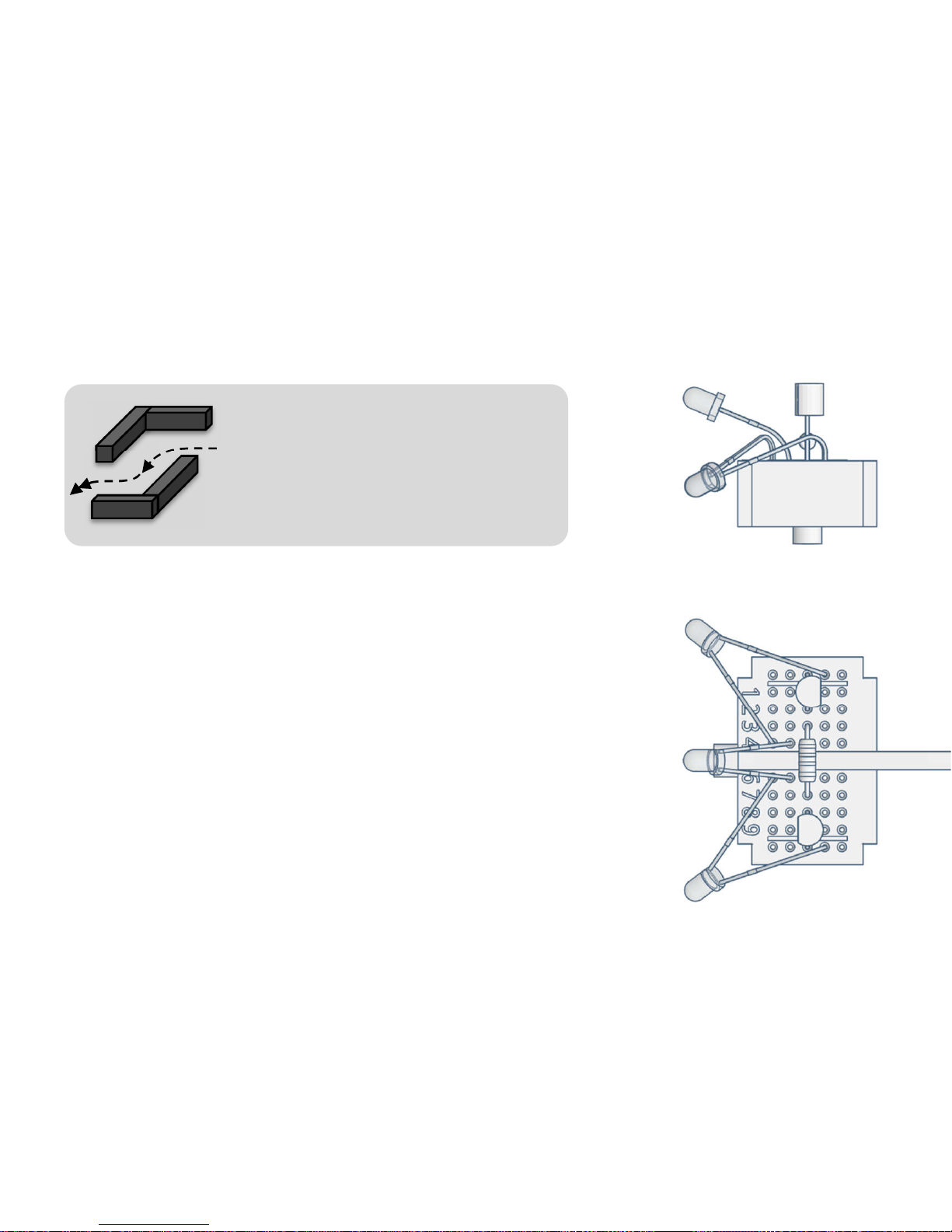
• Stops in case of dark obstacles,
navigates between them and
then accelerates again
• Overcomes an obstacle course
6) Avoiding Obstacles
Circuit: Light Follower/ Acceleration Mode
In order for varikabi to reliably avoid obstacles, these
must be darker than the ground.
Align the lateral sensors about 45° to the side and slightly
to the ground. The further the sensors are directed
downwards, the closer varikabi will approach obstacles
before swerving.
Adjust the tilt angle of the center sensor in the way that it
is only slightly directed above the obstacles so that
varikabi will be able to accelerate on free track.
Page 77
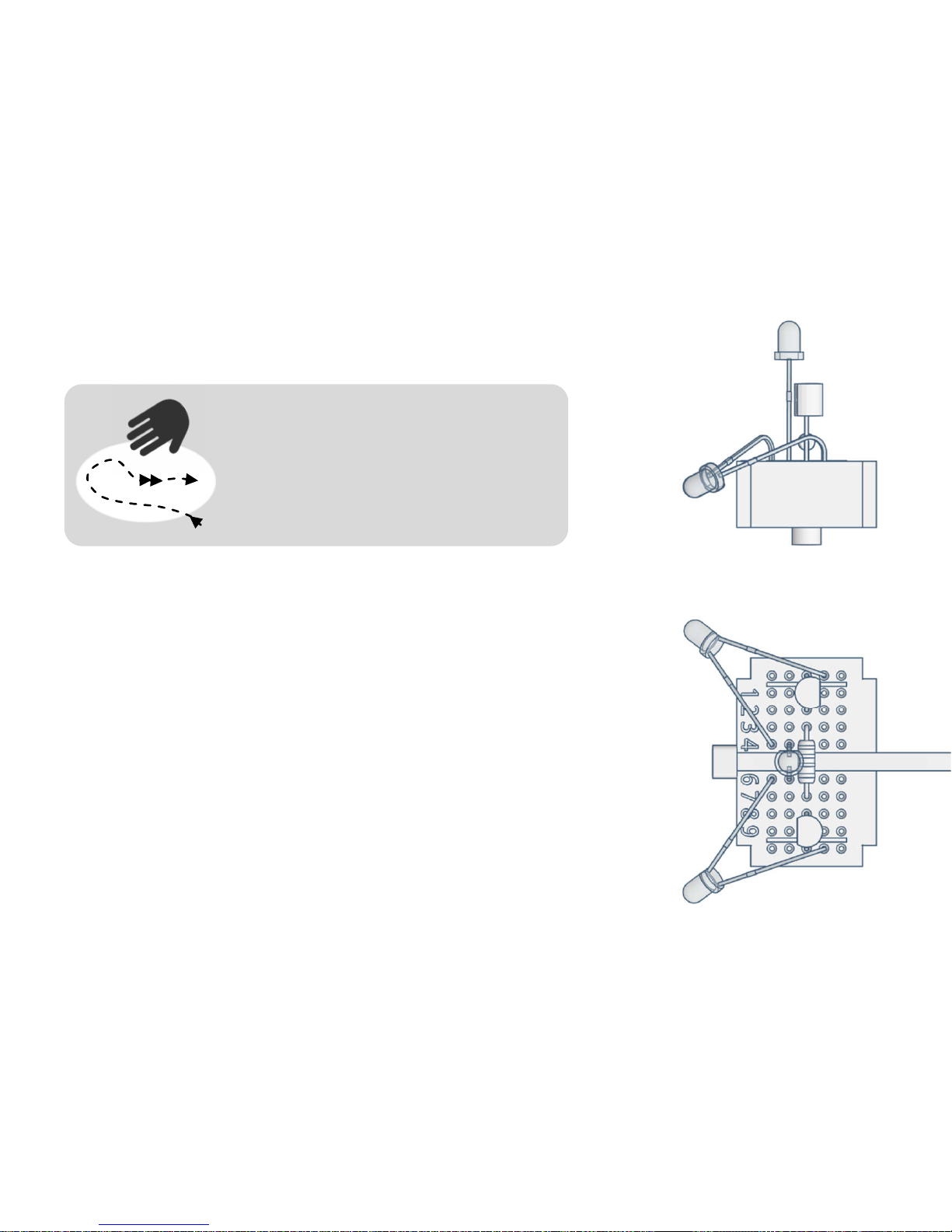
• Stays on a bright surface (e.g.
illuminated table in the dark)
• Avoids dark obstacles
• Accelerates and escapes shadows
appearing over it
7) Avoiding Dark
Circuit: Light Follower/ Acceleration Mode
The bright area can be e.g. your room floor or a clear table
illuminated from above. You can also place white sheets
of paper on a dark background. Avoid lateral light
incidence from windows. For varikabi to recognize the
edge of the table well, the optimum angle of inclination
of the two lateral sensors must be found.
Caution: If you hold your hand above varikabi, it will only
drive straight ahead without paying attention to its
surrounding.
Page 78
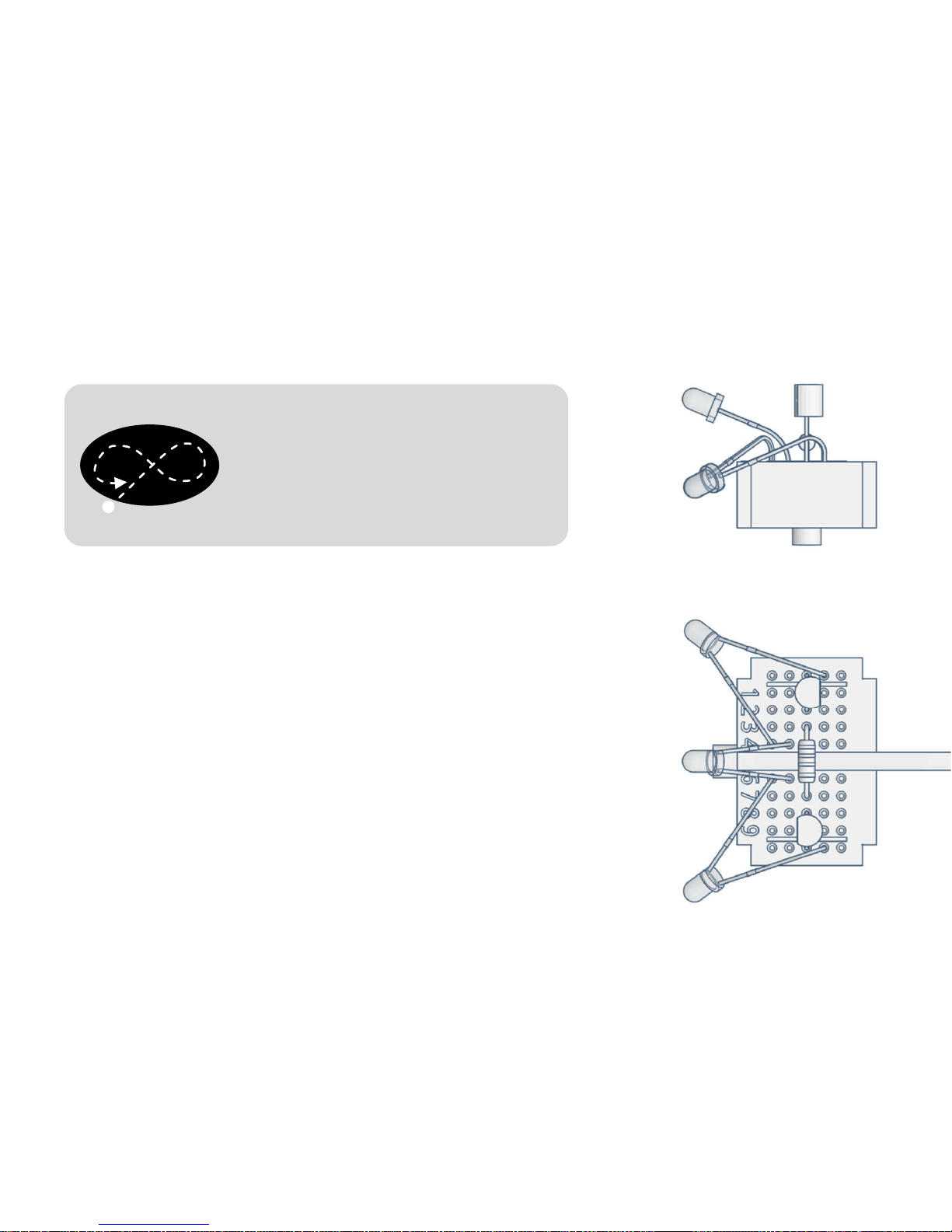
8) Avoiding Light
• Stands still on a light surface
• Drives steadily on a dark ground
• Turns away from light or stops in
front of it
Circuit: Shadow Follower / Braking Mode
For the dark background, for example, you can cut black
paper and place it on a light floor. The surface should be
round and have a diameter of at least 30 cm.
Adjust the inclination of the two lateral sensors in the way
that varikabi will turn at the edge in time.
Adjust the tilt angle of the middle sensor in the way that
varikabi will always keep moving on the dark surface but
stops on a light surface.
Page 79
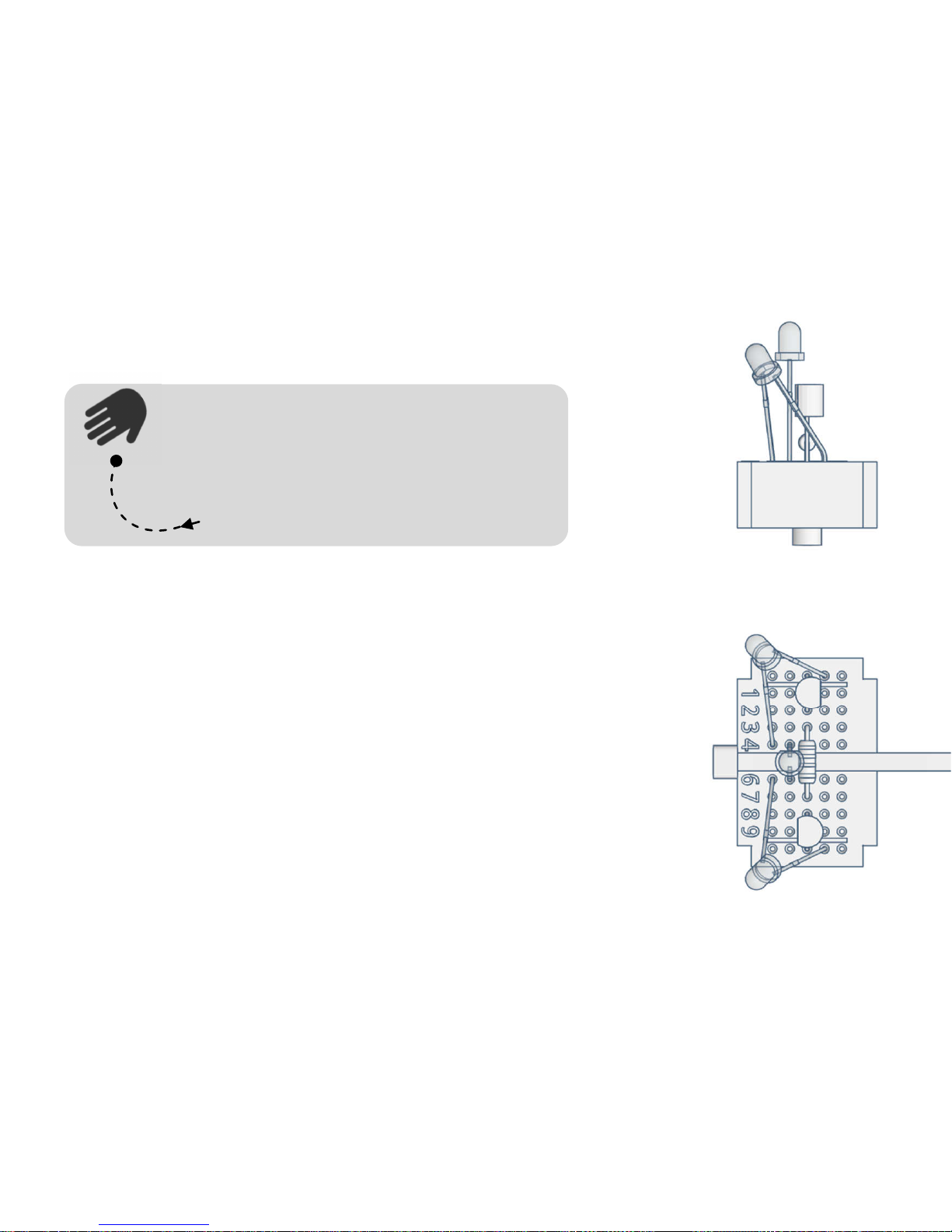
9) Following Shadows
• Avoids light and seeks shade
• Drives towards a shadow
• Stops in the shadow
• Tracks the shadow as it moves
Circuit: Shadow Follower / Braking Mode
Choose a place outdoor or underneath a light source,
which is placed at least one meter high. Your hand is the
best shadow. However, be careful not to wear clothes
with dark sleeves, otherwise varikabi would prefer to
follow the shadow of your arm.
When you hold your hand over varikabi, it stops. Then
slowly move your hand forwards or sideways so that
varikabi can follow it.
Page 80
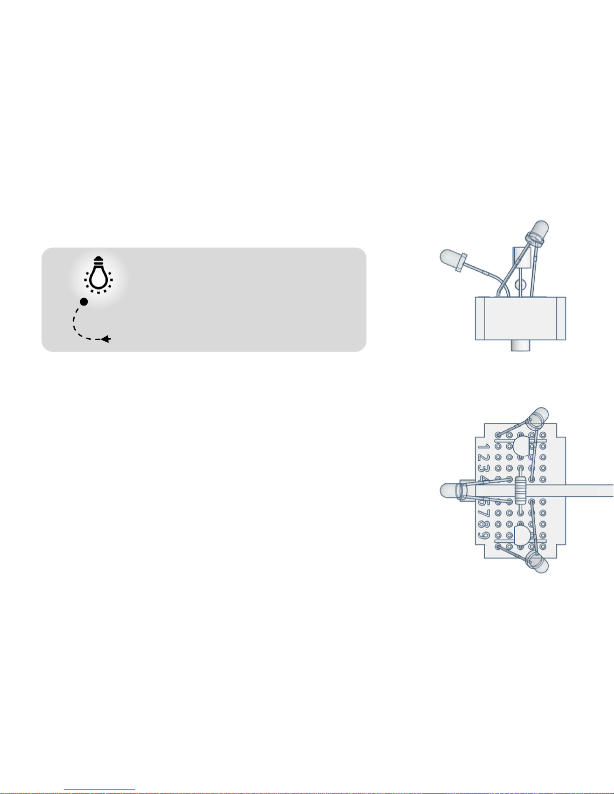
10) Search Light
• Searches for a light above him
and drives towards it
• Stops under the light
• Turns away of shadow and drives
back into the light
Circuit: Light Follower / Braking Mode
For this experiment you need a dark room and a lamp
about 30 to 100 cm above varikabi. Ideally, you can also
move the lamp. However, a flashlight is not very suitable
because of its focus.
The more you direct the center sensor upwards, the
further varikabi will move towards the center of the lit
area before it stops. If you hold your hand between
varikabi and the lamp, varikabi will try to return into the
light.
Page 81
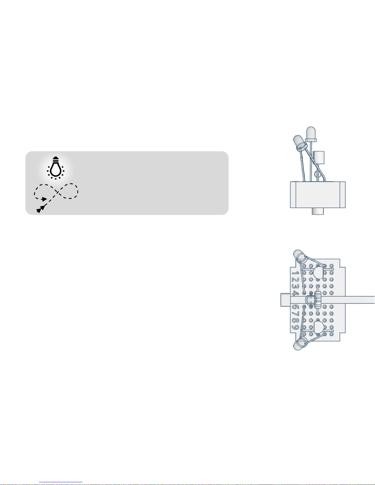
11) Circling Around Light
• Looks for a light and drives fast
towards it
• Then below the light it moves on
slowly in circles
• Accelerates when shadow is above
Circuit: Light Follower/ Acceleration Mode
For this experiment you need a dark environment and a
lamp about 30 to 100 cm above varikabi. A flashlight is not
suitable because of its strong focus.
If you place varikabi on the ground in some distance from
the lamp, it will quickly approach the light.
Below the lamp, it will slow down and keep turning in
order not to move away from the lamp. With the inclination
of the sensors you choose at which distance varikabi will
make the turn.
Page 82
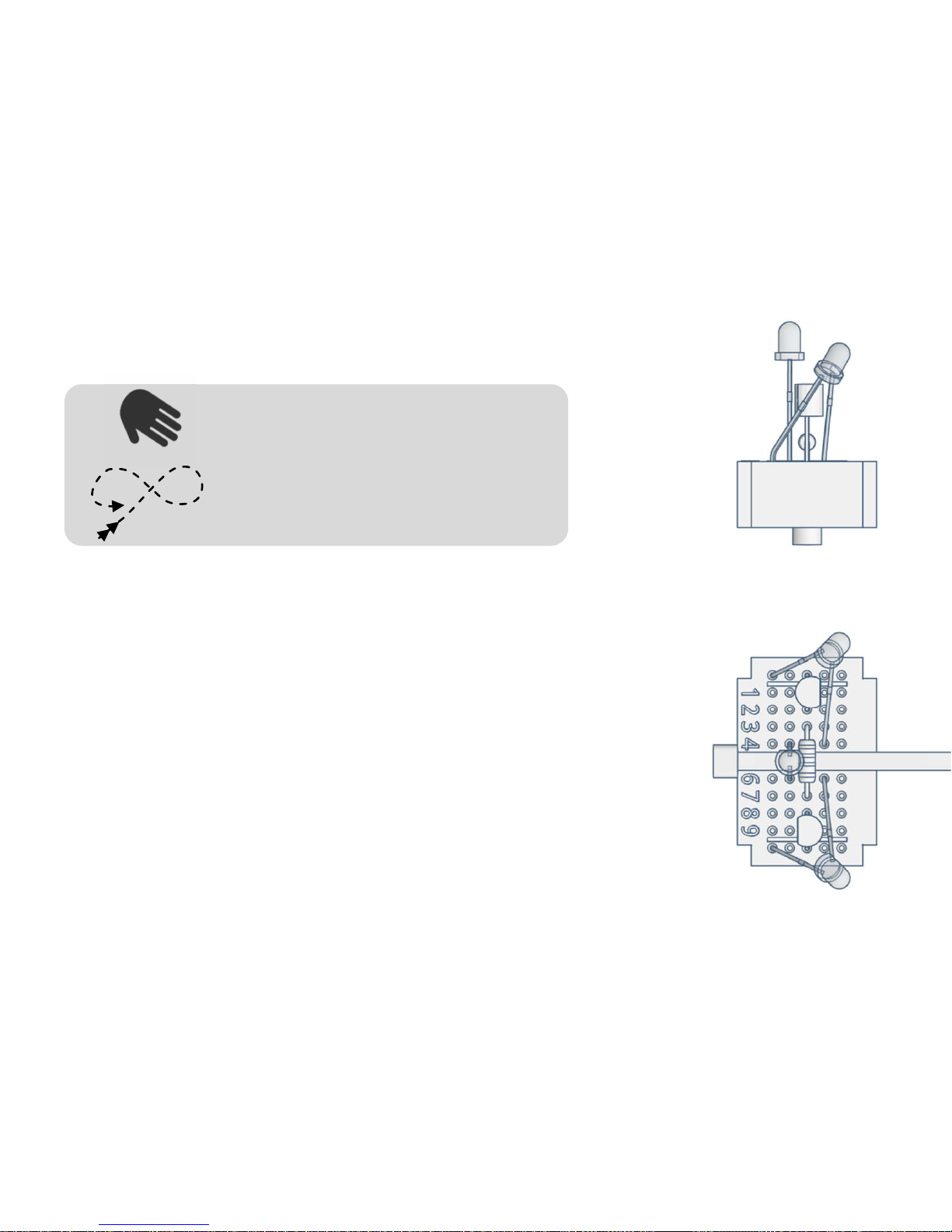
12) Circling Around Shadow
• Turns away from light
• Accelerates when shadow is
above
• Tries to stay in the shade and
turns again and again
Circuit: Shadow Follower / Acceleration Mode
Choose a place outdoors, but not in the sun, or a room
with uniform ceiling lighting. If you hold your hand or a
larger object over varikabi, it will accelerate briefly and
then turn steadily in order not to move out of the shadow.
With the inclination of the sensors you set when varikabi
will turn back each time. The two side sensors must
always be directed slightly further backwards than the
center sensor.
Page 83
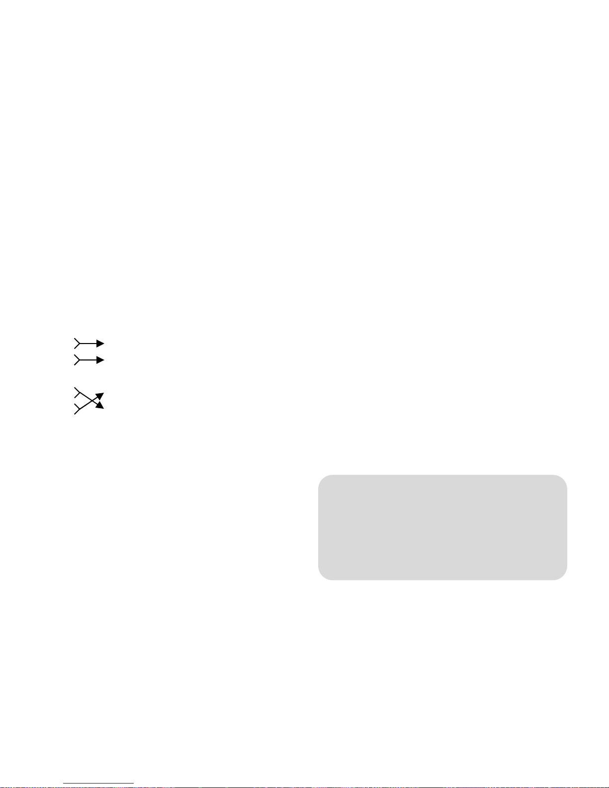
Cable Bridges
The blue cables connect the sensors (FT2,
FT3, FT1) with the transistors (T2,T1).
Depending on whether you connect them
directly or crossed, varikabi will respond
differently to a shadowing of the sensor FT3:
FT
2
FT
3
FT
1
FT
2
FT
3
FT
1
The description of the 12 functions indicates
whether you need to select the acceleration
mode or the braking mode for each circuit.
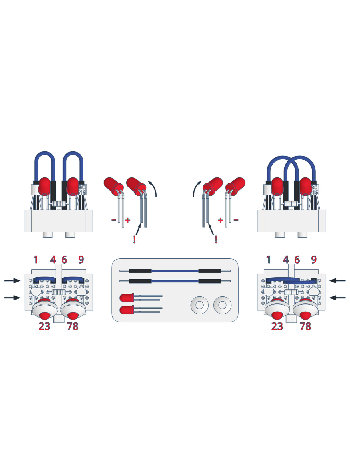
Plug the blue wires into rows 1, 4, 6 and 9
according to the illustration.
Acceleration mode: cables parallel
Braking mode: cables crossed
LEDs
Unlike incandescent bulbs, LEDs must be
properly polarized for them to light up. The
shorter leg and the flattening on the
housing mark the negative connection (–) of
an LED.
Depending on the color you have two red,
blue or green LEDs in your assembly kit.
Depending on whether you have selected
the braking mode or the acceleration mode,
the LEDs must be bent and plugged-in in a
different way.
Finally, put the two white silicone sheaths
on the LEDs.
Note:
varikabi's eye-LEDs will only light up at
high speed or at standstill. This means
always when the center sensor FT3 is
shaded.
T
2
T
1
varikabi gets faster
T
2
T
1
varikabi slows down
Page 84
Acceleration Mode Breaking Mode
Page 85

Connection of the Motors
varikabi moves with the help of two
particularly slow and quiet DC motors. With
the black rubber caps varikabi therefore
requires neither a gear nor wheels.
The speed of the motors is set by the level
of the applied voltage. This voltage is
controlled with the help of the transistors or
the sensors respectively.
Depending on which transistor (T2, T1) drives
which one of the motors (M2, M1), the
following behaviors arise:
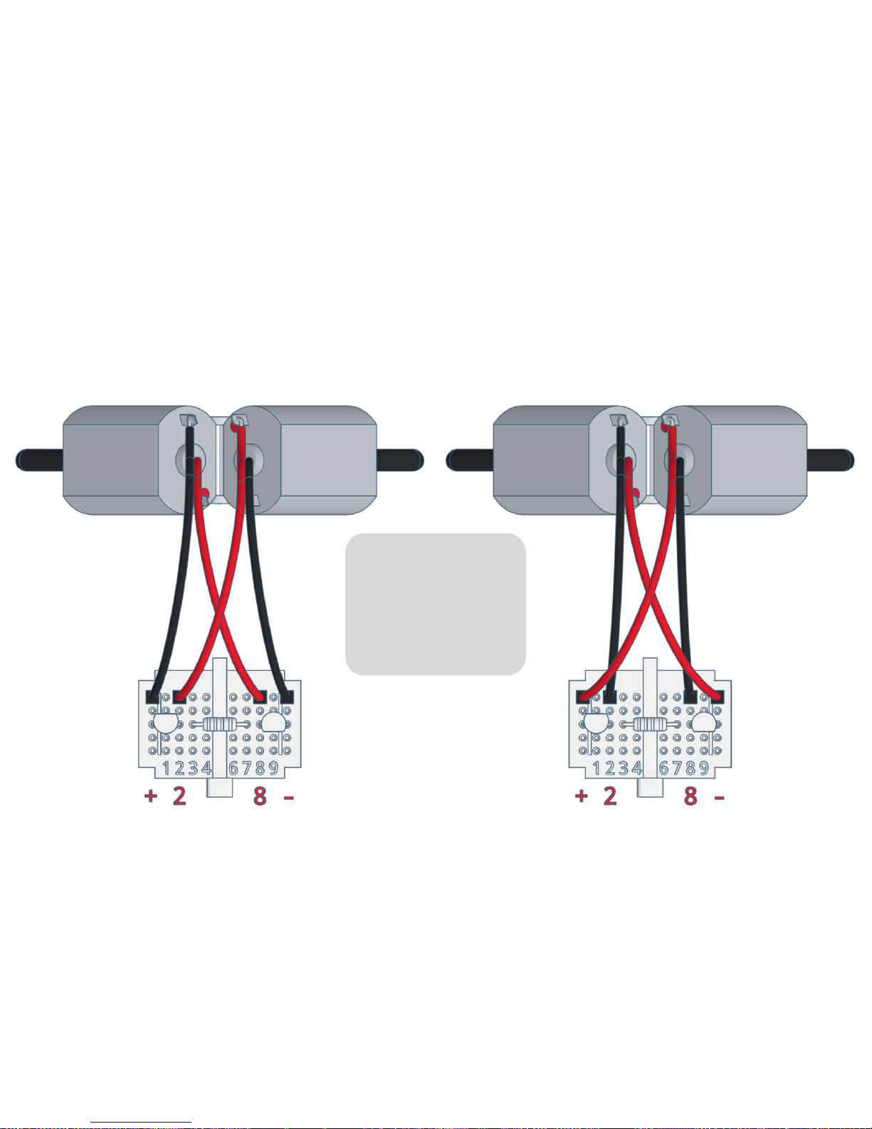
The following diagram shows how the
cables are to be mounted in the rows + 2 8
–. Depending on the selected function,
connect the motor cables as light or shadow
follower.
Light Follower: red cables are inside
Shadow Follower: red cables are outside
The rotation direction of the motors depends
on the polarity of the applied voltage. In
order for varikabi's engines to spin forward,
make sure that the red connections always
cross and the black ones run parallel.
Note:
By connecting the motors differently,
you determine whether varikabi will be
driving toward the dark or the light.
T
2
M
2
T
1
M
1
Light Follower
T
2
M
2
T
1
M
1
Shadow Follower
Page 86
Light Follower Shadow Follower
Caution:
The red cables
are crossed
connected!
Page 87
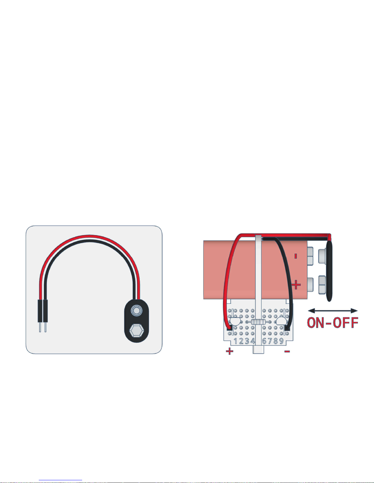
Power Supply
In order to put varikabi into operation, the
outer two rows of the breadboard now
have to be supplied with power.
To do this, lead the battery cable with the
two plug-in connections from underneath
through the gap between the bracket and
the battery.
Then insert the contacts of the battery cable
to the positions on the breadboard indicated
below. To avoid a short circuit between the
plugs, leave them in the breadboard and
use the clip connector on the battery to turn
varikabi on and off. For a battery change,
you can pull out the battery sideways.
Page 88

Fault Diagnosis
Problem Possible Reasons
varikabi does not move at all. • The left and right sensors are connected with the
wrong polarity.
• A battery cable is not inserted correctly in the
breadboard or the battery clip is not on the 9V
battery.
• The battery is empty or defective.
• The rubber caps are too far on the motor shafts.
Only one of the motors is running. • The left or the right sensor is connected to the
breadboard with the wrong polarity.
• A transistor is connected to the breadboard with
the wrong polarity.
• A connection cable of the motor is not inserted
correctly in the breadboard.
• A rubber cap is pushed too far on the motor shaft.
A motor turns backwards. • This motor is connected with the wrong polarity.
Page 89

Problem Possible Reasons
varikabi only drives straight
ahead.
• The center sensor is connected incorrectly.
The two LEDs do not light up. • One or both LEDs are inserted with the wrong
polarity.
varikabi gets stuck on the ground. • varikabi is not placed well or too uneven on the
cable ties.
• The surface is too bumpy for varikabi.
If none of these causes apply to your problem, check carefully that all components are
installed as described in the construction plan.
If you need help, please contact us with a detailed error description and preferably a
photo of your robot:
Page 90

3) Operating Principle
Depending on how the sensors are connected to the transistors and which motor is driven by
which transistor, there are four basic control and circuit variants, which are shown on the
following pages.
• Acceleration mode / Shadow Follower
• Acceleration mode / Light Follower
• Braking mode / Shadow Follower
• Braking mode / Light Follower
All other features of the 12 functions are set by aligning the sensors.
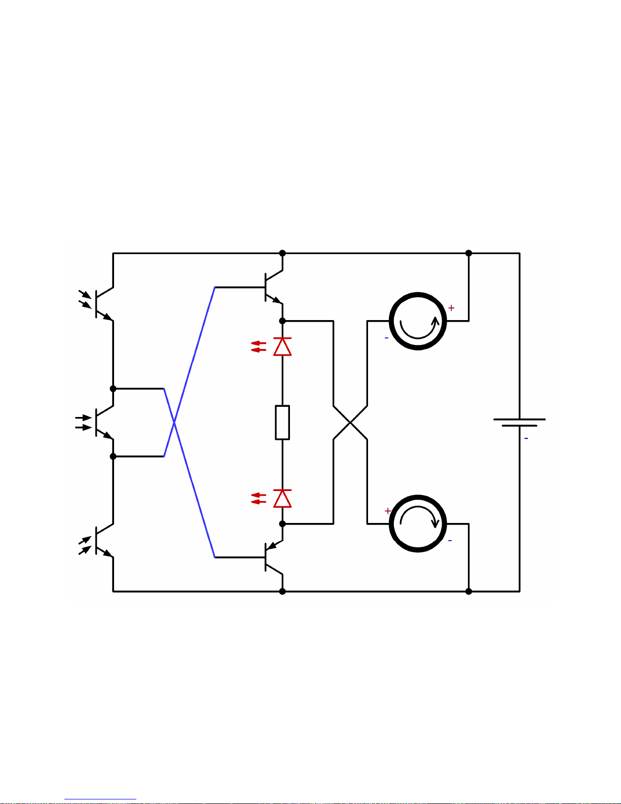
The obliquely drawn connections represent the blue cable bridges between the sensors and the
transistors.
The two LEDs are connected in series with the resistor and arranged between the transistors. In
Acceleration mode they light up when the current flows through both transistors. In Braking
mode they light up when the current flows through the motors in the other direction, as long
as they stand still.
Page 91
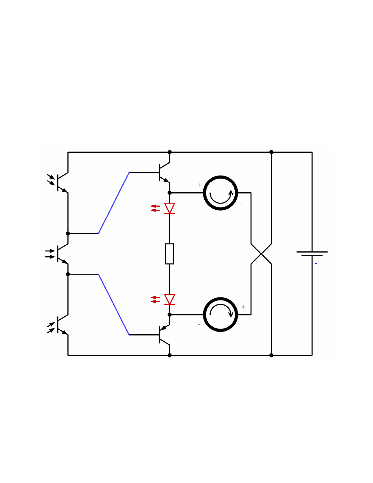
Circuit: Acceleration Mode/ Shadow Follower
FT
2
FT
3
FT
1
T
2
T
1
L
2
L
1
M
2
M
1
R
Bat+9 V
Page 92
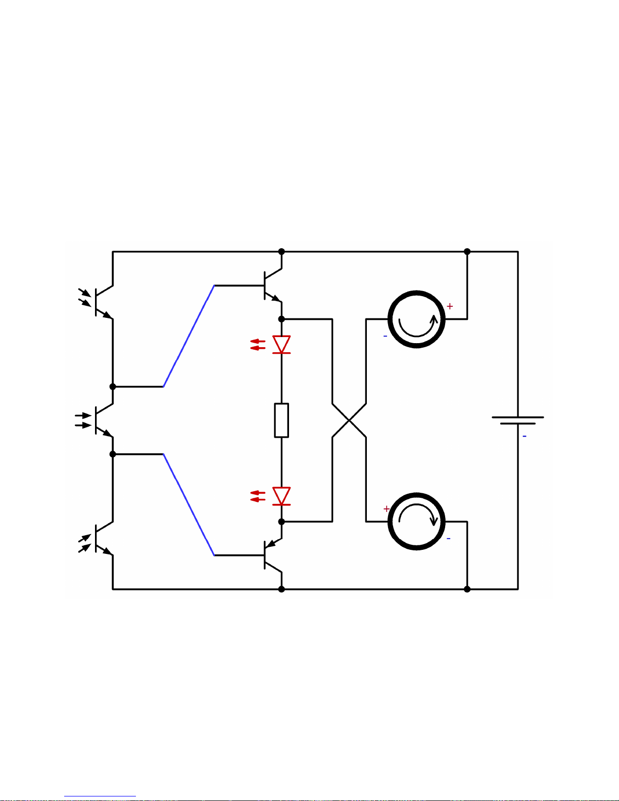
Circuit: Acceleration Mode/ Light Follower
FT
2
FT
3
FT
1
T
2
T
1
L
2
L
1
R
Bat+9 V
M
2
M
1
Page 93
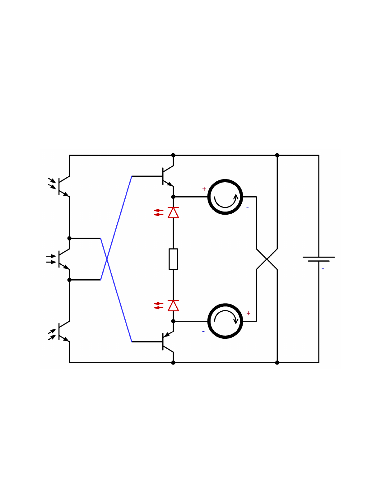
Circuit: Braking Mode/ Shadow Follower
FT
2
FT
3
FT
1
T
2
T
1
L
2
L
1
M
2
M
1
R
Bat+9 V
Page 94
Circuit: Braking Mode/ Light Follower
FT
2
FT
3
FT
1
T
2
T
1
L
2
L
1
M
2
M
1
R
Bat+9 V
Page 95
The Transistors
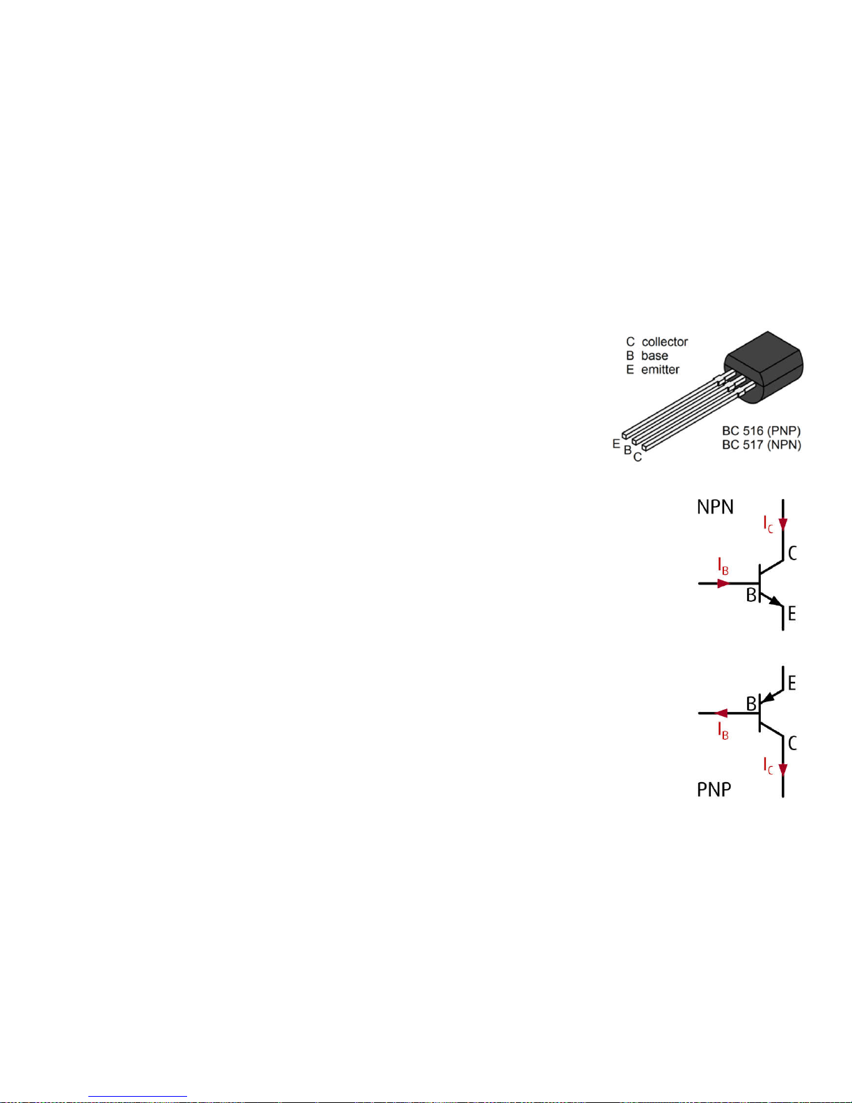
A transistor is a simple electronic amplifier with three connections:
base (B), emitter (E) and collector (C).
At a sufficiently high voltage of about UBE= 0.7 V (V = Volt) between
base and emitter, the transistor reduces the resistance between
collector and emitter and - it is said - it switches through. The
collector current IC for ordinary transistors can be about 100 to 800
times larger than the base current IB.
varikabi uses Darlington transistors with a very high current amplification of
30 000. To supply the motor and LEDs with a current of 0.03 A (amps) = 30
mA (milliamperes), a base current of only 1 μA (microampere) is required:
30 mA / 30.000 = 0.001 mA = 1 µA
A Darlington transistor consists of two transistors connected in series and
requires about U
BE
=1.4 V instead of 0.7 V to switch through. To ensure that
the motors react to the sensor signals in opposite directions, varikabi uses a
complementary pair of transistors:
one PNP transistor for T1 (BC516) and one NPN transistor for T2(BC517)
I
C
I
B
I
B
I
C
T
2
T
1
Page 96
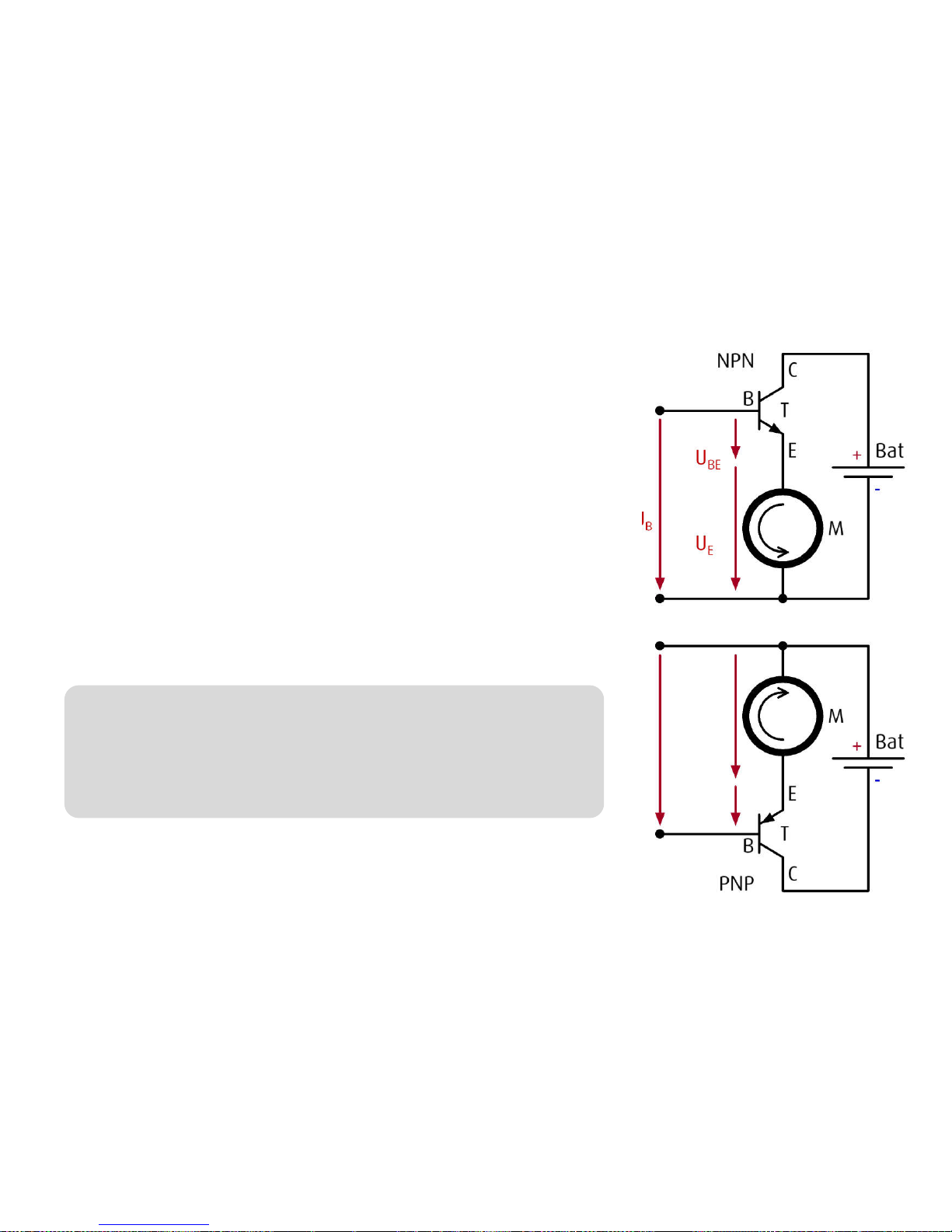
The adjacent figure shows a simple circuit with a battery, a
motor and an NPN transistor. Underneath, the corresponding
circuit is shown with a PNP transistor. The current flows in the
direction of the black arrow from plus to minus in both cases.
There are three different basic circuits with a transistor.
varikabi uses the so-called collector circuit.
It is called collector circuit because the collector (C) is
connected to a constant voltage (battery).
The red arrows symbolize the voltages. You can notice that
the voltage at the motor UEis lower by the base-emitter
voltage UBEthan the base-voltage UB.
UE= UB– UBE= UB– 1.4 V
U
BE
U
B
U
E
Note:
Because the voltage at the emitter (E) follows the
voltage at the base (B) except for the difference
of UBE, this circuit is also called emitter follower.
With the control voltage UBand a very low current IB, the
voltage UEand thus the speed of the motor can be controlled.
U
E
U
B
U
BE
Page 97
The Sensors
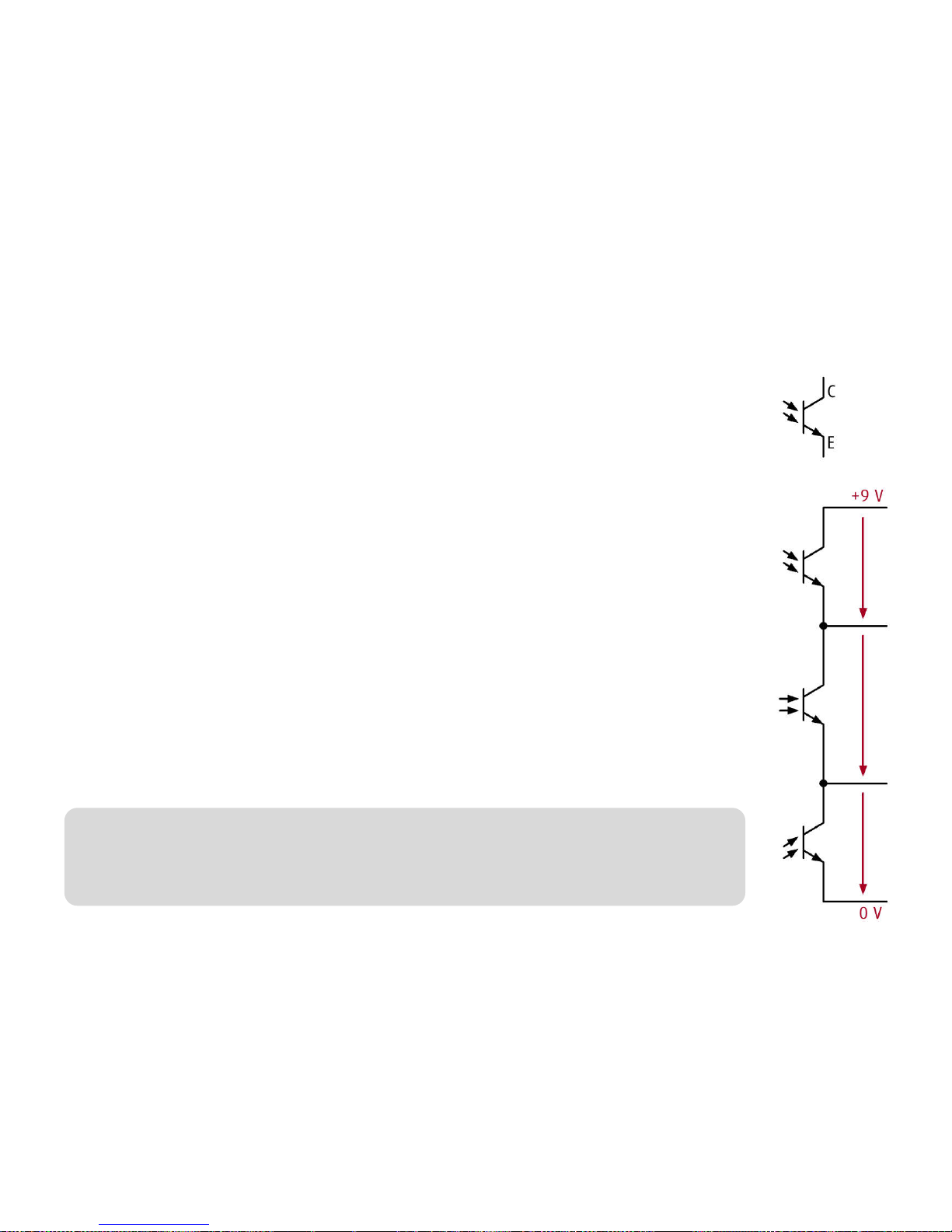
varikabi's phototransistors (FT) are similar in design to a transistor. The
collector (C) is on the plus side and the emitter (E) is on the minus side.
Instead of a basic connection, however, they have a light-sensitive area.
The incidence of light determines the permeability between the collector and
the emitter.
The circuit diagram shows that the three phototransistors FT1, FT3and FT2are
all connected. They say they're in series. This series connection results in a socalled voltage divider, which divides the voltage of the 9 V battery depending
on the illumination of the sensors.
Examples:
• With exactly the same amount of light, the voltages at the sensors are
three volts each, regardless of the brightness: U2= U3= U1= 3 V
• If, for example, the middle sensor FT3were illuminated four times brighter
than FT2and FT1, a voltage four times lower would drop at FT3and the
supply voltage would be divided as follows: U2= 4 V, U3= 1 V, U1= 4 V
Note:
The two variable voltages between the three sensors control the speed of
the two motors.
FT
2
U
2
FT3U
3
FT
1 U1
 Loading...