

Page 1

Page 2

VARI❋LITE® is a trademark owned by Ge nlyte Thomas Group LLC and is regi ste re d in t he United States and other countr ie s.
™
VL1000™, VL2000™, VL2201™, VL2202™, VL2400™ (and the individual product designations), VL3000™, Series 1000
Series 3000
™
, DICHRO❋TUNE™, VARI❋IMAGE™, and the Vari-Lite Ast erisk are also trademarks owned by Genlyte Thomas Group LLC.
, Series 2000™,
VARI❋LITE® products are prot ec te d by one or more of the following patents, and other pending patent app lica ti ons worldwide:
U. S. Patents No. 6,123,436; 6,113,252; 6,046,861; 6,031,749; 6,011,640; 5,969,868; 5,959 ,7 68; 5,9 34, 794; 5,882,107; 5,829,868; 5,825,548; 5,798,619;
5,774,273; 5,769,527; 5,758,956; 5,728,994; 5,640,061; 5,590,954; 5,454,477; 5,432,691; 5,367,444; 5,329,431; 5,307,295; 5,282,121; 5,278,742; 5,209,560;
5,186,536; 5,073,847; 5,01 0, 459; 4,980,806; 4,972,306; 4,8 00, 474; 4,779,176; 4,701,833; 4,602, 321;
U. S. Design Patents No. 439,356; 420 ,332; 417,300; 415,301; 413,995; 377,338; 366,712; 359,574; 350,408; 347,113;
Australia Patents No. 693,691; 683, 695; 667,109; 649,264; 646,588; 586, 095; 576,400;
Australia Design Patents No. 128,796; 128 ,7 95;
Canada Patents No. 2,070,670; 2,050,375; 1,270,675; 1,259,058;
Canada Design Patents No. 81,234; 81 ,2 33; 76, 046;
European (UK) Patents No. 0 652 400; 0 586 049; 0 565 218; 0 547 732; 0 534 710; 0 495 305; 0 474 202; 0 379 970; 0 253 082; 0 253 081; 0 248 974; 0 192
882;
Germany Patents No. 694 25 943.8; 693 14 122.0; 692 08 615.3; 692 07 692.1; 691 31 478.0; 691 21 029.2; 690 33 385.4; 37 89 166.9; 37 68 727.1; 37 51
804.6; 37 50 201.8; 35 87 270.5;
Germany Design Patents No. M 98 01 745.4; M 96 04 515.9; M 96 04 514.0; M 94 07 689.8; M 94 02 951.2; M 499 03 583.6; M 498 11 203.9; G 93 12 884.3;
Spain Patents No. 2 090 191; 2 084 289; 2 020 96 0; 0 548 328;
Spain Utility Model Patent No. 2.031. 74 8;
Spain Design Patents No. 0.137.502; 0.1 37.501; 0.133.573;
Greece Patent No. 910.400.544;
Japan Patents No. 2,843,696; 2,059,669; 2,055,324; 2,002,168; 1, 96 6,5 25; 1,889,481; 1,792,721; 1,770, 241;
Japan Design Patents No. 985,98 5-1; 985,985; 947,552; 945,436-1; 945, 436; 1,106,089; 1,077,598; 1,072,598; 1,060,414; 1,002,123 ;
Korea Patents No. 76,310; 42,639; 28 3, 770; 181,180;
Korea Design Patents No. 209,896; 209, 895;
Mexico Patent No. 180,148;
Taiwan Patents No. 78,726; 66,975; 65,380; 28,275;
United Kingdom Design Registrations No. 2082526; 2072562; 2056387; 2056386; 2042174; 203 8212; 2033108; 2029499.
All other brand or product na m es which may be mentioned in this m anual are trademarks or reg ist ere d trademarks of their respec tive companies or
organizations.
Vari-Lite
A Division of Genlyte Thomas
10911 Petal St. Dallas
TX 75238
This manual is for informat io nal use only and is subject to change wit hout notice. Genlyte Thomas assu mes no responsibility or liabil ity for any claims
resulting from errors or inaccuracies that may appear in this manual.
Version as of: 20-Aug- 03
Part number: 02.9678.000 1 A
VL3000™ Series Luminaire User’s Manual
©2003 Genlyte Thom as G roup LLC. All Rights Reserved.
Page 3

How To Obtain Warranty Service
A copy of the Vari-Lite Limited Warranty was included in the shipping package for this
VARI❋LITE® product.
T o obtain war ranty servi ce, please con tact custome r service at 1-877-VARI-LITE (1-877-827-4548) or
[email protected] and request a Return Material Authorization (RMA) for warranty
service. You will need to provide the model and serial number of the item being returned, a
description of the problem or failure and the name of the registered user or organization. If available,
you should have your sal es invoi ce to es tabl ish the date of s ale as the begi nning of the warrant y peri od.
Once you obtain the RMA, pack the unit in a secure shipping container or in its original pack ing box.
Fill out the RMA form included at the end of thi s manu al and place in shipping container along wit h a
copy of your invoice (if available). Write the RMA number legibly on or near the shipping address
label and return the unit, freight prepaid to:
Vari-Lite
10911 Petal St.
Dallas, TX 75238
Attention: Warranty Service
FOREWORD
As stated in the warranty, it is required that the shipment be insured and FOB our service center.
02.9678.0001 A 20-Aug-03 i
Page 4

VARI❋LITE® - VL3000™ SERIES LUMINAIRE USER’S MANUAL
Compliance Notice
FCC
This equipment has been tested and found to comply with the limits for a Class A digital device
pursuant to Part 15 of FCC Rules. These limits are designed to provide reasonable protection against
harmful interference when this equipm ent is operated in a commercial environme nt. This equipment
generates, uses, and can radiate radio frequency energy and, if not installed and used in accordance
with Vari-Lite system, service, and safety guidelines, may cause harmful interference to radio
communications. Operation of this equipment in a residential area is likely to cause harmful
interference, in which case the user will be required to correct the interference at his/her own expense.
Declaration of Conformity
We declare, under our sole responsibility, that this product complies with the relevant clauses of the
following standards and harmonized documents:
Safety
EN 60598-1:1997 Luminaire Safety Standard, General Requirements
EN 60598-2 17:1989 Specification for Luminaires for Stage and Studio Lighting
EMC
EN 55022A:1994 Radiated and Conducted Emissions
EN 50082-1:1997 Generic Immunity Standard
We certify that the product conforms to the protection requirements of council directives: 73/23/EEC
(LVD) and 89/336/EEC (EMC)
ii 20-Aug-03 02.9678.0001 A
Page 5

Safety Notice
It is extremely importan t to read ALL safety information and instruc tions provided in this manual and
any accompanying documenta tion before ins tallin g and operati ng the product s describ ed herein. Heed
all cautions and warnings during installation and use of this product.
Safety symbols used throughout this manual are as follows:
GENERAL INFORMATION PER TAINING TO PROTECTION AGAINST ELECTRICAL SHOCK,
FIRE, EXPOSURE TO EXCESSIVE UV RADIATION, AND INJURY TO PERSONS CAN BE
FOUND BELOW.
WARNING:
INSTRUCTIONS FOR CONTINUED PROTECTION AGAINST FIRE
1. VARI❋LITE® luminaires have been designed for use with specific lamp types. The VL3000
series luminaire requires an Osram HMI 1200 W/S metal halide lamp. Installing another type of
lamp may be hazardous.
2. Luminaires may be mounted on any ty pe of surfa ce as long as mounting inst ructions are foll owed.
See instructions detailed in this manual .
3. Note distance requirement from combustible materials or illuminated objects for VARI❋LITE®
luminaires.
FOREWORD
CAUTION advising of potential damage to product.
WARNING advising of potential injury or death to persons.
WARNING:
INSTRUCTIONS FOR CONTINUED PROTECTION AGAINST ELECTRICAL SHOCK
1. VARI❋LITE® luminaires are designed for dry locations only. Exposure to rain or moisture may
damage luminaire.
2. Disconnect power before servicing any VARI❋LITE® equipment.
3. Servicing to be performed by qualified personnel only.
02.9678.0001 A 20-Aug-03 iii
Page 6

VARI❋LITE® - VL3000™ SERIES LUMINAIRE USER’S MANUAL
WARNING:
INSTRUCTIONS FOR CONTINUED PROTECTION AGAINST EXCESSIVE EXPOSURE
TO UV RADIATION
1. Many VARI❋LITE® luminaires use a lamp that produces UV radiati on. DO NOT look directl y at
lamp.
2. It is hazardous to operate luminaires without lens or shield. Shields, lenses, or ultraviolet screens
shall be changed if they have become visibly damaged to such an extent that their effectiveness is
impaired. For example, by cracks or deep scratches.
WARNING:
INSTRUCTIONS FOR PROTECTION AGAINST INJURY TO PERSONS
1. Exterior surfaces of the luminaire will be hot during operation. Use appropriate safety equipment
(gloves, eye protection, etc.) when handling and adjusting hot equipment and components.
2. Luminaires will have a hot lamp when operating. Di sconnect p ower and al low lamp to cool before
replacing.
3. Arc lamps emit ultraviolet radiation which can cause serious skin burn and eye inflammation.
Additionally, arc lamps operate under high pressure at very high temperatures. Should the lamp
break, there can exist a danger of personal injury and/or fire from broken lamp particles being
discharged.
4. Wear eye protection when relamping.
5. Appropriate safety equipment (gloves, eye protection) should be used when handling damaged
lamps.
6. If lamp is touched with bare hands, clean lamp with denatured alcohol and wipe with lint-free
cloth before installing or powering up the luminaire.
7. The lamp shall be changed if it has become damaged or thermally deformed.
WARNING:
RF INTERFERENCE
1. This is a Class A product. In a domes tic envir onment this pr oduct may cause radio inte rference , in
which case, the user may be required to take adequate measures.
ARC LAMP CHARACTERISTIC CONSIDERATIONS
1. Arc lamps require a period of time to relight after a power interruption or a severe voltage dip. In
some cases, lamp will a utomati cally re light after it has coo led dependi ng on Lamp Power -Up S tat e
configuration setting.
2. Burning position is Universal.
iv 20-Aug-03 02.9678.0001 A
Page 7

Sicherheitshinweise
Es ist äußerst wichtig, ALLE Sicherheitsinformationen und -hinweise in diesem Handbuch und dem
beiliegenden Informationsmaterial zu lesen, bevor Sie die hierin beschriebenen Produkte installieren
bzw. bedienen. Halten Sie bei der Installation und dem Einsa tz dieses Produkts alle Warnhinweise und
Vorsichtsmaßnahmen ein.
Folgende Sicherheitssymbole werden in diesem Handbuch verwendet:
VORSICHT - weist auf möglichen Produktschaden hin.
WARNUNG - weist auf mögliche Körperverletzung und Lebensbedrohung hin.
NACHSTEHEND FINDEN SIE ALLGEMEINE HINWEISE ÜBER
SICHERHEITSVORKEHRUNGEN GEGEN ELEKTROSCHOCK, FEUER, ÜBERHÖHTE UVSTRAHLUNG UND KÖRPERVERLETZUNGEN.
WARNUNG:
HINWEISE ZUM FEUERSCHUTZ
1. VARI❋LITE®-Scheinwerfer sind ausschließlich für den Einsatz mit bestimmten Lampentyps.
Achten Sie auf den Lampentyp (Osram HMI 1200 W/S metal halide lamp), bevor Sie die
jeweiligen Lampen ersetzen. Die Installation eines anderen Lampentyps kann gefährlich sein.
2. Scheinwerfer können auf jeder beliebigen Oberfläche montiert werden, solange Sie die
Montageanweisungen befolgen. Detaillierte Hinweise finden Sie in diesem Handbuch.
3. Beachten Sie die Einhaltung des erforderlichen Sicherheitsabstandes der VARI❋LITE®-
Scheinwerfer von brennbarem Material oder beleuchteten Objekten.
FOREWORD
WARNUNG:
HINWEISE ZUM SCHUTZ GEGEN ELEKTROSCHOCK
1. VARI❋LITE®-Scheinwerfer eignen sich ausschließlich für trockene Standorte. Regen oder
Feuchtigkeit können die Scheinwerfer beschädigen.
2. Unterbrechen Sie die Stromzufuhr, bevor Sie mit der Arbeit an VARI❋LITE®-Geräten beginnen.
3. Die Geräte sollten nur von qualifiziertem Personal gewartet werden.
02.9678.0001 A 20-Aug-03 v
Page 8

VARI❋LITE® - VL3000™ SERIES LUMINAIRE USER’S MANUAL
WARNUNG:
HINWEISE ZUM SCHUTZ GEGEN ÜBERHÖHTE UV-STRAHLUNG
1. Viele VARI❋LITE®-Scheinwerfer verwenden die Lampentyp, der UV-Strahlen abgibt.
SCHAUEN SIE NICHT direkt in die Lampe.
2. Es ist gefährlich, Leuchten ohne Linsen oder Blenden zu bedienen. Blenden, Linsen oder
Ultraviolettschirme müssen ausgetauscht werden, sofern deren Schutzwirkung durch sichtbare
Beschädigung (z. B. Sprünge oder Schrammen) eingeschränkt ist.
WARNUNG:
HINWEISE ZUM SCHUTZ GEGEN KÖRPERVERLETZUNGEN
1. Bei Betrieb sind die Außenflächen der Scheinwerfer heiß. Verwenden Sie bei der Bedienung von
aufgeheizter Apparatur die jeweils geeignete Sicherheitsausrüstung (Handschuhe, Augenschutz
etc.).
2. Bei Betrieb der Schein werfer is t die Lampe h eiß. Unterb rechen Sie die S tromzuf uhr und la ssen Sie
die Lampe abkühlen, wenn Sie diese austauschen.
3. Bogenlampen senden ultraviolette Strahlen aus, die Hautverbrennungen und Augenentzündungen
verursachen können. Der Betrieb von Bogenlampen erfolgt unter Hochdruck und bei hohen
Temperaturen. Sollte die Lampe zerbrechen, besteht die Gefahr von Körperverletzung bzw. von
Feuer, das von Lampenteilen ausgelöst werden kann.
4. Tragen Sie beim Austausch der Lampen einen Augenschutz.
5. Die geeignete Sicherheitsausrüstung (Handschuhe, Augenschutz) sollte beim Umgang mit
beschädigten Lampen verwendet werden.
6. Wenn die Lampe mit bloßen Händen berührt wird, reinigen Sie sie mit denaturi erte m Alkohol und
einem flusenfreien Tuch, bevor Sie die Scheinwerfer installieren oder in Betrieb nehmen.
7. Wenn die Lampe beschädigt oder durch Hitzeeinwirkung deformiert ist, muß diese ausgetauscht
werden.
WARNUNG:
HF-INTERFERENZ
1. Es handelt sich um ein Produkt der Klasse A. In einer Wohnumgebung kann das Produkt Hochfrequenzstörungen verursachen. In diesem Fall müssen eventuell geeignete Maßnahmen getroffen
werden.
BESONDERHEITEN VON BOGENLAMPEN
1. Bogenlampen benötigen eine gewisse Zeitdauer, um nach einem Stromausfall oder einem
Spannungsgefälle wieder aufzuleuchten. In einigen Fällen wird die Lampe nach Abkühlung
automatisch wieder aufleuchten, je nach der Systemkonfigurationseinstellung des Lampeneinschaltungsstatus.
2. Die Brennposition ist Universal.
vi 20-Aug-03 02.9678.0001 A
Page 9

Notes de sécurité
Avant de procéder à l’installation des produits décrits dans ce guide et de les mettre en marche, il est
extrêmement important de lire TOUS les renseignements et TOUTES les directives de sécurité
contenues dans ce guide ainsi que toute docu mentation jo inte. Tenir compte de tous les avertissements
et suivre toutes les précautions pendant l’installation et l’utilisation de cet appareil.
Les symboles de sécuri té utilisés dans ce guide sont les suiva nts :
ATTENTION Ce symbole annonce que l’appareil risque d’être endommagé.
AVERTISSEMENT Ce symbole annonce qu’il y a risque d’accident grave ou même fatal.
CETTE SECTION CONTIENT DES INFORMATIONS GÉNÉRALES POUR SE PROTÉGER
CONTRE LES DÉCHARGES ÉLECTRIQUES , LES INCENDIES, L’EXPOSITION EXCESSIVE
AUX RAYONS UV ET TOUT AUTRE ACCIDENT POUVANT ENTRAÎNER DES BLESSURES.
FOREWORD
AVERTISSEMENT:
DIRECTIVES POUR SE PROTÉGER CONTRE LES INCENDIES
1. Les lumi naires VARI❋LITE® ont été conçus pour être utilisés uniquement avec certaines type de
lampes. Vérifier le type de lampe (Osram HMI 1200 W/S metal halide lamp) avant de remplacer
les lampes. L’installation d’un autre type de lampe peut poser un danger.
2. Les luminaires peuvent être fixés sur tout type de surface tant que les directives de montage sont
respectées. Voir les explications détaillées dans ce guide.
3. Vérifier la distance à respecter entre les matériaux combustibles ou les objets illuminés et les
luminaires VARI❋LITE®.
AVERTISSEMENT:
DIRECTIVES POUR SE PROTÉGER CONTRE LES DÉCHARGES ÉLECTRIQUES
1. Les luminaires VARI❋LITE® sont conçus pour une utilisation au sec uniquement. Une
exposition à la pluie et à l’humidité risque d’endommager le luminaire.
2. Débrancher l’appareil avant de procéder à la révision de tout matériel VARI❋LITE®.
3. Les révisions doivent être effectuées uniquement par des personnes qualifiées.
02.9678.0001 A 20-Aug-03 vii
Page 10

VARI❋LITE® - VL3000™ SERIES LUMINAIRE USER’S MANUAL
AVERTISSEMENT:
DIRECTIVES POUR SE PROTÉGER CONTRE UNE EXPOSITION EXCESSIVE AUX
RAYONS UV
1. Plusieurs luminaires VARI❋LITE® utilisent un e l ampe qu i pr odu it des rayons UV. NE PAS fixe r
son regard sur la lampe.
2. L’utilisation des luminaires sans lentille ou bl indage pose des risques. Tous blindages, lentilles ou
écrans ultravi ole t visiblement endommagés au point que l eur efficacité en est affectée doivent être
remplacés, par exemple s’il y a des fissures ou de profondes rayures.
AVERTISSEMENT:
DIRECTIVES POUR SE PROTÉGER CONTRE LES ACCIDENTS POUVANT ENTRAÎNER
DES BLESSURES
1. Les surfaces externes du luminaire deviennent brûlantes quand l’appareil est en marche. Pour
manœuvrer ou ajuster de s appare ils br ûlant s et leur s composa nts, se pr otége r suf fi sammen t (gant s,
protection pour les yeux, etc.).
2. La lampe du lumina ire e st brûla nte lo rqu ’il e st en marc he. Débr anch er le coura nt et atten dre que l a
lampe ait refroidi avant de la remplacer.
3. Les lampes à arc émettent des rayons ultraviolets pouvant causer de graves brûlures sur la peau et
une inflammation des yeux. De plus, les lampes à arc fonctionnent sous haute tension à de très
hautes températures. Si la lampe se casse, les particules de la lampe cassée peuvent causer
blessures et/ou incendie en s’éparpillant.
4. Se protéger les yeux pour remplacer la lampe.
5. Utiliser des ap pareils de protecti on appropr iés (gant s, pro tection des yeux) pour manier des lampes
endommagées.
6. Si la lampe a été touchée avec des mains nues, la nettoyer avec de l’alcool dénaturé et l’essuyer
avec un chiffon non-pelucheux avant d’installer ou de brancher le luminaire.
7. Si la lampe a été endommagée ou a reçu une déformation thermique, elle doit être remplacée.
AVERTISSEMENT:
INTERFÉRENCE RF
1. Cet appareil est de Classe A. Dans un environnement domestique, cet appareil peut causer des
interférences radio, et si c’est le cas, l’ut i li sat eu r peut avoir à prendre des mesures adéquates.
CONSIDÉRATIONS DES CARACTÉRISTIQUES DE LAMPES À ARC
1. Après une interr uption de cour ant ou une bai sse i mporta nte de volta ge, les lampes à arc metten t d u
temps avant de se rallumer. Dans certains cas, la lampe se rallumera automatiquemet après s’être
refroidie. Cela dépend de la manière dont le système est réglé pour le statut de mise en marche de
la lampe.
2. La position Brûler est Universelle.
viii 20-Aug-03 02.9678.0001 A
Page 11

Aviso sobre Seguridad
Es muy importante leer TODA la información e instrucciones sobre seguridad que se indica en este
manual así como en los documentos adjuntos antes de instalar y operar los productos descritos. Se
debe prestar atención a todos los avisos y advertencias durante la instalación y uso de este producto.
Los símbolos de seguridad usados en este manual son los siguientes:
CUIDADO, indica posibles daños al producto.
ADVERTENCIA, indica posibles lesiones o muerte a las personas.
LA INFORMACIÓN GENERAL RELACIONADA A LA PROTECCIÓN CONTRAGOLPES DE
CORRIENTE ELÉCTRICA, INCENDIO, EXPOSICIÓN EXCESIVA A RADIACIÓN ULTRA
VIOLETA Y LESIONES A LAS PERSONAS SE PUEDE ENCONTRAR SEGUIDAMENTE:
ADVERTENCIA:
INSTRUCCIONES PARA PROTECCIÓN CONTINUA CONTRA INCENDIO
1. Las luminarias VARI❋LITE® han sido diseñadas para ser usadas solamente con algunas
lámparas. Tome nota del tipo de lámpara (Osram HMI 1200 W/S metal halide lamp) antes de
reemplazarla. Instalación de otro tipo de lámpara puede ser peligroso.
2. Las luminarias se pueden instalar en cualquier tipo de superficie siempre que se sigan las
instrucciones de instalación. Vea las instrucciones detalladas en este manual.
3. Tome nota de los requerimientos de distancia de materiales combustibles u objetos iluminados
para las luminarias VARI❋LITE®.
FOREWORD
ADVERTENCIA:
INSTRUCCIONES PARA PROTECCIÓN CONTINUA CONTRA CHOQUE ELÉ CTRIC O
1. Las luminarias VARI❋LITE® están diseñadas solamente para lugares secos. La exposición a la
lluvia o humedad pueden dañar la luminaria.
2. Desconecte la energía antes de dar servicio a cualquier equipo de VARI❋LITE®.
3. El servicio debe ser realizado solamente por personal calificado.
02.9678.0001 A 20-Aug-03 ix
Page 12

VARI❋LITE® - VL3000™ SERIES LUMINAIRE USER’S MANUAL
ADVERTENCIA:
INSTRUCCIONES PARA PROTECCIÓN CONTINUA CONTRA LA EXPOSICIÓN
EXCESIVA DE RADIACIÓN ULTRA VIOLETA
1. Muchas luminarias VARI❋LITE® usan un tipo de lámpara que produce radiación UV. NO mire
directamente a la lámpara.
2. Es peligroso operar luminarias sin lentes o protectores. Debe cambiar los protectores, lentes o
pantallas ultravioletas si se aprecia que han sido dañadas, y que su efectividad pudiera estar
deteriorada. Por ejemplo, si tuvieran rajaduras o raspaduras profundas.
ADVERTENCIA:
INSTRUCCIONES PARA PROTECCIÓN CONTRA LESIONES DE PERSONAS
1. Las superficies ext eriores de las l uminarias están cal ientes d urante su operación . Use un equi po de
seguridad apropiado (guantes, protección para los ojos, etc.) cuando haga ajustes en el equipo y
componentes que están calientes.
2. Cuando las luminarias es tán en operac ión la lámpar a estará muy ca liente. Des conecte la energ ía y
deje que la lámpara se enfríe antes de reemplazarla.
3. Las lámparas de arco emit en radiacione s ultraviol etas que pueden oca sionar seria s quemaduras a la
piel e inflamación a los ojos. Además, las lámparas de arco operan a alta presión y muy alta
temperatura. Si la lámpara se rompe , puede existi r el pel igro de le siones al person al o un incen dio
ocasionado por las partículas de la lámpara rota que se caen.
4. Use protección para los ojos cuando vuelve a colocar una lámpara nueva.
5. Use un equipo de seguridad apropiado (guantes, protección para los ojos, etc.) cuando trabaje con
lámparas dañadas.
6. Si toca la lámpara con las manos, limpie la lámpara con alcohol desnaturalizado y con tela sin
pelusas antes de instalar o volver a conectar la luminaria.
7. Cambie la lámpara si está dañada o deformada termicamente.
ADVERTENCIA:
INTERFERENCIA RF
1. Este es un producto de Clase A. En el ambiente de la casa este producto puede ocasionar
radiointerferencia, en cuyo caso, el usuario debe tomar las medidas adecuadas.
CONSIDERACIONES SOBRE LAS CARACTERÍSTICAS DE LA LÁMPARA DE ARCO
1. Las lámparas de arco requieren un período de tiempo para volver a iluminarse después de una
interrupción de e ner g ía o de un a seve ra c aíd a de volta je. En al gunos c aso s, la lámpar a se volve rá a
iluminar en forma automática después que se ha enfriado dependiendo de la configuración del
sistema de energía de la lám para.
2. La posición de encendido es universal.
x 20-Aug-03 02.9678.0001 A
Page 13

FOREWORD
02.9678.0001 A 20-Aug-03 xi
Page 14

VARI❋LITE® - VL3000™ SERIES LUMINAIRE USER’S MANUAL
xii 20-Aug-03 02.9678.0001 A
Page 15

Table of Contents
Introduction
About This Manual ................................................................................................................... 1
Additional Documentation ........................................................................................................ 1
Text Conventions ...................................................................................................................... 2
Customer Service...................................................................................................................... 2
Chapter 1. Description
Features
Standard Features...................................................................................................................... 4
Specific Features....................................................................................................................... 4
Components
Included Items........................................................................................................................... 5
Replacement Items/Accessories................................................................................................ 5
Luminaire Overview................................................................................................................. 6
TABLE OF CONTENTS
Chapter 2. Installation
Power and Data Cabling Requirements
Power ........................................................................................................................................ 8
Data Cables............................................................................................................................... 9
Recommended Cable Types/Manufacturers...................................................................... 10
Male Termination Connector ............................................................................................ 10
Installation Procedures
Hanging the Luminaire ........................................................................................................... 11
Floor Mounting the Luminaire................................................................................................ 14
Connecting Data and Power.................................................................................................... 14
Powering Up
Power Up and Configuration Procedure................................................................................. 15
Addressing
Program Starting Address....................................................................................................... 16
Program Starting Address Without Calibrating Luminaire..................................................... 16
02.9678.0001 A 20-Aug-03 xiii
Page 16

VARI❋LITE® - VL3000™ SERIES LUMINAIRE USER’S MANUAL
Chapter 3. Operation
DMX Operation
Channel Mapping.................................................................................................................... 18
Control Channel Functions ..................... ......... ....................................................................... 20
DMX Mapping
Color Control.......................................................................................................................... 21
Color Mixing..................................................................................................................... 21
Fixed Color Wheel ............................................................................................................ 21
Beam Control.......................................................................................................................... 23
Strobe................................................................................................................................. 23
Gobo/Effects Control.............................................................................................................. 24
Gobo Wheels 1 and 2 ........................................................................................................ 24
Gobo Wheel 3.................................................................................................................... 25
Index/Rotation................................................................................................................... 26
Luminaire Timing
Timing Channel Information................................................................................................... 27
Updating Software
Reprogramming Luminaires................................................................................................... 36
Components Overview...................................................................................................... 36
Reprogramming Procedure................................................................................................ 37
Transferring Software From Luminaire to Luminaire............................................................ 39
Chapter 4. Menu System
Menu Operation
What Is the Menu System?..................................................................................................... 42
Controls Operation.................................................................................................................. 42
Default State...................................................................................................................... 43
Shortcuts............................................................................................................................ 43
Menu Functions
Menu System Overview.......................................................................................................... 44
Menu System Function Chart ................................................................................................. 45
Menu Function Definitions..................................................................................................... 48
Self-Tests
Running Parameter Tests ........................................................................................................ 50
xiv 20-Aug-03 02.9678.0001 A
Page 17

Appendix E. Troubleshooting and Maintenance
Troubleshooting
Error Messages........................................................................................................................ 54
Troubleshooting Guide............................................................................................................ 55
Routine Maintenance
Lamp Replacement ................................................................................................................. 56
Align Lamp............................................................................................................................. 57
Gobo Replacement .................................................................................................................. 58
Color Filter Replacement........................................................................................................ 60
Cleaning Front Lens................................................................................................................ 61
Appendix F. Technical Specifications
VL3000 Spot Luminaire......................................................................................................... 63
VL3000 Wash Luminaire........................................................................................................ 65
TABLE OF CONTENTS
02.9678.0001 A 20-Aug-03 xv
Page 18

VARI❋LITE® - VL3000™ SERIES LUMINAIRE USER’S MANUAL
Notes
xvi 20-Aug-03 02.9678.0001 A
Page 19

Introduction
About This Manual
This manual provides necessary information regarding safety, installation, operation and routine
maintenance for the VARI❋LITE® VL3000™ Series Luminaire. Familiarizing yourself with this
information will help you to get the most out of your luminaire.
WARNING: It is important to read ALL accompanying safety and installation instructions to avoid
damage to the product and potential injury to yourself or others.
This manual covers the following models:
INTRODUCTION : ABOUT THIS MANUAL
Model Part Number Source
VL3000 Spot Luminaire 20.9678.0001 Arc
VL3000 Wash Luminaire 20.9678.0002 Arc
Additional Documentation
A service manual for extended maintenanc e of the VL3 000 serie s luminair e is avai lable i n both pri nted
and electronic (PDF) formats:
• VL3000 Series Luminaire Service Manual (02.9678.0010)
- Testing, Troubleshooting, Component Replacement and Illustrated Parts Breakdown.
Note: Performing maintenance procedures may void the product warranty. Refer to the Vari-Lite
Limited Warranty card included in the product shipping package for more information.
For more information regarding DMX512 systems, refer to the following document available from
United States Institute for Theatre Technology, Inc. (USITT):
• Digital Data Transmission Standard for Dimmers & Controllers plus AMX 192 Analog Multiplex
Data Transmission Standard for Dimmers & Controllers. (A copy of Recommended Practice for
DMX512 is included.)
USITT Inc.
10 West 19th St. / Suite 5A
New York, NY 10011-4206 USA
Tel: (212) 924 - 9088
Fax: (212) 924 - 9343
www.usitt.org
02.9678.0001 A 20-Aug-03 1
Page 20

VARI❋LITE® - VL3000™ SERIES LUMINAIRE USER’S MANUAL
Text Conventions
The following styles and meanings are used throughout this manual:
Style Meaning
[Button] Front panel button. Example: Press [Menu].
[Up] / [Down] arrows Press either [Up] or [Down] arrow button at Menu
Display.
MENU LCD Menu Display read-out. Exa mple: Press [Up] / [Down]
arrows until LAMP appears.
Customer Service
Our Goal
At Vari-Lite, we are committed to providing you the highest quality in customer service. Our
comprehensive resources are available to help your business succeed and ensure you get the full
benefit of being a Vari-Lite customer. Whether your needs are telephone troubleshooting assistance,
product training or technical service, our full-time staff of experienced professionals is on-hand to
provide support.
How to Reach Us
For assistance in your area, call the dealer from which your product was purchased.
or
Contact an Authorized Service Center.
or
Contact the Vari-Lite Customer Service Department, 9am -6pm CST Monday through Friday, at the
following:
phone: 1-877-VARI-LITE (1-877-827-4548)
email: [email protected]
Additional Resources
For additional resources and documentation, please visit our website at www.vari-lite.com and follow
the Support link.
2 20-Aug-03 02.9678.0001 A
Page 21

CHAPTER 1.
Description
This chapter contains descriptions of luminaire features and components, along with a list of
accessories which are available.
• Features
• Components
02.9678.0001 A 20-Aug-03 3
Page 22

VARI❋LITE® - VL3000™ SERIES LUMINAIRE USER’S MANUAL
Features
Standar d Features
All VL3000 series luminaire have the following standard features:
• CYM color mixing system.
• Variable CTO color correction.
• Six-position, fixed color wheel.
• Full field dimming system.
• Dual blade strobe system.
• Repositional pan/tilt system.
• Control by DMX512 protocol.
• Fan cooled.
• UV/IR glass.
• 1200W lamp source.
Specific Features
VL3000 Spot Luminaire
• 6:1 zoom optics system with 10° to 60° range.
• Variable beam focus to morph between gobo wheels.
• Two, six-position gobo wheels with five rotatable, indexable gobo positions and one open
position.
• Five-position gobo wheel with four rotatable, indexable positions and one open position.
VL3000 Wash Luminaire
• Zoomable beam spreader mechanism.
4 20-Aug-03 02.9678.0001 A
Page 23

Components
Included Items
The following illustration shows all items included with the luminaire:
DESCRIPTION : COMPONENTS
1
Quick Start Sheet
User’s Manual
Mounting Brackets
Figure 1-1: VL3000 Luminaire Packing List
Warra nty Card
VL3000 Luminaire
Replacement Items/Accessories
The following optiona l a nd/ or r epl acement items can be ordered directly from Vari-Lite. (Please order
by Vari-Lite part number.)
Vari-Lite P/N Accessory
22.9620.0194 Safety Cable Assembly
23.9623.0177 DMX Termination Connector Assembly
55.6840.0001 Truss Hook, Mega-Clamp, Round and Square
55.6841.0001 Truss Hook, Mega-Claw for 2” Round Tube
71.2557.1200 Osram HMI 1200 W/S Lamp
02.9678.0001 A 20-Aug-03 5
Page 24

VARI❋LITE® - VL3000™ SERIES LUMINAIRE USER’S MANUAL
Luminaire Overview
The following illustration shows the external luminaire components and controls.
Upper Enclosure Assembly
Houses power supply, ballast,
AC Input Cable
Input Panel
Provides DMX In and Thru,
and AC Power connections.
(see detail below)
and display board.
Truss Hook Bracket
Attaches to enclosure b ase
to allow truss hook installation.
Backcap Assembly
Provides access to lamp
for replacement and
provides controls for
beam adjustment.
Input Panel Components
Product Label ID
Main Power
Switch
AC PWR
~
DATA IN
AC IN
AC Input Cable
Data In
DATA THRU
Yoke Assembly
Houses Master Control
Board (MCB).
Menu Display
Used to input manual
commands, program, test,
set defaults and access
internal status information.
ENTERMENU
Data Thru
Head Assembly
Houses color, gobo, strobe, zoom lens
and/or beam spreader mechanisms
(dependant on luminaire model).
Beam Adjustment Controls
CAUTION:
RISK OF FIRE. USE ONLY 1200 WATT, H TYPE 100V METAL HALIDE LAMP,
SFc10-4 BASE.
RISQUE D'INCENDIE. UTILISER UNIQUEMENT UNE LAMPA HALOGENE EN METAL DE
DO NOT OPEN FOR 5 MINUTES
ATTENTION:
TYPE H, 1200 WATT, 100V ET UN SUPPORT SFc10-4.
RISK OF EXPOSURE TO EXCESSIVE ULTRAVIOLET RADIATION. DO NOT OPERATE
WITHOUT COMPLETE LAMP ENCLOSURE IN PLACE OR WHEN LENS IS DAMAGED.
DISCONNECT FIXTURE
BEFORE RELAMPING
CAUTION:
AFTER SWITCHING OFF.
CAUTION:
HOT LAMP
YZ
X
Figure 1-2: VL3000 External Components and Controls
6 20-Aug-03 02.9678.0001 A
Page 25

CHAPTER 2.
Installation
This chapter contains instructions for installation of the luminaire. It inc lud es c onnecting power
and data, along with instructions for powering up the luminaire for the first time and addressing
it within your system.
• Power and Data Cabling Requirements
• Installation Procedures
• Powering Up
• Addressing
02.9678.0001 A 20-Aug-03 7
Page 26

VARI❋LITE® - VL3000™ SERIES LUMINAIRE USER’S MANUAL
Power and Data Cabling Requirements
Power
The luminaire requires standard AC power distribution from 200-240 VAC, 50/60 Hz. Ten amps will
be required.
Depending on the application, the luminaire’s AC input cable may require a different connector. If
required, install a new connector meeting your requirements using the following wire color code:
Wire* Connection
Green/Yellow AC Ground
Blue AC Neutral
Brown AC Line
* International (Harmonized) Standard
WARNING: DO NOT connect to three-phase Delta service in countries with 240 volt power.
Note: The lamp will not strike below 180 volts RMS.
For single-phase power at 200-240 volts RMS:
Connection Pin
AC Neutral X
AC Line Y
Ground (Earth) G
X
G
Y
For three-phase power at 208 volts RMS:
Connection Pin
Phase 1 X
Phase 2 Y
Ground (Earth) G
X
G
Y
8 20-Aug-03 02.9678.0001 A
Page 27
INSTALLATION : POWER AND DATA CABLING REQUIREMENTS
2
Data Cables
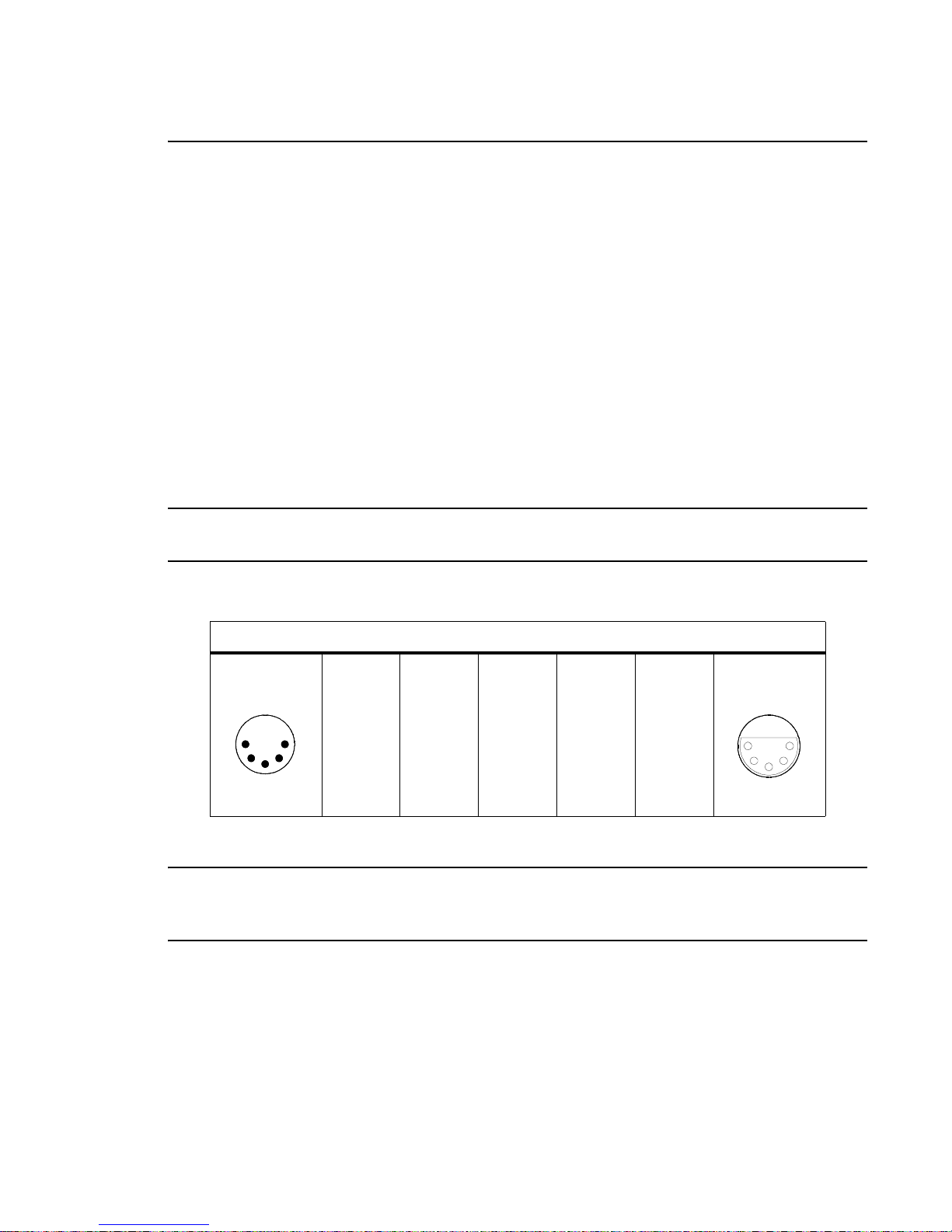
The VL3000 series luminaire is equipped with two, 5-pin XLR connectors for DATA IN and DATA
THRU (out) applications. DATA IN requires a 5-pin, female XLR connector and DATA THRU
requires a 5-pin, male XLR connector. When purchasing or constructing data cables, it is important
that not only the correct cable type be used, but also qual ity cable to ensure a reliable DMX512 syste m.
Your cabling should meet the following USITT DMX specification requirements:
• Suitable for use with EIA485 (RS485) operation at 250k baud.
• Characteristic impedance 85-150 ohms, nominally 120 ohms.
• Low capacitance.
• Two twisted pairs.
• Foil and braid shielded.
• 24 AWG minimum gauge for runs up to 1000 feet (300m).
• 22 AWG minimum gauge for runs up to 1640 feet (500m).
Note: Microphone type cables and other general purpose, two-core audio or signal cables are not
suitable for use with DMX512.
The XLR 5-pin connectors should be wired as follows:
Pin/Wire Code to XLR Connectors
Data Thru
Cable Pinout
1
2
Male Conn
4
3
Pin 1
Foil &
Braided
Shield
5
Pin 2
1st
conductor
of 1st
twisted
pair
Data (-)
Pin 3
2nd
conductor
of 1st
twisted
pair
Data (+)
Pin 4
1st
conductor
of 2nd
twisted
pair
Data (-)
Pin 5
2nd
conductor
of 2nd
twisted
pair
Data (+)
Data In
Cable Pinout
5
4
Female Conn
2
3
1
Note: Refer to the USITT Recommended Practice for DMX512 guide for additional information
regarding DMX512 systems. How to obtain a copy is detailed in “Additional Documentation” on
page 1.
02.9678.0001 A 20-Aug-03 9
Page 28
VARI❋LITE® - VL3000™ SERIES LUMINAIRE USER’S MANUAL
Recommended Cable Types/Manufacturers
These are only a few of th e suitable cable types. Any quality EI A4 85, t wis ted pair, 120 ohm, shielde d
cable will also work.
Table 2-1: Recommended Cable Types
Type Pairs
1215A 2 150 PVC 26 IBM Type 6 Office cable 75
1269A 2 100 PTFE 22 (Solid) High Temp, Plenum cable 200
8102 2 100 PVC 24 UL2919 80
8132 2 120 PVC 28 UL2919 80
8162 2 100 PVC 24 UL2493 60
82729 2 100 PTFE 24 High Temp, Plenum cable 200
88102 2 100 PTFE 24 High Temp, Plenum cable 200
89696 2 100 PTFE 22 High Temp, Plenum cable 200
89729 2 100 PTFE 24 High Temp, Plenum cable 200
89855 2 100 PTFE 22 High Temp, Plenum cable 200
9729 2 100 PVC 24 UL2493 60
9804 2 100 PVC 28 UL2960 60
9829 2 100 PVC 24 UL2919 80
9842 2 120 PVC 24 UL2919 80
PC224P 2 110 Polyure-
PC224T 2 110 PVC 22 UL2464 105
PC226T 3 110 PVC 22 UL2464
ZΩ
∗
Jacket AWG Use Temp (F)
Belden Cables
Proplex Cables
22 Heavy Duty and Portable 105
thane
* Characteristic Impedance
Male Termination Connector
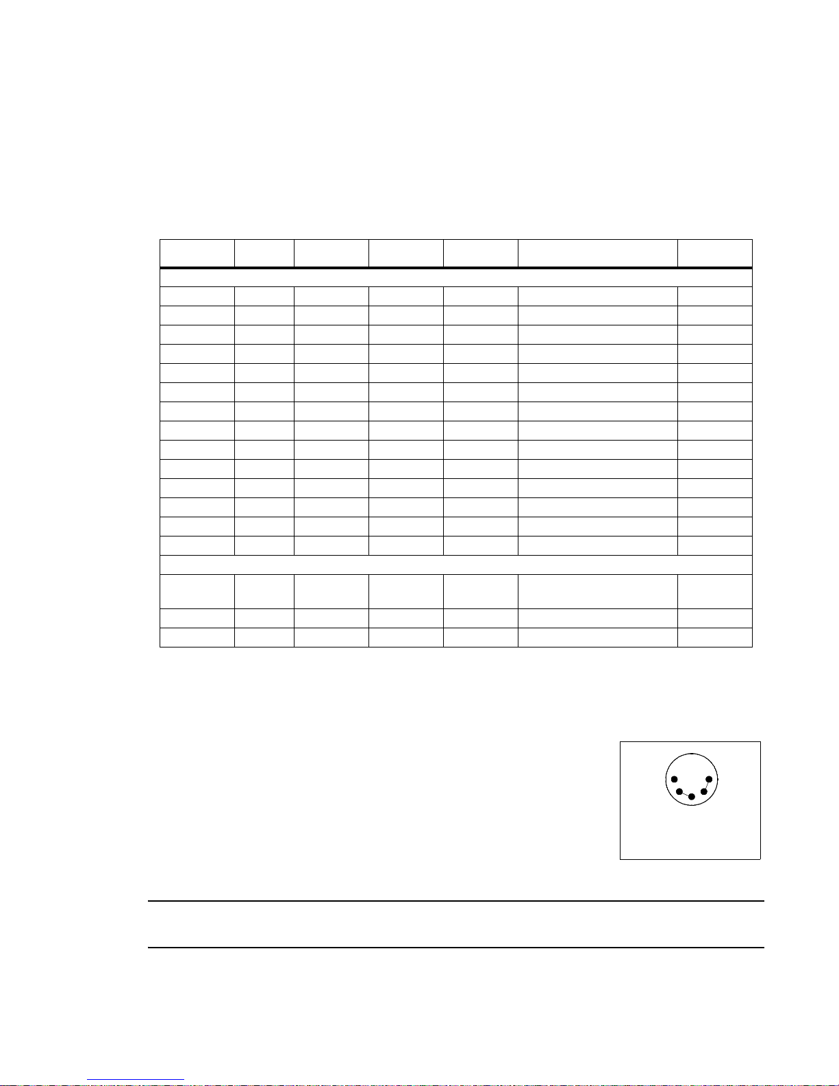
A male XLR termination connector is required at the last luminaire (or
"far end of the li ne" ) to prevent signal reflect ions. Signal reflections may
cancel out the signal at certain line lengths, resulting in errors. The
terminator is also necessary for software downloads and running tests on
multiple luminaires.
To construct your own connector, you will need the
following components:
• 5-pin, male XLR connector.
• Two 1/4W 5% 120 ohm resistors.
Note: A male termination connector is also available as an accessory from Vari-Lite. See
“Replacement Items/Accessories” on page 5.
10 20-Aug-03 02.9678.0001 A
1
2
Solder resistors across
pins 2 & 3, and 4 & 5
5
4
3
Page 29
Installation Procedur es
Hanging the Luminaire
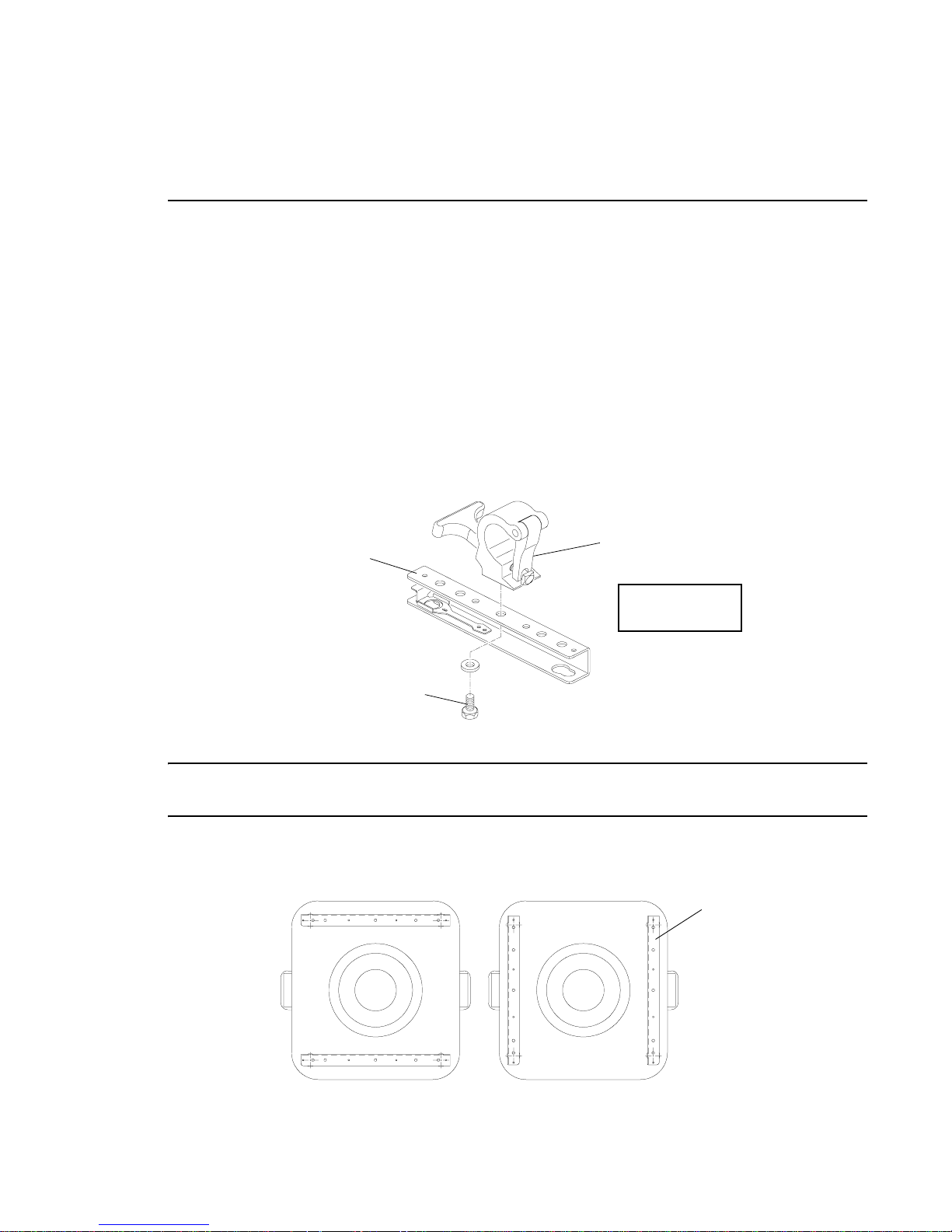
The VL3000 series luminaire can be hung horizontally or vertically from any structure designed to
work with the type of load created by this moving luminaire. Two mounting bracket assemblies
(provided) are used to attach truss hooks or other mounting hardware as required. Many compatible
truss hooks are available from different manufacturers for your particular needs.
A minimum of one hook per truss hook bracket is required. If mounting method does not use truss
hooks, two attac hment points per truss hook bra cke t are required. When attachi ng more than one point
on a single bracket, the attach points must be spaced as far apart as possible using the supplied
mounting holes.
Install mounting hardware and brackets:
Step 1. Install truss hooks on two provided truss hook brackets as required.
Bracket
INSTALLATION : INSTALLATION PROCEDURES
Mega Claw Truss Hook
(not provi ded)
2
Example Truss
Hook Installation
Truss Hook Hardw are
(not provided)
Figure 2-1: Installing Truss Hooks
Note: Various types of truss hooks can be used. The Mega Claw truss hook (as shown in the example
above) as well as many other standard hooks, can be ordered separately.
Step 2. Determine required c onf igu rat i on of bracket installation. Brac ket s ma y be i nst al led in either
orientation as shown.
Bracket
02.9678.0001 A 20-Aug-03 11
Figure 2-2: Bracket Orientation Options
Page 30
VARI❋LITE® - VL3000™ SERIES LUMINAIRE USER’S MANUAL
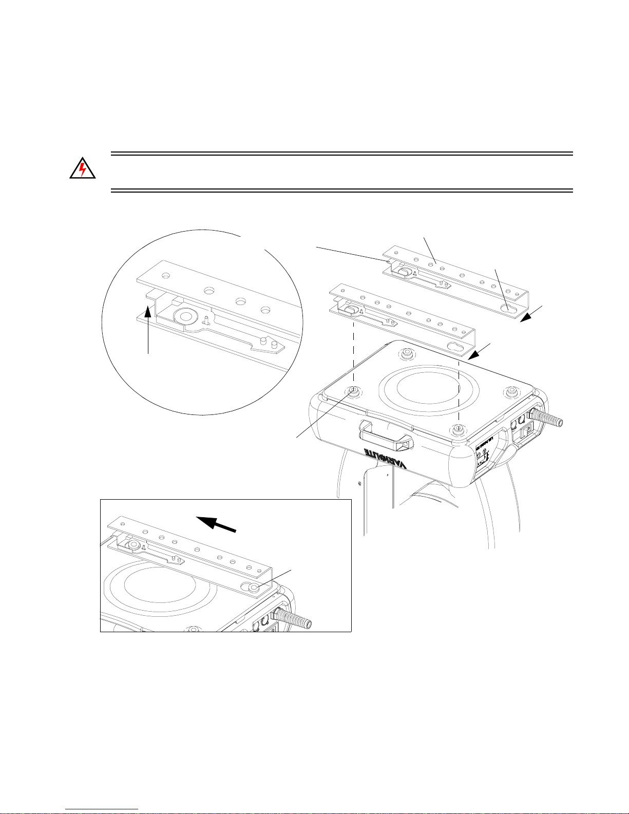
Step 3. While pulling up on locking mechanism release, fit keyed holes onto raised mounting
buttons at bottom of enclosure. Slide forward and release locking mechanism to lock in
place. Ensure brackets are locked securely. (Always face brackets in same direction as
shown.)
WARNING: Ensure that the bracket locking mechanism is fully seated after the bracket is inst alled
on the luminaire.
Locking Mechanism
Press up when
installing or releasing
Truss Hook Bracket
Keyed Hole
Face brackets in
same direction for
all configurations
Raised Mounting Button
Once fitted over buttons,
slide forward to lock
in place
Locked
Figure 2-3: Installing Brackets on Luminaire Enclosure
12 20-Aug-03 02.9678.0001 A
Page 31
INSTALLATION : INSTALLATION PROCEDURES
2
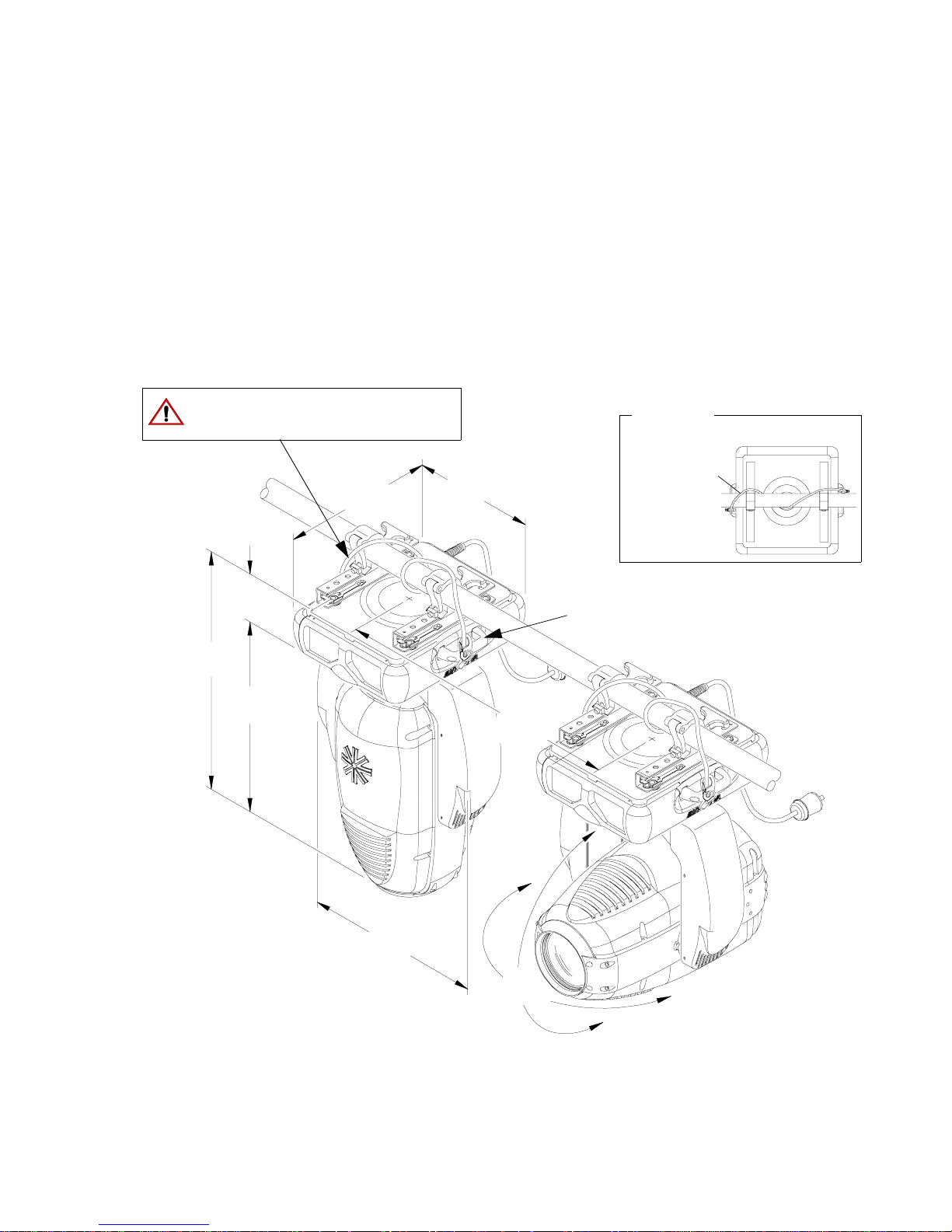
Installing in Truss:
Step 1. Using two people, lift luminaire into mounting position.
Step 2. Secure in place with truss hook. Ensure truss hook hardware that locks hook in place (e.g.
wing bolt) is properly tightened and that luminaire is fully supported.
Step 3. Attach safety cable (as required) as follows:
a. Connect one end of cable to luminaire handle.
b. Loop at least once around truss/pipe and attach other end of cable to other handle.
Step 4. Connect power and data cables according to procedure given in “Connecting Data and
Power” on page 14.
Safety Cable:
Recommended for all hanging installations
and may be required by local codes.
18"
(457 mm)
14.5"
(368 mm)
Top View
Safety Cable
(not included)
Loop at
least once
(127 mm)
31.57"
(802 mm)
(675 mm)
5"
26.56"
20"
(508 mm)
26"
(660 mm)
24"
(610 mm)
Handles are approved
safety cable anchor points.
Figure 2-4: Hanging Configuration and Dimensions
02.9678.0001 A 20-Aug-03 13
Page 32
VARI❋LITE® - VL3000™ SERIES LUMINAIRE USER’S MANUAL
Floor Mounting the Luminaire
The luminaire enclosure is sufficient to stabilize the luminaire in a floor
installation, provided that the mounting surface is flat and sturdy.
Connecting Data and Power
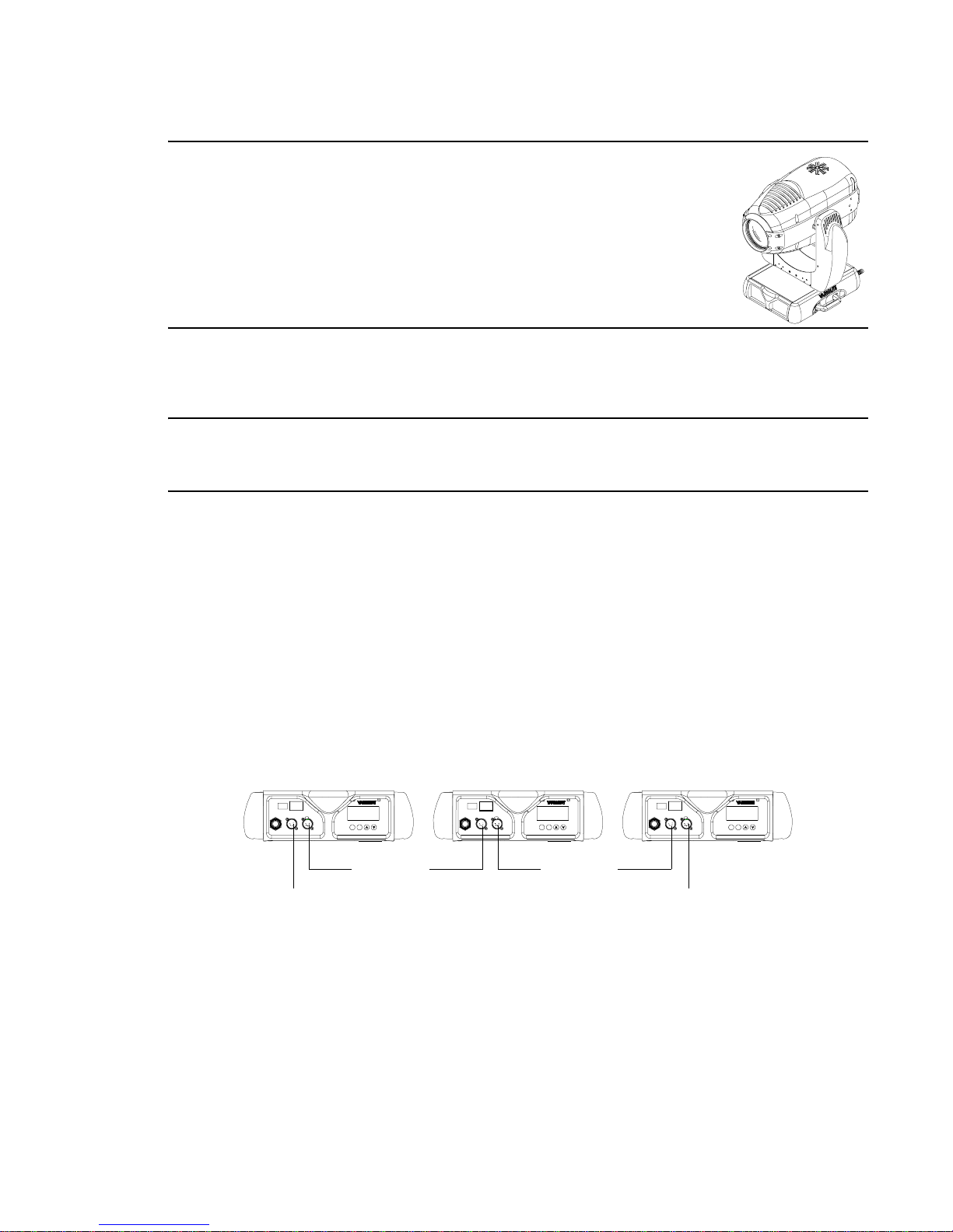
A maximum of 32 luminaires may be connected in any one DMX data link.
Note: This maximum limit applies to the luminaire "daisy chain" only. Your system or console may
require fewer luminaires on a single data link path. Consult your console documentation for more
information.
To connect power and data:
Step 1. Connect data cable from console to first luminaire in chain at DATA IN connector.
Step 2. If required, connect additional data cables from DATA THRU connectors to DATA IN
connectors of remaining luminaires in link.
Step 3. At last luminaire in link, install male termination connector at DATA THRU connector.
(Luminaires and other devices on the same DMX chain may not function properly without
termination.)
Step 4. Connect AC input cable connector to power input source.
Step 5. Dress AC input and data cables and secure them so that they will not interfere with
luminaire head and yoke movement.
AC PWR
~
DATA THRU
DATA IN
AC IN
Data In
(from console)
AC PWR
~
DATA THRU
DATA IN
AC IN
ENTERMENU
ENTERMENU
Data Thru Data Thru
AC PWR
~
DATA THRU
DATA IN
AC IN
ENTERMENU
Termination Connector
Figure 2-5: Connecting Power and Data
14 20-Aug-03 02.9678.0001 A
Page 33

Powering Up
Power Up and Configuration Procedure
Since Lamp On is the default state, the lamp will strike when the luminaire is powered up for the first
time. When AC power is applied, the luminaire will immediately begin a calibration sequence that
steps it through pan and tilt movements. The internal color, gobo, and beam mechanisms will also
move through a full r ange of mot ion. Afte r calibrat ion, the luminaire head wil l either s top at i ts "home"
position (which positions the pan axis at mid-rotation and the head parallel to the yoke with the lens
pointing away from the luminaire upper enclosure) or move to its current DMX-defined position if
DMX data is present. All internal mec hanisms also move to their "home" or DMX-defined positions.
Subsequently, depending on the luminaire’s setting for Lamp Power-Up State (refer to “Menu S ystem
Function Chart” on page 45), when power is applied, the arc lamp will either a) "strike" or ignite -
Lamp On (default), b) await calibration and then stri ke - Cal On, or c) await manu al command to strike
- Lamp Off.
CAUTION: Before applying power, be sure the luminaire is hung or positioned so that the head and
yoke can move freely without restriction.
INSTALLATION : POWERING UP
2
To power up:
• At each luminaire, apply power by switching power switch to "I" (ON) position. Luminaire will
automatically step through following procedure:
a. If Lamp Power-Up State is set to Lamp On, lamp will strike (ignite).
b. Luminaire will cycle through calibration and stop at "home" position.
c. If Lamp Power-Up State is set to Cal On, lamp will strike (ignite) at end of calibration
sequence.
02.9678.0001 A 20-Aug-03 15
Page 34

VARI❋LITE® - VL3000™ SERIES LUMINAIRE USER’S MANUAL
Addressing
Program Starting Address
The address setting for DMX console controlled systems is entered using the Menu Display (refer to
“Menu Operation” on page 42). The luminaire retains the DMX address even if power is removed.
Note: Refer to your console operating instructions for specific information regarding its addressing
requirements.
Program a DMX starting address:
Step 1. Press [Menu].
Step 2. Press [Up] / [Down] arrows until Ad dress appears. Press [Enter].
Step 3. Press [Up] / [Down] arro ws to enter starting addr ess.
Step 4. Press [Enter] to set.
Program Starting Address Without Calibrating
Luminaire
It is possible to bypass the calibration sequence and go directly to the Menu Display programming in
order to pre-program an address setting.
Program starting address without calibrating luminaire:
• While powering up luminaire, press and hold [Menu]. Program address as in Program Starting
Address above.
Note: The luminaire will require a reset to restore control.
16 20-Aug-03 02.9678.0001 A
Page 35

CHAPTER 3.
Operation
This chapter contains instructions for operating the luminaire using DMX control and for
updating the internal software.
• DMX Operation
• DMX Mapping
• Luminaire Timing
• Updating Software
02.9678.0001 A 20-Aug-03 17
Page 36
VARI❋LITE® - VL3000™ SERIES LUMINAIRE USER’S MANUAL
DMX Operation
Channel Mapping
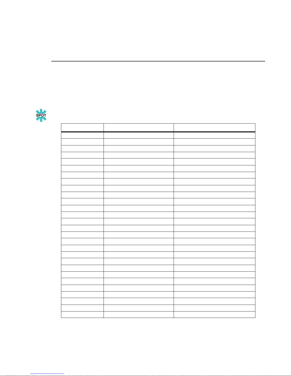
These tables assume a DMX start address of 1. When a different starting address is used, this address
becomes channel 1 functi on and other function s follow in sequence. ( There is onl y one DMX mode fo r
this luminaire, which is Enhanced 16-bit Mode.)
Table 3-1: VL3000 Spot Luminaire Enhanced 16-Bit Mode
DMX Channel Parameter Range
1 Intensity 0-255
2 Hi Byte Pan 0-65535
3 Lo Byte Pan 0-65535
4 Hi Byte Tilt 0-65535
5 Lo Byte Tilt 0-65535
6 Edge 0-255
7 Zoom 0 (small) - 255 (big)
8 CTO Mixer 0 (open) - 255 (diffused)
9 Blue Mixer 0 (open) - 255 (full saturation)
10 Amber Mixer 0 (open) - 255 (full saturation)
11 Magenta Mixer 0 (open) - 255 (full saturation)
12 Color Wheel 0-216 / 217-255 (spins)
13 Gobo Wheel 1 0-216 / 217-255 (spins)
14 Hi Byte Gobo 1 Index/Rot 0-65535
15 Lo Byte Gobo 1 Index/Rot
16 Gobo Wheel 2 0-216 / 217-255 (spins)
17 Hi Byte Gobo 2 Index/Rot 0-65535
18 Lo Byte Gobo 2 Index/Rot
19 Gobo Wheel 3 0-216 / 217-255 (spins)
20 Hi Byte Gobo 3 Index/Rot 0-65535
21 Lo Byte Gobo 3 Index/Rot
22 Beam Iris 0 (small) - 255 (open)
23 Strobe 0 (open) - 255 (max)
24 Focus Time 0-255
25 Color Time 0-255
26 Beam Time 0-255
27 Gobo Time 0-255
28 Control 0-255
18 20-Aug-03 02.9678.0001 A
Page 37

OPERATION : DMX OPERATION
Table 3-2: VL3000 Wash Luminaire Enhanced 16-Bit Mode
DMX Channel Parameter Range
1 Intensity 0-255
2 Hi Byte Pan 0-65535
3 Lo Byte Pan 0-65535
4 Hi Byte Tilt 0-65535
5 Lo Byte Tilt 0-65535
6 Edge 0-255
7 CTO Mixer 0 (open) - 255 (diffused)
8 Blue Mixer 0 (open) - 255 (full saturation)
9 Amber Mixer 0 (open) - 255 (full saturation)
10 Magenta Mixer 0 (open) - 255 (full saturation)
11 Color Wheel 0-216 / 217-255 (spins)
12 Strobe 0 (open) - 255 (max)
13 Focus Time 0-255
14 Color Time 0-255
15 Beam Time 0-255
16 Control 0-255
3
02.9678.0001 A 20-Aug-03 19
Page 38
VARI❋LITE® - VL3000™ SERIES LUMINAIRE USER’S MANUAL
Control Channel Functions
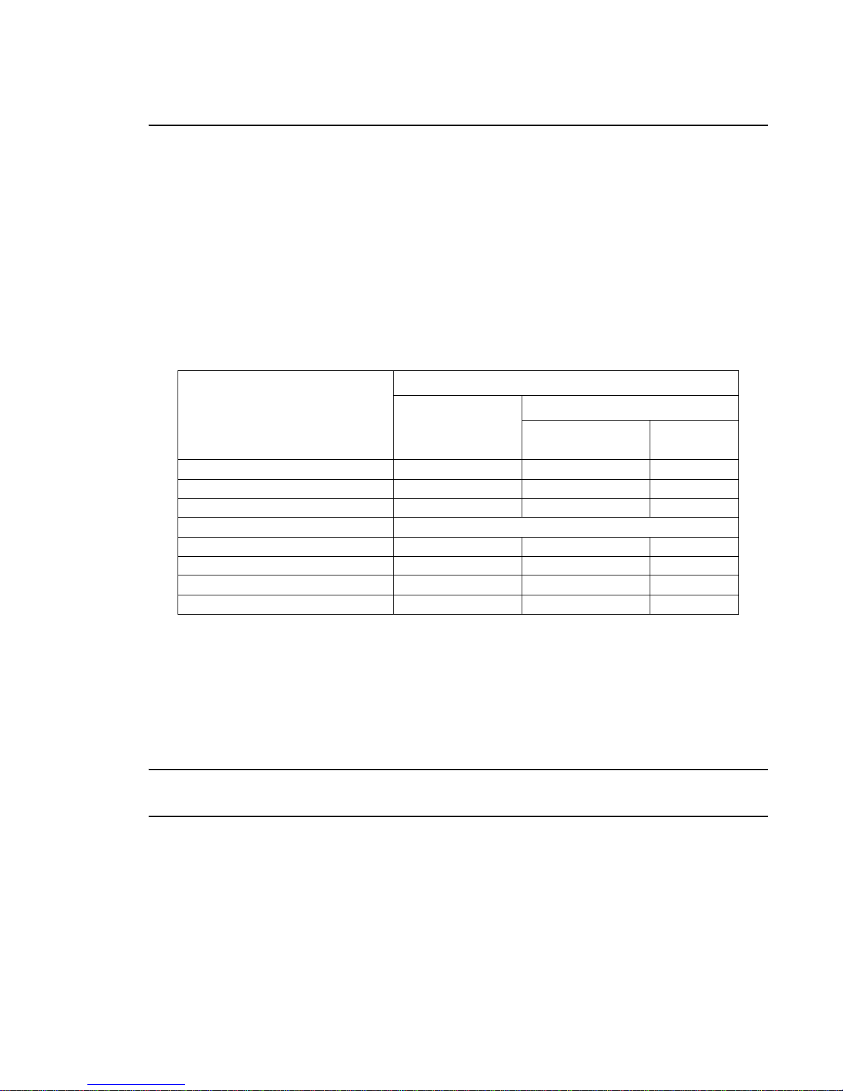
Control channel functions allow special actions such as reset, lamp on/off and partial recalibration.
These must be executed with zero time transition or with timing disabled. Discrete values must be
used; not manual controls such as faders or encoders (see chart below for values).
Reset - resets all lum inaire mechanisms.
Lamp On or Lamp Off - switches lamp on or off.
Partial Recalibration - resets only the target mechanism (color, gobo, zoom, etc.) without affecting
others.
Table 3-3: Control Channel Functions
Control
Channel
Function
Luminaire Reset 32-33 81-87 0
Lamp Off 65-67 165-171 0
Lamp On 98-100 249-255 0
Partial Recalibration of:
- Color 40 100-104 0
- Gobos 45 112-116 0
- Edge/Zoom/Iris 50 126-130 0
- Dimmer/Strobe 55 138-142 0
% Value
Control Channel Value
DMX Value
For 3 Secs
or Greater
After
3 Secs
To use control channel functions:
Step 1. Select an action to be sent.
Step 2. Set control channel value for desired action (for example, 84 for reset). Hold value for 3
seconds.
Step 3. Set control channel value to zero. (This must occur without any scaling values. Action will
be voided if other values are detected between action value and zero.)
Note: A numerical keypad is required for sending values. An encoder or fader does not allow for a
quick value change, which is required to effect the control functions.
20 20-Aug-03 02.9678.0001 A
Page 39
DMX Mapping
Color Control
The luminaire’s color system is composed of a color mixing mechanism and a fixed color wheel. The
follow sections describe these components.
Color Mixing
The color mixing mechanism is made up of four gradu ated color disks : blue, amber , magenta and CT O
(color temperature orang e). These disks pr ovide full-spe ctrum color cro ssfades from paste l to saturated
color.
Table 3-4: DMX Map for Blue, Amber, Magenta and CTO Colors
OPERATION : DMX MAPPING
3
% Value DMX Value Action
00Open
100 255 Full Saturation
Fixed Color Wheel
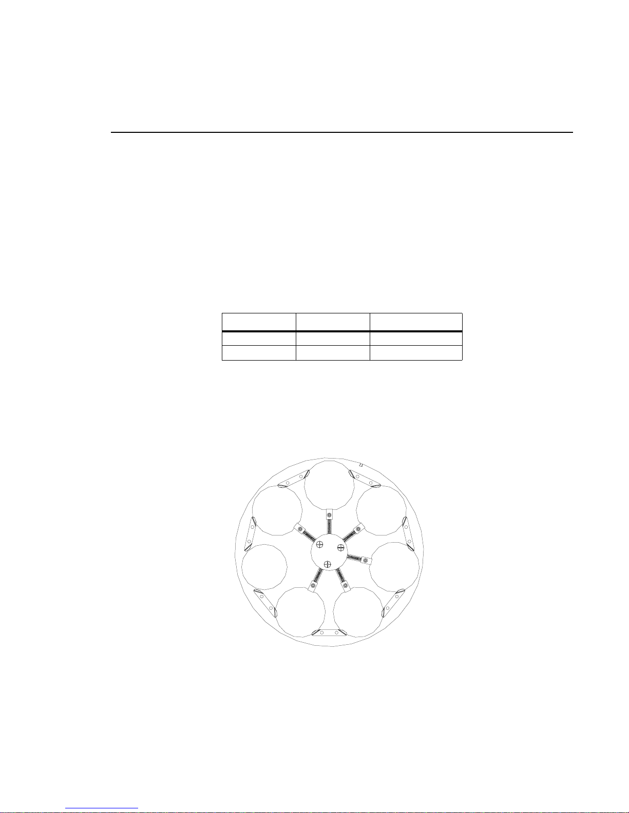
The fixed color wheel offers timed changes, half and full frame positions, and various spin rates in
either direction. The wheel contains seven positions, one being open. The following illustr ati on shows
the standard positions and color configuration:
Pos 2
Orange
Pos 1
Congo
Blue
Open
Pos 6
Deep
Red
Figure 3-1: Fixed Color Wheel Positions
Pos 3
Kelly
Green
Pos 4
Dark
Fuchsia
Pos 5
Magenta
02.9678.0001 A 20-Aug-03 21
Page 40
VARI❋LITE® - VL3000™ SERIES LUMINAIRE USER’S MANUAL
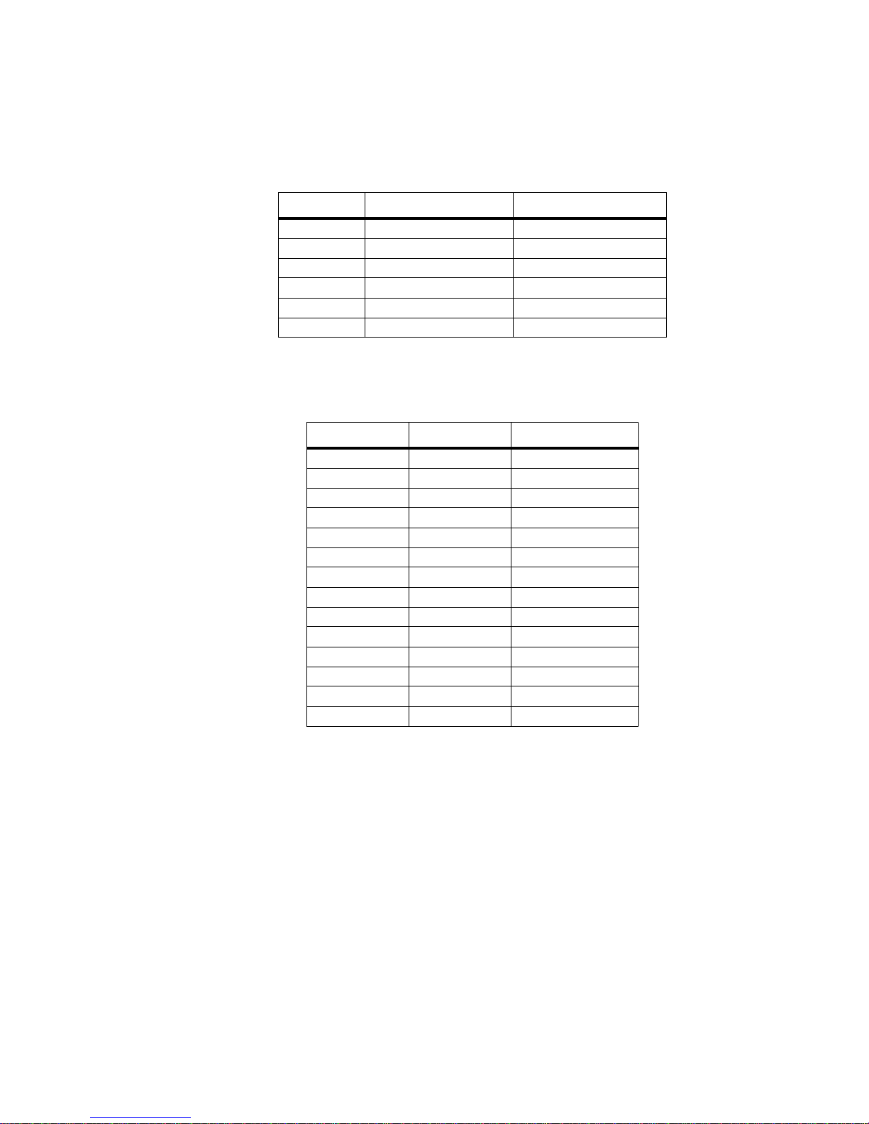
Table 3-5: Color Wheel Standard Configuration Chart
Position Color Filter Part Number
1 Congo Blue 41.9678.0305.03
2 Orange 41.9678.0305.05
3 Kelly Green 41.9678.0305.02
4 Dark Fuchsia 41.9678.0305.06
5 Magenta 41.9678.0305.04
6 Deep Red 41.9678.0305.01
Table 3-6: DMX Map for Fixed Color Wheel
Position DMX Value Action
10Open
1.5 15 Half
231Center
2.5 48 Half
362Center
3.5 77 Half
493Center
4.5 109 Half
5 124 Center
5.5 140 Half
6 155 Center
6.5 171 Half
7 186 Center
7.5 201 Half
22 20-Aug-03 02.9678.0001 A
Page 41
Beam Control
Strobe
OPERATION : DMX MAPPING
3
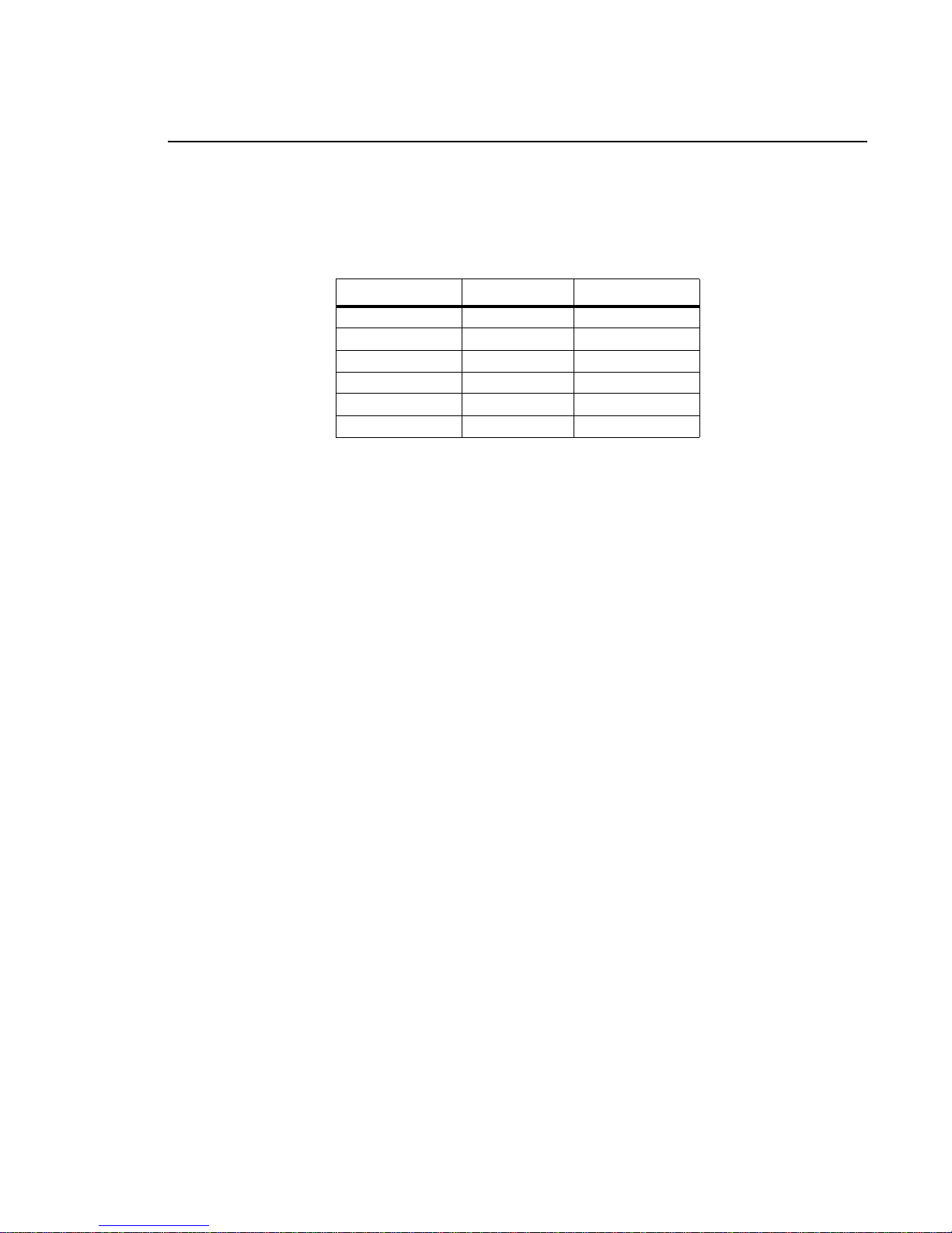
Table 3-7: DMX Map for Strobe
% Value DMX Value Action
00-2Open
1 3-5 Closed
2 6-7 Slow Random
3 8-10 Med Random
4 11-12 Fast Random
5-100 13-255 Speed Range
02.9678.0001 A 20-Aug-03 23
Page 42
VARI❋LITE® - VL3000™ SERIES LUMINAIRE USER’S MANUAL
Gobo/Effects Control
Gobo Wheels 1 and 2
These wheels have six positions, one being open. The following illustration shows the standard gobo
configurations:
POS 1
POS 6
POS 5
POS 4
POS 2
POS 3
Figure 3-2: Gobo Wheels 1 and 2 Positions
Table 3-8: Gobo Wheel 1 Standard Configuration Chart
Position Gobo Style Part Number
1 open n/a
2 Alpha Rays 41.6030.7029
3 Night Sky 41.6030.5011
4 Tribal Break-up 41.6030.5523
5 Pebbles 41.6030.7002
6 Glacier Gag 41.6030.8503
Table 3-9: Gobo Wheel 2 Standard Configuration Chart
24 20-Aug-03 02.9678.0001 A
Position Gobo Style Part Number
1 open n/a
2 Palm Leaves 41.6030.5503
3 Shock Break-up 41.6030.7018
4 Uneven Bars 41.6030. 4211
5 Ice Blocks Gag 41.6030.8509
6 Droplets Gag 41.6030.8506
Page 43
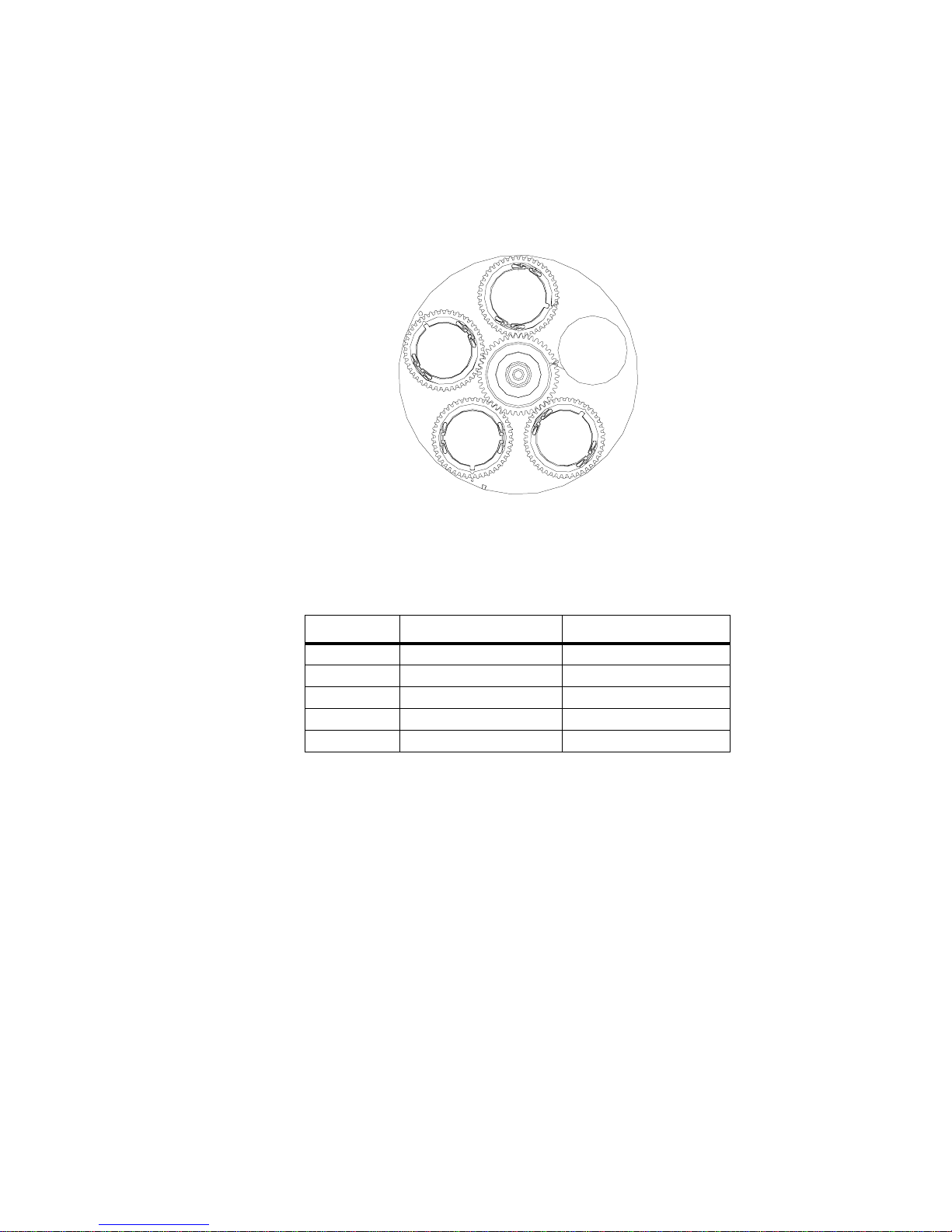
OPERATION : DMX MAPPING
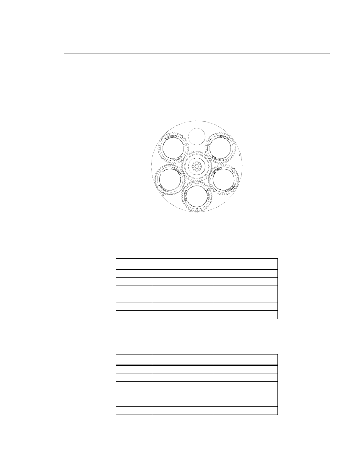
Gobo Wheel 3
This wheel has five positions, one being open. The following illustration shows the standard gobo
configurations:
POS 5
3
POS 4
POS 3
POS 1
POS 2
Figure 3-3: Gobo Wheel 3 Positions
Table 3-10: Gobo Wheel 3 Standard Configuration Chart
Position Gobo Style Part Number
1 open n/a
2 3-Side Prism 41.6030.8003
3 Color Gobo 41.6030.8801
4 Triangle Break-up 41.6030.7024
5 Circle of Ovals 41.6030.6011
02.9678.0001 A 20-Aug-03 25
Page 44
VARI❋LITE® - VL3000™ SERIES LUMINAIRE USER’S MANUAL
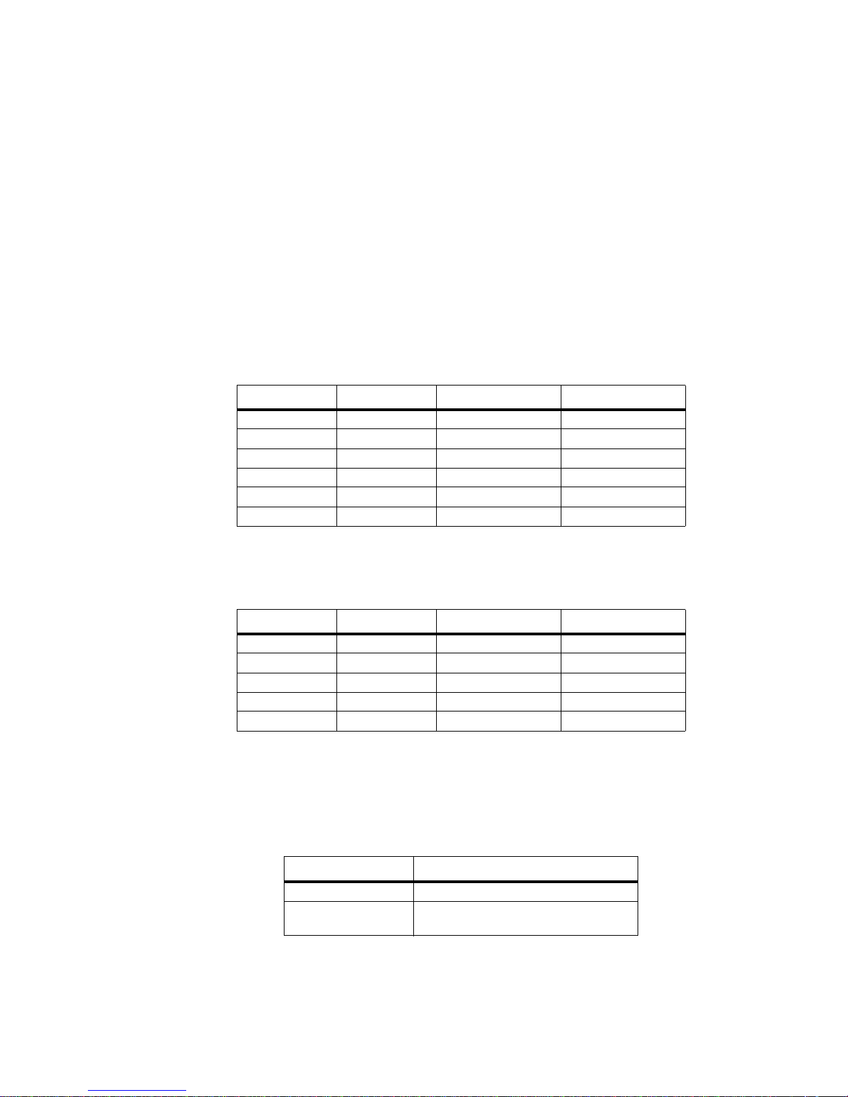
Index/Rotation
The gobo wheels operate in t wo modes: INDEX Mode a nd ROTA TE Mode. The co rresp onding va lues
are given in the DMX Map Tables below. Gobos will also behave as follows:
• Gobo wheels will only stop at whole images.
• It is not necessary for the wheel to complete a full revolution to change a gobo from indexing
mode to rotating mode.
• Timed moves are only available using the Gobo Time channel (27).
• Spins are variable from DMX 217-236 for CCW fast to slow, and 237-255 for CW slow to fast.
Table 3-11: DMX Map for Gobo Wheels 1 and 2
Position Indexing Rotating Function
1 0-7 100-116 Open
2 8-25 117-134 Gobo 1
3 26-44 135-153 Gobo 2
4 45-63 154-172 Gobo 3
5 64-82 173-191 Gobo 4
6 83-99 192-209 Gobo 5
Table 3-12: DMX Map for Gobo Wheel 3
Position Indexing Rotating Function
1 0-10 98-119 Open
2 11-33 120-141 Gobo 1
3 34-54 142-163 Gobo 2
4 55-75 164-184 Gobo 3
5 76-97 185-206 Gobo 4
The Gobo Index function utilizes 16-bit control which offers enhanced resolution whether in INDEX
or ROTATE mode.
Table 3-13: Index/Rotation Range
Function Range
Index 0-65535
Rotate 0 (cw max) - 32599 (cw min)
32600-33047 (stop)
26 20-Aug-03 02.9678.0001 A
Page 45
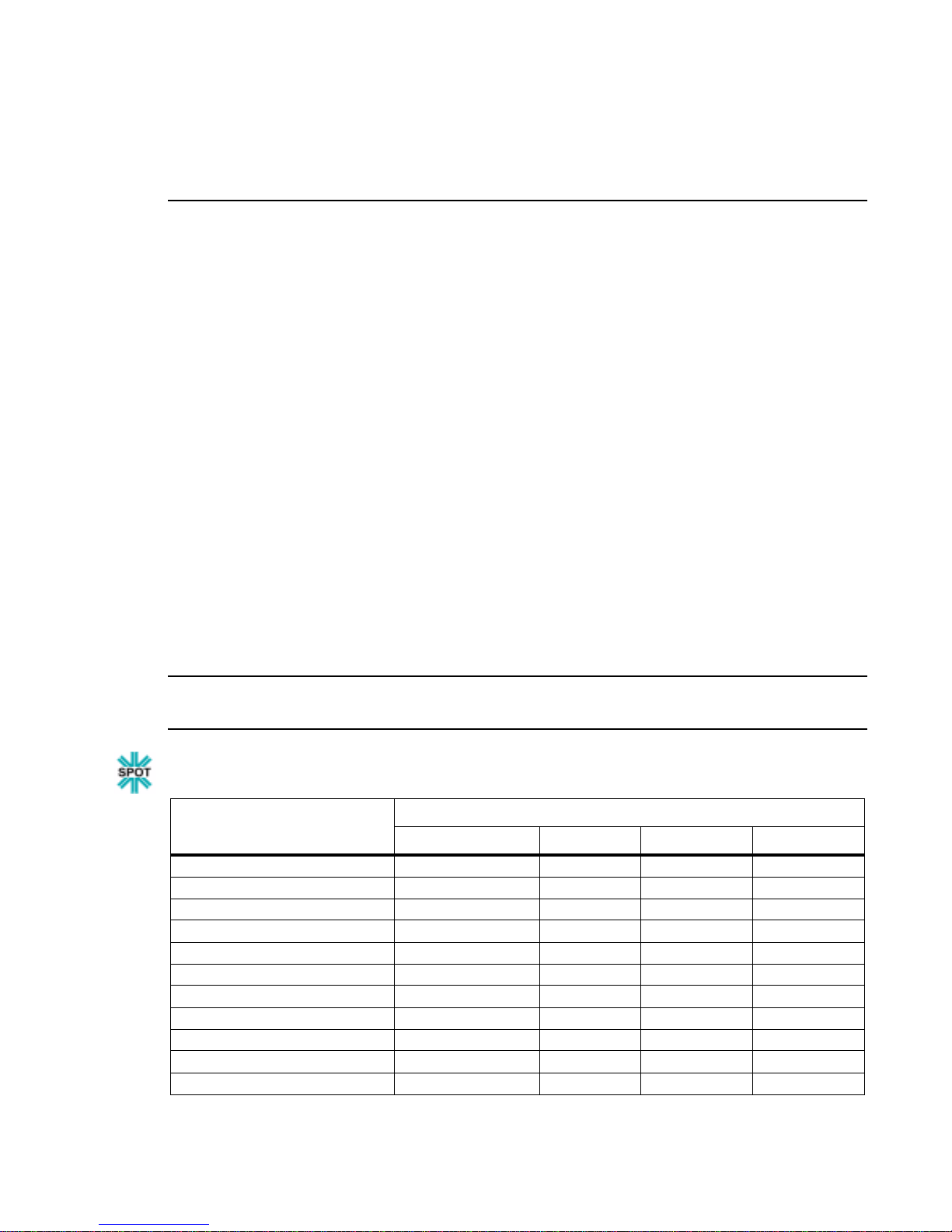
Luminaire Timing
Timing Channel Infor mation
Timing channel control improves the timed moves of certain groups of parameters. We provide up to
four timing channels, one for focus (Pan and Tilt), one for color paramet er s, one for bea m para mete rs,
and one for gobo wheel position (spot version only).
Types of timing control:
• Timing Control Channel: the luminaire uses its timing channel value to calculate a smooth
continuous movement for a given time and transition.
• Console Timing: the console calculates the time duration between the DMX increments to be sent
for a given time and transition.
Guidelines:
• Timing channels support time values of up to six minutes.
• To use a timing channel instead of console timing, it is necessary to set the timing channel to the
desired value and set cue and/or parameter time to zero. A combination of time controls can
produce unexpected results.
OPERATION : LUMINAIRE TIMING
3
• The default value setting in the profile should be 255 (proportional control) to allow smooth
movement when using console timing.
• The timing channel data should change as a snap. A zero value will give the fastest move,
however, without any smoothing this can appear "steppy" in console timed moves.
Note: Some parameters have been excluded from the timing channels. Wheel spin and gobo rotation
rate changes are not affected by timing channels.
Table 3-14:
Pan (Hi Byte/Lo Byte)
Gobo Wheels 1, 2 and 3
VL3000 Spot Luminaire Channel Function / Timing Channel Relationship
Timing Channel
Channel Function
Focus Time Color Time Beam Time Gobo Time
Tilt (Hi Byte/Lo Byte)
Blue
Amber
Magenta
CTO
Color Wheel
Zoom
Edge
Beam Iris
02.9678.0001 A 20-Aug-03 27
Page 46
VARI❋LITE® - VL3000™ SERIES LUMINAIRE USER’S MANUAL
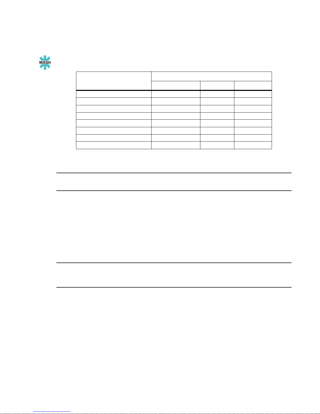
Table 3-15:
VL3000 Wash Luminaire Channel Function / Timing Channel Relationship
Timing Channel
Channel Function
Focus Time Color Time Beam Time
Pan (Hi Byte/Lo Byte)
Tilt (Hi Byte/Lo Byte)
Blue
Amber
Magenta
CTO
Color Wheel
Beam Spreader
A timing value of zero is full speed. A time value of 100% (or 255 in DMX) enables the associated
parameter(s) to follow cue fade time (console time) rather than the timing channel.
Note: The particular storing syntax f or your cons ole, as well as in struc tions on how to wr ite pa rt cue s,
can be found in the operation manual for that console.
To use these channels, you must:
Step 1. Create the cue, including color, gobo, edge and diffusion as required.
Step 2. Decide which fixtures and which parameter groups will use timing channels.
Step 3. Assign a value to the particular timing channel(s) you wish to use (for timing information,
see chart on next page).
Step 4. Set console timing (or cue fade time) for parameters and timing channels to zero seconds.
Step 5. Store cue.
Note: Avoid changing timing channel values in a fading cue. This can cause unexpected behavior in
the luminaire as the timing channel value is updated over time. Timing channel values and the final
destination of the parameters affected by the timing channel should always be sent in a zero count.
28 20-Aug-03 02.9678.0001 A
Page 47

OPERATION : LUMINAIRE TIMING
Timing channels can be set in either % or 0-255 (DMX) modes, with the following values assigned:
3
Table 3-16:
% Value DMX = Seconds
130.6
251
381.6
4102
5132.6
6153
7183.6
8204
9234.6
10 25 5
11 28 5.6
12 31 6.2
13 33 6.6
14 36 7.2
15 38 7.6
Timing Channels Map
0 Full Speed
10.2
20.4
40.8
61.2
71.4
91.8
11 2.2
12 2.4
14 2.8
16 3.2
17 3.4
19 3.8
21 4.2
22 4.4
24 4.8
26 5.2
27 5.4
29 5.8
30 6
32 6.4
34 6.8
35 7.0
37 7.4
02.9678.0001 A 20-Aug-03 29
Page 48

VARI❋LITE® - VL3000™ SERIES LUMINAIRE USER’S MANUAL
Table 3-16: Timing Channels Map (Continued)
% Value DMX = Seconds
39 7.8
40 8
16 41 8.2
42 8.4
17 43 8.6
44 8.8
45 9
18 46 9.2
47 9.4
19 48 9.6
49 9.8
50 10
20 51 10.2
52 10.4
53 10.6
21 54 11
55 11
22 56 12
57 12
58 13
23 59 13
60 14
24 61 14
62 14
63 15
25 64 15
65 16
26 66 16
67 16
68 17
27 69 17
70 18
28 71 18
72 18
73 19
29 74 19
75 20
30 76 20
77 20
78 21
31 79 21
80 21
30 20-Aug-03 02.9678.0001 A
Page 49

OPERATION : LUMINAIRE TIMING
Table 3-16: Timing Channels Map (Continued)
% Value DMX = Seconds
81 22
32 82 22
83 23
33 84 23
85 23
86 24
34 87 24
88 25
35 89 25
90 25
91 26
36 92 26
93 27
37 94 27
95 27
96 28
38 97 28
98 29
39 99 29
100 29
101 30
40 102 30
103 30
104 31
41 105 31
106 32
42 107 32
108 32
109 33
43 110 33
111 34
44 112 34
113 34
114 35
45 115 35
116 36
46 117 36
118 36
119 37
47 120 37
121 38
48 122 38
3
02.9678.0001 A 20-Aug-03 31
Page 50

VARI❋LITE® - VL3000™ SERIES LUMINAIRE USER’S MANUAL
Table 3-16: Timing Channels Map (Continued)
% Value DMX = Seconds
123 38
124 39
49 125 39
126 39
127 40
50 128 40
129 41
51 130 41
131 41
132 42
52 133 42
134 43
53 135 43
136 43
137 44
54 138 44
139 45
55 140 45
141 45
142 46
56 143 46
144 47
57 145 47
146 47
147 48
58 148 48
149 49
59 150 49
151 49
152 50
60 153 50
154 50
155 51
61 156 51
157 52
62 158 52
159 52
160 53
63 161 53
162 54
64 163 54
164 54
32 20-Aug-03 02.9678.0001 A
Page 51

OPERATION : LUMINAIRE TIMING
Table 3-16: Timing Channels Map (Continued)
% Value DMX = Seconds
165 55
65 166 55
167 56
66 168 56
169 56
170 57
67 171 57
172 58
68 173 58
174 58
175 59
69 176 59
177 59
178 60
70 179 60
180 65
71 181 65
182 65
183 70
72 184 70
185 75
73 186 75
187 75
188 80
74 189 80
190 85
75 191 85
192 85
193 90
76 194 90
195 95
77 196 95
197 95
198 100
78 199 100
200 110
79 201 110
202 110
203 120
80 204 120
205 120
81 206 130
3
02.9678.0001 A 20-Aug-03 33
Page 52

VARI❋LITE® - VL3000™ SERIES LUMINAIRE USER’S MANUAL
Table 3-16: Timing Channels Map (Continued)
% Value DMX = Seconds
207 130
208 140
82 209 140
210 140
211 150
83 212 150
213 160
84 214 160
215 160
216 170
85 217 170
218 180
86 219 180
220 180
221 190
87 222 190
223 200
88 224 200
225 200
226 210
89 227 210
228 210
229 220
90 230 220
231 230
91 232 230
233 230
234 240
92 235 240
236 250
93 237 250
238 250
239 260
94 240 260
241 270
95 242 270
243 270
244 280
96 245 280
246 290
97 247 290
248 290
34 20-Aug-03 02.9678.0001 A
Page 53

OPERATION : LUMINAIRE TIMING
Table 3-16: Timing Channels Map (Continued)
% Value DMX = Seconds
249 300
98 250 300
251 310
99 252 310
253 310
254 310
100 255 Follows Cue Data
3
02.9678.0001 A 20-Aug-03 35
Page 54

VARI❋LITE® - VL3000™ SERIES LUMINAIRE USER’S MANUAL
Updating Software
Reprogramming Luminaires
In some cases, it may be desir able t o upgr ade th e lumina ire’s operating software. This process re quires
a PC, VLDownload.exe, .bin files and the Luminaire Programming Kit (28.9661.0054).
Components Overview
Computer Requirements
• PC running Windows 95/98, Windows NT (4.0 or higher), or Windows 2000. (Program is not
compatible with Macintosh computers.)
• Serial communication port. (RS-232 only, USB not supported.)
VL Download Program
The VL Download.exe program allows you to transfer new versions of the operating software (.bin
files) to the luminaires via the PC. The VL Download.exe and current .bin files are available from the
Product Downloads page at www.vari-lite.com. Instructions for installing the program on your PC are
also available on the Product Downloads page.
Luminaire Programming Kit
The luminaire programming kit allows you to connect your PC to the luminaire chain in order to
update software.
Luminaire Programming Kit (28.9661.0054) components:
• 6-Ft. Serial Straight Thru DB9M-F Cable (46.6033.0006)
• RS-232 to RS-485 Interface Converter (46. 6036.0001)
• 6-Ft. RJ45 to 5-Pin Female XLR Cable (25.9661.0055)
36 20-Aug-03 02.9678.0001 A
Page 55
OPERATION : UPDATING SOFTWARE
3
Reprogramming Procedure
Note: Up to 32 luminaires can be programmed at the same time if they are data li nke d t oget her. Refer
to “Connecting Data and Power” on page 14. (Programming more than 32 luminaires will require
programming in batches of 32 or less.)
To update luminaire software:
Step 1. From Product Downloads page at www.vari-lite.com, download and install the
VLDownload.exe program and requi red .bin fi les onto you r PC (followi ng instruc tions at the
website).
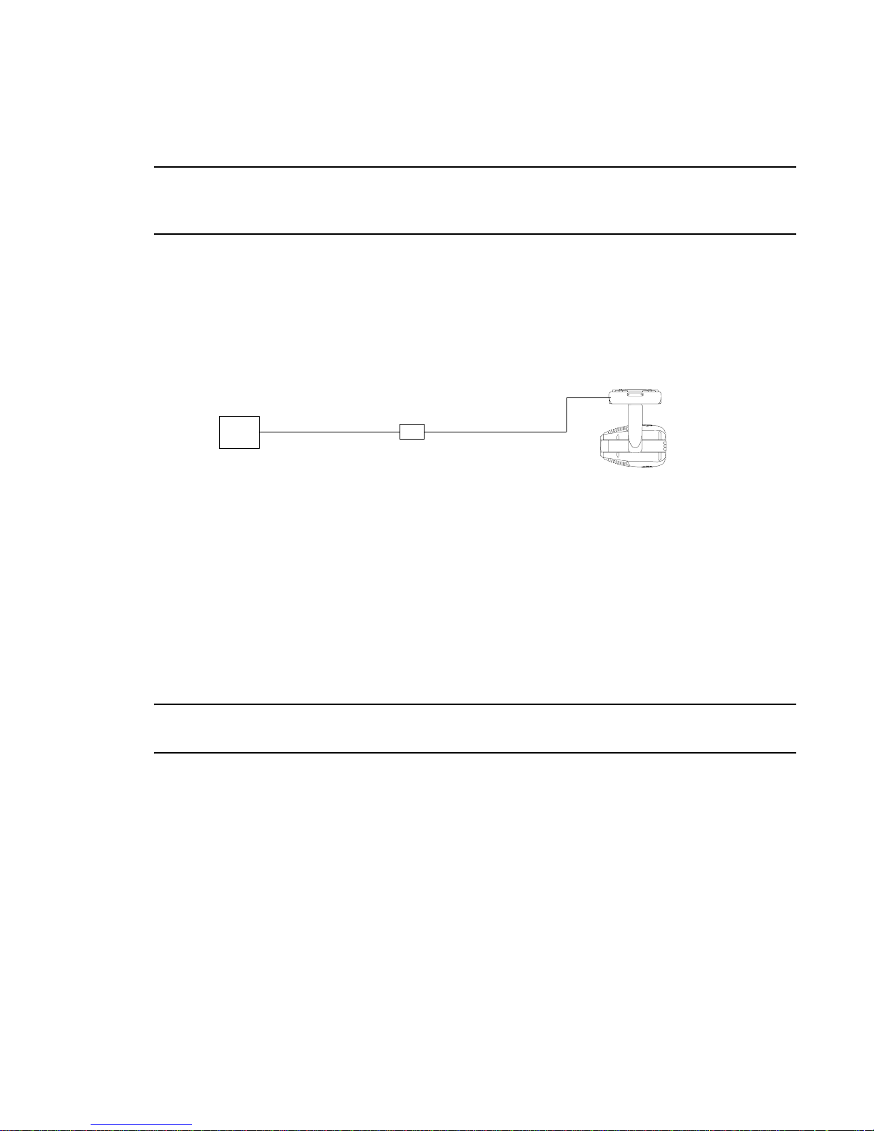
Step 2. Assemble Luminaire Programming Kit components by connecting Serial Straight Thru
Cable and RJ45-to-XLR cable to Interface Converter.
Serial Straight
Thru Cable RJ45-to-XLR Cable
PC
Interface
Converter
Figure 3-4: Hardware Setup
Step 3. Connect Serial Straight Thru cable to serial Comm Port of PC and connect RJ45-to-XLR
cable to DMX In connector of luminaire.
Step 4. Apply pow er to PC and luminaire( s).
Step 5. Run VLDownload.exe program by selecting from Start menu Programs list or by selecting
from C:\ProgramFiles\Vari-Lite\VLDownload Program directory. (Luminaire Software
Download window will open.)
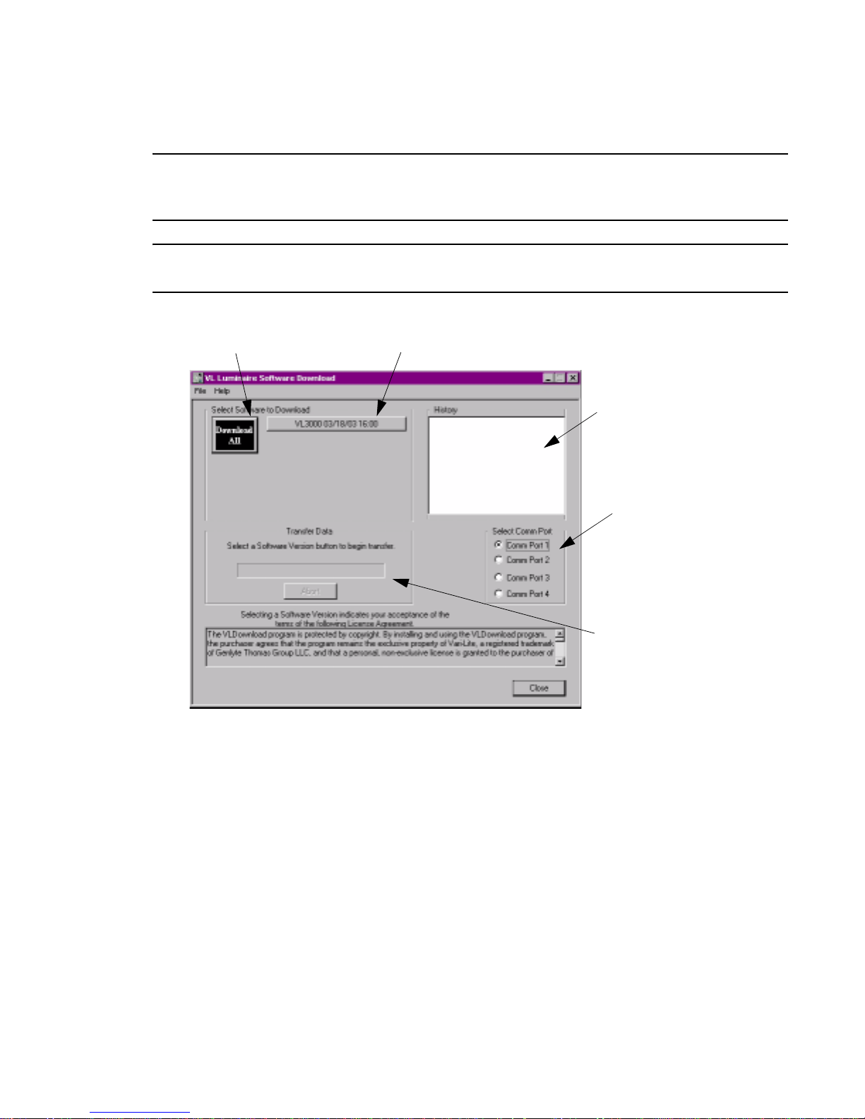
Step 6. At Select Comm Port section of window (refer to Figure 3-5 on next page), select serial
Comm Port (Comm Port 1, Comm Port 2, Comm Port 3, or Comm Port 4) where Serial
Straight Thru Cable is connected.
Note: DMX Data must be disconnected before downloading software to luminaires. (Do not merge
with DMX signal.)
Step 7. At Select S oftware to Download section of window, select required luminaire
software version to download by clicking its button or select Download All. (Software
version is identified by the date and time: MM/DD/YY and HH:MM.) The buttons function
as follows:
Luminaire
(DMX In)
VL3000 button downloads the software to all VL3000 luminaires.
Download All button is the equivalent of executing all of the specific software version
buttons shown in the window (if appli cable). They will be exe cuted one at a time in the order
they appear in the window. This button can be used when any combination of VARI❋LITE
luminaires are connected to the PC.
Step 8. Download will proceed. Once download is complete, luminaire will automatically
recalibrate. Once recalibration is complete, luminaire is ready for operation with its new
software version.
02.9678.0001 A 20-Aug-03 37
Page 56
VARI❋LITE® - VL3000™ SERIES LUMINAIRE USER’S MANUAL
Step 9. Click Close to exit.
Note: The History section of the window shows what specific types of luminaire software have been
downloaded since the beginning of the session (window will reset once the program is closed and reopened).
Note: V ers ion dates s hown in this gr aphic are for illus tration purposes onl y and may not cor respond to
the version you are downloading.
Click to download all
listed softwa re versio ns
to connected luminaire(s)
Click to download specific software
version to connected luminaire(s)
Lists the specific versions
of software that have been
downloaded
Select PC serial
port where cable
is connected.
Will show current
progress of download
Figure 3-5: VL Download Program Window
Verify software version at luminaire:
Step 1. At Menu Display, press [Menu].
Step 2. Press [Up] / [Down] arrows until Fixture appears. Press [Enter].
Step 3. Press [Up] / [Down] arrows until Version appears. Press [Ente r ].
The first half of the version will be displayed as a date (MM.DD.YY). For example,
03.18.03 (March 18, 2003).
Press [Up] / [Down] arrows to display second half of version. This will be displayed as a
time (HH:MM). For example, 16:00
38 20-Aug-03 02.9678.0001 A
Page 57
OPERATION : UPDATING SOFTWARE
3
Transferring Software From Luminaire to Luminaire
It is possible t o tra nsfer speci fic software versi ons be twe en luminai res. As in t he cas e of ins tallin g new
software versions, multiple luminaires can be programmed at the same time if they are data linked
together (r efer to “Connecting Data and Power” on page 14), however a maximum of 32 luminaires
can be updated at once.
Hardware Requirements
Data cables used in this process must have two twisted pairs and a shield. It is also recommended that
cables meet all other USITT DMX specification requirements. Refer to “Data Cables” on page 9.
A termination connector is used in this process. Refer to page 10 for more information regardi ng the
construction of this connector.
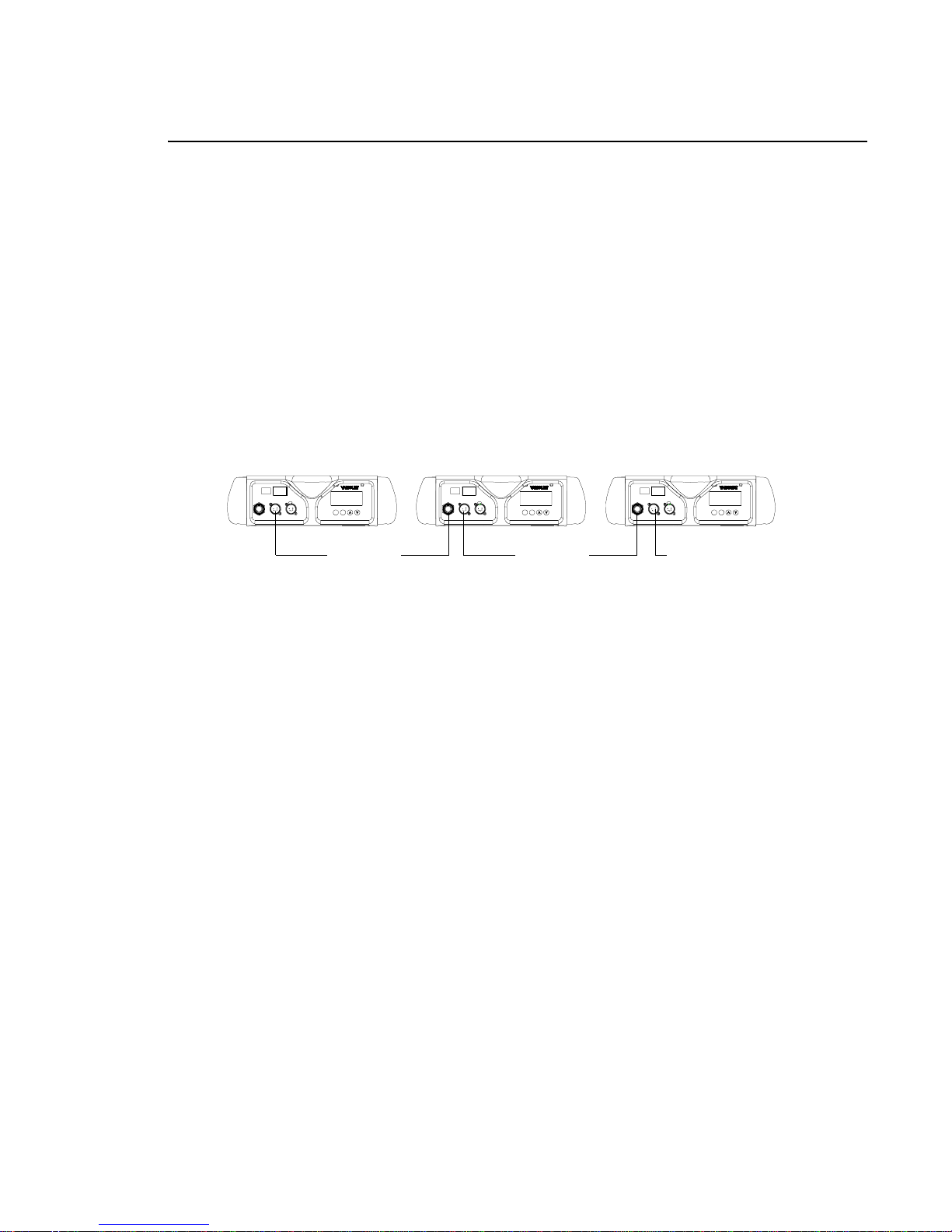
Master luminaire containing
software version to download
AC PWR
DATA THRU
DATA IN~
AC IN
ENTERMENU
Data Thru
Luminaire 1
requiring update
AC PWR
DATA THRU
DATA IN~
AC IN
Data Thru
Luminaire 2
requiring update
AC PWR
DATA THRU
DATA IN~
AC IN
ENTERMENU
ENTERMENU
Termination Connector
Figure 3-6: Software Transfer Setup
Transfer Procedure
This procedure is used to transfer software versions between luminaires.
Step 1. At last luminaire, install male termination connector into DATA THRU XLR connector.
Step 2. At master luminaire (first in chain) Menu Display, press [Menu].
Step 3. Press [Up] / [Down] arrows until Fixture appears.
Step 4. Press [Up] / [Down] arrows until Do wnload appears. Press [Enter].
Step 5. OK? will be displayed. Press [Enter] to accept.
Step 6. Download will proceed. ( Downl oad will take 4-5 seconds.) Th e number of blocks displayed
will be less in a luminair e-to-luminaire download than in a PC- to-luminair e download for
the same software version.
Step 7. Once download is complete, luminaire will automatically recalibrate. Once recalibration is
complete, luminaire is ready for operation with its new software version.
02.9678.0001 A 20-Aug-03 39
Page 58

VARI❋LITE® - VL3000™ SERIES LUMINAIRE USER’S MANUAL
Verify software version at luminaire:
Step 1. At Menu Display, press [Menu].
Step 2. Press [Up] / [Down] arrows until Fixture appears. Press [Enter].
Step 3. Press [Up] / [Down] arrows until Version appears. Press [Ente r ].
The first half of the version will be displayed as a date (MM.DD.YY). For example,
03.18.03 (March 18, 2003).
Press [Up] / [Down] arrows to display second half of version. This will be displayed as a
time (HH:MM). For example, 16:00
40 20-Aug-03 02.9678.0001 A
Page 59

CHAPTER 4.
Menu System
This chapter contains instructions for operating the luminaire using the Menu Display feature.
• Menu Operation
• Menu Functions
• Self-Tests
02.9678.0001 A 20-Aug-03 41
Page 60
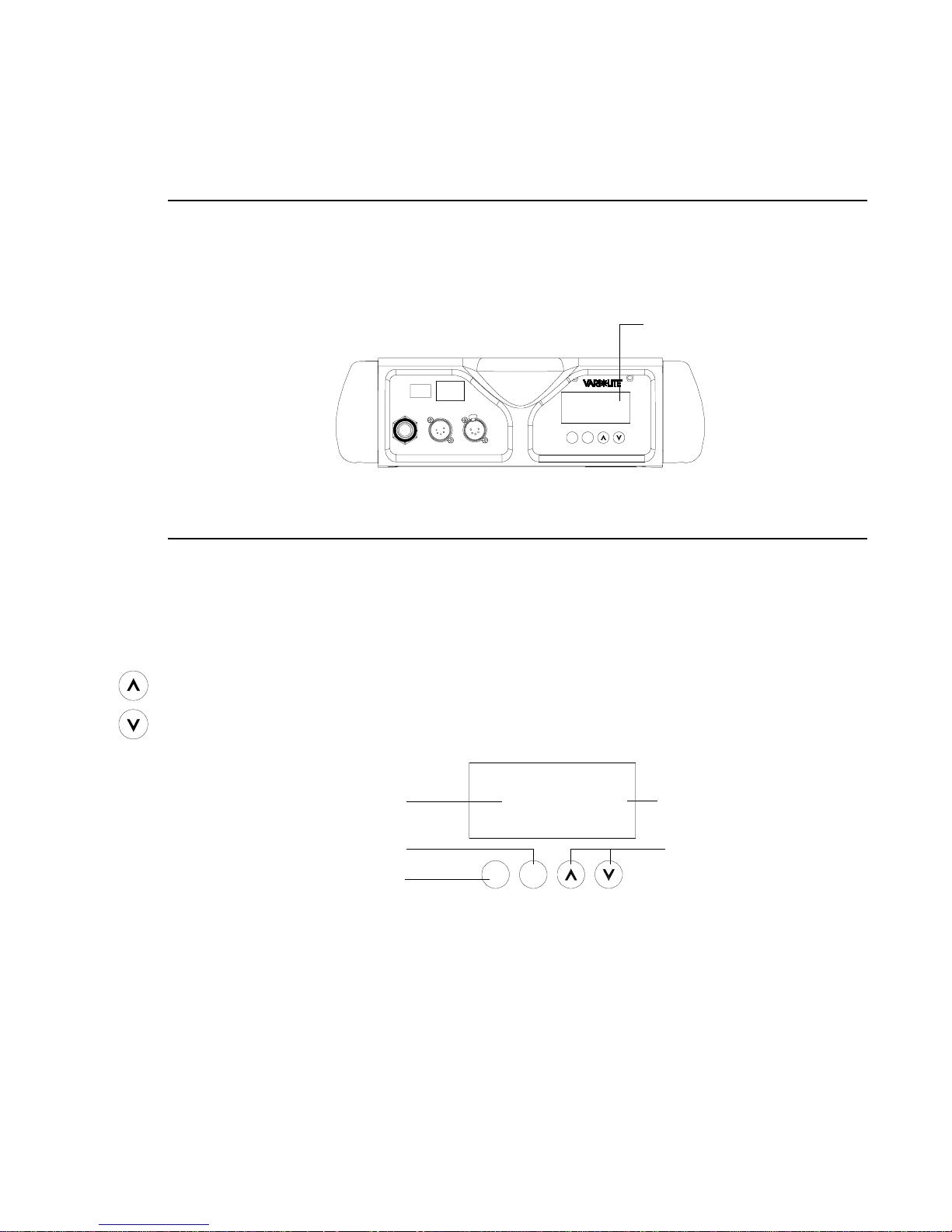
VARI❋LITE® - VL3000™ SERIES LUMINAIRE USER’S MANUAL
R
Menu Operation
What Is the Menu System?
The menu system is a programmable set of commands used to confi gure, add ress, ope rate, and test the
luminaire. The menu system is controlled at the Menu Display available at the enclosure input panel.
AC PWR
Menu Display
AC IN
~
DATA IN
DATA THRU
ENTERMENU
Figure 4-1: Menu Display Location
Controls Operation
The menu system is controlled by four buttons. These buttons function as follows:
[Menu] button. Displays the menu, or if at first level, the current address.
[Enter] button. Selects the current menu option or stores current data value.
[Up] arrow. Scrolls menu options upward or increases current data value.*
[Down] arrow. Scrolls menu options downward or decreases current data value.*
Menu function or value
Selects the current menu op ti on
or enters current data value
Displays the menu, or if at
first level, the current address
Address
ENTE
MENU
Backlit LCD Display
Changes a value or
scrolls through menus *
* The arrows will have opposite fu nctions i f the luminai re is hun g upsi de down in a hang ing o rientati on
due to the automatic orientation feature. In other words, the arrow pointing downward always functions as down/decrease and the arrow pointing upward always functions as up /in creas e regard l ess of
the luminaire orientation.
42 20-Aug-03 02.9678.0001 A
Page 61

MENU SYSTEM : MENU OPERATION
4
To enter the menu system, first press [Menu]. The functions displayed will be 1st level functions.
Scroll through the 1st level functions by pressing [Up] / [Down] arrows. Once the desired function
appears in the display, press [Enter]. You are now at the 2nd level. Once again, press the [Up] /
[Down] arrows to scroll through 2nd level fu nct ions. Press [Enter] to acce ss 3rd level functions and so
forth. When the hi ghe st level for the functio n i s rea ched, [Up] / [Down] arrows can be pressed to enter
a value or select a toggle activation such as On/Off. Press [Enter] to store the value or select an action.
For example:
1st Level
Test All @1 RUN TEST
2nd Level 3rd Level
Default State
The menu display’s default state during normal operation is to display the DMX address. After 10
seconds of inactivity at the display, it will change to the default state.
After longer per iods of inact ivit y, the menu display will switch to it s of f s tate. The defaul t sta te fo r thi s
feature is 5 minutes, however, different time lengths can also be programmed.
To program a different time length for menu off feature:
Step 1. Press [Menu].
Step 2. Press [Up] / [Down] arrows until Co nfig (Configuration) appears. Press [Enter].
Step 3. Press [Up] / [Down] arrows to access Display. Press [Enter].
Step 4. Press [Up] / [Down] arrows to select either 30 Sec (30 seconds), 5 Min (5 minutes), 10
Min (10 minutes), or ON (on indefinitely). Press [Enter] to set.
Shortcuts
A few button combinations are provided as shortcuts for frequently used menu functions. These
shortcuts are as follows:
• Pressing [Enter] and [Up] at the sa me time = Lamp On
• Pressing [Enter] and [Down] at the same time = Lamp Off
• Pressing [Menu] and [Up] at the same time = Recalibrate
• Pressing [Menu] at Power up interrupts calibration. See “Program Starting Address Without
Calibrating Luminaire” on page 16 for more information.
02.9678.0001 A 20-Aug-03 43
Page 62
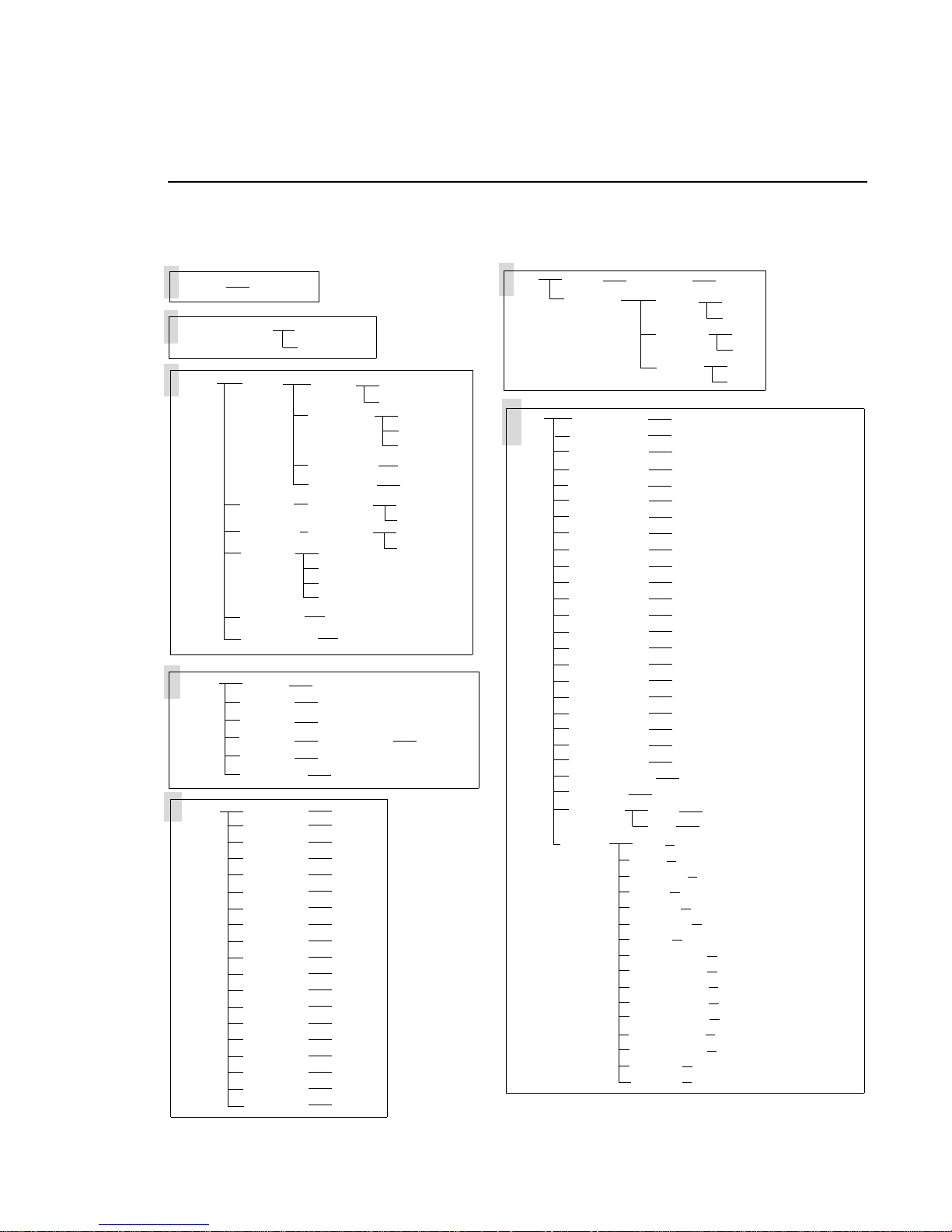
VARI❋LITE® - VL3000™ SERIES LUMINAIRE USER’S MANUAL
Menu Functions
Menu System Overview
The following is a graphic representation of the entire menu system.
Address
Setup
Config
Fixture
Manual
value
Model
Lamp
Pan/Tilt
Head Mtr
Display
ResetDef
Chg LumID value
Status
Re-Cal
Lum Id
Version
Fixt Hrs
Download
Pan
Tilt
Dimmer
Strobe
Blue
Amber
Magenta
ColWheel
CTO
Gobo1*
Index1*
Gobo2*
Index2*
Gobo3*
Index3*
Edge*
Zoom*
BeamIris*
BmSprdr**
Wash
Spot
Power
Power Up
LampHour
ResetLmp
Movement
Movement
30 Sec
5 Min
10 Min
ON
OK?
scrolls errors or displays OK
OK?
XXXXXXXX
MM/DD/YY
# hours of use
OK?
value
value
value
value
value
value
value
value
value
value
value
value
value
value
value
value
value
value
value
off
on
Lamp OFF
Cal ON
Lamp ON
# of hours
OK?
Enable
Disable
Enable
Disable
XX:XX
DMX
Test
Data Chan XXX data
Pan/Tilt
All @1
All SEQ
Pan/Tilt
Pan
Tilt
Dimmer
Strobe
Blue
Amber
Magenta
ColrMix
CTO
ColorWhl
RotGobo1*
GobIndx1*
RotGobo2*
GobIndx2*
RotGobo3*
GobIndx3*
Edge*
Zoom*
Beam Iris*
BeamSprdr**
Lamp
Encoder
Sensor
* Spot Model Only
Swap
Inv Pan
Inv Tilt
RUN TEST
RUN TEST
RUN TEST
RUN TEST
RUN TEST
RUN TEST
RUN TEST
RUN TEST
RUN TEST
RUN TEST
RUN TEST
RUN TEST
RUN TEST
RUN TEST
RUN TEST
RUN TEST
RUN TEST
RUN TEST
RUN TEST
RUN TEST
RUN TEST
RUN TEST
RUN TEST
RUN TEST
Pan
Tilt
Pan
Tilt
Dimmer
Blue
Amber
Magenta
CTO
ColorWhl
RotGobo1*
RotGobo2*
RotGobo3*
GobIndx1*
GobIndx2*
GobIndx3*
Edge*
Zoom*
value
value
SENS TST/PASS/FAIL
SENS TST/PASS/FAIL
SENS TST/PASS/FAIL
SENS TST/PASS/FAIL
SENS TST/PASS/FAIL
SENS TST/PASS/FAIL
SENS TST/PASS/FAIL
SENS TST/PASS/FAIL
SENS TST/PASS/FAIL
SENS TST/PASS/FAIL
SENS TST/PASS/F AIL
SENS TST/PASS/FAIL
SENS TST/PASS/FA IL
** Wash Model Only
OFF
ON
OFF
ON
OFF
ON
SENS TST/PASS/FA IL
SENS TST/PASS/FAIL
SENS TST/PASS/F AIL
44 20-Aug-03 02.9678.0001 A
Page 63
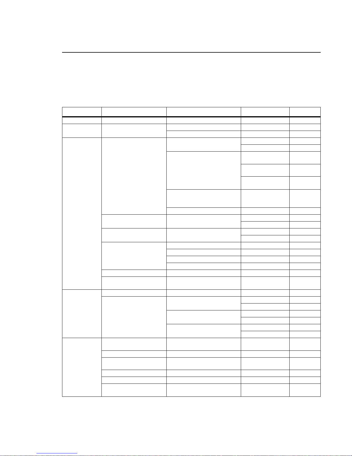
MENU SYSTEM : MENU FUNCTIONS
Menu System Function Chart
The following is a detaile d look at the internal menu system.
Table 4-1: VL3000 Menu System Chart
1st Level 2nd Level 3rd Level 4th Level 5thLevel
Address XXX Address value
Setup Model
Config
Configuration
DMX
DMX Data
Fixture Status Status/Error Display Scrolls error messages or
Luminaire Type Wash
Spot
Lamp Options Power Lamp Power ON (default)
LAMP
OFF
Power UP
LampHour Lamp Hours Used XXXX Cumulative #
ResetLmp Reset Lamp OK?
Pan and Tilt Movement Position Recovery Enable Enable
Pan/Tilt
Head Mtr Head Motor Movement Head Movement Enable Enable
Display
Display Illumination 30 Sec OFF in 30 seconds
5 Min
10 Min
ON
ResetDef
Chg LumID
Luminaire ID
DATA * Chan XXX
Pan/Tilt
Options
Re-Cal Recalibrate OK?
Lum Id
Version
Fixt Hrs Fixture Hours XXXX # Hours of Use
Download
Software
Reset Default OK?
Change
Pan and Tilt
Luminaire ID XXXXXXXX Luminaire ID
Version MM/DD/YY (Page 1) HH:MM (Page 2)
Download
XXXX Value (for future use)
Swap Swap Pan & Tilt ON
Inv Pan
Inv Tilt
displays
Number
OK?
Lamp Power-up State Lamp OFF Lamp
Off
Cal ON
After Calibration
Lamp ON
(default)
of Operation Hours
(Not editable)
Disable
Disable
OFF in 5 minutes
OFF in 10 minutes
ON indefin itely
DMX Channel XXXX Value
OFF
Invert Pan ON
OFF
Invert Tilt ON
OFF
OK
Lamp On
Lamp On
Disable
Disable
4
02.9678.0001 A 20-Aug-03 45
Page 64

VARI❋LITE® - VL3000™ SERIES LUMINAIRE USER’S MANUAL
Table 4-1: VL3000 Menu System Chart
1st Level 2nd Level 3rd Level 4th Level 5thLevel
Test All @1 Test All mechanisms
at once, 2 steps
All SEQ
T es t all
mechanisms in order, X
steps.
Pan/Tilt RUN TEST
Pan RUN TEST
Tilt RUN TEST
Dimmer RUN TEST
Strobe RUN TEST
Blue RUN TEST
Amber RUN TEST
Magenta RUN TEST
ColrMix RUN TEST
CTO RUN TEST
ColorWh1 RUN TEST
RotGobo1 (Spot Only) RUN TEST
GobIndx1 (Spot Only) RUN TEST
RotGobo2 (Spot Only) RUN TEST
GobIndx2 (Spot Only) RUN TEST
RotGobo3 (Spot Only) RUN TEST
GobIndx3 (Spot Only) RUN TEST
Edge (Spot Only) RUN TEST
Zoom (Spot Only) RUN TEST
Beam Iris (Spot Only) RUN TEST
BmSprdr
Lamp
executes Home position.
Encoder Pan XXXX
Sensor Pan SENS TST
(Wash Only) RUN TEST Run-Test in Progress
Disables Pan/Tilt and
RUN TEST Run-Test in Progress Press [Menu] to
RUN TEST Run-Test in Progress
Run-Test in Progress
Run-Test in Progress
Run-Test in Progress
Run-Test in Progress
Run-Test in Progress
Run-Test in Progress
Run-Test in Progress
Run-Test in Progress
Run-Test in Progress
Run-Test in Progress
Run-Test in Progress
Run-Test in Progress
Run-Test in Progress
Run-Test in Progress
Run-Test in Progress
Run-Test in Progress
Run-Test in Progress
Run-Test in Progress
Run-Test in Progress
Run-Test in Progress
RUN TEST Run-Test in Progress
Tilt XXXX
Tilt SENS TST
Dimmer SENS TST
Blue SENS TST
Amber SE NS TST
Magenta SENS TST
CTO Color Temperature Orange SENS TST
ColorWhl Color Wheel SENS TST
RotGobo1
RotGobo2
RotGobo3
GobIndx1
(Spot Only)
GobIndx2
(Spot Only)
GobIndx3
(Spot Only)
Edge
Zoom (Spot Only) STST
Gobo 1 (Spot Only) SENS TST Sensor PASS/FAIL
Gobo 2 (Spot Only) SENS TST Sensor PASS/FAIL
Gobo 3 (Spot Only) SENS TST Sensor PASS/FAIL
Gobo 1 Index
Gobo 2 Index
Gobo 3 Index
(Spot Only) STST Sensor Test PASS/FAIL
stop tests
Value
Value
Sensor PASS/FAIL
Sensor PASS/FAIL
Sensor PASS/FAIL
Sensor PASS/FAIL
Sensor PASS/FAIL
Sensor PASS/FAIL
Sensor PASS/FAIL
Sensor PASS/FAIL
SENS TST Sensor PASS/FAIL
STST Sensor Test PASS/FAIL
STST Sensor Test PASS/FAIL
Sensor Test PASS/FAIL
46 20-Aug-03 02.9678.0001 A
Page 65

MENU SYSTEM : MENU FUNCTIONS
Table 4-1: VL3000 Menu System Chart
1st Level 2nd Level 3rd Level 4th Level 5thLevel
Manual
Manual
Commands
Pan * XXXX Value
Tilt * XXXX Value
Dimmer XXX Value
Strobe XXX Value
Blue XXX Value
Amber XXX Val ue
Magenta XXX Value
ColWheel Color Wheel XXX Value
Color Temperature
CTO
Orange
Gobo1 (Spot Only) XXXX Value
Index1 (Spot Only) XXX Value
Gobo2 (Spot Only) XXX Value
Index2 (Spot Only) XXX Value
Gobo3 (Spot Only) XXX Value
Index3 (Spot Only) XXX Value
Edge (Spot Only) XXX Value
Zoom (Spot Only) XXX Value
BeamIris (Spot Only) XXX Value
BmSprdr
(Wash Only)
Beam Spreader
XXX Value
XXX Value
4
* For 16-bit parameters, the data displayed will be scaled to a range of 0-4095.
02.9678.0001 A 20-Aug-03 47
Page 66

VARI❋LITE® - VL3000™ SERIES LUMINAIRE USER’S MANUAL
Menu Function Definitions
For easy reference, each possible menu item is listed alphabetically in the first column by its display
abbreviation. The second c olumn fol lows with a definiti on of the abbrevi atio n and then a t hird column
provides an explanation of its purpose and function.
Table 4-2: Menu Function Definitions
Display Definition Purpose
10 Min 10 Minutes Sets Menu Display to automatically shut off after 10 minutes of non-use.
30 Sec 30 Seconds Sets Menu Display to automatically shut off after 30 seconds of non-use.
5 Min 5 Minutes Sets Menu Display to automatically shut off after 5 minutes of non-use.
Address Address Accesses option for setting luminaire DMX starting address.
All @1 All At Once Tests all internal mechanisms at once, in two steps.
All SEQ All Sequence Tests all internal mechanisms in sequence for X steps.
Amber Amber Specifies am be r color p ara meter for manual control (Manual) or testing (Test).
Beam Iris Beam Iris Specifies beam iris mechanism for testing (Test).
BeamIris Beam Iris Specifies beam iris mechanism for manual control (Manual).
Blue Blue Specifies blue color parameter for manual control (Manual) or testing (Test).
BmSprdr Beam
Spreader
Cal ON Calibration On Configures arc luminaire so that lamp will strike after calibration.
Chan XXX DMX Channel Specifies DMX channel for display of current data value.
Chg LumID Change
Luminaire ID
ColrMix Color Mixer Specifies color mixing mechanism for testing (Test).
ColorWhl Color Wheel Specifies color wheel for manual control (Manual) or testing (Test).
Config System
Configuration
CTO CTO Function Specifies CTO (color temperature orange) parameter for manual control (Man-
Data DMX Data Access es option for setting DMX address channel.
Dimmer Dimmer Specifies dimmer mechanism for manual control (Manual) or testing (Test).
Disable Disable Disables a function.
Display Display Accesses options for Menu Display illumination defaults.
DMX DMX Accesses options for DMX system settings.
Download Download Initiates download of luminaire software.
Edge Edge Specifies edge function for manual control (Manual) or testing (Test).
Enable Enable Enables a function.
Encoder Encoder Accesses pan/tilt encoders for diagnostic testing.
FAIL Test Fail Indicates that a test has failed.
Fixt Hrs Fixture Hours Displays total number of hours luminaire has been powered on.
Fixture Fixture Accesses luminaire information such as serial number, software version, and
GobIndxX Gobo Index Specifies gobo index EOT sensor for testing. (X = 1, 2 or 3)
Specifies beam spreader mechanism for manual control (Manual) or testing
(Test).
For future use.
Accesses options for setting lamp, pan/tilt, and Menu Display defaults. Also
accesses lamp information such as number of hours used, along with its
respective reset function.
ual) or testing (Test).
total operation hours. Also accesses recalibration and download options.
48 20-Aug-03 02.9678.0001 A
Page 67

MENU SYSTEM : MENU FUNCTIONS
Table 4-2: Menu Function Definitions (Continued)
Display Definition Purpose
GoboX Gobo Wheel Specifies one of three rotating gobo wheels for manual control. (X = 1, 2 or 3)
Head Mtr Head Motor Configures head movement options.
IndexX Gobo Index Specifies rotating gobo index for manual control. (X = 1, 2 or 3)
Inv Pan Invert Pan Reverses pan action for special focus requirements.
Inv Tilt Invert Tilt Reverses tilt action for special focus requirements.
Lamp Lamp Accesses lamp power-up options, reset and information (Config) or tests
Lamp function (Test).
Lamp OFF Lamp is Off Configures arc luminaire so that lamp will not strike upon power up.
Lamp ON Lamp is On Configures arc luminaire so that lamp will strike upon power up.
LampHour Lamp Hours Displays total number of lamp operating hours.
Lum Id Luminaire ID Displays unique luminaire ID number.
Magenta Magenta Specifies magenta parameter for manual control (Manual) or testing (Test).
Manual Ma nual Accesses options for luminaire mechanism control by entry of data values.
Movement Movement Enables or disables pan and tilt movement.
OFF Off Turns off a function.
OK Okay Indicates calibration has completed and no errors have occurred.
OK? Okay? Prompt for pressing [Enter] before an action is executed.
ON On Indefinitely Sets Menu Display to stay on until programmed otherwise (Display) or turns
on a function.
Pan Pan Specifies pan function for manual control (Manual) or testing (Test).
Pan/Tilt Pan/Tilt Accesses pan and tilt options for focus swap function, movement enable/dis-
able, manual control and testing.
PASS Test Pass Indicates that a test has passed.
Power Lamp Power Accesses options to turn lamp on or off.
Power Up Power Up Accesses options for lamp power up state.
PROG Programming Currently programming the new version of software.
Re-Cal Recalibrate Recalibrates luminaire.
ResetDef Reset Defaults Resets default system configuration values.
ResetLmp Reset Lamp Resets lamp hour and strike counters. (For use when new lamp is installed.)
RotGoboX Rotating Gobo Specifies rotating gobo for testing (Test). (X = 1, 2 or 3)
RUN TEST Run Test Indicates that a mechanism test is in progress.
Sensor Sensors Accesses sensor types for diagnostic testing.
Setup Setup Accesses unit model type options (do not change).
Status Status/Error Allows scrolling through error list or displays OK if no errors.
Strobe Strobe Sp ec ifie s stro be fun cti on for man ual contro l (Manual) or testing (Test).
STST Sensor Test Indicates that a system sensor test is in progress.
Swap Swap Swaps pan/tilt action for special focus requirements.
Test Test Accesses diagnostic tests for internal mechanisms.
Tilt Tilt Specifies tilt function for manual control (Manual) or testing (Test).
Version Version Displays current software version date and time (in two pages).
Zoom Zoom Function Specifies zoom function for manual control (Manual) or testing (Test).
4
02.9678.0001 A 20-Aug-03 49
Page 68
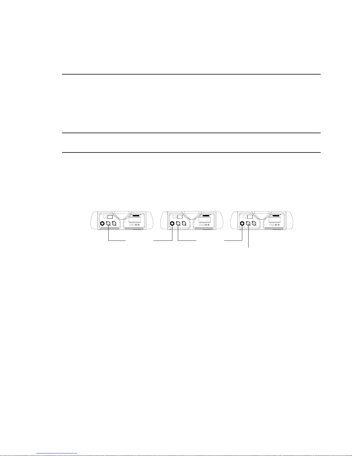
VARI❋LITE® - VL3000™ SERIES LUMINAIRE USER’S MANUAL
Self-Tests
Running Parameter Tests
The luminaire is capable of running self-tests by using the Test menu functions.
When running tests on mul tiple luminaires, a male ter mination connector is requ i red at the last
luminaire in the link. Refer to “Connecting Data and Power” on page 14 for more information
regarding the construction of this connector.
Note: After 10 seconds of inactivity, the menu display will change to the default state showing the
address.
To connect luminaires for simultaneous testing:
Step 1. At last luminaire, install male termination connector into DATA THRU XLR connector.
Step 2. At master luminaire Menu Display, press [Menu].
Master Luminaire Luminaire 1 Luminaire 2
AC PWR
~
DATA THRU
DATA IN
AC IN
ENTERMENU
Data Thru
AC PWR
~
DATA THRU
DATA IN
AC IN
ENTERMENU
Data Thru
AC PWR
~
DATA THRU
DATA IN
AC IN
ENTERMENU
Termination Connector
Figure 4-2: Testing Setup
To run tests:
Step 1. Press [Menu].
Step 2. Press [Up] / [Down] arrows until Test appears. Press [Enter].
Step 3. Use [Up] / [D own] arrows to select a parameter to test. Refer to “Menu System Function
Chart” on page 45 for a complete list of test parameters which can be chosen.
Step 4. Press [Enter] to run test.
Step 5. Press [Menu] to stop test at any time.
50 20-Aug-03 02.9678.0001 A
Page 69

MENU SYSTEM : SELF-TESTS
4
Movement Disable
The Movement option allows pan and tilt to be disabled so that the luminaire can be placed in any
position for testing without movement occurring. In order to regain full control of the luminaire,
Movement will need to be enabled after testing.
Note: When using the Movement option, pan and tilt will be disabled for all the luminaires that are
linked.
To set movement option:
Step 1. Press [Menu].
Step 2. Press [Up] / [Down] arrows until Co nfig appears. Press [Enter].
Step 3. Press [Up] / [Down] arrows until Pan/Tilt appears. Press [Enter].
Step 4. Movement will be displayed. Press [Enter].
Step 5. Use [Up] / [Down] arrows to select Enable or Disable. Press [Enter] to select.
02.9678.0001 A 20-Aug-03 51
Page 70

VARI❋LITE® - VL3000™ SERIES LUMINAIRE USER’S MANUAL
Notes
52 20-Aug-03 02.9678.0001 A
Page 71
APPENDIX A.
Troubleshooting and
Maintenance
This appendix provides instructions for troubleshooting and routine maintenance which may be
necessary during the life of the luminaire.
• Troubleshooting
• Routine Maintenance
WARNING: All maintenance procedures are to be performed with power removed from the
luminaire. Never remove covers or backcap while lamp is in operation.
02.9678.0001 A 20-Aug-03 53
Page 72

VARI❋LITE® - VL3000™ SERIES LUMINAIRE USER’S MANUAL
Troubleshooting
Er ror Messages
If a problem occurs during luminaire calibration, at the end of the calibration sequence the Menu
Display will cycle through any applicable error message(s) until the end of the list is reached. To
review the error messages again, it will be necessary to access them using the Stat us function.
To access error messages:
Step 1. Press [Menu].
Step 2. Press [Up] / [Down] arrows until Fixture appears. Press [Enter].
Step 3. Press [Up]/ [Down] arrows to access Status. P ress [Enter]. (Display will now scroll
through any error messages or display OK if no errors.)
Table A-1: Error Messages
Display Message
OK No Errors Found
Pan/No Sens Pa n sensor not found.
Pan/Encoder/Fail Pan encoder failure.
Tilt/No Sens Tilt sensor not found.
Tilt/Encoder/Fail Tilt encoder failure.
Index1/No Sens Gobo 1 Index sensor not found.
Gobo1/No Sens Rotating Gobo 1 sensor not found.
Index2/No Sens Gobo 2 Index sensor not found.
Gobo2/No Sens Rotating Gobo 2 sensor not found.
Index3/No Sens Gobo 3 Index sensor not found.
Gobo3/No Sens Rotating Gobo 3 sensor not found.
Dimmer/No Sens Dimmer sensor not found.
Blue/No Sens Blue sensor not found.
Amber/No Sens Amber sensor not found.
Magenta/No Sens Magenta sensor not found.
ColWheel/No Sens Color wheel sensor not found.
CTO/No Sens CTO sensor not found.
Zoom/No Sens Zoom sensor not found.
Edge/No Sens Edge sensor not found.
54 20-Aug-03 02.9678.0001 A
Page 73

TROUBLESHOOTING AND MAINTENANCE
Troubleshooting Guide
If a problem is suspected, first try recalibrating the luminaire to prompt an error message. The chart
below provides possible causes and remedies for various error messages and/or symptoms.
Table A-2: Troubleshooting Chart
Message Description Symptom Possible Cause/Remedy
Lamp
Power
Douse
n/a Lamp Douse Lamp douses frequently Fan failure...
n/a Lamp Strike Fa ilure Lamp will not strike Lamp cutout switch engaged...
n/a Profile Not Matched Luminaire behaves
n/a No power Luminaire does not
n/a DMX Data Input Self tests will not run or
n/a DMX Failure No response to DMX
n/a DMX Termination Erratic control of lumi-
Lamp Off option is configured
Lamp does not strike
upon start-up
oddly
power up
software downloa d does
not work.
data
naire
- Reconfigure lamp startup option in Lamp config
menu.
- check fans for proper connection and operation.
- check lamp cutout switches at lamp box and fan
ducts.
Bad lamp...
- replace lamp.
Profile not set correctly...
- check Setup menu for correct type (spot or
wash).
Switch not turned on...
- verify switch is turned on.
Not plugged in...
- ensure A/C cable is connected to power source.
Detecting DMX data...
- disconnect DMX input cable.
MCB connector disconnected...
- check MCB DATA IN connection.
No DMX termination or termination not correct...
- check for DMX terminator.
A
02.9678.0001 A 20-Aug-03 55
Page 74
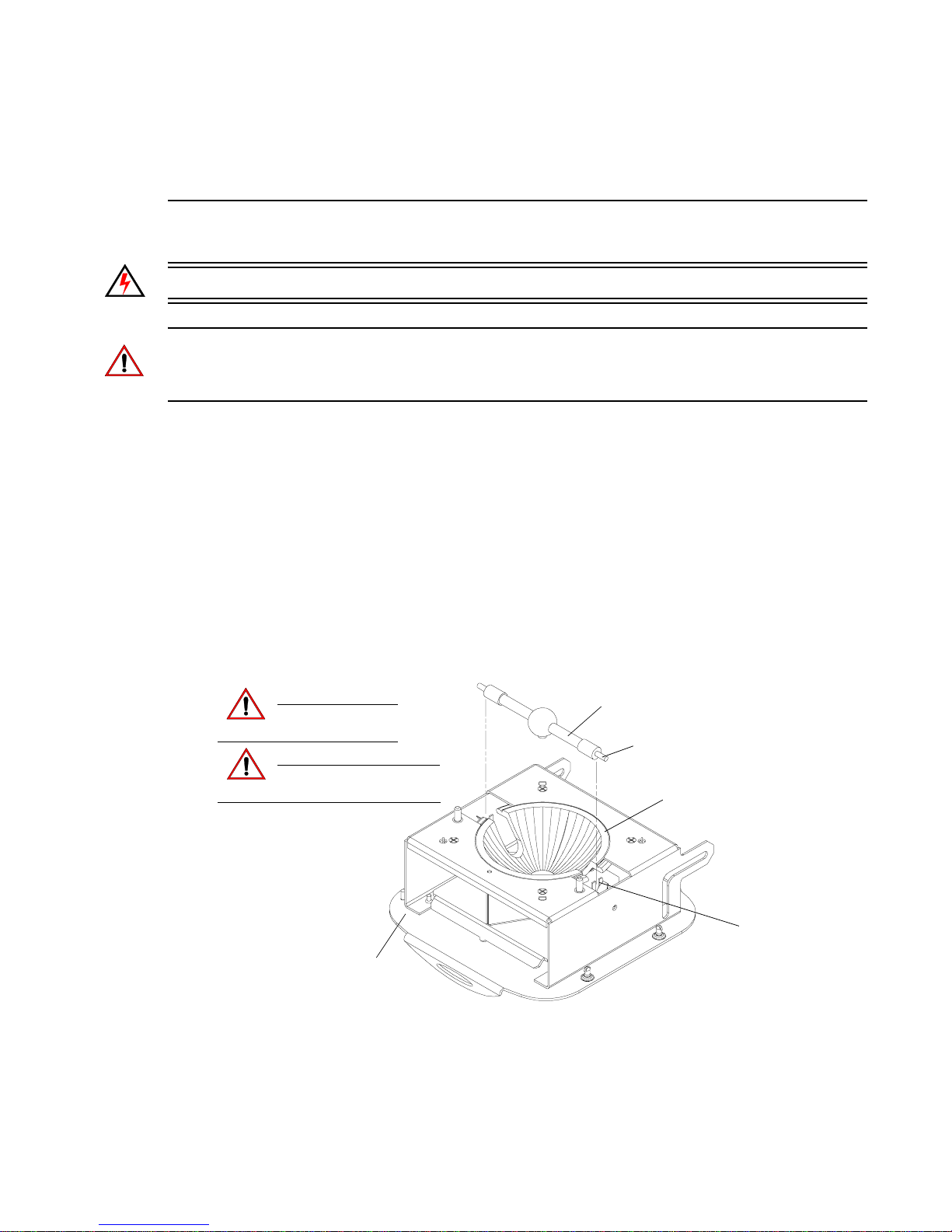
VARI❋LITE® - VL3000™ SERIES LUMINAIRE USER’S MANUAL
Routine Maintenance
Lamp Replacement
WARNING: Ensure that power is removed from luminaire when installing lamp.
CAUTION: Wear cotton gloves or other covering while installing lamp. Touching lamp glass with
bare fingers will leave oil and may cause the lamp to explode or reduce lamp life. If touched, use
alcohol and cotton cloth to thoroughly clean glass portion of lamp.
To replace lamp:
Step 1. Ensure power is removed from luminaire.
Step 2. At rear of luminaire he ad, l oos en four 1/4-turn screws and slide la mp box bac k and out (it is
hinged).
Step 3. One side at a time, press lamp lock lever forward and remove current lamp.
Step 4. Position new lamp with dimpl e side down. On e side at a ti me, pr ess l amp lock lever forwar d
and insert lamp connector. Ensure lamp is seated fully in place.
Step 5. Close lamp box and re-tighten 1/4-turn screws.
Step 6. Align lamp as detailed in “Align Lamp” on page 57.
Lamp (dimple side down)
Allow lamp to cool
CAUTION:
CAUTION:
before servicing.
Do not touch lamp or
reflector with bare fingers.
Lamp Box
Lamp Connector
Reflector
Lock Lever
56 20-Aug-03 02.9678.0001 A
* Luminaire Head Not Shown For Clarity
Figure A-1: Installing Lamp
Page 75
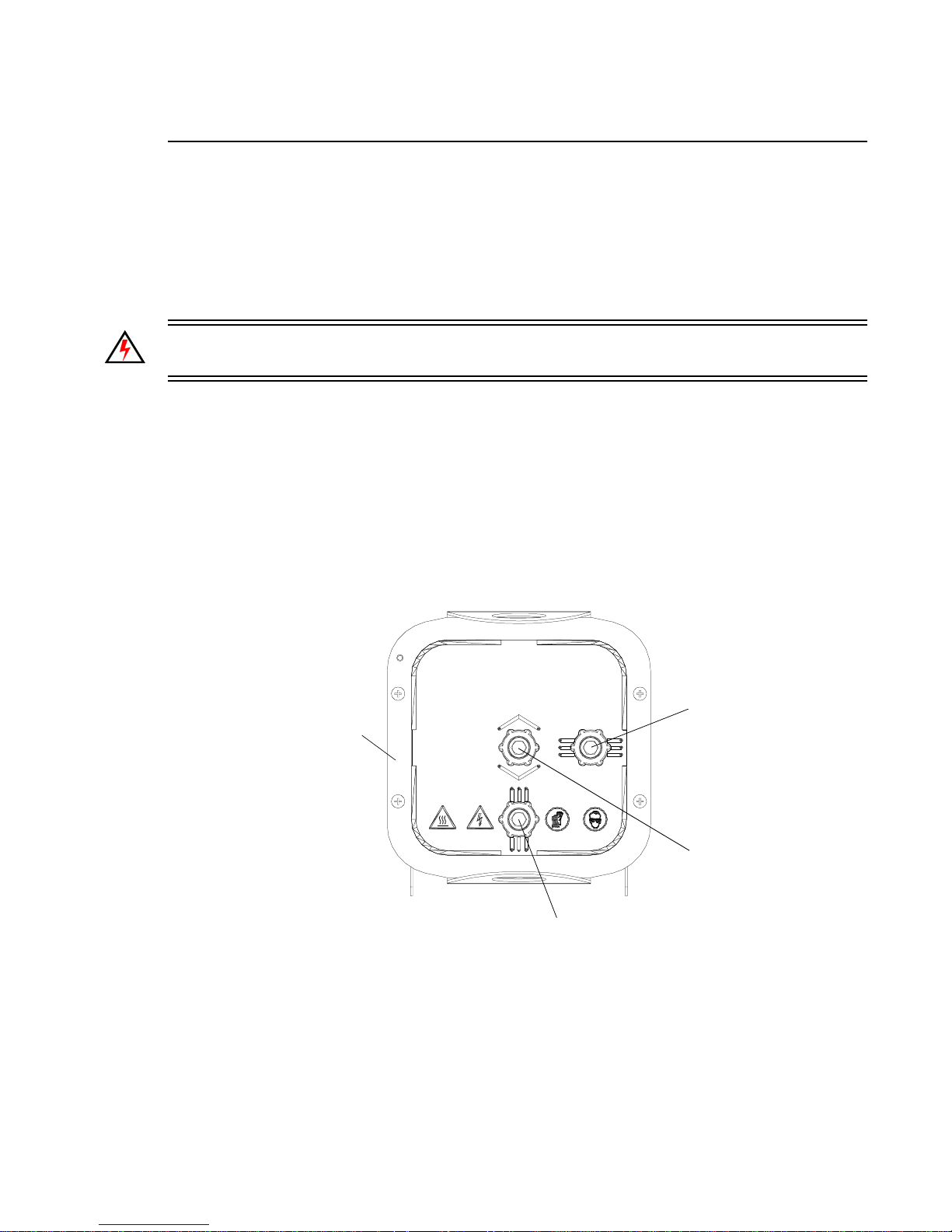
TROUBLESHOOTING AND MAINTENANCE
A
Align Lamp
The design of the VL3000 luminaire optical system all ows f or a f la t o r peaked field. A flat field is on e
where ther e is no detectable hot spot and a peaked field is one where the intensity of the beam is
greater at the center of the beam than at the perimeter.
After a new lamp is installed, it will be necessary to align the lamp to optimize the beam. Knobs
located at the luminaire’s backcap will allow adjustment.
WARNING: Backcap and adjustment knobs will be HOT during lamp operation. Wear gloves to
prevent burns.
To align lamp:
Step 1. Power-up luminaire.
Step 2. At Menu Display , select Lamp from Config menu (refer to “Menu Operation” on page 42).
(If using console, set intensity to 100%, open beam size iris and focus for hard edge.)
Step 3. Position beam on a white wall at a distance of 10 to 20 feet.
Step 4. At backcap, using X, Y and Z adjustment screws, adjust beam as required.
CAUTION:
SFc10-4 BASE.
ATTENTION:
TYPE H, 1200 WATT, 100V ET UN SUPPORT SFc10-4.
CAUTION:
Y
X
Z
Backcap
RISK OF FIRE. USE ONLY 1200 WATT, H TYPE 100V METAL HALIDE LAMP,
RISQUE D'INCENDIE. UTILISER UNIQUEMENT UNE LAMPA HALOGENE EN METAL DE
RISK OF EXPOSURE TO EXCESSIVE ULTRAVIOLET RADIATION. DO NOT OPERATE
WITHOUT COMPLETE LAMP ENCLOSURE IN PLACE OR WHEN LENS IS DAMAGED.
DISCONNECT FIXTURE
BEFORE RELAMPING
CAUTION:
HOT LAMP
DO NOT OPEN FOR 5 MINUTES
AFTER SWITCHING OFF.
Figure A-2: Aligning Lamp
02.9678.0001 A 20-Aug-03 57
Page 76
VARI❋LITE® - VL3000™ SERIES LUMINAIRE USER’S MANUAL
Gobo Replacement
Tools:
#2 Phillips screwdriver
WARNING: Remove power from luminaire before performing maintenance. Gobos may be HOT
after operation. Allow to cool before replacing.
To replace a gobo:
Step 1. Remove power from luminaire.
Step 2. Remove appropriate head cover by loosening four 1/4-turn screws:
a. To access Wheels 1 and 3, remove bottom cover as shown in Figure A-3.
b. To access Wheel 2, remove top cover as shown in Figure A-3.
Step 3. If accessing Wheels 1 and 3, also raise hinged fan duct assembly. (Fan duct has a lamp
cutoff switch which will disengage power to lamp.)
Step 4. Rotate gobo wheel until required gobo position is accessible.
CAUTION: Do not push on gobo glass. Press on gobo carrier only.
CAUTION: Do not touch gobos with bare fingers. Wear cotton gloves or other covering while
replacing. Clean with glass cleaner and soft cloth if required.
Step 5. Remove current gobo by carefully pressing on edges of gobo carrier with fingers, pressing
gobo toward front end of luminaire (toward lens), and out of wheel.
Step 6. Install new gobo as follows:
a. Align three tabs on gobo carrier with three notches in wheel (gobo can only be oriented
in one direction).
b. Insert gobo carrier into wheel, ensuring that carrier snaps into place.
Step 7. Close fan duct assembly and replace covers.
58 20-Aug-03 02.9678.0001 A
Page 77
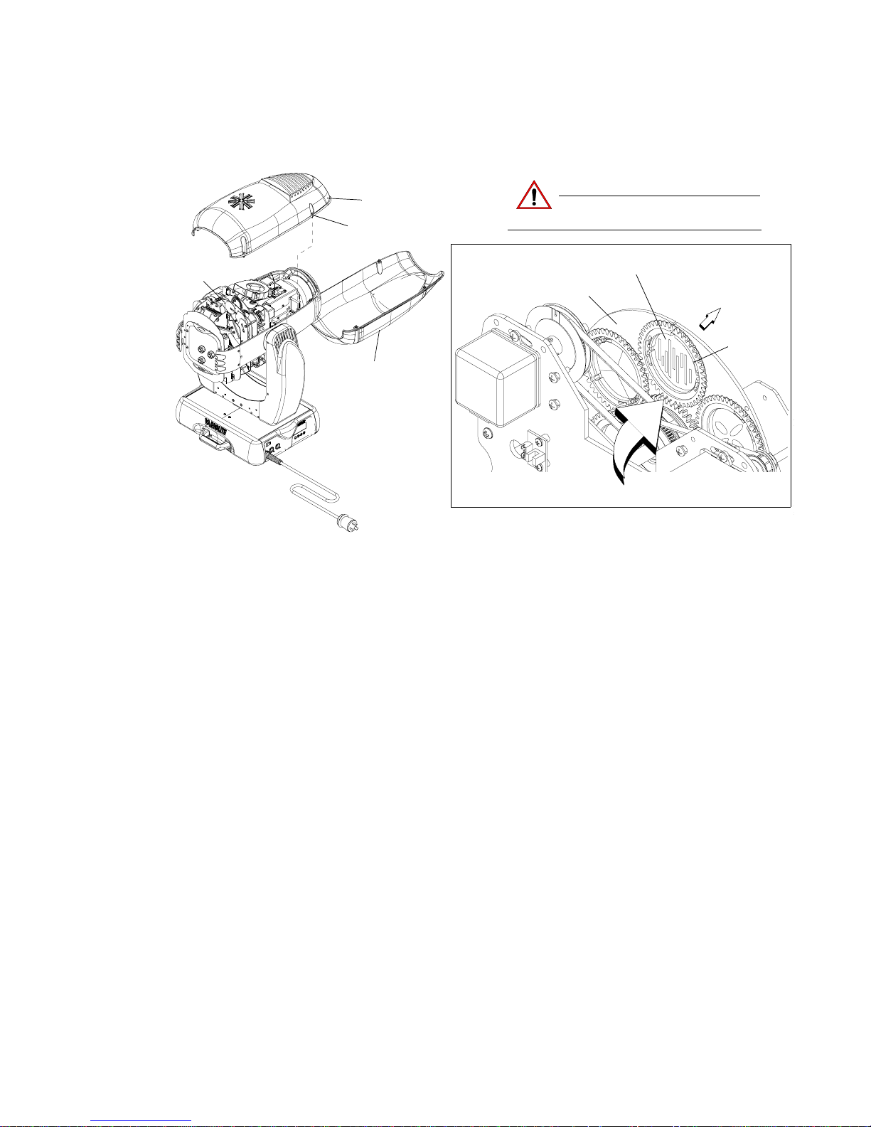
TROUBLESHOOTING AND MAINTENANCE
A
Gobo Wheel
(see detail)
Top Head Cover *
1/4-Turn Screw
Bottom Head Cover *
* Head covers are attached by tethers.
Figure A-3: Replacing a Gobo
CAUTION:
Gobo Wheel
Do not touch glass with bare fingers.
Press on gobo carrier only.
Gobo Assembly
Front of luminaire
Carrier
Press from this side
02.9678.0001 A 20-Aug-03 59
Page 78
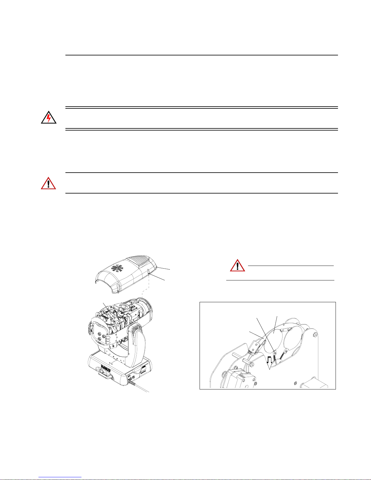
VARI❋LITE® - VL3000™ SERIES LUMINAIRE USER’S MANUAL
Color Filter Replacement
Tools:
#2 Phillips screwdriver
WARNING: Remove power from luminaire before performing maintenance. Filters may be HOT
after operation. Allow to cool before replacing.
To replace a co lor filter:
Step 1. Remove power from luminaire.
Step 2. Remove top head cover by loosening four 1/4-turn screws as shown in Figure A-4.
CAUTION: Do not touch filters with bare fingers. Wear cotton gloves or other covering while
replacing. Clean with glass cleaner and soft cloth if required.
Step 3. Rotate color wheel until required filter position is accessible.
Step 4. Press spring lock back until color filter is free and remove filter.
Step 5. Install new filter (orientation does not matter) ensuring that it is securely in position.
Step 6. Replace head cover.
Color Wheel
(see detail)
Top Head Cover *
CAUTION:
1/4-Turn Screw
* Head covers are attached by tethers.
Spring Loc k
Color Wheel
Do not touch filter with bare fingers.
Wear cotton gloves.
Color Filter
Push spring lock back
to release color filter
60 20-Aug-03 02.9678.0001 A
Figure A-4: Replacing a Color Filter
Page 79
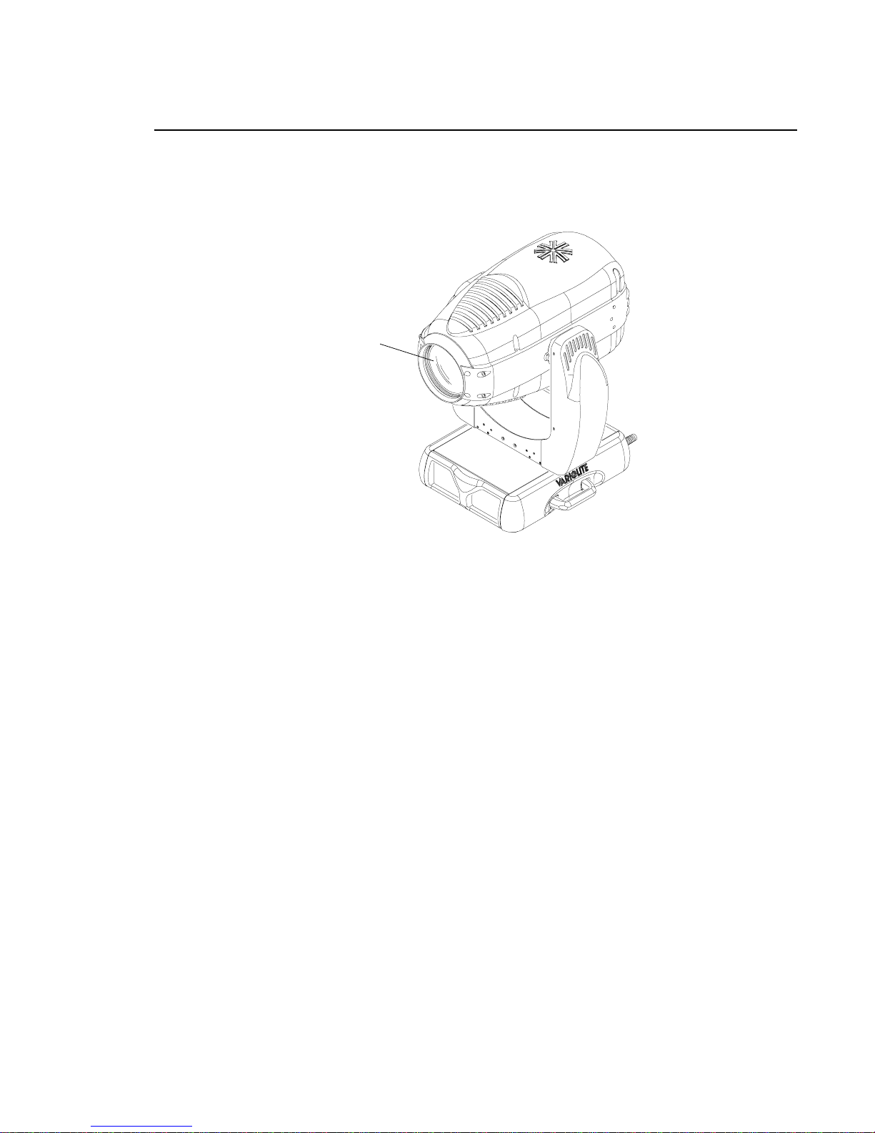
TROUBLESHOOTING AND MAINTENANCE
Cleaning Front Lens
The front lens can be cleaned using a common glass cleaner and a soft, lint-free cloth.
Front Lens
A
Figure A-5: Cleaning Front Lens
02.9678.0001 A 20-Aug-03 61
Page 80

VARI❋LITE® - VL3000™ SERIES LUMINAIRE USER’S MANUAL
Notes
62 20-Aug-03 02.9678.0001 A
Page 81

APPENDIX B.
Technical Specifications
VL3000 Spot Luminaire
PROGRAMMABLE FUNCTIONS
Zoom Optics
13-element 6:1 zoom optics system covering a range of 10° to 60°.
Color System
A three-filter CYM cross-fading mechanism. A fixed color wheel with six interchangeable color
filters and continuous wheel rotation for additional effects. It includes a variable CTO color
temperature correcti on filt er.
Beam Size Control
A mechanical iris provides continuous beam size control for both rapid changes and smooth timed
beam angle changes.
Intensity Control
Full field dimming designed for both smooth timed fades and quick dimming effects.
Strobe
High-performance dual blade strobe system capable of ultra-fast operation.
Rotating Gobo Wheels
14 rotatable, indexable gobo positions available across three wheels: two, six-position gobo
wheels with five rotatable, indexable gobo positions and one open position, and one, five-position
gobo wheel with four rotatable, indexable positions and one open position.
Edge and Pattern Focus
Variable beam focus to soften edges of gobos or spots. Remarkable depth of field capability allows
morphing effects between all pattern and effects wheels.
Pan and Tilt
Smooth, time-continuous motion using stepper motors with encoder correction. Pan range is 540°,
Tilt range is 270°. 0.3° resolution.
02.9678.0001 A 20-Aug-03 63
Page 82
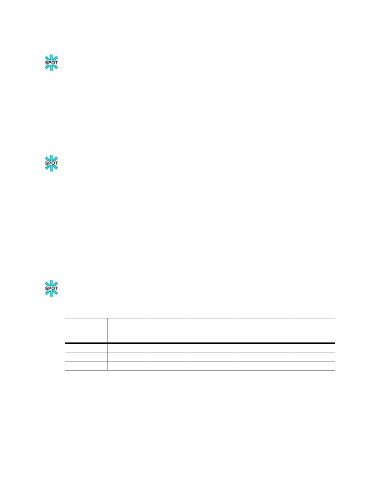
VARI❋LITE® - VL3000™ SERIES LUMINAIRE USER’S MANUAL
OPTICAL
Source
Osram HMI 1200 W/S Metal Halide Lamp, 6000°K, 85CRI
Output
24,000 lumens
Reflector
Precision glass reflector with dichroic cold mirror coating.
Color Filter
Fixed wheel color filters: .044" thick, 2.039" diameter.
Gobo
Gobos are E size. Metal gobos are not acceptable.
OPERATIONAL
Power Requirements
Standard AC power distribution from 180-264 VAC, 50/60 Hz. The unit requires 10 A.
Operational Temperature
-20° to 122°F (-29° to 50°C)
Cooling
Forced air cooled.
Control
Compatible with a wide variety of DMX512 consoles.
Weight
82 lbs. (37 kg) with rails.
Spacing
Hangs on 26.0 inch (66 cm) centers. All models can be mounted and operated in any orientation.
PHOTOMETRIC
VL3000 Spot Luminaire - 1200W Metal Halide
Fixture output = 24,000 lumens. All data taken with a seasoned light source at 20 hours of life.
Zoom Lens
Position
NFOV 1,201,000 9.0 0.157 10.0 0.175
MFOV 104,400 31.0 0.555 35.0 0.631
WFOV 40,930 46.0 0.849 56.0 1.063
CANDELA
(cd)**
BEAM
ANGLE
(degrees)
BEAM
DIAMETER
TN*
FIELD ANGLE
(degrees)
* Multiply throw distance by Tn to determine coverage.
cd
** To calculate center beam illuminance (I) at a specific distance (D):
I =
2
D
-- if (D) is in feet, (I) is in foot candles
-- if (D) is in meters, (I) is in lux
FIELD
DIAMETER
TN*
64 20-Aug-03 02.9678.0001 A
Page 83

TECHNICAL SPECIFICATIONS
B
VL3000 Wash Luminaire
PROGRAMMABLE FUNCTIONS
Color System
A three-filter CYM cross-fading mechanism. A fixed color wheel with six interchangeable color filters
and continuous wheel rotation for additional effects. It includes a variable CTO color temperature
correction filter.
Beam Size Control
A zoomable beam spreader mechanism provides continuous beam size control for both rapid changes
and smooth timed beam angle changes.
Intensity Control
Full field dimming designed for both smooth timed fades and quick dimming effects.
Strobe
High-performance dual blade strobe system capable of ultra-fast operation.
Pan and Tilt
Smooth, time-continuous motion using stepper motors with encoder correction. Pan range is 540°, Tilt
range is 270°. 0.3° resolution.
OPTICAL
Source
Osram HMI 1200 W/S Metal Halide Lamp, 6000°K, 85CRI
Output
35,000 lumens
Reflector
Precision glass reflector with dichroic cold mirror coating.
OPERATIONAL
Power Requirements
Standard AC power distribution from 180-264 VAC, 50/60 Hz. The unit requires 7 to 12 A depending
on the AC supply voltage.
Operational Temperature
-20° to 122°F (-29° to 50°C)
Cooling
Forced air cooled.
Control
Compatible with a wide variety of DMX512 consoles.
Weight
74 lbs. (34 kg) with rails.
Spacing
Hangs on 26.0 inch (66 cm) centers. All models can be mounted and operated in any orientation.
02.9678.0001 A 20-Aug-03 65
Page 84
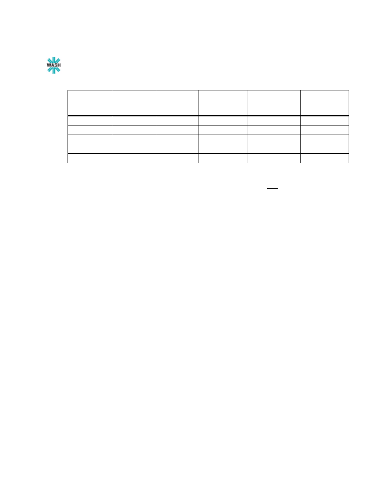
VARI❋LITE® - VL3000™ SERIES LUMINAIRE USER’S MANUAL
PHOTOMETRIC
VL3000 Wash Luminaire - 1200W Metal Halide
Fixture output = 35,000 lumens. All data taken with a seasoned light source at 20 hours of life.
Diffusion
Full Spot 1,253,000 7.5 0.131 14.0 0.246
25% Flood 495,000 10.0 0.175 22.0 0.389
50% Flood 178,000 18.0 0.317 37.5 0.679
75% Flood 94,100 25.0 0.443 49.5 0.922
Full Flood 61,100 30.5 0.545 60.0 1.155
CANDELA
(cd)**
BEAM
ANGLE
(degrees)
BEAM
DIAMETER
TN*
FIELD ANGLE
(degrees)
FIELD
DIAMETER
TN*
* Multiply throw distance by Tn to determine coverage.
cd
** To calculate center beam illuminance (I) at a specific distance (D):
I =
2
D
-- if (D) is in feet, (I) is in foot candles
-- if (D) is in meters, (I) is in lux
66 20-Aug-03 02.9678.0001 A
Page 85
Vari-Lite 10911 Petal St. Dallas, TX 75238 / 1-877-VARILITE / 214-647-8036 (fax) / [email protected]
Customer: _____________________________________________ Date: ___________________
VL3000 RMA Form
VL3000 Series
VL3000™ Series Luminaires Part Number Warranty Serial Numbers Warranty
1200W Arc Ballast w/ Rider Card 23.9661.1269
Beam Spreader Assy 21.9678.0910
Color/Dimmer/Strobe Assy 22.9678.0103
Control PCB 24.9678.0730
Display PCB 24.9678.0875
Gobo Assy 21.9678.0200
Ignitor Assy 24.9661.1126
Iris Assy 21.9678.0270
Optics Assy 22.9678.0103
Pan Motor Assy 21.9678.0864
Tilt Motor Assy 21.9678.0765
Non
Warranty
Total
Page 86

 Loading...