


VARI❋LITE® - VL2000™ WASH LUMINAIRE SERVICE MANUAL
VA R I ❋LITE®, Artisan®, VL2® and VLD® are trademarks owned by Vari-Lite, Inc., 201 Regal Row, Dallas TX 75247 USA
and are registered in the United States and other countries.
VL1000™, VL2000™, VL2201™, VL2202™, VL2400™ (and the individual product designations), VL3000™, Virtuoso™,
Virtuoso™ DX, VA R I ❋LITE Visionary
™
VL6B
, VL6C™, VL7™, VL7B™, VLM™, APS6™, C3™, ArtisanVLQ™, SPC-36™, UDM™, AutoTruss™, SmartDMX™,
Smart Repeater
DICHRO❋TUNE
™
, Series 100™, Series 200™, Series 300™, Series 2000™, Series 3000™, DICHRO❋WHEEL™,
™
, VACU❋DEP™, VARI❋IMAGE™, VARI❋BEAM™, and the Vari-Lite Asterisk are also trademarks
owned by Vari-Lite, Inc.
VA R I ❋LITE® products are protected by one or more of the following patents, and other pending patent applications worldwide:
US Patents No. 5,959,758; 5,728,994; 5,590,954;5,367,444; 5,329,431; 5,209,560; 5,186,536; 5,073,847; 5,010,459; 4,980,806;
4,602,321; 4,392,187; U.S. Design Patents No. 366,712; 359,574;
Australia Patents No. 703868; 693691; 683695; 667109; 657152; 649264; 646588; 618559; 586095; 576400; 575271; 546433;
Australia Design Reg. No. 126781;
German Patents No. (DBP) 69314122.0; 69208615.3; 69207692.1; 69121029.2; 3768727.1; 3750201.8; 3587270.5; 3279888.1;
3274291.6; DGM G9312884; DGM 9407689.8;
European Patents No. 0586049 (FR, GB); 0547732 (BE, DK, FR, GB); 0534710 (BE, FR, GB); 0474202 (BE, DK, FR, GB);
0253082 (BE, FR, GB); 0253081 (BE, FR, GB); 0192882 (BE, FR, GB); 0140994 (BE, FR, GB); 0060068 (BE, FR, GB);
France Design Reg. No. 335132 - 335147;
Spain Patents No. 2090191; 2084289; 2082384; 2058071; 2020960; 0548328; Spain Utility Model No. 2031748; Spain Design
Reg. No. 129596;
Japan Patents No. 2,059,669; 2,055,324; 2,002,168; 1,889,481; 1,770,241; 1,723,825; 1,683,007; 1,553,011; KR 206051; 181180;
76310; 47673; Japan Design Reg. No. 947552; 945436-1; 945436;
Korean Design Reg. No. 175178;
Mexico Patents No. 180148; 179138;
Taiwan Patents No. 78726; 66975; 65380; 63471; 40611; 28275;
United Kingdom Design Reg. No. 2042174; 2033108; 2029499.
™
, VL1™, VL2B™, VL2C™, VL3™, VL4™, VL5™, VL5Arc™, VL5B™, VL6™,
All other brand or product names which may be mentioned in this manual are trademarks or registered trademarks of their
respective companies or organizations.
VL2000™ Wash Luminaire Service Manual
The information furnished in this manual is for informational use only and is subject to change without notice. Vari-Lite, Inc.
assumes no responsibility or liability for any errors or inaccuracies that may appear in this manual. All information and graphic
representations are property of Vari-Lite, Inc. 201 Regal Row, Dallas, Texas 75247 USA.
Version as of: 24-March-2004
Printed in the USA.
Part number: 02.9671.0010 C
VL2000™ Wash Luminaire Service Manual
© 2000-2004 Genlyte Thomas Group LLC All Rights Reserved.
ii 24-March-2004 02.9671.0010 C

How To Obtain Warranty Service
A copy of the Vari-Lite, Inc. Limited Warranty was included in the shipping package
for this VARI❋LITE® product.
To obtain warranty service, please contact customer service at 1-877-VARI-LITE
(1-877-827-4548) or customerservice@vari-lite.com and request a Return Material
Authorization (RMA) for warranty service. You need to provide the model and serial
number of the item being returned, a description of the problem or failure and the
name of the registered user or organization. If available, you should have your sales
invoice to establish the date of sale as the beginning of the warranty period.
Once you obtain the RMA, pack the product in its original packing material along with
a copy of your invoice (if available) and write the RMA number legibly on or near the
shipping address label. Return the unit, freight prepaid to:
Vari-Lite, Inc.
10911 Petal Street
Dallas, Texas 75238
Attention: Warranty Service
FOREWORD
As stated in the warranty, it is required that the shipment be insured and FOB our
service center.
Confidential Property Disclosure
This technical manual is confidential property of Genlyte Thomas Group LLC All
information contained herein is the sole and exclusive property of Genlyte Thomas
Group LLC and may not be used, disclosed, or reproduced in any manner without the
prior written consent of Genlyte Thomas Group LLC The information furnished in
this manual is for informational use only and is subject to change without notice.
Genlyte Thomas Group LLC assumes no responsibility or liability for any errors or
inaccuracies that may appear in this manual.
02.9671.0010 C 24-March-2004 iii

VARI❋LITE® - VL2000™ WASH LUMINAIRE SERVICE MANUAL
Compliance Notice
FCC
This equipment has been tested and found to comply with the limits for a Class A
digital device pursuant to Part 15 of FCC Rules. These limits are designed to provide
reasonable protection against harmful interference when this equipment is operated in
a commercial environment. This equipment generates, uses, and can radiate radio
frequency energy and, if not installed and used in accordance with Vari-Lite system,
service, and safety guidelines, may cause harmful interference to radio communications. Operation of this equipment in a residential area is likely to cause harmful interference, in which case the user will be required to correct the interference at his/her
own expense.
Declaration of Conformity
We declare, under our sole responsibility, that this product complies with the relevant
clauses of the following standards and harmonized documents:
Safety
EN 60950: 1999 Safety Standard for Information Technology Equipment
EMC
EN55022A: 1998 Radiated and Conducted Emissions
EN50082-1: 1997 Generic Immunity Standard
We certify that VARI❋LITE products conform to the protection requirements of
European council directives: 73/23/EEC (LVD) and 89/336/EEC (EMC)
Manual Revision History
iv 24-March-2004 02.9671.0010 C
PAGE NUMBER CHANGE NUMBER
Title Page - xiv C
1 - 162 C
VERSION DATE
BASIC 15-Apr-01
Rev A 05-June-02
Rev B 03-Oct-02
Rev C 24-Mar-2004

Safety Notice
It is extremely important to read ALL safety information and instructions provided in
this manual and any accompanying documentation before installing and operating the
products described herein. Heed all cautions and warnings during installation and use
of this product.
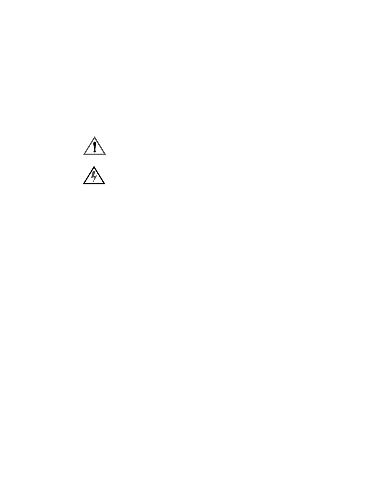
Safety symbols used throughout this manual are as follows:
FOREWORD
CAUTION advising of potential damage to product.
WARNING advising of potential injury or death to persons.
GENERAL INFORMATION PERTAINING TO PROTECTION AGAINST FIRE
AND ELECTRICAL SHOCK.
WARNING:
INSTRUCTIONS FOR CONTINUED PROTECTION AGAINST FIRE
1. Replace fuses with same type and rating only.
WARNING:
INSTRUCTIONS FOR CONTINUED PROTECTION AGAINST ELECTRICAL
SHOCK
1. VARI❋LITE® control consoles are designed for dry locations only. Exposure to rain or
moisture may damage the console.
2. Disconnect power before servicing any VARI❋LITE® equipment.
3. Servicing to be performed by qualified personnel only.
WARNING:
RF INTERFERENCE
1. This is a Class A product. In a domestic environment this product may cause radio
interference, in which case, the user may be required to take adequate measures.
02.9671.0010 C 24-March-2004 v

VARI❋LITE® - VL2000™ WASH LUMINAIRE SERVICE MANUAL
Sicherheitshinweise
Es ist äußerst wichtig, ALLE Sicherheitsinformationen und -hinweise in diesem
Handbuch und dem beiliegenden Informationsmaterial zu lesen, bevor Sie die hierin
beschriebenen Produkte installieren bzw. bedienen. Halten Sie bei der Installation und
dem Einsatz dieses Produkts alle Warnhinweise und Vorsichtsmaßnahmen ein.
Folgende Sicherheitssymbole werden in diesem Handbuch verwendet:
VORSICHT - weist auf möglichen Produktschaden hin.
WARNUNG - weist auf mögliche Körperverletzung und Leb-
ensbedrohung hin.
NACHSTEHEND FINDEN SIE ALLGEMEINE HINWEISE ÜBER SICHERHEITSVORKEHRUNGEN GEGEN FEUER UND ELEKTROSCHOCK.
WARNUNG:
HINWEISE ZUM FEUERSCHUTZ
1. Ersetzen Sie Sicherungen nur mit Sicherungen vom gleichen Typ und gleicher Stärke.
WARNUNG:
HINWEISE ZUM SCHUTZ GEGEN ELEKTROSCHOCK
1. VARI❋LITE®-Konsole eignen sich ausschließlich für trockene Standorte. Regen oder
Feuchtigkeit können die Konsole beschädigen.
2. Unterbrechen Sie die Stromzufuhr, bevor Sie mit der Arbeit an VARI❋LITE®-Geräten
beginnen.
3. Die Geräte sollten nur von qualifiziertem Personal gewartet werden.
WARNUNG:
HF-INTERFERENZ
1. Es handelt sich um ein Produkt der Klasse A. In einer Wohnumgebung kann das Produkt
Hochfrequenzstörungen verursachen. In diesem Fall müssen eventuell geeignete
Maßnahmen getroffen werden.
vi 24-March-2004 02.9671.0010 C

Notes de sécurité
Avant de procéder à l’installation des produits décrits dans ce guide et de les mettre en
marche, il est extrêmement important de lire TOUS les renseignements et TOUTES
les directives de sécurité contenues dans ce guide ainsi que toute documentation jointe.
Tenir compte de tous les avertissements et suivre toutes les précautions pendant
l’installation et l’utilisation de cet appareil.
Les symboles de sécurité utilisés dans ce guide sont les suivants :
FOREWORD
ATTENTION Ce symbole annonce que l’appareil risque
d’être endommagé.
AVERTISSEMENT Ce symbole annonce qu’il y a risque
d’accident grave ou même fatal.
CETTE SECTION CONTIENT DES INFORMATIONS GÉNÉRALES POUR SE
PROTÉGER CONTRE LES INCENDIES ET LES DÉCHARGES ÉLECTRIQUES :
AVERTISSEMENT:
DIRECTIVES POUR SE PROTÉGER CONTRE LES INCENDIES
1. Ne remplacer les fusibles qu’avec ceux du même type, ayant les mêmes caractéristiques.
AVERTISSEMENT:
DIRECTIVES POUR SE PROTÉGER CONTRE LES DÉCHARGES ÉLECTRIQUES
1. Les consoles de commande VARI❋LITE® sont conçues pour une utilisation au sec
uniquement. Une exposition à la pluie et à l’humidité risque d’endommager la console.
2. Débrancher l’appareil avant de procéder à la révision de tout matériel VARI❋LITE®.
3. Les révisions doivent être effectuées uniquement par des personnes qualifiées.
AVERTISSEMENT:
INTERFÉRENCE RF
1. Cet appareil est de Classe A. Dans un environnement domestique, cet appareil peut causer
des interférences radio, et si c’est le cas, l’utilisateur peut avoir à prendre des mesures
adéquates.
02.9671.0010 C 24-March-2004 vii
VARI❋LITE® - VL2000™ WASH LUMINAIRE SERVICE MANUAL
Aviso sobre Seguridad
Es muy importante leer TODA la información e instrucciones sobre seguridad que se
indica en este manual así como en los documentos adjuntos antes de instalar y operar
los productos descritos. Se debe prestar atención a todos los avisos y advertencias
durante la instalación y uso de este producto.
Los símbolos de seguridad usados en este manual son los siguientes:
CUIDADO, indica posibles daños al producto.
ADVERTENCIA, indica posibles lesiones o muerte a las
personas.
LA INFORMACIÓN GENERAL RELACIONADA A LA PROTECCIÓN CONTRA
INCENDIO Y GOLPES DE CORRIENTE ELÉCTRICA:
ADVERTENCIA:
INSTRUCCIONES PARA PROTECCIÓN CONTINUA CONTRA INCENDIO
1. Reemplaze los fusibles solamente con los del mismo tipo y especificación.
ADVERTENCIA:
INSTRUCCIONES PARA PROTECCIÓN CONTINUA CONTRA CHOQUE
ELÉCTRICO
1. Los controles de la consola de VARI❋LITE® están diseñados solamente para lugares
secos. La exposición a la lluvia o humedad pueden dañar la consola.
2. Desconecte la energía antes de dar servicio a cualquier equipo de VARI❋LITE®.
3. El servicio debe ser realizado solamente por personal calificado.
ADVERTENCIA:
INTERFERENCIA RF
1. Este es un producto de Clase A. En el ambiente de la casa este producto puede ocasionar
radiointerferencia, en cuyo caso, el usuario debe tomar las medidas adecuadas.
viii 24-March-2004 02.9671.0010 C

_KHæ2Ô0ç2Ä
Î
SAFETY NOTICE (JAPANESE)
ÎÎæ¿Ð
á¿~ÒÁ'
êùÕÄQ>X^Åî
ûéQ>X^é_KHæPÔ±ã[ÿ
ÚsÙæÄ~
îTæÐçÒáÞ:
Ä
Q>X^
âê
é_KQo"öª
ÌÚöªÔÙ
ТбКЫР¿
æêÔôáé0çPÄÅ
Òá¿ùÔ
0ç~æÊÍþH
6qP
õ
+4UV|¿æ»Ô é:´ÅîqP
ûNå±æß¿áê
:
6
+4é\¢ZËÚüé
1. VARI❋LITE®
3Ð
MSR575HR
Ìã¾âÔ
ÿzU
Jé+YæâýÌÎãЗвИщФf¦
ó
EXo-dµÔ'
ÒáÊÛп
4. VARI❋LITE®
Òá
ТбКЫР¿
ÿzUê
á¿ùÔ
åäÕÕzÔ
êÄQ>X^é0æåÞá2ÞÔ
ÿzUê»0°ùÚêé6.ÆÐåÛÌ
ÒáÊÛп
Ef;
\fJdµÔÙê
æßåǾH
é[ÿÅ\
Philips
ê+Ó
Åî
ÁæТбКЫР¿é³é\fJ
OsraméHID
EXo-Ô+Ó³+Ó
úÊÛп
\fJé³Ô
ÔôáÅ\úÊÛпù
ǽùÔ
ǽùÔ
ËÚüé
\fJöªÔ
MSR400
ÆÉäéÁå
æß¿áêÄQ>X^
"\,Õöª
Áæ
2
:
6
õZËÚüé
1. VARI❋LITE®
Ôâè²ÿ(Ç鿲æÌ
ǽùÔ
2. VARI❋LITE®
¿
ÿzUéCPêF,ßÛçéúÇÁÁæТбКЫР¿
02.9671.0010 C 24-March-2004 ix
Ef;
ÿzUêGÎ
ÿzUCPÔ'
ÒÚcºâöªÔ
Áæ
3Ð
ãÿzUÇÍ
êÕ5æ.¾
á¿ù
ûÎã
ЮбКЫР

VARI❋LITE® - VL2000™ WASH LUMINAIRE SERVICE MANUAL
c
~
Î
:
6
é
UV
|¿æÐÐå¿Úüé
Ef;
1. VARI❋LITE®
Òá¿ùÔ
_f-
ùÚê
*o^<¡"¹Y
ÇÊå
6
:
G2ZËÚüé
ÿzUÇP.
ÿ
&fPo@f;ÒÁÙæ꡾åUÔ»<ÿ;ªÜÕ
ª
ÒáÊÛп
ÿzUÇP.
ÿzUéÊêUV|¿¢Õ
\fJåÞÔ
*o^<ö
Îãê±ÌáÊÛп
ÕæÿzUP.Ôã¾âÔ
êíîÿÓ¿
ÁæåÞÚ§Ã
ÁæÒùÔ
Ef;
Òá¿ãÈêØé¥Ç²
Òá¿ãÈêØé
\fJDz
HID
ÞÆÈÍåäæ
2Jé\fJöª
Øé
ÊåùÔ²ÊåÞÚzU
ÊåùÔ
\fJdµ
Ô'êÿzUé.¾\fJé÷2ÇÇùâÙÞáÊÛ
п
¾
o".ê¡"|¿
áé;àОФОгЗ½ùÔÐæ
â6
âqPÿ+4Ç¢Ô¾0
cP.Ô
ÊÍ
\fJ
'
ÒÚ
\fJÒÁ'
é
ñÚ½Ì㤿
ǽùÔ
ÒùÔÎé¡"æÞáíä¿+Ív
ÒùÔØéÚüû
o".Ç_ÊÔ
ǽùÔ
ãÈæê;ªÜª
꡾åUÔ»<ÿ;ªÜÕª
,64ÇÛ
¿á
o".êö÷é)
ÒáÊÛп
\fJé.Ç
ãîÞÚ_
ÒáÊÛп
»<ªÖÕæå»â
\fJÈ
.I
ÍÇß¿Ú
¿æÒ{ÊÕé´å¿Óâ¿áÆÿzUÌ
ÁæÒùÔ
\fJÿ²æ
\fJÞÚ'
Þá»
ÒÚ
\fJê§
ê0
^&o^öÞá
ÃáÊÛп
_f-
2
ÞÚ
ö
:
6
RF
ä
1.
Ä
ê
Class A
ÎÔ»0ǽùÔØé'öª*꡾å
å¿ÎãǽùÔ
o".é0
1.
ß
ùÚê"Èåö
Ê(FÅÊÁжТбКЫР¿
,9S!oæ
½ùÔ
o".êP6.âÔ
x 24-March-2004 02.9671.0010 C
æ½Ð
ùÔ
:6Jßæ
Þáê÷2Ç
Ä~
ê8cº
o".cP.Ô'
æÅ¿áu"äà
£
åÌëå
êÒë
Lamp Power- Up State ÔL ON/ L OFF
Õ
ЗЮЪгИæ,GæcP.Ð'
*
ý

Table of Contents
Introduction
About This Manual ...................................................................................................... 1
Additional Documentation........................................................................................... 1
Customer Service......................................................................................................... 2
Technical Bulletins and Notices............................................................................ 2
Chapter 1. Description
Features
Standard Features......................................................................................................... 4
Major Components
VL2000 Wash Luminaire............................................................................................. 5
Menu Display............................................................................................................... 6
LED Indicators............................................................................................................. 6
Head Components........................................................................................................ 7
Yoke Components ........................................................................................................ 8
Enclosure Components ................................................................................................ 9
Principles of Operation
Power and Data Flow Diagrams ................................................................................ 10
TABLE OF CONTENTS
Chapter 2. Maintenance
Te st in g
Testing Software ........................................................................................................ 12
Special Considerations
Configuring Main Controller Board .......................................................................... 13
Jumper Configuration.......................................................................................... 14
Maintenance Procedures
Head Assembly.......................................................................................................... 15
Lamp Replacement.............................................................................................. 15
Align Lamp for Flat Field ................................................................................... 17
Color Bulkhead Assembly Replacement............................................................. 18
Color Filter Replacement .................................................................................... 20
Magenta Color Wheel Glass Assembly............................................................... 21
Crossfade Color Sensor PCB Assembly Replacement........................................ 22
Dimmer Bulkhead Assembly Replacement ........................................................ 23
Front Internal Head Assembly Replacement....................................................... 24
Blue/Amber Color Wheels Assembly Replacement ........................................... 25
Small Stipple Glass Replacement........................................................................ 27
Concave Lens Assembly Replacement ............................................................... 28
Convex Lens Assembly Replacement................................................................. 29
100MM Condenser Lens Assembly Replacement.............................................. 31
Beam Spreader Motor Assembly Replacement................................................... 33
Yoke Assembly .......................................................................................................... 35
02.9671.0010 C 24-March-2004 xi

VARI❋LITE® - VL2000™ WASH LUMINAIRE SERVICE MANUAL
Tilt Motor Replacement....................................................................................... 35
Auxiliary Controller PCB Assembly Replacement’............................................ 37
Ignitor PCB Assembly Replacement................................................................... 39
Enclosure Assembly................................................................................................... 41
Removing Enclosure Covers................................................................................ 41
Power Supply Replacement................................................................................. 43
Ballast Module Assembly Replacement.............................................................. 44
Pan Motor Assembly Replacement...................................................................... 46
Main Controller PCB Assembly Replacement.................................................... 48
DMX Input PCB Assembly Replacement ........................................................... 50
Cleaning Lens............................................................................................................. 51
Chapter 3. Illustrated Parts Breakdown
Drawing Tree
VL2000 Wash Luminaire (20.9671.0001).................................................................. 54
Top Ass emb ly
Included Items Kit...................................................................................................... 56
Top Ass emb ly
VL2000 Wash Luminaire ........................................................................................... 57
Head
Head Assembly........................................................................................................... 59
Front Internal Head Assembly.................................................................................... 61
Front Color Assembly ................................................................................................ 63
Blue/Amber Color Wheels Assembly........................................................................ 65
Amber Color Wheel Assembly .................................................................................. 66
Amber Color Wheel Pulley Assembly ....................................................................... 67
Blue Motor Assembly................................................................................................. 68
Amber Motor Assembly............................................................................................. 69
Front Lens Assembly.................................................................................................. 70
Convex Lens Assembly.............................................................................................. 71
Rear Assembly............................................................................................................ 72
Tilt Pulley/Bearing Assembly .................................................................................... 74
Tilt Bearing Housing Assembly ................................................................................. 75
Reflector Assembly .................................................................................................... 76
Back Cap Assembly ................................................................................................... 77
Fan Cover Assembly .................................................................................................. 79
Dimmer Bulkhead Assembly ..................................................................................... 81
Optical Sensor Assembly ........................................................................................... 83
Color Bulkhead Assembly.......................................................................................... 84
Color W/O Color Wheels Bulkhead Assembly.......................................................... 86
Color Motor Assembly............................................................................................... 87
Sensor PCB Assembly................................................................................................ 88
Magenta Motor Assembly.......................................................................................... 89
Crossfade Color Sensor PCB Assembly..................................................................... 90
Filter Wheel Assembly............................................................................................... 91
xii 24-March-2004 02.9671.0010 C

Chapter 4. Illustrated Parts Breakdown
Yo ke
Yoke Assembly .......................................................................................................... 93
Ignitor PCB Assembly............................................................................................... 95
Aux Controller PCB Assembly.................................................................................. 96
Enclosure
Upper Enclosure Assembly........................................................................................ 99
Connector Panel Assembly...................................................................................... 104
Main Controller 3-Phase PCB Assembly ................................................................ 105
DMX Input PCB Assembly ..................................................................................... 109
Pan Tube Assembly ................................................................................................. 110
Pan Motor Assembly................................................................................................ 112
Pan/Tilt Encoder PCB Assembly............................................................................. 114
700W Arc Power Supply Ballast Module................................................................ 115
700W Ballast Board PCB Assembly ....................................................................... 117
700W Ballast Rider Board PCB Assembly ............................................................. 120
Tilt Motor Assembly................................................................................................ 123
TABLE OF CONTENTS
Chapter 5. Illustrated Parts Breakdown
Cables
Ground Strap Cable Assembly................................................................................. 125
AC Input Pigtail (Euro) Cable Assembly ................................................................ 126
AC Input Link Cable Assembly............................................................................... 127
AC Input Splitter Cable Assembly .......................................................................... 128
LVS Chassis Ground Cable Assembly..................................................................... 129
Main To Aux/Data & Power Cable Assembly......................................................... 130
Pan/Tilt Control Cable Assembly ............................................................................ 131
Lamp Supply Control Cable Assembly ................................................................... 133
Chassis To Yoke Ground Cable Assembly .............................................................. 134
Lamp Supply OT/Not On Cable Assembly............................................................. 135
Data I/O Link Cable Assembly................................................................................ 136
DC Output Cable Assembly ..................................................................................... 137
Lamp Supply Harness Cable Assembly................................................................... 138
Motor Harness Cable Assembly .............................................................................. 139
Yoke to Head Ground Cable Assembly ................................................................... 141
Lamp Supply To Relay Cable Assembly ................................................................. 142
Ignitor To Relay Cable Assembly............................................................................ 143
Head OT Switch #2 Cable Assembly ...................................................................... 144
DC Output XPiQ Cable Assembly .......................................................................... 145
Appendix A. Technical Bulletins 147
VL2000 Wash Luminaire Technical Bulletin List ................................................... 147
VL2000 Wash Luminaire Wire Diagram (Sheet 1) ................................................. 149
VL2000 Wash Luminaire Wire Diagram (Sheet 2) ................................................. 150
400W/625W/700W Ballast Schematic .................................................................... 151
02.9671.0010 C 24-March-2004 xiii

VARI❋LITE® - VL2000™ WASH LUMINAIRE SERVICE MANUAL
Ballast Rider Schematic ........................................................................................... 153
Auxiliary Controller Schematic................................................................................ 154
Main Controller Schematic....................................................................................... 157
DMX Input Schematic.............................................................................................. 161
Ignitor Schematic...................................................................................................... 162
xiv 24-March-2004 02.9671.0010 C

Introduction
About This Manual
This manual provides descriptions, repair procedures, and illustrated parts breakdowns
for all configurations of the VL2000™ Wash Luminaire. The manual is intended for
use by Vari-Lite personnel and by Vari-Lite’s customers/clients.
WARNING: It is important to read ALL accompanying safety and installation
instructions to avoid damage to the product and potential injury to yourself or others.
This manual covers the following models:
INTRODUCTION
Model Part Number
VL2000 Wash Luminaire 20.9671.0001
Note: Performing maintenance procedures contained in this manual may void the
product warranty. Refer to the Vari-Lite, Inc. Limited Warranty card included in the
shipping package for this VARI❋LITE® product.
Additional Documentation
A support webpage for VL2000 series luminaires is available at www.vari-lite.com
(follow the Support link).
A users manual is available for installation and operation of the VL2000 wash
luminaire. This manual is available in both printed and electronic (PDF) formats.
■ VL2000™ Wash Luminaire Users Manual (02.9671.0001).
02.9671.0010 C 24-March-2004 1

VARI❋LITE® - VL2000™ WASH LUMINAIRE SERVICE MANUAL
Customer Service
Our Goal
At Vari-Lite, we are committed to providing you the highest quality in customer
service. Our comprehensive resources are available to help your business succeed and
ensure you get the full benefit of being a Vari-Lite customer. Whether your needs are
telephone/troubleshooting assistance, product training or technical service, our fulltime staff of experienced professionals are on-hand to provide support.
How to Reach Us
For assistance in your area, call the dealer from which your product(s) were
purchased.
or
Contact an Authorized Service Center.
or
Contact the Vari-Lite Customer Service Department, 9am - 6pm CST Monday through
Friday, at the following:
phone: 1-877-VARI-LITE (1-877-827-4548)
fax: 214.647.8038
email: customerservice@vari-lite.com
Additional Resources
For additional resources and documentation, please visit our website at:
www.vari-lite.com and follow the Support link.
Technical Bulletins and Notices
Technical bulletins concerning the latest changes to VARI
❋LITE equipment are issued
from the Dallas, Texas USA office. They are documentation supplements that contain
procedures for equipment upgrades, retrofits, and repairs not found in the existing
manuals. Operator technical bulletins are also issued to document changes in control
software. Technical bulletins are integrated into the appropriate equipment manuals as
those manuals are revised. Bulletins are categorized by assembly or subassembly, and
identified by a number such as V24-001 (VL24XX luminaire Technical Bulletin
number 1).
Technical notices are also issued from the Dallas, Texas USA office. They are nonprocedural documents that contain information regarding product support issues,
current equipment problems, software bugs, and documentation corrections. All
technical notices begin with the prefix TN and are numbered sequentially, such as TN138 (Tech Notice number 138).
2 24-March-2004 02.9671.0010 C

CHAPTER 1.
Description
This chapter provides an overview of luminaire features, components
and operations.
• Features
• Major Components
• Principles of Operation
SERVICE
02.9671.0010 C 24-March-2004 3

VARI❋LITE® - VL2000™ WASH LUMINAIRE SERVICE MANUAL
Features
Standard Features
The VL2000 wash luminaire features zoomable
beam spreader optics, CYM color mixing, a
separate fixed color wheel and a high
performance dimmer/strobe mechanism.
The VL2000 wash luminaire contains the
following standard features:
•DICHRO❋TUNE™ radial color changer
which employs enhanced dichroic color
filters to produce smooth, full spectrum color
crossfades. The mechanism allows
independent cyan, magenta and amber color
control.
• An internal mechanical douser which provides intensity control and strobing.
• An upper enclosure that houses the control electronics as well as a power factor
corrected arc power supply or an SCR dimmer appropriate to the particular lamp
source.
• Control by VARI❋LITE systems or a wide variety of DMX-512 consoles without
the need for additional interface equipment.
• Two easy-install truss hook brackets for versatile hanging configurations.
• 700W arc source.
• Zoomable beam spreader.
4 24-March-2004 02.9671.0010 C

Major Components
VL2000 Wash Luminaire
The following illustration shows the major luminaire components and controls.
DESCRIPTION : MAJOR COMPONENTS
1
Head Assembly
Upper Enclosure Assembly
Yoke Assembly
Removable Lamp Assembly
(to access lamp for replacement)
Truss Hook
Bracket Assembly
AC Input Cable
Beam Adjustment Controls
Vertica l
Input Panel Components
Product Label ID
Main Power Switch
AC Input Cable
Data In
02.9671.0010 C 24-March-2004 5
Power and Data
LED Indicators
Data Thru
Horizontal
Focus
Menu Display
Captive Knob
for lamp access
(does not adjust
beam)
VARI❋LITE® - VL2000™ WASH LUMINAIRE SERVICE MANUAL
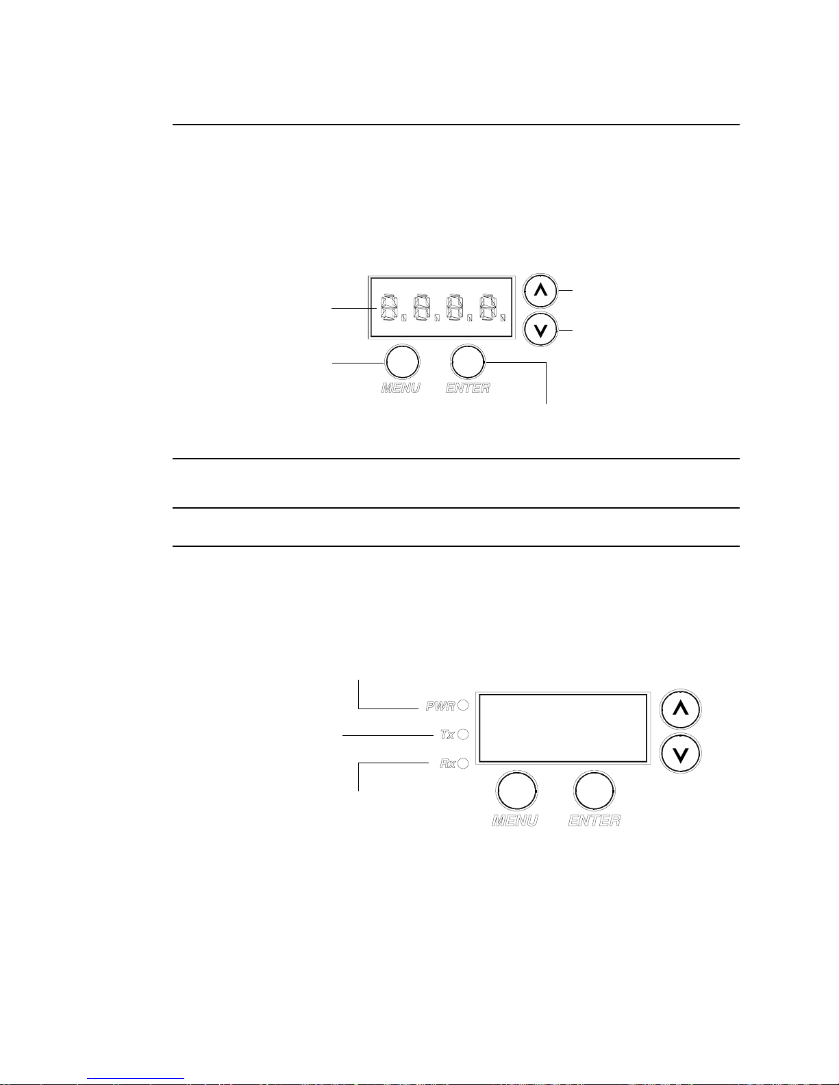
Menu Display
The Menu System Display is used to access the menu system, which is a
programmable set of commands used to address, operate, and test the luminaire.
The menu system is controlled by four buttons. These buttons function as follows:
Multi-Segment
Display
Displays the menu,
or if at first level, the
current address
Changes a value or
scrolls through menus
Changes a value or
scrolls through menus
Selects the current menu option
or enters current data value
Note: Refer to the VL2000 Wash Luminaire User’s Manual for more detailed
instructions regarding display operation.
LED Indicators
The LED indicators report the status of power and data to the luminaire.
Indicates DC power is being
supplied via AC Input when lit
Indicates data is being
transmitted when flashing
Indicates data is being
received when flashing fast;
when flashing in 2 sec. heartbeat,
indicates luminaire is idle
6 24-March-2004 02.9671.0010 C

DESCRIPTION : MAJOR COMPONENTS
1
Head Components
The following illustration shows the major sub-assemblies which are located in the
luminaire head assembly.
Dim
Dimmer Bulkhead Assembly
Color Bulkhead Assembly
Removable Cover
Rear Assembly
(Contains Lamp
Assembly)
Fan Assembly
Front Internal Assembly
(Contains lens assemblies and
front color assembly.)
02.9671.0010 C 24-March-2004 7
Nose Cover

VARI❋LITE® - VL2000™ WASH LUMINAIRE SERVICE MANUAL
Yoke Components
The following illustration shows the major sub-assemblies which are located in the
luminaire yoke assembly. (Head and enclosure not shown for clarity.)
Auxiliary Controller
PCB Assembly
Board-side Leg
Relay Assembly
Tilt-side Leg
Ignitor PCB Assembly
Tilt Motor
Assembly
Tilt-side
Yoke Leg
Rotate yoke fully
counter-clockwise
Input Panel Assembly
8 24-March-2004 02.9671.0010 C
Board-side Yoke Leg
To determine which yoke leg is which without having to remove
the covers, rotate yoke counterclockwise until it stops, then look
at the luminaire while facing the input panel assembly. The tiltside leg is the leg to the left; the board-side leg is the leg to the
right.

DESCRIPTION : MAJOR COMPONENTS
1
Enclosure Components
The following illustration shows the major sub-assemblies which are located in the
luminaire enclosure assembly. (Yoke and head assemblies not shown for clarity.)
Enclosure Covers
Ballast Module
Assembly
Power Supply
Input Panel Inside View
DMX Input PCB Assembly
Main Controller PCB
Main Controller
PCB Assembly
DMX Input
PCB Assembly
02.9671.0010 C 24-March-2004 9
Input Panel
Assembly
Enclosure Assembly

VARI❋LITE® - VL2000™ WASH LUMINAIRE SERVICE MANUAL
Principles of Operation
Power and Data Flow Diagrams
The following diagram shows how data and power are distributed in the luminaire.
DMX
INPUT
PCB
EMI
FILTER
PAN
MOTOR
CONTROL
PAN
ENCODER
PAN EOT
AC
ON/OFF
C.B.
CHASSIS
FAN
MAIN
PCB
TILT
MOTOR
TILT
ENCODER
TILT EOT
LOW
VOLTAGE
SUPPLY
AMBER
BLUE
HEAD
FAN
#1
AUX
CONTROL
PCB #2
BLUE/AMBER
SAFTEY
RELAY
NOT
USED
BEAM
DIMMER
MAGENTA
MAGENTA
HEAD
FAN
AUX
CONTROL
PCB #1
DIMMER
SENSOR
HEAD
OVERTEMP
SWITCH
#2
COLOR
NOT
USED
COLOR
SENSOR
BACK
CAP
SWITCH
10 24-March-2004 02.9671.0010 C
ARC
POWER
SUPPLY
IGNITOR
PCB
ARC
LAMP

CHAPTER 2.
Maintenance
This chapter contains test, service, and standard maintenance
procedures.
• Testing
• Special Considerations
• Maintenance Procedures
WARNING: All maintenance procedures are to be performed with
power removed from the luminaire. Never remove cover or backcap
while lamp is in operation.
SERVICE
02.9671.0010 C 24-March-2004 11

VARI❋LITE® - VL2000™ WASH LUMINAIRE SERVICE MANUAL
Testing
Testing Software
Testing software is available in all Series 2000 luminaires through the luminaire’s
menu system TEST function.
For information on specific tests and test parameters, see the VL2000 Wash Luminaire
User’s Manual (VL Part no. 02.9671.0001).
When running tests on multiple luminaires, a loopback connector is required at the
first luminaire in the link and a male termination connector is required at the last
luminaire.
Note: After 10 seconds of inactivity, the menu display will change to the default state
showing the address.
Move Disable
The Move option is available in the test menu. This allows for pan/tilt functions to be
disabled so that the luminaire can be placed in any position for testing without
movement occurring. In order to regain full control of the luminaire, Move will need
to be enabled after testing.
Note: When setting the Move option to disable, luminaires linked by a loopback
connector will have pan and tilt disabled for all the luminaires that are linked.
Lamp
The Lamp option is also available in the test menu. This option sets the lamp
intensity to 100% and will adjust the diffusion to produce a tight beam. Pan/Tilt are
disabled while using the Lamp option, and pan/tilt settings will be restored upon exit
of the Lamp feature.
Note: When setting the Lamp option on luminaires linked by a loopback connector,
pan and tilt will be disabled for all the luminaires that are linked.
To r un tests:
Step 1. Press [Menu].
Step 2. Press [Up] / [Down] arrows until TEST appears. Press [Enter].
Step 3. Use [Up] / [Down] arrows to select a parameter to test.
Step 4. Press [Enter] to run test.
Step 5. Press [Menu] to stop test at any time.
12 24-March-2004 02.9671.0010 C

Special Considerations
Configuring Main Controller Board
When performing maintenance or troubleshooting procedures on Series 2000
luminaires, it may be necessary to configure the Main Controller Board (MCB) for
installation. When moving an MCB from one luminaire another, different jumper
configurations must be set correctly in order for the luminaire to operate.
The Main Controller Board (MCB) contains two blue jumpers.
CAUTION: Always use anti-static precautions when working with PCBs.
Programming Jumper - J1 (For Vari-Lite engineering use.)
The jumper at J1 is necessary and must be in the correct position in order for the
luminaire to operate. DO NOT change the configuration of jumper J1 (Figure 2-1).
Jumper at J11
MAINTENANCE : SPECIAL CONSIDERATIONS
2
Power Supply
Connection
at J2
Jumper at J1
Figure 2-1: Jumper Locations on MCB
Luminaire Type Jumper - J11
The jumper at J11 configures the luminaire type between VL2000 spot, VL2000 wash
and VL2416 wash. For VL2000 spot or VL2416 wash luminaires, it is fitted to nonactive pins. (This inactive setting is the default or shipping configuration.) For
VL2000 wash luminaires, it is fitted to the active pins.
Power Supply Connection - J2
The power supply connection at J2 sets the luminaire type according to the power
supply output. (VL2416 wash luminaire - 1200W / VL2000 spot luminaire and
VL2000 wash luminaire - 700W). If the power selection setting and the luminaire type
setting jumper (J11) do not correspond, the luminaire will not operate properly.
02.9671.0010 C 24-March-2004 13

VARI❋LITE® - VL2000™ WASH LUMINAIRE SERVICE MANUAL
Jumper Configuration
To configure jumper:
Determine which type luminaire the MCB is to be installed in, and configure jumper
according to Figure 2-2.
Note: If luminaire will not calibrate or operate after MCB replacement, check jumper
setting and download new software.
VL2000 Spot,
and VL2416 Wash
Figure 2-2: MCB Jumper Configuration.
Main Controller Board
Component Side
PH3
J11
PH4
Jumper
VL2000 Wash
PH3
J11
PH4
14 24-March-2004 02.9671.0010 C

MAINTENANCE : MAINTENANCE PROCEDURES
Maintenance Procedures
Head Assembly
This section provides removal and replacement procedures for components found in
the luminaire head assembly.
Lamp Replacement
Parts:
LAMP, 700 WATT ARC - PHILLIPS MSR700 (71.2528.0700)
Tools:
#2 Phillips Screwdriver,
Cotton gloves
To remove and replace lamp:
2
WARNING: All maintenance procedures are to be performed with power removed
from the luminaire. Never remove covers or open front lens or backcap assemblies
while lamp is in operation.
Step 1. Disconnect luminaire AC input cable from power source.
WARNING: Allow lamp to cool before replacing.
Step 2. At backcap, using screwdriver or fingers, turn captive knob until loose
(Figure 2-3).
Head Assembly
Backcap Assembly
Lamp
Captive
Knob
02.9671.0010 C 24-March-2004 15
Guide Rod
Figure 2-3: Lamp Replacement

VARI❋LITE® - VL2000™ WASH LUMINAIRE SERVICE MANUAL
Step 3. Slide backcap away from head assembly (it will remain attached by tether).
CAUTION: Wear cotton gloves or other covering while servicing lamp. Touching
lamp glass with bare fingers will leave oil and cause the lamp to explode or burn out
early. If touched, use alcohol to thoroughly clean glass.
Step 4. Remove lamp by pulling straight out of socket.
Step 5. Install new lamp, pressing firmly into socket.
Step 6. Align guide rods in guide holes and slide backcap into head assembly. Re-
tighten captive knob.
Step 7. Align lamp. (Refer to next procedure.)
16 24-March-2004 02.9671.0010 C
 Loading...