

Page 1

VARI❋LITE® Control Systems
Virtuoso™ / Virtuoso™ DX
Console User’s Manual
SV 4.2
Express yourself.
Page 2

VARI❋LITE® - VIRTUOSO™ / VIRTUOSO™ DX CONSOLE USER’S MANUAL
VAR I❋LITE
®
, Artisan®, mini-Artisan®, mini-Artisan
®
2, Artisan®Plus, mini-Artisan®Plus, VL2
®
, and VLD® are
trademarks owned by Vari-Lite, Inc., 201 Regal Row, Dallas TX 75247 USA. and are registered in the United State s and other
countries.
VL1000™, VL2000™, VL2201™, VL2202™, VL2400™ (and the individual product designations), VL3000™, Virtuoso™,
™
Virtuoso™ DX, VA RI ❋LITE Visionary
™
VL6B
, VL6C™, VL7™, VL7B™, VLM™, APS6™, C3™, ArtisanVLQ™, SPC-36™, UDM™, AutoTruss™, SmartDMX™,
Smart Repeater
DICHRO❋TUNE
™
, Series 100™, Series 200™, Series 300™, Series 2000™, Series 3000™, DICHRO❋WHEEL™,
™
, VACU❋DEP™, VARI❋IMAGE™, VARI❋BEAM™, and the Vari-Lite Asterisk are also trademarks
, VL1™, VL2B™, VL2C™, VL3™, VL4™, VL5™, VL5Arc™, VL5B™, VL6™,
owned by Vari-Lite, Inc.
VAR I❋LITE® products are protected by one or more of the following patents, and other pending patent applications worldwide:
U. S. Patents No. 6,123,436; 6,113,252; 6,046,861; 6,031,749; 6,011,640; 5,969,868; 5,959,768; 5,934,794; 5,882,107; 5,829,868;
5,825,548; 5,798,619; 5,7 74, 273; 5,769,527; 5,758,956; 5,7 28, 994; 5,640,061; 5,590,954; 5,4 54, 477; 5,432,691; 5,367,444;
5,329,431; 5,307,295; 5,2 82, 121; 5,278,742; 5,209,560; 5,1 86, 536; 5,073,847; 5,010,459; 4,9 80, 806; 4,972,306; 4,800,474;
4,779,176; 4,701,833; 4,6 02, 321;
U. S. Design Patents No. 439,356; 420,3 32; 417, 300; 415,301; 413,995; 377,3 38; 366, 712; 359,574; 350,408; 347,113;
Australia Patents No. 693,691; 683, 695; 667,109; 649,264; 646,5 88; 586, 095; 576,400; 546,433;
Australia Design Patents No. 128,796; 128 ,7 95;
Canada Patents No. 2,070,670; 2,050,375; 1,270,675; 1,259,058; 1,181,795;
Canada Design Patents No. 81,234; 81 ,2 33; 76, 046;
European (UK) Patents No. 0 652 400; 0 586 049; 0 565 218; 0 547 732; 0 534 710; 0 495 305; 0 474 202; 0 379 970; 0 253 082;
0 253 081; 0 248 974; 0 192 882; 0 140 994; 0 060 068;
Germany Patents No. 694 25 943.8; 693 14 122.0; 692 08 615.3; 692 07 692.1; 691 31 478.0; 691 21 029.2; 690 33 385.4; 37 89
166.9; 37 68 727.1; 37 51 804.6; 37 50 201.8; 35 87 270.5; 32 79 888.1; 32 74 291.6;
Germany Design Patents No. M 98 01 745.4; M 96 04 515.9; M 96 04 514.0; M 94 07 689.8; M 94 02 951.2; M 499 03 583.6; M
498 11 203.9; G 93 12 884.3;
Spain Patents No. 2 090 191; 2 084 289; 2 020 96 0; 0 548 328;
Spain Utility Model Patent No. 2.031. 74 8;
Spain Design Patents No. 0.137.502; 0.1 37.501; 0.133.573;
Greece Patent No. 910.400.544;
Hong Kong Patents No. 965/1990; 28 5/ 1987;
Japan Patents No. 2,843,696; 2,059,669; 2,055,324; 2,002,168; 1,966,525; 1,889,481; 1,7 92, 721; 1,770,241; 1,723,825;
1,683,007; 1,533,011;
Japan Design Patents No. 985,985-1; 985,985; 947,552; 945,436 -1; 945,436; 1,106,089; 1,07 7, 598; 1, 072,598; 1,060,414;
1,002,123;
Korea Patents No. 76,310; 42,639; 28 3, 770; 181,180;
Korea Design Patents No. 209,896; 209,895;
Mexico Patent No. 180,148;
Singapore Patents No. 663/90; 134/8 7;
Taiwan Patents No. 78,726; 66,975; 65,380; 28,275;
United Kingdom Design Regi stra ti ons N o. 2082526; 2072562; 2056387 ; 20 56386; 2042174; 2038212; 2033108; 2029499.
Apple®, Macintosh®, and FireWire® are registered trademarks of Apple Computer, Inc.
Zip® is a registered trademark of Iomega® Corporation.
All other brand or product na m es wh i ch ma y be mentioned in this manual are trademarks or registered trademarks of their
respective companies or organizations.
Virtuoso™ / V irtuoso™ DX Console User’s Manual
The informa tion furnis h ed in this man ual is for info r mational use only and is subject to change without notice. Vari-Lite, Inc.
assumes no responsibility or liabi lity for any errors or inaccura ci es that may appear in this manual. All information an d gra phic
representations are property of Vari-Lite, Inc. 201 Regal Row, Dallas, Texas 75247 USA.
Version as of: 23-Sep-02
Printed in th e USA.
Part number: 02.9651.000 1 C
Virtuoso™ / Virtuoso™ DX Console User ’s Manual
© 2001-2002 Vari-Lite, Inc. All Rights Reserved.
ii 23-Sep-02 02.9651.0001 C
Page 3

VARI❋LITE® - VIRTUOSO™ / VIRTUOSO™ DX CONSOLE USER’S MANUAL
End User Software License
PLEASE READ THIS DOCUMENT CAREFULLY BEFORE ACTIVATING, COPYING, INSTALLING,
OR USING THIS SOFTWARE PROVIDED BY VARI-LITE, INC. BY ACTIVATING, COPYING,
INSTALLING, OR USING THIS SOFTWARE, YOU ARE AGREEING TO BE BOUND BY THE TERMS
OF THIS LICENSE. IF YOU DO NOT AGREE TO THE TERMS OF THIS LICENSE, DO NOT ACTIVATE, COPY, INSTALL, OR USE THIS SOFTWARE AND PROMPTLY RETURN IT FOR A REFUND.
Virtuoso™ DX software and related documentation (collectively, the “Software”) solely with the Virtuoso DX
1. License
console sold in conjunction with the Software. Vari-Lite retains all right, title and interest to the Software which
is protected by var ious proprietary rights, including but not limited t o copyrights, tra de secrets, or patents
("Proprietary Rights"). No lice nse, right or interest in any trademark, trade name or service mark of Vari-Lite or
any third party is granted under thi s License.
2. No Implied License. You acknowledge that this License in no way shall be construed to provide an
implied license to use, modify or improve any of Vari-Lite’s patented technology, copyrights, trade secrets,
trademarks, and/or other Proprietary Right s.
3. Restrictions. T he Software contains pr oprietary information that is possibly pr otected by a
combination of patent, copyright, trade secret, and/or other Proprietary Rights, and constitutes valuable property of
Vari-Lite. You acknowledge that the Software is disclosed in circumstances of confidence and only for use by you
under the terms and conditions of this License and that you do not acquire any rights of ownership or title in the
Software. You may not attempt to create or derive source codes by disassembly, reverse engineering or any other
method, or otherwise reduce the Software to a human-perceivable form. You may not modify or translate any part
of the Software . You may not use, disclose, distribute, make or have made a ny copie s of the So ft w ar e, in wh ol e or
in part, without the prior written authorization of Vari-Lite. You agree to make reasonable efforts to notify and
inform your employees or agents having access to the Software of your limitations, duties and obligations regarding
non-disclosure and copying of the Software. The Software shall be used only by you, your employees or your
authorized agents. You agree to provide notice to Vari-Lite immediately after learning of or having reason t o
suspect a breach of any of the restrictions set forth in this License.
4. Termination. This License is effective until terminated. You may terminate this License at any time
by destroying the Software, and all copies thereof. This License will terminate immediately without notice from
Vari-Lite if you fail to comply with any provision of this License. Upon termination, you must destroy the
Software and all copies thereof.
5. Export Control Requirements. This License, and any technical information supp lied during the term of
this License, is made subject to any restrictio ns concern ing the expo rt of prod ucts or techni cal data from the United
States of America whi ch may b e imp osed upon Vari-Lite or yo u from time to time by the Governm ent of th e United
States of America. Furthermore, you agree that at no time, either during the term of this License or thereafter, will
you knowingly export, directly or indirectly, any United States source technical data acquired from Vari-Lite under
this License or any direct products of that technical data to any country for which the U.S. Government or any
agency thereof at the time of export requires an export license or other governmental approval, without first
obtaining that license or approval when required by applicable United States law.
. Vari-Lite, Inc. (“Vari-Lite”) hereby grants you a limited license to install and use the
defects in materials and workmanship unde r normal use for a period of ninety (90) days fr om the date of purchase
as evidenced by a copy of your receipt. Vari-Lite’s entire liabili ty an d yo ur exc lusiv e remed y will be replace m ent
of a media that does not meet Vari-Lite’s limited warranty and is returned at your expense, along with a copy of
your receipt, to Vari-Lite customer support or to Vari-Lite’s authorized representative. If replacement of the media
is not reasonably practical or commercially rea son able a s d et ermin ed sole ly in th e discretion of Vari-Lite, Vari-Lite
will refund the purchase price as evidenced by a purchase receipt. Vari-Lite will have no responsibility to replace
media damaged by accident, abuse or misappl ication. EXCEPT FOR THE FOREGOING, THE SOFTWARE
AND RELATED DOCUMENTATION ARE PROVIDED "AS IS," WITHOUT ADDITIONAL
WARRANTY OF ANY KIND, AND VARI-LITE EXPRESSLY DISCLAIMS ALL OTHER
WARRANTIES, EXPRESS OR IMPLIED, INCLUDING, BUT NOT LIMITED TO, THE IMPLIED
WARRANTIES OF DESIGN, MERCHANTABILITY, FITNESS FOR A PARTICULAR PURPOSE, OR
TITLE, ANY WARRANTIES ARISING FROM A COURSE OF DEALING, USAGE, OR TRADE
PRACTICE, OR ANY WARRANTIES OF NON-INFRINGEMENT OF ANY THIRD PARTY'S
P ATENT(S), TRADE SECRET(S), COPYRIGHT(S) OR OTHER INTELLECTUAL PROPERTY
RIGHTS. VARI-LITE DOES NOT WARRANT THAT THE FUNCTIONS CONTAINED IN THE
SOFTWARE WILL MEET YOUR REQUIREMENTS, OR THAT THE OPERATION OF THE
SOFTWARE WILL BE UNINTERRUPTED OR ERROR-FREE, OR THAT DEFECTS IN THE
SOFTWARE WILL BE CORRECTED. FURTHER MORE, VARI-LITE DOES NOT WARRANT OR
MAKE ANY REPRESENTATIONS REGARDING THE USE OR THE RESULTS OF THE USE OF THE
SOFTWARE OR RELATED DOCUMENTATION IN TERMS OF THEIR CORRECTNESS,
ACCURACY, RELIABILITY, OR OTHERWISE. NO ORAL OR WRITTEN INFORMATION OR
02.9651.0001 C 23-Sep-02 iii
6. Limited Warranty. Vari-Lite warrants the media on which the Software is recorded to be free from
Page 4

VARI❋LITE® - VIRTUOSO™ / VIRTUOSO™ DX CONSOLE USER’S MANUAL
ADVICE GIVEN BY VARI-LITE OR ITS AUTHORIZED REPRESENTATIVE SHALL CREATE ANY
WARRANTY OR IN ANY WAY INCREASE THE SCOPE OF THIS WARRANTY. SHOULD THE
SOFTWARE PROVE DEFECTIVE, YOU (AND NOT VARI-LITE OR ITS AUTHORIZED
REPRESENTATIVE) ASSUME THE ENTIRE COST OF ALL NECESSARY SERVICING, REPAIR OR
CORRECTION. SOME STATES DO NOT ALLOW EXCLUSION OF IMPLIED WARRANTIES, SO
THE ABOVE EXCLUSION MAY NOT APPLY TO YOU. THIS WARRANTY GIVES YOU SPECIFIC
LEGAL RIGHTS, AND YOU MAY ALSO HAVE OTHER RIGHTS WHICH VARY FROM STATE TO
STATE.
SHALL VARI-LITE BE LIABLE FOR ANY LOST REVENUE OR PROFITS OR ANY INCIDENTAL,
7. Limitation Of Liability
INDIRECT, SPECIAL, OR CONSEQUENTIAL DAMAGES THAT RESULT FROM THE USE OR
INABILITY TO USE THE SOFTWARE OR RELATED DOCUMENTATION, EVEN IF VARI-LITE OR
ITS AUTHORIZED REPRESENTATIVE HAS BEEN ADVISED OF THE POSSIBILITY OF SUCH
DAMAGES. SOME STATES DO NOT ALLOW THE LIMITATION OR EXCLUSION OF LIABILITY
FOR INCIDENTAL OR CONSEQUENTIAL DAMAGES SO THE ABOVE LIMITATION OR
EXCLUSION MAY NOT APPLY TO YOU. IN NO EVENT SHALL VARI-LITE’S TOTAL LIABILITY
TO YOU FOR ALL DAMAGES, LOSSES, AND CAUSES OF ACTION, WHETHER IN CONTRACT,
TORT (INCLUDING NEGLIGENCE) OR OTHERWISE, EXCEED THE AMOUNT PAID BY YOU FOR
THE SOFTWARE.
8. Arbitration, Jurisdiction, and Venue
License or relating to this Software shall be resolved, individually, through biding arbitration usin g th e th e n cu rrent
rules of the American Arbitration Association, in Dallas, Texas and the resulting decisions may be entered in any
court with proper juri sdiction. This mea ns that if y ou hav e a grie vance with us, yo u cann ot take us to c ourt, and yo u
may not join your action with any other party. You can address such grievances through arbitration only and you
are hereby consenting to do it in Dallas, Texas, using Texas' laws (without regard to Texas' conflicts of laws). You
agree that are properly subject to the jurisdiction of the courts of the State of Texas and waive any rights to
challenge personal jurisdict io n.
9. Government Licensee. If you are acquiring the Software on behalf of any unit or agency of the United
States Government, the following provisions appl y: (a) the Governme nt ack nowle dg es Vari-Lite’s representation
that the Software and its docume ntation were developed at private expense and no part of them is in the public
domain; (b) the Government acknowledges Vari-Lite’s representation that the Software is "Restricted Computer
Software" as that term is defined in Clause 52.227-19 of the Federal Acquisition Regulations ("FAR") and is
"Commercial Computer Software" as that term is defined in Subpart 227.471 of the Department of Defense Federal
Acquisition Regulation S upplement ("DFARS"). The Government agrees that: (i) if the So ftware is suppl ied to t he
Department of Defense ("DoD"), the Software is classified as "Commercial Computer Software" and the
Government is acquiring only "limited rights" in the Software and its documentation as that term is defined in
Clause 252.227-7013(a)(13) of the DFARS, and (ii) if the Software is supplied to any unit or agency of the United
States Government other than DoD, the Government’s rights in the Software and its documentation will be as
defined in Clause 52 .227-19(c)(2) of the FAR.
. UNDER NO CIRCUMSTANCES, INCLUDING NEGLIGENCE,
. You agree that any action at law or in equity arising out of the
affiliates, officers, directors, shareholders, employees and agents, from and against any costs, losses, liabilities and
expenses, including reasonable attorney’s fees, that Vari-Lite may suffer, incur, or be subjected to by reason of any
claim by a third party due to or arising out of your conduct, your use of the Sof tware, any allege d breach of this
License or the repr esentations an d warranties herein, the alleged violation of the rights of any third party, or any
alleged infringement of the intellectual property rights of any third party, including but not limited to your use of
any content, trademarks, service marks, trade names or other intellectual property used in connection wi th the
Software. Vari-Lite reserves the right to control the exclusive defense of any matter otherwise subject to your
indemnification, which will not excuse your indemnity obligations.
to the use of the Software and supersedes all prior or contemporaneous understandings or agreements, written or
oral, regarding such subject matter.
unenforceable, then that provision shall be deemed severabl e (or reformable, if necessary), and shall not affect the
validity and enforceability of any remaining provisions. Alternatively, such provision may also be modified to the
extent necessary for its validity.
13.Transfer. This License may be transferred to another party provided the other party reads and agrees to accept
the terms and conditions of this License and you notify Vari-Lite of the transfer in writing.
iv 23-Sep-02 02.9651.0001 C
10. Indemnity. You agree to indemnify and hold harmless Vari-Lite, and its parents, subsidiaries,
11. Complete Agreement. This License constitutes the entire agreemen t be twee n t he parti es wit h respec t
12. Miscellaneous. If any provision of this License sha ll be unlawful, void, or for any reason
Page 5

VARI❋LITE® - VIRTUOSO™ / VIRTUOSO™ DX CONSOLE USER’S MANUAL
How To Obtain Warranty Service
A copy of the Vari-Lite, Inc. Limited Warranty was included in the shipping package for this
VARI ❋LITE® product.
To obtain warranty service, please contact customer service at 1-877-VARI-LITE
(1-877-827-4548) or cus tomerserv ice@vlint .com and request a Ret urn Material Authorizat ion
(RMA) for warranty service. You need to provide the model and serial number of the item
being returned, a description of the problem or failure and the name of the registered user or
organization. If available, you should have your sales invoice to establish the date of sale as
the beginning of the warranty period.
Once you obtain the RMA, pack the product in its origina l packi ng material al ong with a copy
of your invoice (if available) and write the RMA number legibly on or near the shipping
address label. Return the unit, freight prepaid to:
Vari-Lite, Inc.
201 Regal Row
Dallas, TX 75247
Attention: Warranty Service
As stated in the warranty, it is require d that the shipment be insured and FOB our service
center.
02.9651.0001 C 23-Sep-02 v
Page 6

VARI❋LITE® - VIRTUOSO™ / VIRTUOSO™ DX CONSOLE USER’S MANUAL
Compliance Notice
FCC
This equipment has been tested and found to comply with the limits for a Class A
digital device pursuant to Part 15 of FCC Rules. These limits are designed to provide
reasonable protection against harmful interference when this equipment is operated in
a commercial environment. This equipment generates, uses, and can radiate radio
frequency energy and, if not installed and used in accordance with Vari-Lite system,
service, and safety guidelines, may cause harmful interference to radio
communications. Operation of this equipment in a residential area is likely to cause
harmful interference, in which case th e user will be required to correct the interference
at his/her own expense.
Declaration of Conformity
We declare, under our sole responsibility, that this product complies with the relevant
clauses of the following standards and harmonized documents:
Safety
EN 60950: 1999 Safety Standard for Information Technology Equipment
EMC
EN55022A: 1998 Radiated and Conducted Emissions
EN50082-1: 1997 Generic Immunity Standard
We certify that VARI❋LITE products conform to the protection requirements of
European council directives: 73/23/EEC (LVD) and 89/336/EEC (EMC)
vi 23-Sep-02 02.9651.0001 C
Page 7

Safety Notice
It is extremely important to read ALL safety information and instructions provided in
this manual and any accompanying documentation before installing and operating the
products described herein. Heed all cautions and warnings during installation and use
of this product.
Safety symbols used throughout this manual are as follows:
VARI❋LITE® - VIRTUOSO™ / VIRTUOSO™ DX CONSOLE USER’S MANUAL
CAUTION advising of potential damage to product.
WARNING advising of potential injury or death to persons.
GENERAL INFORMATION PERTAINING TO PROTECTION AGAINST FIRE
AND ELECTRICAL SHOCK.
WARNING:
INSTRUCTIONS FOR CONTINUED PROTECTION AGAINST FIRE
1. Replace fuses with same type and rating only.
WARNING:
INSTRUCTIONS FOR CONTINUED PROTECTION AGAINST ELECTRICAL
SHOCK
1. VARI❋LITE® control consoles are designed for dry locations only. Exposure to
rain or moisture may damage the console.
2. Disconnect power before servicing any VARI❋LITE® equipment.
3. Servicing to be performed by qualified personnel only.
WARNING:
RF INTERFERENCE
1. This is a Class A product. In a domestic environment this product may cause radio
interference, in which case, the user may be required to take adequate measures.
02.9651.0001 C 23-Sep-02 vii
Page 8

VARI❋LITE® - VIRTUOSO™ / VIRTUOSO™ DX CONSOLE USER’S MANUAL
Sicherheitshinweise
Es ist äußerst wichtig, ALLE Sicherheitsinformationen und -hinweise in diesem
Handbuch und dem beiliegenden Informationsmaterial zu lesen, bevor Sie die hierin
beschriebenen Produkte installieren bzw. bedienen. Halten Sie bei der Installation und
dem Einsatz dieses Produkts alle Warnhinweise und Vorsichtsmaßnahmen ein.
Folgende Sicherheitssymbole werden in diesem Handbuch verwendet:
VORSICHT - weist auf möglichen Produktschaden hin.
WARNUNG - weist auf mögliche Körperverletzung und Lebens-
bedrohung hin.
NACHSTEHEND FINDEN SIE ALLGEMEINE HINWEISE ÜBER
SICHERHEITSVORKEHRUNGEN GEGEN FEUER UND ELEKTROSCHOCK.
WARNUNG:
HINWEISE ZUM FEUERSCHUTZ
1. Ersetzen Sie Sicherungen nur mit Sicherungen vom gleichen Typ und gleicher
Stärke.
WARNUNG:
HINWEISE ZUM SCHUTZ GEGEN ELEKTROSCHOCK
1. VARI❋LITE®-Konsole eignen sich ausschließlich für trockene Standorte. Regen
oder Feuchtigkeit können die Konsole beschädigen.
2. Unterbrechen Sie die Stromzufuhr, bevor Sie mit der Arbeit an VARI❋LITE®-
Geräten beginnen.
3. Die Geräte sollten nur von qualifiziertem Personal gewartet werden.
WARNUNG:
HF-INTERFERENZ
1. Es handelt sich um ein Produkt der Klasse A. In einer Wohnumgebung kann das
Produkt Hochfrequenzstörungen verursachen. In diesem Fall müssen eventuell
geeignete Maßnahmen getroffen werden.
viii 23-Sep-02 02.9651.0001 C
Page 9

Notes de sécurité
A vant de procéder à l’installation des produits décrits dans ce guide et de les mettre en
marche, il est extrêmement important de lire TOUS les renseignements et TOUTES
les directives de sécurité contenues dans ce guide ainsi que toute documentation jointe.
Tenir compte de tous les avertissements et suivre toutes les précautions pendant
l’installation et l’utilisation de cet appareil.
Les symboles de sécurité utilisés dans ce guide sont les suivants :
VARI❋LITE® - VIRTUOSO™ / VIRTUOSO™ DX CONSOLE USER’S MANUAL
ATTENTION Ce symbole annonce que l’appareil risque d’être
endommagé.
AVERTISSEMENT Ce symbole annonce qu’il y a risque d’accident grave ou même fatal.
CETTE SECTION CONTIENT DES INFORMATIONS GÉNÉRALES POUR SE
PROTÉGER CONTRE LES INCENDIES ET LES DÉCHARGES ÉLECTRIQUES :
AVERTISSEMENT:
DIRECTIVES POUR SE PROTÉGER CONTRE LES INCENDIES
1. Ne remplacer les fusibles qu’avec ceux du même type, ayant les mêmes
caractéristiques.
AVERTISSEMENT:
DIRECTIVES POUR SE PROTÉGER CONTRE LES DÉCHARGES ÉLECTRIQUES
1. Les consoles de commande VARI❋LITE® sont conçues pour une utilisation au
sec uniquement. Une exposition à la pluie et à l’humidité risque d’endommager la
console.
2. Débrancher l’appareil avant de procéder à la révision de tout matériel
VARI❋LITE®.
3. Les révisions doivent être effectuées uniquement par des personnes qualifiées.
AVERTISSEMENT:
INTERFÉRENCE RF
1. Cet appareil est de Classe A. Dans un environnement domestique, cet appareil
peut causer des interférences radio, et si c’est le cas, l’utilisateur peut avoir à
prendre des mesures adéquates.
02.9651.0001 C 23-Sep-02 ix
Page 10

VARI❋LITE® - VIRTUOSO™ / VIRTUOSO™ DX CONSOLE USER’S MANUAL
Aviso sobre Seguridad
Es muy importante leer TODA la información e instrucciones sobre seguridad que se
indica en este manual así como en los documentos adjuntos antes de instalar y operar
los productos descritos. Se debe prestar atención a todos los avisos y advertencias
durante la instalación y uso de este producto.
Los símbolos de seguridad usados en este manual son los siguientes:
CUIDADO, indica posibles daños al producto.
ADVERTENCIA, indica posibles lesiones o muerte a las perso-
nas.
LA INFORMACIÓN GENERAL RELACIONADA A LA PROTECCIÓN CONTRA
INCENDIO Y GOLPES DE CORRIENTE ELÉCTRICA:
ADVERTENCIA:
INSTRUCCIONES PARA PROTECCIÓN CONTINUA CONTRA INCENDIO
1. Reemplaze los fusibles solamente con los del mismo tipo y especificación.
ADVERTENCIA:
INSTRUCCIONES PARA PROTECCIÓN CONTINUA CONTRA CHOQUE
ELÉCTRICO
1. Los controles de la consola de VARI❋LITE® están diseñados solamente para
lugares secos. La exposición a la lluvia o humedad pueden dañar la consola.
2. Desconecte la energía antes de dar servicio a cualquier equipo de VARI❋LITE®.
3. El servicio debe ser realizado solamente por personal calificado.
ADVERTENCIA:
INTERFERENCIA RF
1. Este es un producto de Clase A. En el ambiente de la casa este producto puede
ocasionar radiointerferencia, en cuyo caso, el usuario debe tomar las medidas
adecuadas.
x 23-Sep-02 02.9651.0001 C
Page 11

安全性に関する注意事項
安全性に関する注意事項
安全性に関する注意事項安全性に関する注意事項
ここに記載されている製品を取り扱う場合は、まず本マニュアルおよび付属
のマニュアルの安全性に関する情報と説明をすべてお読みください。また、
実際に本製品を取り付けたり使用する際には、すべての注意事項および警告
に留意して作業してください。
本マニュアルでは、以下の安全マークを使用しています。
注意
注意 : 製品に損傷を与える危険性があります。
注意注意
警告
警告 : 人身事故につながる危険性があります。
警告警告
火災防止および感電防止についての一般的な注意事項
警告
警告 :
警告警告
火災の発生を防ぐためのヒント
火災の発生を防ぐためのヒント
火災の発生を防ぐためのヒント火災の発生を防ぐためのヒント
1. ヒューズを交換する場合は、同じヒューズ(同じ種類、同じクラス)を使用して
ください。
警告
警告 :
警告警告
感電を防ぐためのヒント
感電を防ぐためのヒント
感電を防ぐためのヒント感電を防ぐためのヒント
1. VARI❋LITE® 制御装置は、乾燥した環境で使用するように設計されています。
雨で濡れる場所や湿気の多い場所に取り付けると、制御装置が傷むことがありま
す。
2. VARI❋LITE® 照明器具を修理点検する場合は、必ず先に電源を切ってください。
3. 照明器具の修理点検は、資格を持つ技師のみが行うようにしてください。
警告
警告 :
警告警告
RF 干渉
干渉
干渉干渉
1. 本製品は Class A に分類されます。本製品は、家庭環境において無線干渉を起こ
す可能性があります。その場合、使用者は適切な処置を取らなければならないこ
とがあります。
02.9651.0001 C 23-Sep-02 xi
Page 12

VARI❋LITE® - VIRTUOSO™ / VIRTUOSO™ DX CONSOLE USER’S MANUAL
(This page intentionally blank.)
xii 23-Sep-02 02.9651.0001 C
Page 13

Table of Contents
Introduction
About This Manual............................................................................................................. 1
Additional Documentation.................................................................................................. 1
Customer Service................................................................................................................ 2
Obtaining Additional DMX Profiles................................................................................... 2
Text Conventions ................................................................................................................ 3
Chapter 1. Descriptions and Overview
Virtuoso Console
Features............................................................................................................................... 6
Components ........................................................................................................................ 7
Console......................................................................................................................... 7
Network Interface (NIF) Unit....................................................................................... 7
Virtuoso DX Console
Features............................................................................................................................... 8
Components ........................................................................................................................ 9
Console......................................................................................................................... 9
Macintosh Computer.................................................................................................... 9
Virtuoso DX Console Accessories List............................................................................. 10
Operation Overview
Virtuoso Application......................................................................................................... 11
Window Interaction........................................................................................................... 11
Menus and Button Bar................................................................................................ 11
Entering/Editing Window Data.................................................................................. 12
Closing Windows....................................................................................................... 12
Locating Hidden Windows......................................................................................... 12
Status Indicator Bar........................................................................................................... 13
Arrange Monitors.............................................................................................................. 14
TABLE OF CONTENTS
Chapter 2. Installation
Virtuoso Console
Overview........................................................................................................................... 16
Unpacking Console Road Case......................................................................................... 16
Installing Desk Lamps...................................................................................................... 18
Pull-Out Keyboard Backlighting Adjustment................................................................... 18
Connecting Optional Components.................................................................................... 19
Connecting To System ...................................................................................................... 20
02.9651.0001 C 23-Sep-02 xiii
Page 14

VARI❋LITE® - VIRTUOSO™ / VIRTUOSO™ DX CONSOLE USER’S MANUAL
Virtuoso DX Console
Overview .......................................................................................................................... 21
Connecting Console & Computer Components ............................................................... 21
Keyboard Lock/Unlock.................................................................................................... 22
Installing Desk Lamps...................................................................................................... 23
Connecting Additional Components................................................................................ 24
Chapter 3. Power-Up and Patch
Power Up - DMX Systems (Virtuoso DX Only)
Powering Up Console....................................................................................................... 26
Powering Down Console.................................................................................................. 26
System Configuration Window........................................................................................ 27
❋
Power Up - VARI
Powering Up Console and NIF Units............................................................................... 28
Powering Down Console.................................................................................................. 28
System Configuration Window........................................................................................ 29
Console Naming......................................................................................................... 30
Store Configuration.................................................................................................... 31
Update Configuration................................................................................................. 31
Patch
Overview .......................................................................................................................... 32
Setting Up Plan View Window......................................................................................... 33
Plan View Background Picture.................................................................................. 34
Patching DMX/Conventional Fixtures............................................................................. 35
Patching VARI❋LITE Series 300 Luminaires................................................................. 40
Dimmer Curves ................................................................................................................ 42
Overview.................................................................................................................... 42
Dimmer Curves Window........................................................................................... 42
Patch Editing
Editing Windows.............................................................................................................. 45
Plan View.................................................................................................. ................. 45
Patch........................................................................................................................... 46
2D/3D Mode Guidelines................................................................................................... 47
LITE Systems Using NIF Units
Chapter 4. Manual Control
Channel Select
Overview .......................................................................................................................... 50
Selecting Channels ........................................................................................................... 50
From Channel Select Window................................................................................... 51
From Keypad ............................................................................................................. 53
From Channel Select Panel........................................................................................ 54
Channel Select Quick Buttons................................................................................... 56
[Next] and [Last]........................................................................................................ 56
xiv 23-Sep-02 02.9651.0001 C
Page 15

TABLE OF CONTENTS
Lamp Control
Start................................................................................................................................... 57
Douse ................................................................................................................................ 57
Reset/Recalibration/Erase Luminaire Data....................................................................... 58
Encoder Co ntrol
Overview........................................................................................................................... 59
Console Encoders.............................................................................................................. 60
Pan and Tilt ................................................................................................................ 60
Intensity...................................................................................................................... 61
Color........................................................................................................................... 61
Beam........................................................................................................................... 61
Image (Gobo) ............................................................................................................. 62
3D............................................................................................................................... 62
Dynamic States........................................................................................................... 62
Frame (VL7B™ Luminaire Only) ............................................................................. 63
Storing New Default Min/Max Settings..................................................................... 64
Encoders Window............................................................................................................. 65
Encoder Fan...................................................................................................................... 66
Encoder Fan Examples............................................................................................... 67
Keypad Control
Overview........................................................................................................................... 68
Setting Parameters From Keypad..................................................................................... 69
Intensity...................................................................................................................... 69
Presets......................................................................................................................... 69
Colors ......................................................................................................................... 69
Beams......................................................................................................................... 70
Luminaire Status
Luminaire Status Window ................................................................................................ 71
Parameter Columns Window...................................................................................... 72
Intensity Window.............................................................................................................. 73
Chapter 5. Select Displays
General Operation
Overview........................................................................................................................... 76
What are Selects?....................................................................................................... 76
Accessing Selects From Keypad................................................................................ 76
Standard Beams and Colors ....................................................................................... 76
Panel Select Displays ....................................................................................................... 77
Mapping Selects to Different Displays ...................................................................... 78
[Palette Shift] Button
(Virtuoso DX)............................................................................................................. 78
Applying Selects......................................................................................................... 79
02.9651.0001 C 23-Sep-02 xv
Page 16

VARI❋LITE® - VIRTUOSO™ / VIRTUOSO™ DX CONSOLE USER’S MANUAL
Select Displays Window................................................................................................... 80
Store........................................................................................................................... 81
Label .......................................................................................................................... 81
Update........................................................................................................................ 81
Delete......................................................................................................................... 82
Select.......................................................................................................................... 82
Beams
Overview .......................................................................................................................... 83
Beam Palette Data Window.............................................................................................. 84
Storing, Modifying, and Recalling Beams....................................................................... 85
From Panel Select Displays....................................................................................... 85
From Select Displays Window ................................................................................. 87
From Keypad ............................................................................................................. 87
Colors
Overview .......................................................................................................................... 89
Color Palette Data Window.............................................................................................. 90
Storing and Recalling Colors............................................................................................ 91
From Panel Select Displays....................................................................................... 91
From Select Displays Window ................................................................................. 92
From Keypad ............................................................................................................. 92
Presets
Overview .......................................................................................................................... 93
Preset Data Window......................................................................................................... 94
Storing, Modifying, and Recalling Presets....................................................................... 95
From Panel Select Displays....................................................................................... 95
From Select Displays Window ................................................................................. 97
From Keypad ............................................................................................................. 97
Groups
Overview .......................................................................................................................... 99
Storing, Modifying, and Recalling Groups...................................................................... 99
From Panel Select Displays....................................................................................... 99
From Select Displays Window ............................................................................... 100
From Keypad ........................................................................................................... 100
From Group Select Panel (Virtuoso Console)......................................................... 101
Macros, Snapshots, and Effects
Overview ........................................................................................................................ 102
xvi 23-Sep-02 02.9651.0001 C
Page 17

Chapter 6. VARI❋LITE Color System
Color Control
Overview......................................................................................................................... 104
VARI ❋LITE Colors........................................................................................................ 104
❋
Applying VARI
From VL Color System Window.................................................................................... 105
From Keypad .................................................................................................................. 106
❋
VARI
LITE Color System Charts
VL Color System for VAR I❋LITE Luminaires ............................................................. 107
VL Color System for DMX-Controllable Fixtures......................................................... 111
LITE Colors
Chapter 7. Basic Cues
Cue Concepts
What Is a Cue?................................................................................................................ 116
Creating Cues
Intensity States................................................................................................................ 117
The Four Intensity States.......................................................................................... 117
Setting Intensity States............................................................................................. 118
Fader Levels............................................................................................................. 118
Storing ............................................................................................................................ 119
Modifying ....................................................................................................................... 119
Deleting........................................................................................................................... 120
Undo................................................................................................................................ 120
Playback
Basic Playback................................................................................................................ 121
TABLE OF CONTENTS
Chapter 8. Basic Effects
Effects Concepts
What is an Effect?........................................................................................................... 124
Effects Control Panel and Windows............................................................................... 125
Effects Control Panel (Virtuoso Console)................................................................ 125
Effects Control Panel (Virtuoso DX Console)......................................................... 126
Effects Windows...................................................................................................... 126
Direction, Mode, and Start.............................................................................................. 127
Direction................................................................................................................... 127
Mode......................................................................................................................... 128
Start .......................................................................................................................... 129
Default Settings........................................................................................................ 129
Creating Effects
Creating Sets................................................................................................................... 130
Set 0.......................................................................................................................... 130
Interlace, Sequential, and Random........................................................................... 130
From Effects Control Panel (Virtuoso DX Console) ............................................... 133
From Sets Window................................................................................................... 134
02.9651.0001 C 23-Sep-02 xvii
Page 18

VARI❋LITE® - VIRTUOSO™ / VIRTUOSO™ DX CONSOLE USER’S MANUAL
Creating Sequences ........................................................................................................ 136
From Effects Control Panel (Virtuoso Console)...................................................... 137
From Effects Control Panel (Virtuoso DX Console)............................................... 138
From Sequences Window........................................................................................ 140
Background State............................................................................................................ 141
From Effects Select Displays (Virtuoso DX Console)............................................ 142
From Sequences Window........................................................................................ 143
Creating Effects.............................................................................................................. 144
From Keypad ........................................................................................................... 144
From Effects Select Display (Virtuoso Console)..................................................... 145
From Effects Select Displays (Virtuoso DX Console)............................................ 146
From Effects Window.............................................................................................. 147
Storing Effects as Cues................................................................................................... 148
Playback
Basic Playback................................................................................................................ 149
Submaster Display................................................................................................... 150
Chapter 9. Timing/Filter Displays
Overview
Timing/Filter Features.................................................................................................... 152
General Touch Screen/Window Operations................................................................... 152
Timing Mode
Overview ........................................................................................................................ 154
Time/Speed Formats....................................................................................................... 155
Time......................................................................................................................... 155
Delay........................................................................................................................ 155
Speed........................................................................................................................ 156
Timing Mode Operation................................................................................................. 156
Filter Mode
Overview ........................................................................................................................ 159
Filter Mode Operation.................................................................................................... 161
Dynamic State Mode
Overview ........................................................................................................................ 163
Dynamic State Attributes ............................................................................................... 164
Storing Dynamic States as Cues/Presets ........................................................................ 165
Palette: Store Dynamic Only.......................................................................................... 166
How To Store Dynamic Only Values...................................................................... 167
Sneak Mode
Overview ........................................................................................................................ 168
Sneak Mode Values ........................................................................................................ 169
Sneak Mode Operation............................................................................................. ...... 170
Templates
Creating Templates......................................................................................................... 172
From Timing Window ............................................................................................. 172
From Template Select Display (Virtuoso Console)................................................. 172
From Touch Screen (Virtuoso DX Console)........................................................... 173
xviii 23-Sep-02 02.9651.0001 C
Page 19

Chapter 10. Special Features
Ad Hoc Groups
Overview......................................................................................................................... 176
Creating Ad Hoc Groups ................................................................................................ 176
From Keypad............................................................................................................ 176
From Select Displays................................................................................................ 176
From Submasters...................................................................................................... 176
Advanced Control
Manual Timing............................................................... ................................................. 177
QuickFocus..................................................................................................................... 177
Park................................................................................................................................. 178
Data Copy and Move
Copy Channel.................................................................................................................. 179
Copy/Move ..................................................................................................................... 180
Copy Data ....................................................................................................................... 181
Function Keys
Setting Function Key Option.......................................................................................... 182
Using Function Keys....................................................................................................... 182
TABLE OF CONTENTS
Chapter 11 . Snapshots, Macros, and
Board Cues
Snapshots
Overview......................................................................................................................... 188
Storing Snapshots............................................................................................................ 189
Deleting Snapshots.......................................................................................................... 191
Recalling Snapshots........................................................................................................ 191
Snapshot Data .................................................................................. ......... ......... ............. 192
Macros
Overview......................................................................................................................... 193
Recording Macros........................................................................................................... 194
Using Record Button................................................................................................ 194
From Keypad............................................................................................................ 195
From Encoders Window........................................................................................... 195
Macros Data Window..................................................................................................... 196
Recalling Macros............................................................................................................ 198
Board Cues
Overview......................................................................................................................... 199
Recording Board Cues.................................................................................................... 200
Using Record Button................................................................................................ 200
From Keypad............................................................................................................ 200
From Encoders Window........................................................................................... 201
Deleting Board Cues....................................................................................................... 201
Recalling Board Cues ..................................................................................................... 202
Board Cues Window.................................... ................................................................... 203
02.9651.0001 C 23-Sep-02 xix
Page 20

VARI❋LITE® - VIRTUOSO™ / VIRTUOSO™ DX CONSOLE USER’S MANUAL
Chapter 12. Advanced Cue Features
Special Cue Attributes
Overview ........................................................................................................................ 206
Link................................................................................................................................. 207
Loop................................................................................................................................ 208
Wait/Trail Time............................................................................................................... 209
Out Time......................................................................................................................... 210
Advanced Cue Storing and Modifying
How Faders Affect Intensity .......................................................................................... 211
Grand Master/Black Out.......................................................................................... 211
Submaster Faders..................................................................................................... 212
Command-Line Shortcuts............................................................................................... 213
Using [+] with [Store].............................................................................................. 213
[Store] [Store] .......................................................................................................... 213
Submaster Load ....................................................................................................... 213
Cue Store Target...................................................................................................... 214
Cue Attribute Target................................................................................................ 214
Miscellaneous Shortcuts.......................................................................................... 214
Creating Cue Numbers without Storing Data.......................................................... 214
Locating Stored Cues ............................................................................................... 215
Update............................................................................................................................. 216
Selective Store................................................................................................................ 217
Selective Recall.............................................................................................................. 218
Undo a Delete Command ............................................................................................... 219
Modifying Cues in a Submaster..................................................................................... 219
Store, Update, and Selective Store with Submasters............................................... 220
Unexpected Behavior............................................................................................... 220
Submaster Direct Mode.................................................................................................. 221
Cue Windows
Cue Sheet........................................................................................................................ 222
Forward/Backward Buttons..................................................................................... 222
Separators................................................................................................................. 223
Renumbering Cues................................................................................................... 224
Submasters Track Mode .......................................................................................... 224
Submasters Autoload............................................................................................... 224
Submaster Stop/Step................................................................................................ 224
Snap Shot Indicator.................................................................................................. 224
Cue Data......................................................................................................................... 225
Cue Editing .............................................................................................................. 226
xx 23-Sep-02 02.9651.0001 C
Page 21

Chapter 13. Advanced Effects Fe atures
Advanced Attributes
Changing Direction, Mode, or Start Settings.................................................................. 230
Effect Timing
Overview......................................................................................................................... 231
Effect Level Timing........................................................................................................ 232
Assigning Effects Level Timing ..................................................................................... 233
From Select Displays................................................................................................ 233
From Effects Window.............................................................................................. 234
Sequence Level Timing .................................................................................................. 235
Assigning Sequence Level Timing................................................................................. 236
From the Effects Panel (Virtuoso Console) ............................................................. 236
From Select Displays (Virtuoso DX Console)......................................................... 236
From Sequences Window......................................................................................... 236
Advanced Playback
Stop Flags........................................................................................................................ 237
Auto Load ....................................................................................................................... 238
Run/Stop Control............................................................................................................ 239
TABLE OF CONTENTS
Chapter 14. Submasters
Submaster Overview
Panel Submasters............................................................................................................ 242
Submasters Window ....................................................................................................... 243
Submaster Modes
Using [Choose] and [Clear]............................................................................................ 244
Choose...................................................................................................................... 244
Clear ......................................................................................................................... 245
Rate................................................................................................................................. 245
Freeze.............................................................................................................................. 246
Function Filter................................................................................................................. 246
Channel Filter.................................................................................................................. 247
Dynamic Disable............................................................................................................. 247
Timing Disable................................................................................................................ 248
Independent..................................................................................................................... 248
Manual Assign........................................................................ ........................................ 249
Intensity Level with Manual Assign ........................................................................ 250
Bump............................................................................................................................... 250
Board Command Disable................................................................................................ 251
Playback Intensity Level
How Playback Intensity is Determined........................................................................... 252
Example Scenarios.......................................................................................................... 253
Intensity Transitions........................................................................................................ 254
HTP (Highest Takes Precedence) ................................................................................... 254
02.9651.0001 C 23-Sep-02 xxi
Page 22

VARI❋LITE® - VIRTUOSO™ / VIRTUOSO™ DX CONSOLE USER’S MANUAL
Playback
Advanced Playback of Cues........................................................................................... 255
Controlling Linked Playback.......................................................................................... 256
Fade Times for Marked/Zero/Out Cues.......................................................................... 256
Chapter 15. System Setups
Default Op tions
Settings Window............................................................................................................. 258
Default Explanations...................................................................................................... 259
Emergency Action ................................................................................................... 259
Startup Action.......................................................................................................... 259
Date/Time Stamp..................................................................................................... 259
Units......................................................................................................................... 259
Palette Store Options................................................................................................ 259
Use of Filters with Color Store................................................................................ 260
Buttons/Keys............................................................................................................ 260
Timecode Autoswitch.............................................................................................. 260
Display Filters
Loading Filters................................................................................................................ 261
Multi-Console Features
Setting Up a Backup Console......................................................................................... 262
Primary and Secondary Setups................................................................................ 262
Online Backup ......................................................................................................... 262
Power Up ................................................................................................................. 263
Configuring Multiple Consoles................................................................................ 263
Connecting Virtuoso DX Backup in Standard Ethernet Systems................................... 264
Disable Console...................................................................................... ........................ 265
Off-Line Programming
Performing Off-Line Programming................................................................................ 266
VARI
❋
LITE Software Downloads
VL2000 Luminaires........................................................................................................ 267
Chapter 16. 3D Graphic Display
3D Features
Overview ........................................................................................................................ 270
Defining a New Venue.................................................................................................... 270
Importing a Venue .......................................................................................................... 271
3D Layer Control..................................................................................................... 272
Exporting a Scene........................................................................................................... 272
Match 3D........................................................................................................................ 273
3D Display Window
Defining X, Y, Z Locations ............................................................................................ 274
Changing 3D Height Location................................................................................. 275
Using 3D Graphic Window............................................................................................ 276
3D Graphic Settings ....................................................................................................... 278
xxii 23-Sep-02 02.9651.0001 C
Page 23

Live/Preview Mode
Overview......................................................................................................................... 279
Using Preview Mode....................................................................................................... 280
Chapter 17. Show Maintenance
Data Management
Show File Manager......................................................................................................... 282
Open New Show File ............................................................................................... 282
Open Existing Show File.......................................................................................... 283
Rename, Duplicate, or Delete Show File................................................................. 283
Backup Show File to Disk........................................................................................ 283
Import Show Data .................................................................................................... 284
Importing Palette Data.............................................................................................. 286
Save A Copy................................................................................................................... 289
Export Patch.................................................................................................................... 289
Import Patch.................................................................................................................... 290
Console Log.................................................................................................................... 290
Printing............................................................................................................................ 292
Updating Profiles
Overview......................................................................................................................... 294
Importing Profiles........................................................................................................... 295
Import Profiles From Show ............................................................................................ 295
Updating Show File Profiles........................................................................................... 296
On-Line Diagnostics
DMX Channel Tests........................................................................................................ 297
Error Log......................................................................................................................... 298
Off-Line Diagnostics
Overview......................................................................................................................... 299
Diagnostic Mode Operation (Virtuoso Console) ............................................................ 299
Switch Diagnostics................................................................................................... 299
Display Diagnostics.................................................................................................. 299
Fader and Encoder Diagnostics................................................................................ 299
Diagnostic Mode Operation (Virtuoso DX Console)...................................................... 302
TABLE OF CONTENTS
Chapter 18. Show Control by External Devices
Concepts
About MIDI/SMPTE....................................................................................................... 304
Input Options .................................................................................................................. 305
MIDI In/Thru/Out..................................................................................................... 305
SMPTE Input............................................................................................................ 305
Switch Closure Trigger Input (Virtuoso Console)................................................... 305
Switch Closure Trigger Input (Virtuoso DX Console) ............................................ 306
MIDI Notes
Note Mapping ................................................................................................................. 307
02.9651.0001 C 23-Sep-02 xxiii
Page 24

VARI❋LITE® - VIRTUOSO™ / VIRTUOSO™ DX CONSOLE USER’S MANUAL
MIDI/SMPTE Timecode
Overview ........................................................................................................................ 309
Synchronizing Protocol............................................................................................ 309
Recording ....................................................................................................................... 310
Timecode Scripts Window....................................................................................... 311
MIDI Show Control
Overview ........................................................................................................................ 314
Variables.................................................................................................................. 315
Commands ............................................................................................................... 316
Defined [Go] Actions............................................................................................... 317
Appendix A. Tutorial
Overview ........................................................................................................................ 319
Basic Tutorial ................................................................................................................. 320
Appendix B. Glossary
.........................................................................................................................................337
Appendix C. Technical Specifications
Virtuoso Console............................................................................................................ 347
Weight...................................................................................................................... 347
Power Requirements................................................................................................ 347
System Capacity....................................................................................................... 348
Interface Support...................................................................................................... 348
Optional Equipment Support................................................................................... 348
Virtuoso DX Console ..................................................................................................... 349
Weight...................................................................................................................... 349
Power Requirements................................................................................................ 349
System Capacity....................................................................................................... 350
Interface Support...................................................................................................... 350
Optional Equipment Support................................................................................... 350
Appendix D. Index
.........................................................................................................................................351
xxiv 23-Sep-02 02.9651.0001 C
Page 25

Appendix E. Reference Fold-Outs
Virtuoso Console Overview.................................................................................................. 359
Virtuoso Channel Select........................................................................................................ 360
Virtuoso Group Select........................................................................................................... 361
Virtuoso Manual Control....................................................................................................... 362
Virtuoso Soft Select Displays................................................................................................ 363
Virtuoso Command-Line Keypad......................................................................................... 364
Virtuoso Submasters.............................................................................................................. 365
Virtuoso Effects..................................................................................................................... 366
Virtuoso Touch Screen & Macro/Snapshot/Template Display............................................. 367
Virtuoso DX Console Overview ........................................................................................... 368
Virtuoso DX Console Connections....................................................................................... 369
Virtuoso DX Channel Select/Lamp Status............................................................................ 370
Virtuoso DX Manual Control ................................................................................................ 371
Virtuoso DX Select Displays................................................................................................. 372
Virtuoso DX Command-Line Keypad................................................................................... 373
Virtuoso DX Submasters ....................................................................................................... 374
Virtuoso DX Timing/Filter Display...................................................................................... 375
TABLE OF CONTENTS
02.9651.0001 C 23-Sep-02 xxv
Page 26

VARI❋LITE® - VIRTUOSO™ / VIRTUOSO™ DX CONSOLE USER’S MANUAL
Notes
xxvi 23-Sep-02 02.9651.0001 C
Page 27

Introduction
About This Manual
This manual provides necessary information regarding product safety, installation, and
operation for VARI❋LITE® Virtuoso™ and Virtuoso™ DX consoles. It contains
instructions for operating Virtuoso console software version 4.2.
WARNING: It is important to read ALL accompanying safety and installation
instructions to avoid damage to the product and potential injury to yourself or others.
Additional Documentation
Service and System Installation
INTRODUCTION : ABOUT THIS MANUAL
Service manuals for extended maintenance of the consoles and a system installation
manual for Virtuoso systems are available in both printed and electronic (PDF)
formats.
• Virtuoso™ Console Service Manual (02.9651.0010)
• Virtuoso™ DX Console Service Manual (02.9668.0010)
• Virtuoso™ System Installation and Checkout Manual (02.3004.0400)
• Virtuoso™ Node User’s Guide (02.9669.0001)
Reference
The following VARI❋LITE reference guide is available in electronic (PDF) format
from the Support pages at www.vari-lite.com:
• Series 200™ DMX Control Reference Guide (02.3004.0202)
For more information on DMX512 systems, refer to the following document available
from United States Institute for Theatre Technology, Inc. (USITT).
• Digital Data Transmission Standard for Dimmers & Controllers plus AMX 192
Analog Multiplex Data Transmission Standard for Dimmers & Controllers. (A
copy of Recommended Practice for DMX512 is included.)
USITT Inc.
Suite 5A, 10 West 19th St.
New York, NY 10011-4206 USA
Tel : (212) 924 - 9088 Fax : (212) 924 - 9343
www.usitt.org
02.9651.0001 C 23-Sep-02 1
Page 28

VARI❋LITE® - VIRTUOSO™ / VIRTUOSO™ DX CONSOLE USER’S MANUAL
Customer Service
Our Goal
At Vari-Lite, we are committed to providing you the highest quality in customer
service. Our comprehensive resources are available to help your business succeed and
ensure you get the full benefit of being a Vari-Lite customer. Whether your needs are
telephone/troubleshooting assistance, product training or technical service, our fulltime staff of experienced professionals are on-hand to provide support.
How to Reach Us
For assistance in your area, call the dealer from which your product(s) were
purchased.
or
Contact an Authorized Service Center.
or
Contact the Vari-Lite Customer Service Department, 9am - 6pm CST Monday through
Friday, at the following:
phone: 1-877-VARI-LITE (1-877-827-4548)
fax: 214.630.5867
email: [email protected]
Additional Resources
For additional resources and documentation, please visit our website at:
www.vari-lite.com and follow the Support link.
Obtaining Additional DMX Profiles
DMX fixtures are controlled by the console using a profile. The profile includes the
number of DMX channels required to operate the fixture and parameter mapping for
console control. A wide range of profiles are included with the console software,
however, in the event you require additional profiles these can be found on the VariLite website at: www.vari-lite.com/VIPA/. Follow the instructions at this site for
downloading. To request a profile not provided on the website, please call 1-877VARI-LITE (1-877-827-4548) or email [email protected]. Please be prepared
to provide the necessary information to generate the profile as required. (Profiles are
covered in “Updating Profiles” on page 294.)
2 23-Sep -02 02.9651.0001 C
Page 29

INTRODUCTION : TEXT CONVENTIONS
Text Conventions
The following styles and meanings are used throughout this manual:
Arial Font Software display buttons and menu selec-
tions. Example: Click on SAVE.
[Button] Panel hard button. Example: Press [Cue].
[Button 1 ] / [Button 2] Button combination sequence. Press and
hold button 1while pressing button 2.
<Button> Optional button press. Example: Press
<Cue>
Soft
return
Touch screen soft button.
Macintosh® keyboard key.
The following icons are used to distinguish instructions which apply to the specific
console versions:
Virtuoso Console
Virtuoso DX Console
DX
02.9651.0001 C 23-Sep-02 3
Page 30

VARI❋LITE® - VIRTUOSO™ / VIRTUOSO™ DX CONSOLE USER’S MANUAL
Notes
4 23-Sep -02 02.9651.0001 C
Page 31

CHAPTER 1.
Descriptions and Overview
Descriptions and Overview
Descriptions and OverviewDescriptions and Overview
This chapter provides an overview of console features, accessories, and operations.
• Virtuoso Console
• Virtuoso DX Console
• Operation Overview
02.9651.0001 C 23-Sep-02 5
Page 32
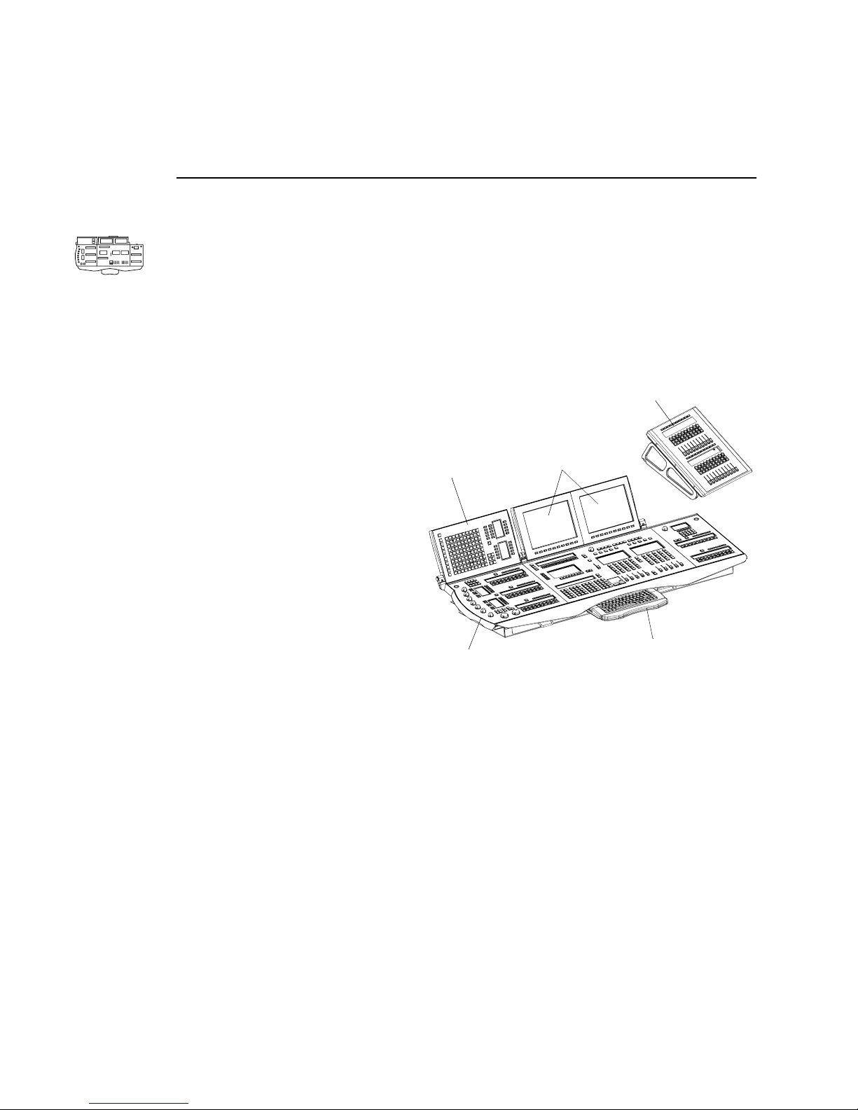
VARI❋LITE® - VIRTUOSO™ / VIRTUOSO™ DX CONSOLE USER’S MANUAL
Virtuoso Console
Features
The Virtuoso console is a control desk capable of operating VARI❋LITE luminaires,
DMX moving lights, and conventional lights. The console utilizes Virtuoso protocol
and/or DMX512 (via an associated Network Interface unit) to control the fixtures.
Virtuoso console features:
• Control of 2,000 multiple parameter luminaires.
• 2,000-10,000 cues per fixture (luminaire dependent).
• 1,000 presets.
Auxiliary Submasters
Panel (optional)
• 1,000 effects.
• 100 beam selects.
• 300 color selects.
Built-in Channel
Select Panel
Built-in
Monitors
• 1000 group selects.
• 1,000 board cues.
• 1,000 macros.
• 1,200 snapshots.
• 30 submasters (in 3 pages).
• Zip® drive for show file
backup.
Console
Built-in Keyboard
• CD ROM drive for software upgrades.
• Built-in hard drive for show file storage.
• Up to five V irtuoso con soles may be linked together to provide universal shared or
independent localized control of a single system.
• Fiber optic or Ethernet data link to system.
• Two built-in monitor displays with ports for two additional VGA monitors. (All
monitors form one seamless, virtual monitor.)
• Optional Auxiliary Submasters panel, which provides 20 additional submaster
faders to be added to the 10 submasters faders located on the Virtuoso console.
• Utilizes bi-directional protocol for VL2000™ luminaires.
6 23-Sep -02 02.9651.0001 C
Page 33
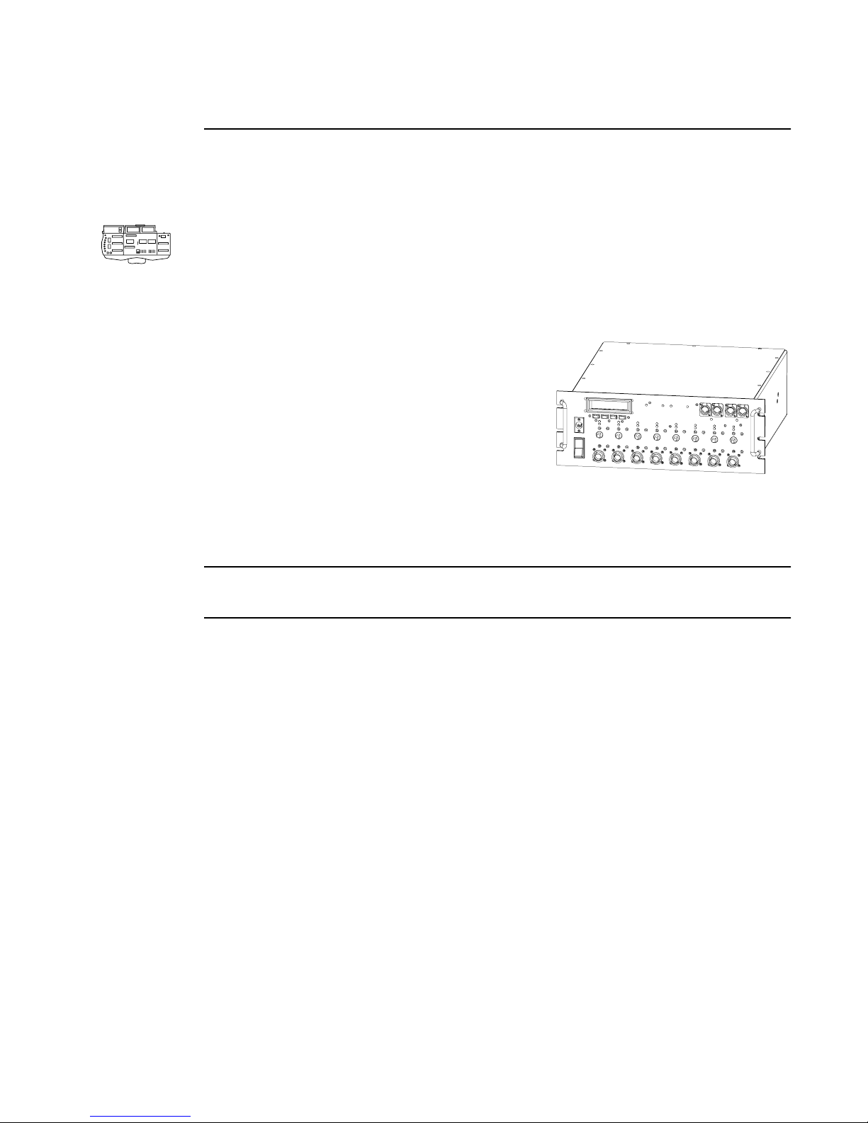
DESCRIPTIONS AND OVERVIEW : VIRTUOSO CONSOLE
1
Components
Console
The Virtuoso console itself contains buttons, keypads, encoders, faders, and displays
for the purpose of controlling luminaires. A built-in Macintosh CPU, keyboard,
trackpad and monitors allows integration of menu and window based commands.
Network Interface (NIF) Unit
The Series 300™ Network Interface unit (NIF) is
used in association with the Virtuoso console to
control a lighting system. Power for both the
console(s) and Series 300 luminaires (except
lamp power) is distributed from the NIF unit. All
data communication from the console to
luminaires passes through the NIF unit for
processing and distribution into V irtuoso protocol
and DMX512 protocol. Although a single NIF unit can support two V irtuoso consoles,
a single console can control lighting systems utilizing up to 99 NIF units when
arranged in a data loop.
Note: For more detailed installation and operation instructions for the NIF unit, refer
to the Virtuoso System Installation and Checkout Manual (02.3004.0400)
02.9651.0001 C 23-Sep-02 7
Page 34
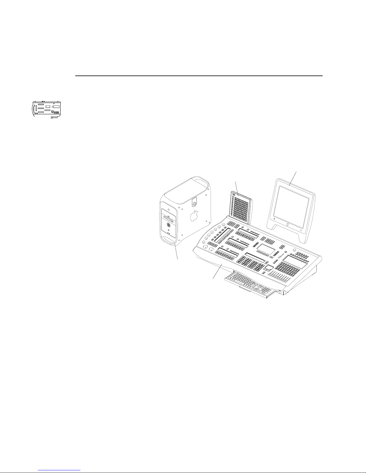
VARI❋LITE® - VIRTUOSO™ / VIRTUOSO™ DX CONSOLE USER’S MANUAL
Virtuoso DX Console
Features
The Virtuoso DX console is a control desk capable of operating VARI❋LITE
luminaires, DMX moving lights, and conventional lights. The console utilizes
DX
Virtuoso protocol and/or DMX512 to control the fixtures.
Virtuoso DX console features:
• Control of 2,000 multiple parameter luminaires.
• 2,000-10,000 cues per fixture (luminaire dependent).
• 1,000 presets.
• 1,000 effects.
Channel Select
Panel (optional)
Monitor
• 100 beam selects.
• 300 color selects.
• 1000 group selects.
• 1,000 board cues.
• 1,000 macros.
• 1,200 snapshots.
• 30 submasters (in 3
pages).
• 26 DMX universes.
Macintosh
G4 Computer
Console
• Up to five Virtuoso
consoles may be linked together to provide universal shared or independent
localized control of a single system.
• It includes eight integrated DMX universes and supports up to 26 DMX universes
with additional equipment.
• Supports an outboard Channel Select panel which allows instantaneous selection
and visible display of up to 2000 channels. (This component is optional and is not
required for console operation.)
• Utilizes bi-directional protocol for VL2000 luminaires.
8 23-Sep -02 02.9651.0001 C
Page 35
DX
DESCRIPTIONS AND OVERVIEW : VIRTUOSO DX CONSOLE
1
Components
Console
The Virtuoso DX console itself contains buttons, keypads, encoders, faders, and
displays for the purpose of controlling luminaires.
Macintosh Computer
An Apple® Macintosh® G4 computer provides the operating system CPU, supports
the display monitor(s), and provides a removable backup medium (such as a Zip®
drive) and CD or DVD ROM. The removable medium is primarily for importing,
exporting, and backing up show file data, while the CD/DVD ROM drive is primarily
for upgrading Virtuoso console software.
Minimum requirements for Macintosh computer system:
• Macintosh G4 OS9 or greater
• A monitor *
• Removable backup medium (Zip drive, etc.)
• CD/DVD-ROM
* Additional monitors can be supported by installing additional video cards. Please
call 1-877-VARI-LITE for most recent list of compatible video cards.
Note: Some Macintosh monitors shipped with the Virtuoso DX console have been
modified so that their power button is disabled. It has been discovered that there is a
design defect for this product where the button can be remotely activated by cellular
phone activity, resulting in shutdown of the Macintosh computer system during
console operation. The following sticker applied to the back of the monitor indicates
whether the power button has been disabled:
THE POWER BUTTON ON THIS MONITOR HAS BEEN DISABLED
SEE VIRTUOSO DX USERS MANUAL FOR DETAILS
02.9651.0001 C 23-Sep-02 9
Page 36
VARI❋LITE® - VIRTUOSO™ / VIRTUOSO™ DX CONSOLE USER’S MANUAL
Virtuoso DX Console Accessories List
The following accessories and/or replacement items can be ordered directly from VariLite. (Please order by Vari-Lite part number.)
DX
Vari-Lite Part No. Accessory
10.9668.0130 CONSOLE DUST COVER
20.9625.0142 CONSOLE ROAD CASE
20.9625.0143 MACINTOSH COMPUTER ROAD CASE
21.9668.0005 CHANNEL SELECT PANEL
52.6616.0780 MINI PHONE .141" MONO SHIELDED
2-COND SOLDER PLUG
71.5001.0003 GOOSENECK HI-INTENSITY DESK LAMP
call for details MACINTOSH MONITOR
call for details AUXILIARY MONITOR VIDEO CARD
The following accessories can be purchased from Vari-Lite or on the open market as
required.
Manufacturer Part No. Accessory
Switchcraft 780 MINI PHONE .141" MONO SHIELDED
2-COND SOLDER PLUG
Digi-Key SC1057-ND MINI PHONE .141" MONO SHIELDED
2-COND SOLDER PLUG
10 23-Sep-0 2 02.9651.0001 C
Page 37
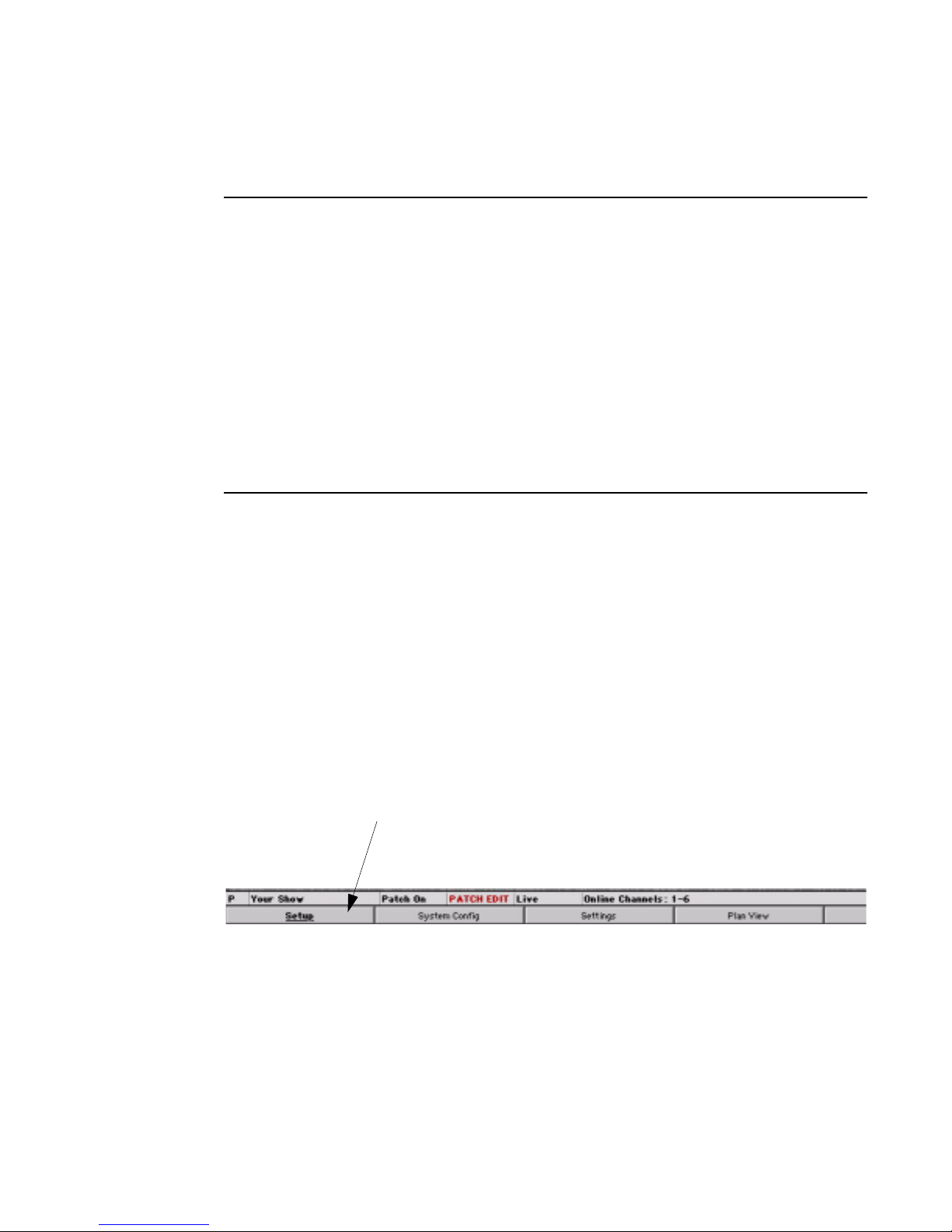
DESCRIPTIONS AND OVERVIEW : OPERATION OVERVIEW
Operation Overview
Virtuoso Application
The same Virtuoso application (software operating system) is used in both the
Virtuoso and Virtuoso DX consoles. As a result, the Macintosh-based windows and
menus operate identically . The only operational dif ference between these two consoles
is the hardware configuration of the desk itself. For example, if the Channel Select
panel (which is standard for the Virtuoso console) is not available on your Virtuoso
DX console, channels can be selected using another method such as the Macintosh
Channel Select window.
For the most part however , the consoles are oper ated very similar ly and the operational
instructions provided in this manual will apply to all versions unless otherwise noted.
Window Interaction
1
Menus and Button Bar
The Virtuoso application functions just as any standard Macintosh application.
A menu bar provides access to file management commands and Virtuoso system
windows. Virtuoso windows can also be accessed using the button bar at the bottom
of each installed monitor screen. Clicking the soft button with the cursor will open the
window (in the event it is closed), bring it to the front (if already open, but hidden), or
close it (if in the front). Clicking the far-left button (with the underlined name) will
page through the button bars to provide access to different Virtuoso windows and navigation controls.
Button bar
Click to page
through button bars
02.9651.0001 C 23-Sep-02 11
Page 38
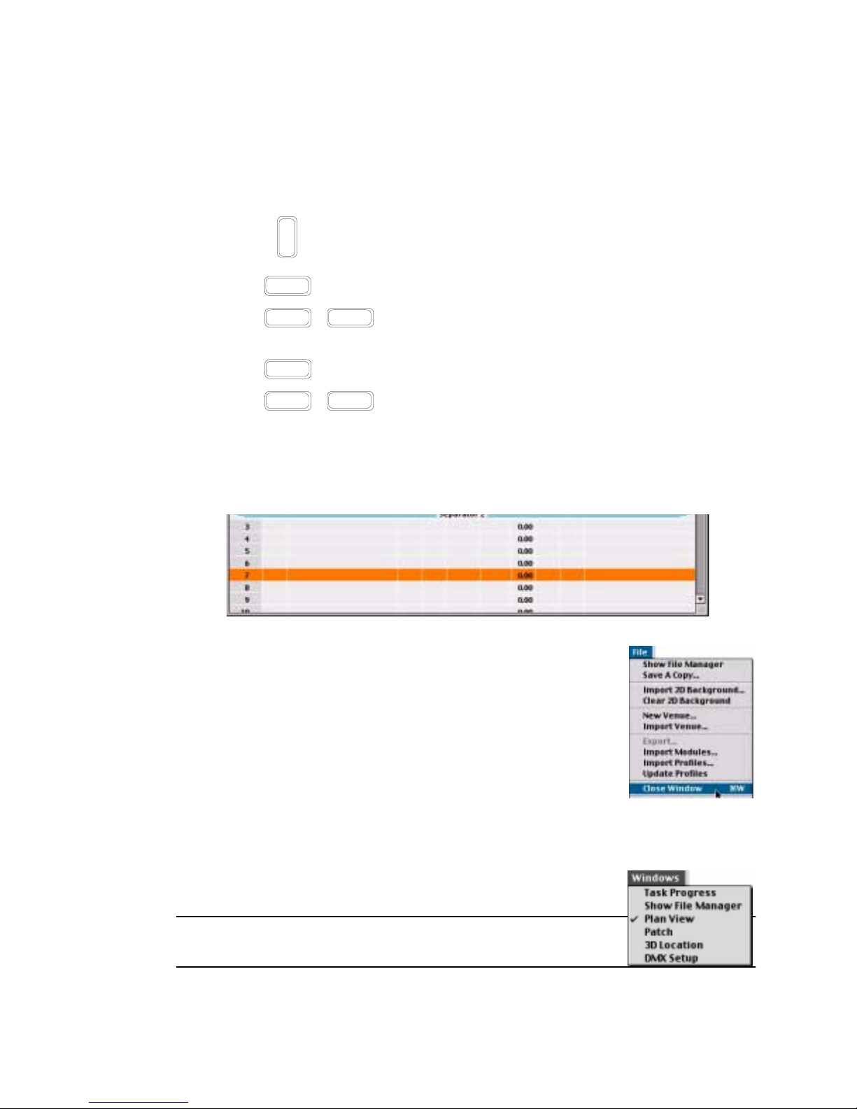
VARI❋LITE® - VIRTUOSO™ / VIRTUOSO™ DX CONSOLE USER’S MANUAL
Entering/Editing Window Data
The Macintosh keyboard can be used to type in alpha-numeric entries or select cells
and fields in the windows.
e
n
• Pressing closes the entry field.
t
e
r
• Pressing automatically selects the next c ell down in the column f or editing.
• Pressing / automatically selects the next cell up in the column for
return
Shift return
editing.
• Pressing selects the next cell or field in a row.
• Pressing / selects the previous cell or field in a row.
tab
Shift tab
• Use arrow buttons to move cursor through fields.
The trackpad can be used to manipulate the cursor for field/cell editing, clicking radio
buttons, accessing pop-up menus, moving windows, or closing windows.
Closing Windows
As with any Macintosh application, windows can be closed by
clicking the box in their left-hand corner. Windows can also be
closed from the File menu by selecting Close Window.
Locating Hidden Windows
When windows are open but hidden, use the Windows menu to
locate and bring to the front.
To bring window to front:
• At menu bar select the Windows menu, click on any window
to make it the front active widow.
Note: A checkmark will show which window is currently the
top active window.
12 23-Sep-0 2 02.9651.0001 C
Page 39
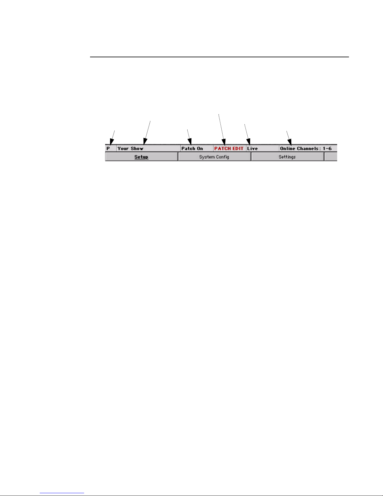
DESCRIPTIONS AND OVERVIEW : OPERATION OVERVIEW
1
Status Indicator Bar
Several indicators available at the lower portion of the screen provide an indication of
current console status and operations.
Current Showfile
Status / State Patch On/Off
Patch Edit Enabled/Disabled
Live/Preview/Offline Mode
Log Messages
Status/State
Indicates the console state or status in relationship to communication between the
Macintosh CPU and Console Interface Card (CIC). The following indications may be
displayed:
• P - Primary console.
• PP - Primary Prep: where the Mac opens the show file and initializes the CIC for
downloads.
• PL - Primary Load: where the show file is loaded to the CIC and Mac.
• PS - Primary Select: where a show file back up is being made or other act i on i s occurring
where the CIC is not immediately available for changes.
• U - Unknown state: where the CIC is no longer responding.
• ** - No CIC reply: where the CIC is not available or ready.
• NL - Net Listen: where the console checks for other active consoles on the network.
• ML - Mac Listen: where the CIC checks for a local Mac. (Not usually displayed.)
• S - Secondary console.
• SP - Secondary Prep: where the secondary console syncs the show file and saves it to
disk.
• SL - Secondary Load: where the secondary console loads the show file to the CIC.
• WP - Waiting for Primary: appears while the Waiting For Primary Dialog is open.
Current Showfile
Displays the name of the currently open show file.
Patch On/Off
Indicates whether patch is turned on or off. (Patch On/Off will be covered in the next
chapter.)
02.9651.0001 C 23-Sep-02 13
Page 40
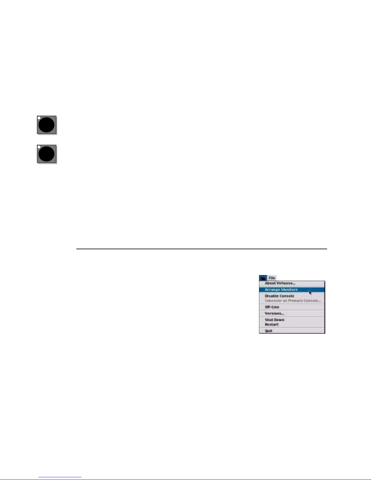
VARI❋LITE® - VIRTUOSO™ / VIRTUOSO™ DX CONSOLE USER’S MANUAL
Patch Edit Enabled/Disabled
"Patch Edit" is displayed when patch is enabled from the Patch menu.
The box is blank when patch editing is disabled from the Patch menu.
Live/Preview/Offline Mode
Indicates whether the console is in the Live, Preview or Offline mode.
Live
Pre-
View
The Live Mode is used for live editing. While the [Live] button is selected, any
manual control actions or event recalls (cues, effects, dynamic states, etc.) will be
executed, in real time, on stage.
The Preview Mode is used for preview editing. While the [Preview] button is
selected, any manual control actions are stored to the appropriate luminaires, but are
not executed on stage.
Refer to “Live/Preview Mode” on page 279 for complete instructions on these modes.
The Offline Mode allows preprogramming without having to connect to a system.
Refer to “Off-Line Programming” on page 266.
Log Messages
Messages highlighting in the Log Message box are the same messages collected in the
Console Log (refer to “Console Log” on page 290).
Arrange Monitors
The Arrange Monitors option arranges the monitors from left
to right according to the PCI order, sets size of monitors to
800x600 and sets the start up monitor and menu bar for
Monitor 1.
Select Arrange Monitors from the menu to activate.
14 23-Sep-0 2 02.9651.0001 C
Page 41

CHAPTER 2.
Installation
Installation
InstallationInstallation
This chapter provides instructions for installing a Virtuoso console and connecting
additional components.
• Virtuoso Console
• Virtuoso DX Console
02.9651.0001 C 23-Sep-02 15
Page 42
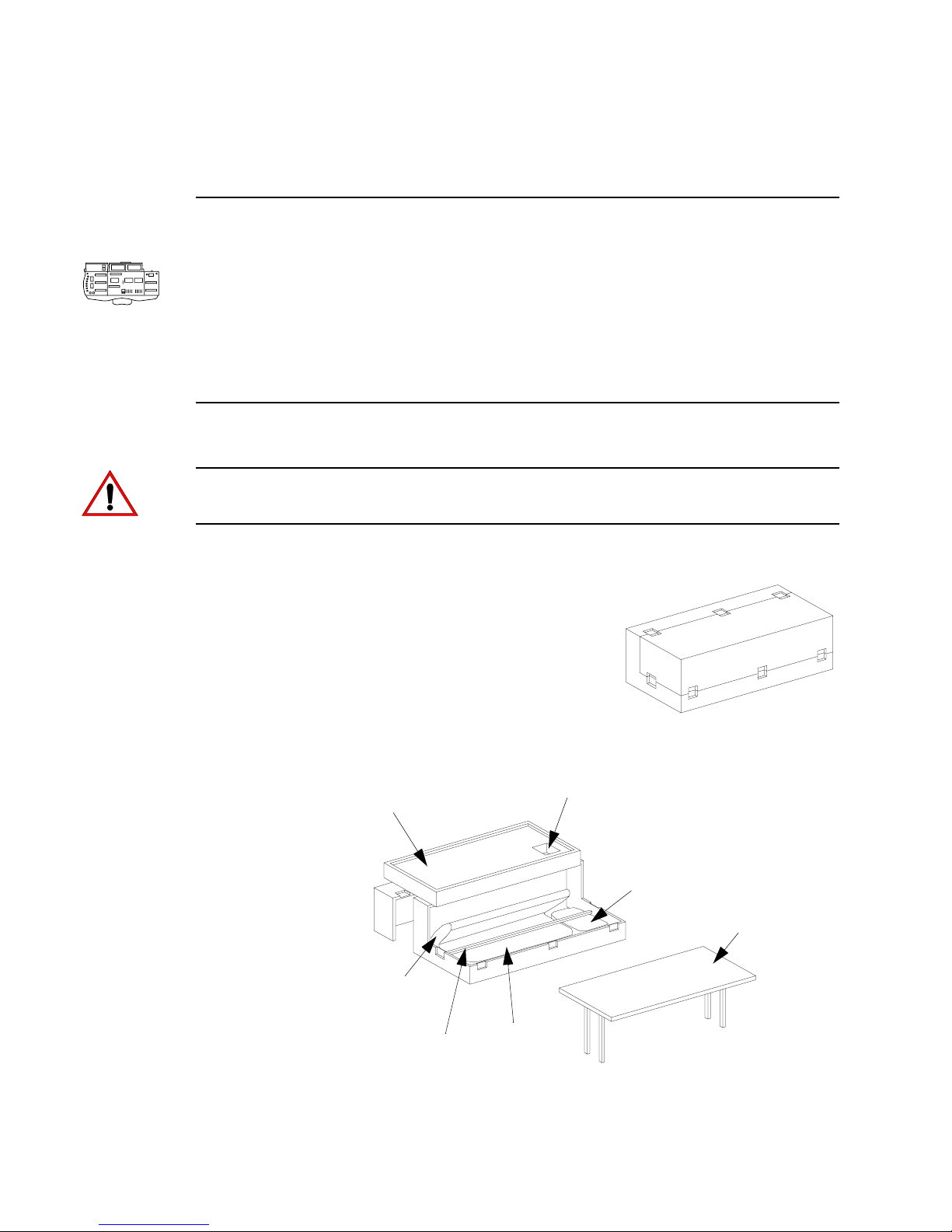
VARI❋LITE® - VIRTUOSO™ / VIRTUOSO™ DX CONSOLE USER’S MANUAL
Virtuoso Console
Overview
The following section provides instructions for connecting power, data and additional
components to the Virtuoso console. These instructions pertain only to the console
itself and do not provide details regarding the entire system hook-up. For more
detailed information on Virtuoso systems, refer to the Virtuoso System Installation
and Checkout Manual (02.3004.0400).
Unpacking Console Road Case
CAUTION: The Virtuoso console and case weighs approximately 400 lbs (182 kg)
and requires a minimum of two people for unpacking.
Unpack console case:
Step 1. Place console case on its side (as shown).
Step 2. Unlatch all latches.
Step 3. Remove case lid and set aside.
Step 4. Pull table partway out of case, raise legs, and
lock into place.
Step 5. Remove table and set upright on flat surface. Ensure that legs are properly
locked and will support weight of console.
Wedge
Tilt monitors 45 degrees
before sliding bar forward.
Cable storage
Auxiliary
Submasters Panel
(not required)
Table
Step 6. Remove wedge and set aside.
16 23-Sep-0 2 02.9651.0001 C
Support Bar
Console
Page 43
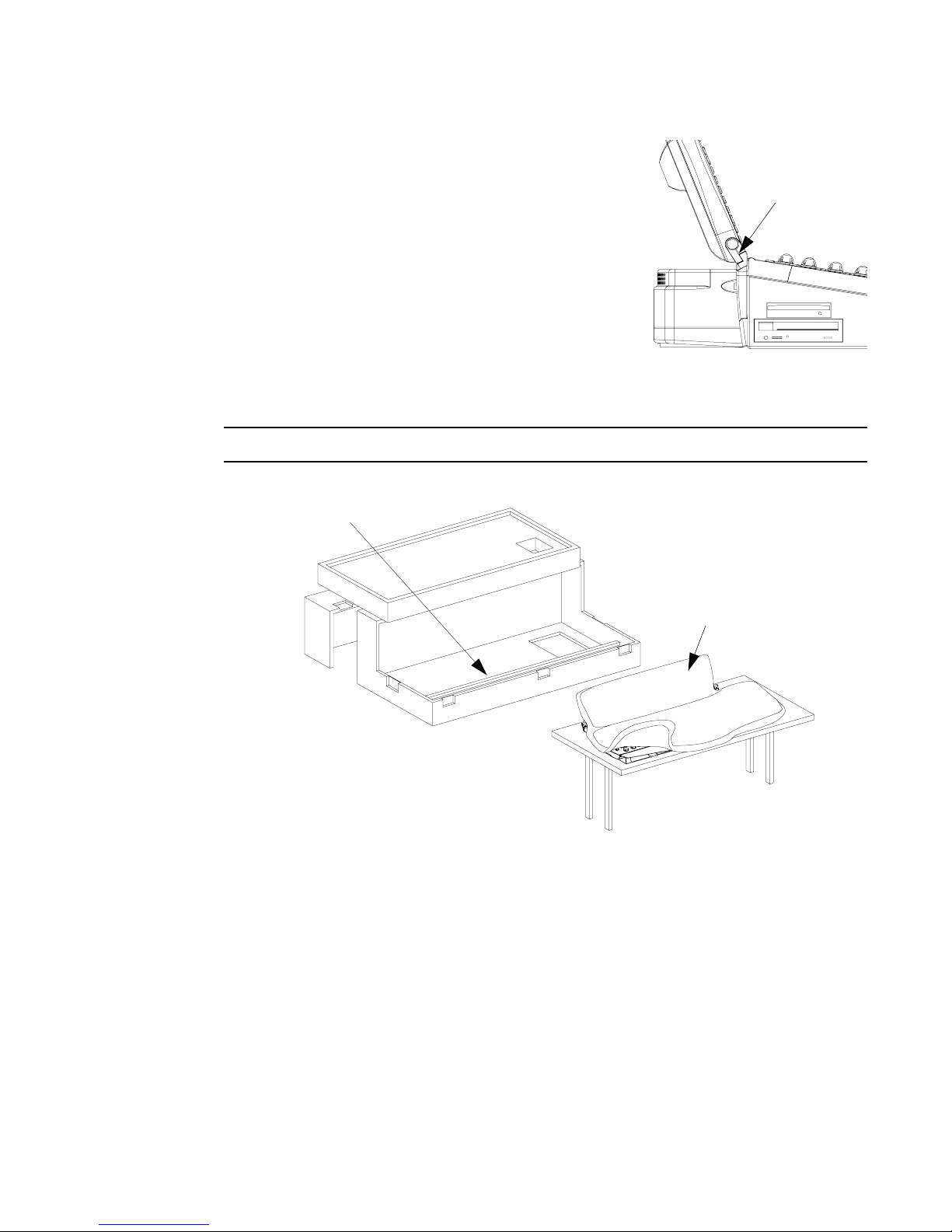
INSTALLATION : VIRTUOSO CONSOLE
Step 7. At console, loosen monitors by flipping
locking bar and reposition monitors at about a
45 degree angle, retightening locking bars.
Step 8. Slide support bar to front of case.
Step 9. If included, remove auxiliary submasters
panel and set aside.
Step 10. Using at least two people, remove console
from case and place securely on table
(removing console will require one person to
stand in case in order to lift properly).
Step 11. Remove dust cover.
Note: Recover console when powered down and not in use.
Bar slides forward
2
Monitor
Locking Bar
Dust Cover
Step 12. Remove cables from wedge compartment and place wedge back inside case.
Step 13. Re-attach case lid and set case aside.
Step 14. Re-adjust console monitors as desired.
02.9651.0001 C 23-Sep-02 17
Page 44
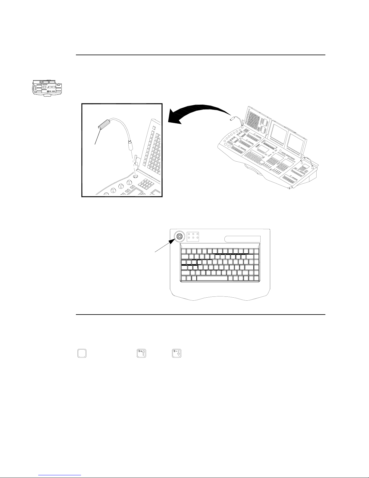
VARI❋LITE® - VIRTUOSO™ / VIRTUOSO™ DX CONSOLE USER’S MANUAL
Installing Desk Lamps
Install desk lamps at console front panel.
Desk Lamp
Virtuoso Front Pane l
The intensity of the desk lamps can be adjusted from the console’s pull-out keyboard.
Desk lamp intensity
adjustment knob
Pull-Out Keyboard Backlighting Adjustment
The intensity of the pull-out keyboard backlighting can be adjusted by holding down
FN
, while pressing (up) or (down) as required.
18 23-Sep-0 2 02.9651.0001 C
Page 45
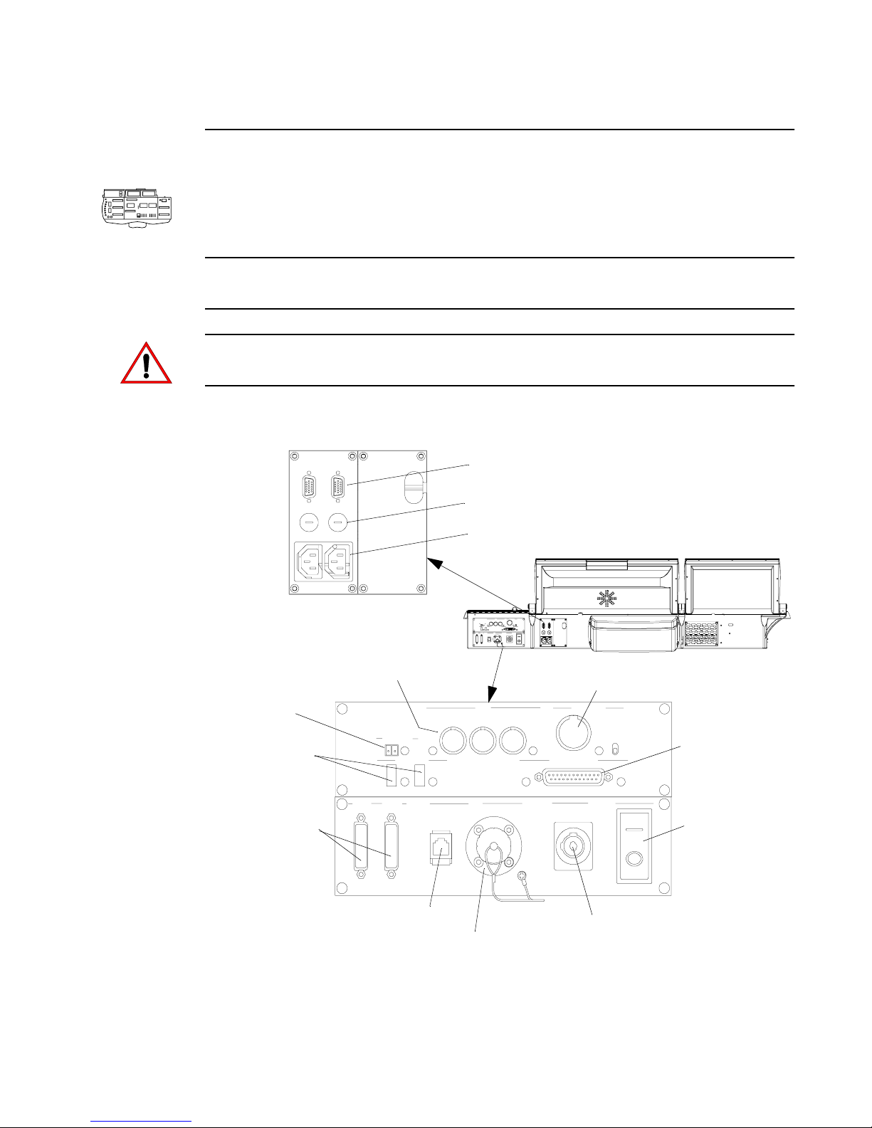
INSTALLATION : VIRTUOSO CONSOLE
2
Connecting Optional Components
Connectors at the console’s rear panel allow connection of additional monitors, USB
peripherals, auxiliary submasters panel, MIDI devices, and a board cue switch closure
trigger device.
Note: Refer to “Input Options” on page 305 for information on constructing a switch
closure device.
CAUTION: Monitor power outlets are not always 110VAC. Outlets supply 208VAC
in U.S. on a Delta system.
Additional VGA monitor ports (2)
MIDI connections for prerecorded music synchronizing
Trigger contact closure
for use w/ external board
cue triggering device
USB accessory connections
(printer, mouse, etc.)
Auxiliary Submaster s
panel connections
Fuse holders
110/220VAC outlets for monitors (2)
For Future Use
In Thru Out
For Future Use
Main power
breaker
02.9651.0001 C 23-Sep-02 19
Ethernet connection
to NIF unit
Optic fiber connection
to NIF unit
Neutrik Powercon
AC input from NIF unit
Page 46
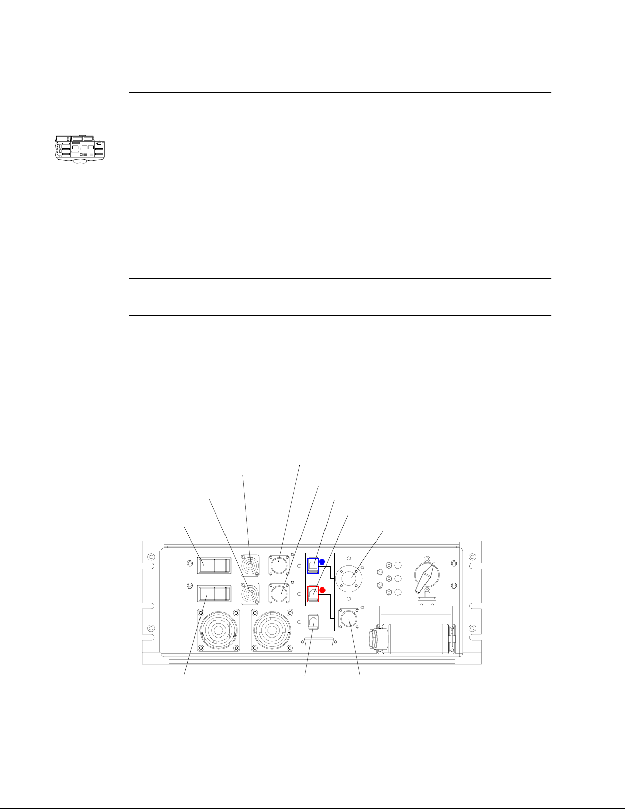
VARI❋LITE® - VIRTUOSO™ / VIRTUOSO™ DX CONSOLE USER’S MANUAL
Connecting To System
Connectors at the console’s back panel allow connection to the lighting system.
Console connections:
Step 1. At console back panel, connect fiber optic cable (to NIF unit).
Step 2. Connect Neutrik Powercon cable (from NIF unit).
Step 3. Connect Ethernet cables as required.
Step 4. Connect MIDI input cables as required.
NIF unit(s) connections:
Note: (It is recommended that main console be connected to NIF inputs A and backup
console be connected to a separate NIF unit.)
Step 1. Connect Neutrik Powercon cable (to console).
Step 2. Connect fiber optic cable (from console).
Step 3. Connect NIF data loop cables as required. These can be either optic cables or
copper Ethernet cables in any combination as long as only one input and only
one output is used (e.g. when a cable is plugged into the copper Ethernet
input port, the corresponding optic cable input port is disabled).
Neutrik Powercon
outlet for Console A
Neutrik Powercon
outlet for Console B
Console A
Power switch
Optic cable to Console A
Optic cable to Console B
Copper Ethernet cable input for NIF data loop
Copper Ethernet cable output for NIF data loop
Optic cable input for NIF data loop
Console B
Power switch
20 23-Sep-0 2 02.9651.0001 C
Auxiliary Ethernet
Optic cable output
for NIF data loop
NIF Unit
(w/ Copper Mod)
Page 47
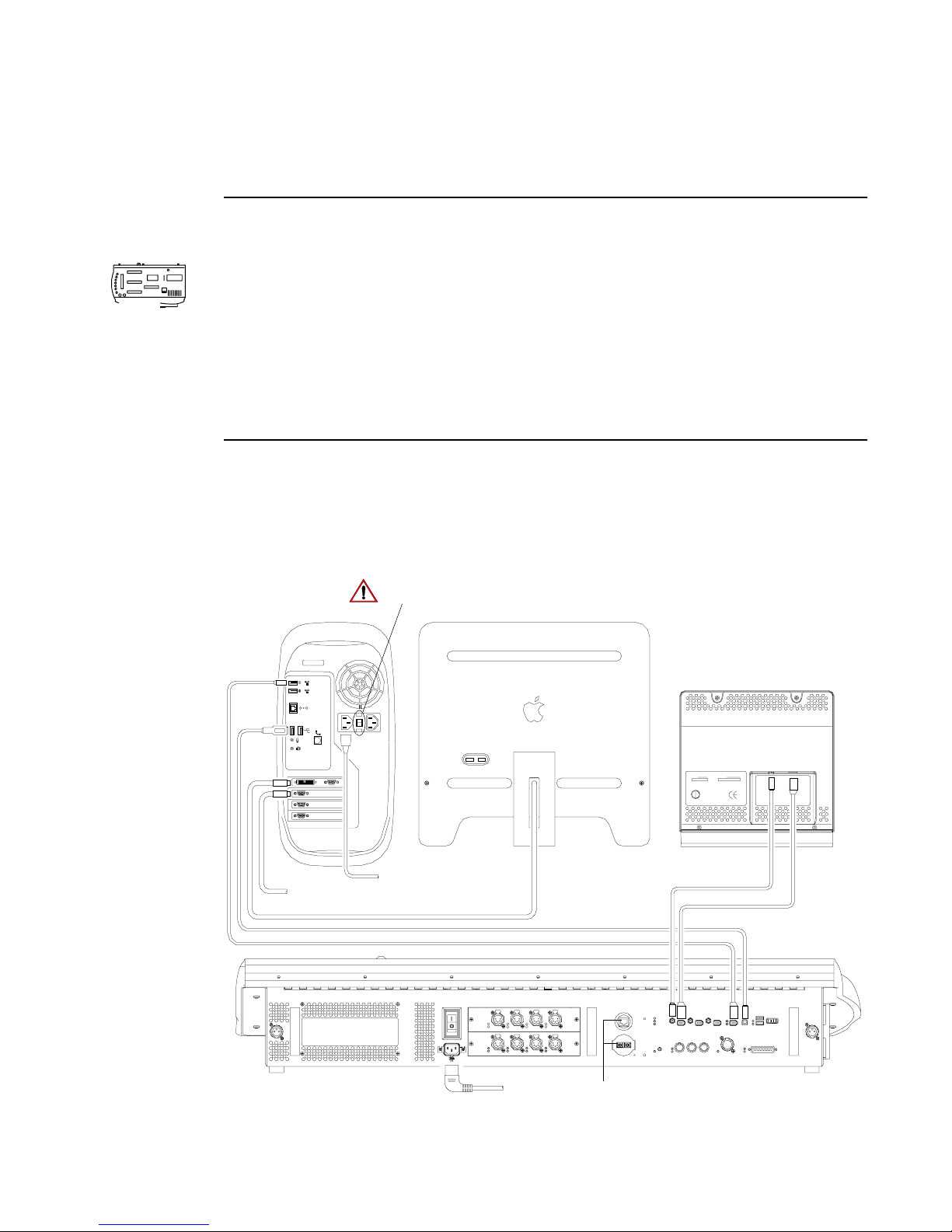
Virtuoso DX Console
Overview
The following section provides instructions for connecting power, data and additional
components to the V irtuoso DX console. These instructions pertain only to the console
DX
and associated Macintosh computer, and do not provide details regarding the entire
system hook-up. For more detailed information on Virtuoso systems, refer to the
Virtuoso System Installation and Checkout Manual (02.3004.0400). (For instructions
on configuring multiple consoles in a standard Ethernet system, refer to “Connecting
Virtuoso DX Backup in Standard Ethernet Systems” on page 264.)
Connecting Console & Computer Components
The V irtuoso DX console system will require inter-connection of the console desk and
Macintosh G4 computer components.
INSTALLATION : VIRTUOSO DX CONSOLE
2
To connect components:
Macintosh
Computer
FireWire
USB
To Optional
Secondary Monitor
Caution: Set voltage selector switch
To Power
to proper setting.
Monitor Power/Data
Monitor
Channel Select Panel
(optional)
Power Cable
FireWire
DX Console
*
02.9651.0001 C 23-Sep-02 21
To Power
* Note: Any of the three Aux ports can be used to connect the Channel Select panel.
Expansion Connectors
Page 48
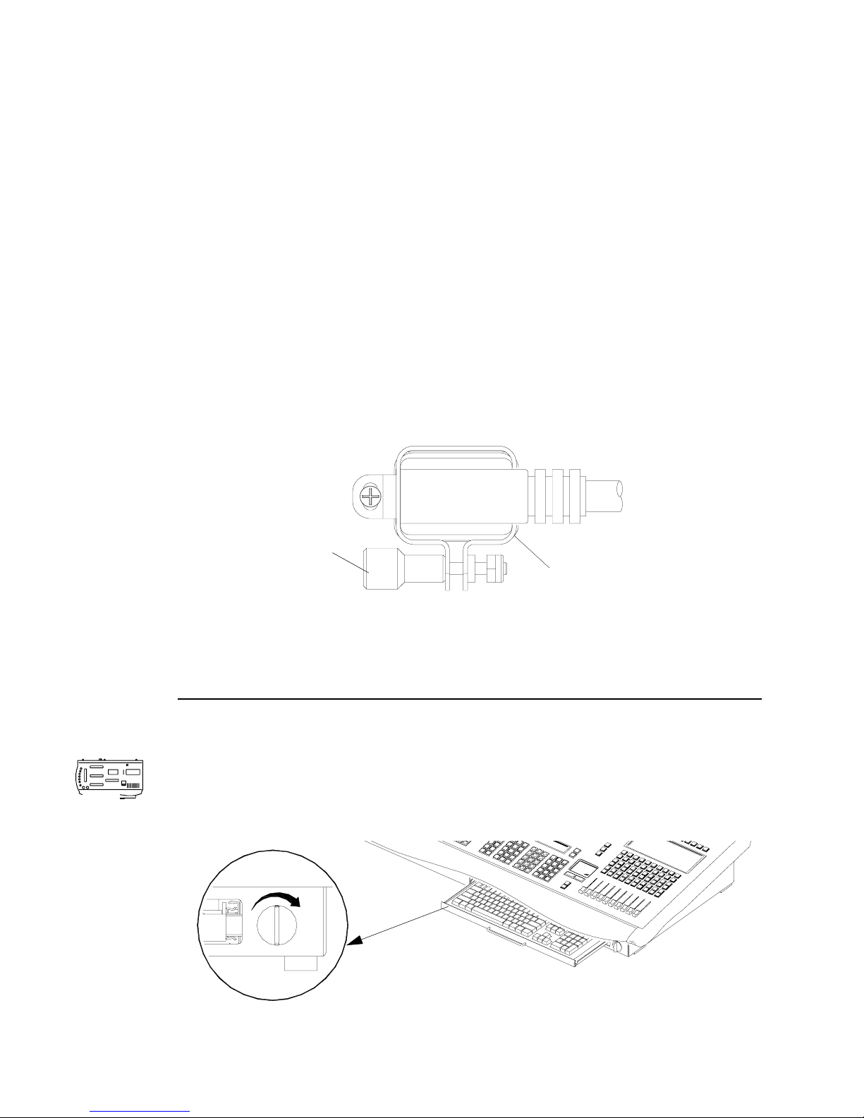
VARI❋LITE® - VIRTUOSO™ / VIRTUOSO™ DX CONSOLE USER’S MANUAL
Step 1. Connect power/data cable from primary monitor to first (top) monitor port at
Macintosh computer. (Connect secondary monitors to additional video ports
as required. Additional video cards will not be installed unless requested.)
Step 2. Connect FireWire® from console CPU port to either comm port (1 or 2) at
Macintosh computer.
Step 3. Connect USB cable from console USB port to either USB port (1 or 2) at
Macintosh computer.
Step 4. If used, connect system comm cable (Ethernet or Fiber) to appropriate
console SYSTEM COMM port.
Step 5. Connect DMX cables to DMX output connectors as required.
DX
Step 6. Connect power cable to console. (Console requires:
or 1.0 A at 240 V 50/60 Hz
). Lock power cable in place by tightening
2.0 A at 120 V 50/60 Hz
retaining bracket as shown.
Tighten s c rew to
lock in place
Retaining Bracket
Step 7. Connect power cable to computer. Ensure that voltage selector switch on
back of computer is set correctly.
Step 8. If applicable, connect Channel Select FireWire and power cables to console.
Keyboard Lock/Unlock
The pull-out drawer for the Macintosh alpha-numeric keyboard can be locked in place
for transport. To unlock drawer, turn knob clockwise. (Once drawer has been pushed
in, turn knob counter-clockwise to lock.)
To Unlock
22 23-Sep-0 2 02.9651.0001 C
Page 49
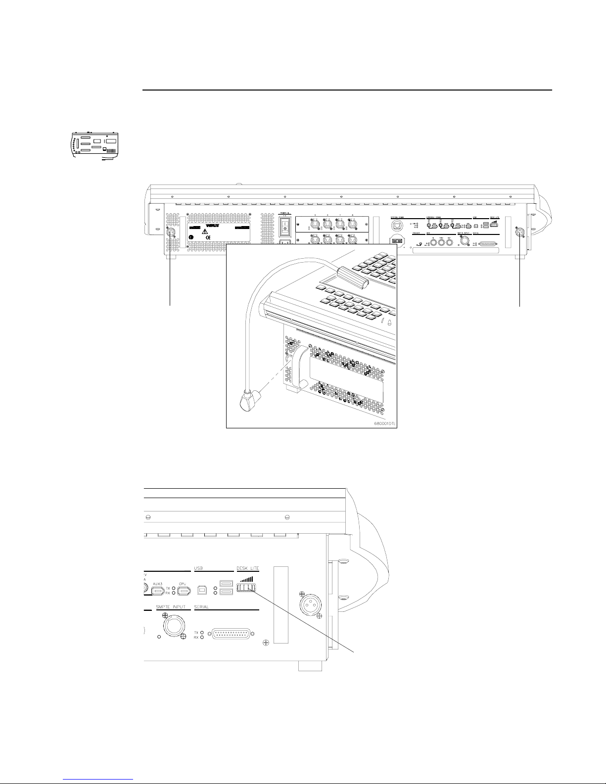
INSTALLATION : VIRTUOSO DX CONSOLE
Installing Desk Lamps
Install desk lamps at console rear panel.
2
DX
Virtuoso DX Console (Desk) Rear Panel
201 REGAL ROW
R
US
TYPE 1 ENCLOSURE
CONFORMS TO
UL STD 508
CERTIFIED TO
CSA C22.2 No.14
VIRTUOSO DX CONTROL CONSOLE
DALLAS, TX. 75247 U.S.A.
TM
1.877.VARILITE
WWW.VARI−LITE.COM
CAUTION: Hazard of electrical shock. Disconnect power before servicing.
Servicing by qualified personnell only. Refer to service manual before
operating or servicing product. NOT FOR RESIDENTIAL USE.
ATTENTION: Couper Le Courant avant D’entretenir.
THIS DEVICE COMPLIES WITH PART 15 OF THE FCC RULES. OPERATION IS SUBJECT TO
THE FOLLOWING TWO CONDITIONS: (1) THIS DEVICE MAY NOT CAUSE HARMFUL
INTERFERENCE, AND (2) THIS DEVICE MUST ACCEPT ANY INTERFERENCE RECEIVED,
INCLUDING INTERFERENCE THAT MAY CAUSE UNDESIRED OPERATION.
MFR Date: Serial Number:
Input Rating:
100−240VAC, 50/60 Hz 2A
C
L
DI
TSE
2000851
Desk Lamp
Desk Lamp
Connector
Desk Lamp
Connector
The brightness of the desk lamps can be adjusted at the console rear panel using the
intensity knob.
02.9651.0001 C 23-Sep-02 23
Desk Lamp Brightness
Adjustment Knob
Page 50
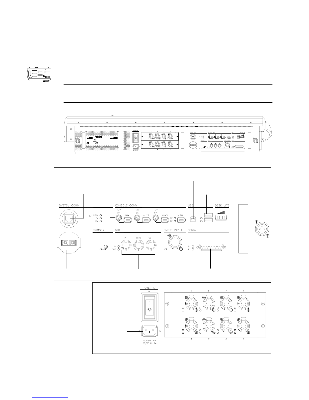
VARI❋LITE® - VIRTUOSO™ / VIRTUOSO™ DX CONSOLE USER’S MANUAL
Connecting Additional Components
Connectors at the console’s rear panel allow connection of USB peripherals, auxiliary
submasters panel, MIDI devices, and a board cue switch closure trigger device.
DX
Note: Refer to “Input Options” on page 305 for information on constructing a switch
closure device.
DX Console (Desk) Rear Panel
201 REGAL ROW
R
US
CONFORMS TO
CERTIFIED TO
CSA C22.2 No.14
TYPE 1 ENCLOSURE
VIRTUOSO DX CONTROL CONSOLE
UL STD 508
DALLAS, TX. 75247 U.S.A.
TM
1.877.VARILITE
WWW.VARI−LITE.COM
CAUTION: Hazard of electrical shock. Disconnect power before servicing.
Servicing by qualified personnell only. Refer to service manual before
operating or servicing product. NOT FOR RESIDENTIAL USE.
ATTENTION: Couper Le Courant avant D’entretenir.
THIS DEVICE COMPLIES WITH PART 15 OF THE FCC RULES. OPERATION IS SUBJECT TO
THE FOLLOWING TWO CONDITIONS: (1) THIS DEVICE MAY NOT CAUSE HARMFUL
INTERFERENCE, AND (2) THIS DEVICE MUST ACCEPT ANY INTERFERENCE RECEIVED,
INCLUDING INTERFERENCE THAT MAY CAUSE UNDESIRED OPERATION.
MFR Date: Serial Number:
Input Rating:
100−240VAC, 50/60 Hz 2A
C
L
DI
TSE
2000851
Detail A
Fiber Port
Auxiliary Components Power and Data Ports
(Channel Select Panel, etc.)
Ethernet Port
Switch Closure
Trigger Port
MIDI In, Thru, and Desk Lamp
Detail B
Mac Computer
Mac Computer
FireWire Port
SMPTE Input
Connection
USB Port
USB Device Ports
(Mouse, trackball, etc.)
reserved
ConnectorOut Connections
Console Power
Cable Connection
24 23-Sep-0 2 02.9651.0001 C
DMX512 XLR 5-Pin Connectors
Page 51

CHAPTER 3.
Power-Up and Pa tch
Power-Up and Pa tch
Power-Up and Pa tchPower-Up and Pa tch
This chapter provides instructions for powering up and patching your system so that
you will have control of the connected devices.
• Power Up - DMX Systems (Virtuoso DX Only)
• Power Up - VARI❋❋❋❋LITE Systems Using NIF Units
• Patch
• Patch Editing
02.9651.0001B 16-Apr-02 25
Page 52
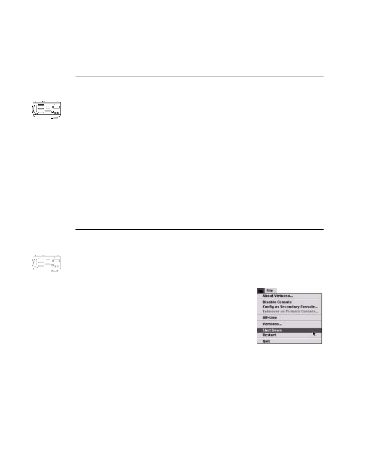
VARI❋LITE® - VIRTUOSO™ / VIRTUOSO™ DX CONSOLE USER’S MANUAL
Power Up - DMX Systems (Virtuoso DX Only)
Powering Up Console
Once your Virtuoso DX console has been connected to the system, you will need to
power up the console and verify status of the connected devices. In the event you are
DX
operating a V irtuoso DX console in a DMX-only system, the information displayed in
the System Configuration window will be different than when operating in a
VARI❋LITE system.
To power up console and verify system connections:
Step 1. At rear of console, set power switch to ON position.
Step 2. At Macintosh computer, press power button.
Step 3. Wait for console panels to initialize and Virtuoso application to launch. A
new show file (or last open show file) will automatically open.
DX
Step 4. Verify that your console appears in System Configuration window. Refer to
“System Configuration Window” on page 27.
Powering Down Console
When powering down the console for storage or in the event a restart is required, use
the following procedure.
To power down console:
Step 1. At Virtuoso menu, select Shut Down .
Step 2. At rear of console, set power switch to OFF
position.
26 1 6-Apr-02 02.9651.0001B
Page 53
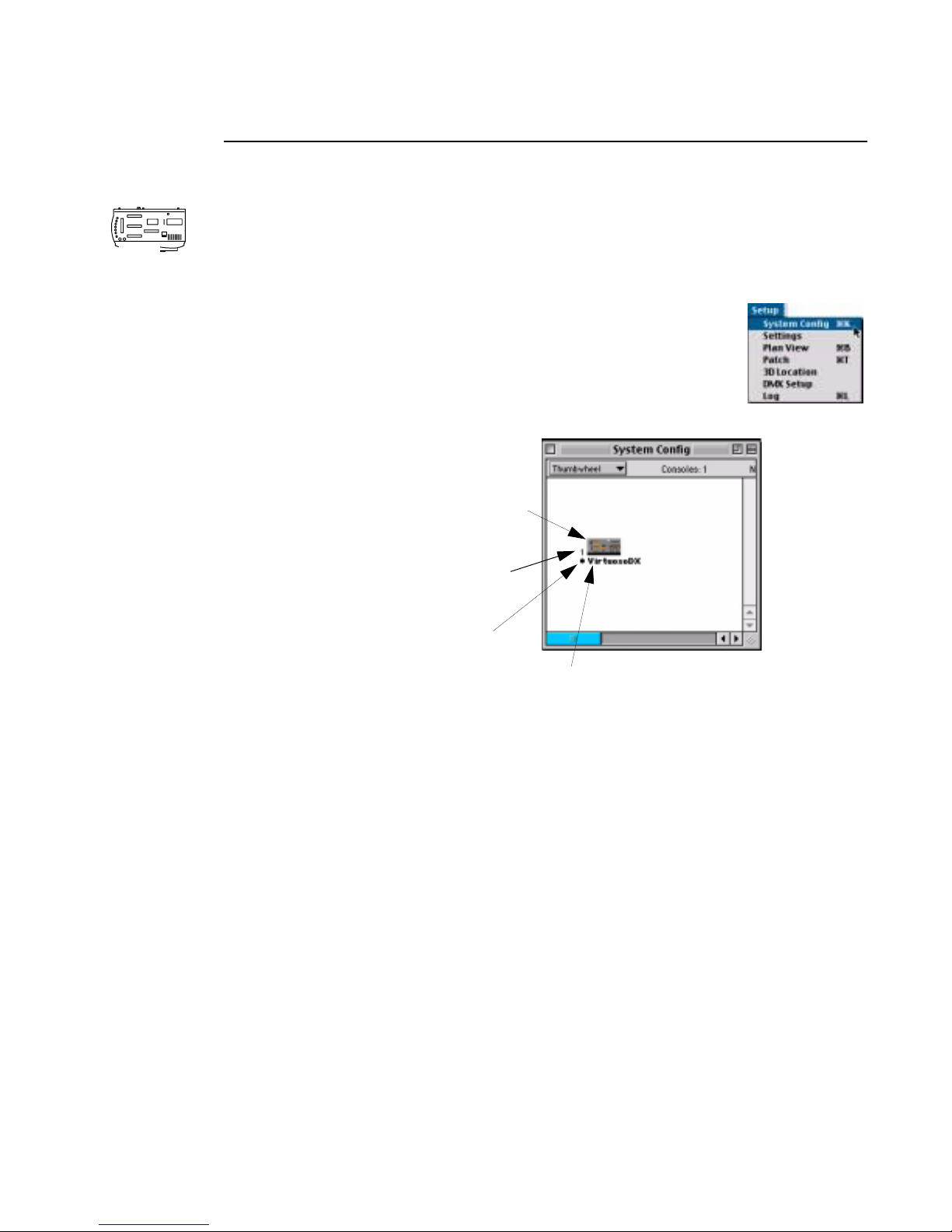
DX
POWER-UP AND PATCH : POWER UP - DMX SYSTEMS (VIRTUOSO DX ONLY)
3
System Configuration Window
When in a DMX environment, the System Configuration (Config) window displays
the console icon. This allows access to console naming and software version
information. It also displays the offline indicator when the system is running in of fline
mode (refer to “Off-Line Programming” on page 266).
To open System Configuration window, select System Config at
Setup menu.
Double-click icon
to open Versions
window for naming
Number indicates how many
consoles have been used to
open the file
Dot indicates
Primary console.
Bold indicates "this"
console (console
you are operating on)
Unique
console name
The window displays and keeps track of the following information:
• Console hardware ID number. A unique ID number will be generated for each
console that opens a single show file. When a new show file is created, the
console ID number will always be (1) one.
02.9651.0001B 16-Apr-02 27
Page 54

VARI❋LITE® - VIRTUOSO™ / VIRTUOSO™ DX CONSOLE USER’S MANUAL
Power Up - V ARI❋LITE Systems Using NIF
Units
Powering Up Console and NIF Units
Once your console has been connected to the system, you will need to power up the
console and verify status of the connected devices. The System Configuration
window displays each device’s thumbwheel address, which can then be used to patch
your system.
To power up console and verify system connections:
Step 1. (Virtuoso console) At rear of console, set power switch to ON position. Pre ss
illuminated power switch beneath console wrist rest or press keyboard power
key .
(Virtuoso DX console) At rear of console, set power switch to ON position.
At Macintosh computer, press power button.
Step 2. Wait for console panels to initialize and Virtuoso application to launch in
display monitor . A new show file (or last open show file) will automatically
open.
Step 3. Power up NIF unit(s) and allow boot-up process to complete.
Step 4. Power up devices connected to NIF unit(s).
Step 5. Verify that your lighting system devices appear in System Configuration
window (this verifies that data communication is present). Refer to “System
Configuration Window” on page 29. If any devices are not present, check
system connections and power.
Step 6. Once everything is verified as online, store configuration. Refer to “Store
Configuration” on page 31.
Powering Down Console
When powering down the console for storage or in the event a restart is required, use
the following procedure.
To power down console:
Step 1. At Virtuoso menu, select Shut Down .
Step 2. At rear of console, set power switch to OFF position.
28 1 6-Apr-02 02.9651.0001B
Page 55
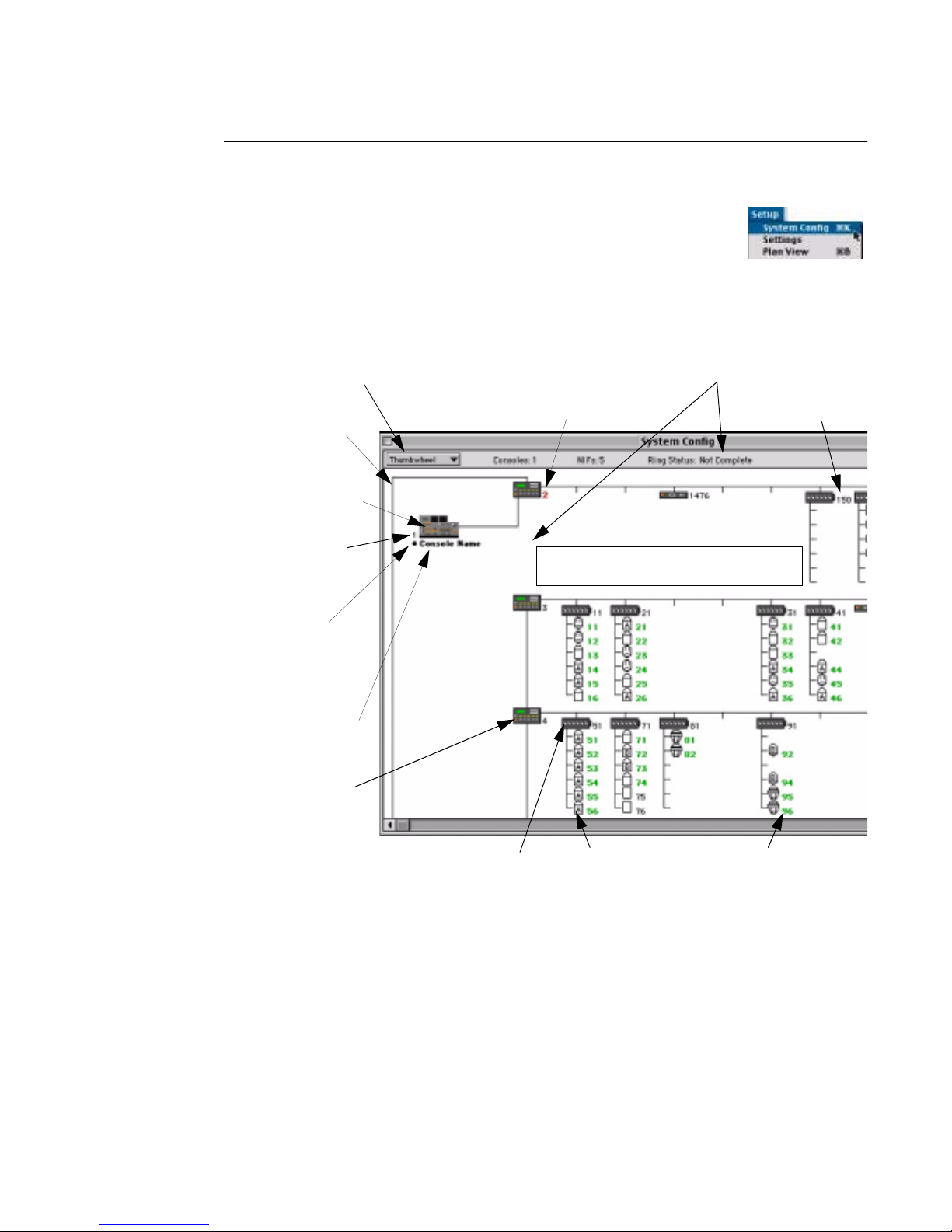
POWER-UP AND PATCH : POWER UP - VARI
❋❋❋❋
LITE SYSTEMS USING NIF UNITS
3
System Configuration Window
When in a VARI❋LITE comm environment, the System
Configuration (Config) window is a representation of your physical
system of consoles, NIF units, VARI❋LITE Series 300 luminaires,
and interface devices (i.e. UDM™ unit, SPC-36™ interface). The window is
associated with a specific show file so that you can keep track of system information
based on each show. To open the System Configuration window, select System
Config at the Setup menu.
Displays by Channel or Thumbwheel
Physica l ring
connections
Double-click icon
to open Versions
window for naming
Number indicates how many
consoles have been used to
open the file
Dot indicates
Primary console.
Bold indicates "this"
console (console
you are operating on)
Unique
console name
NIF Unit
Addresses displayed in red indicate
that device is reporting errors
Devices missing from a previously stored
configuration will appear “grayed out”
Indicates a break in the ring
Thumbwheel
Address
The window displays and keeps track of the following information:
• Device Icon. An icon which represents the specific device type is displayed in
relation to its position in the system. In stored configurations, the icon may appear
“grayed out” if the device is not online to indicate a problem. Double-click the
device to bring up the Device Info window which shows messages for that device
(also see “Error Log” on page 298).
• Channel/Thumbwheel Address. Channel assignment or thumbwheel address
(depending on setting) is displayed for each device. This number will change from
black to green as the device comes online. If the device is reporting any errors, the
number will be displayed in red.
02.9651.0001B 16-Apr-02 29
Luminaire Icon Green indicates "online"Smart Repeater Unit
Page 56
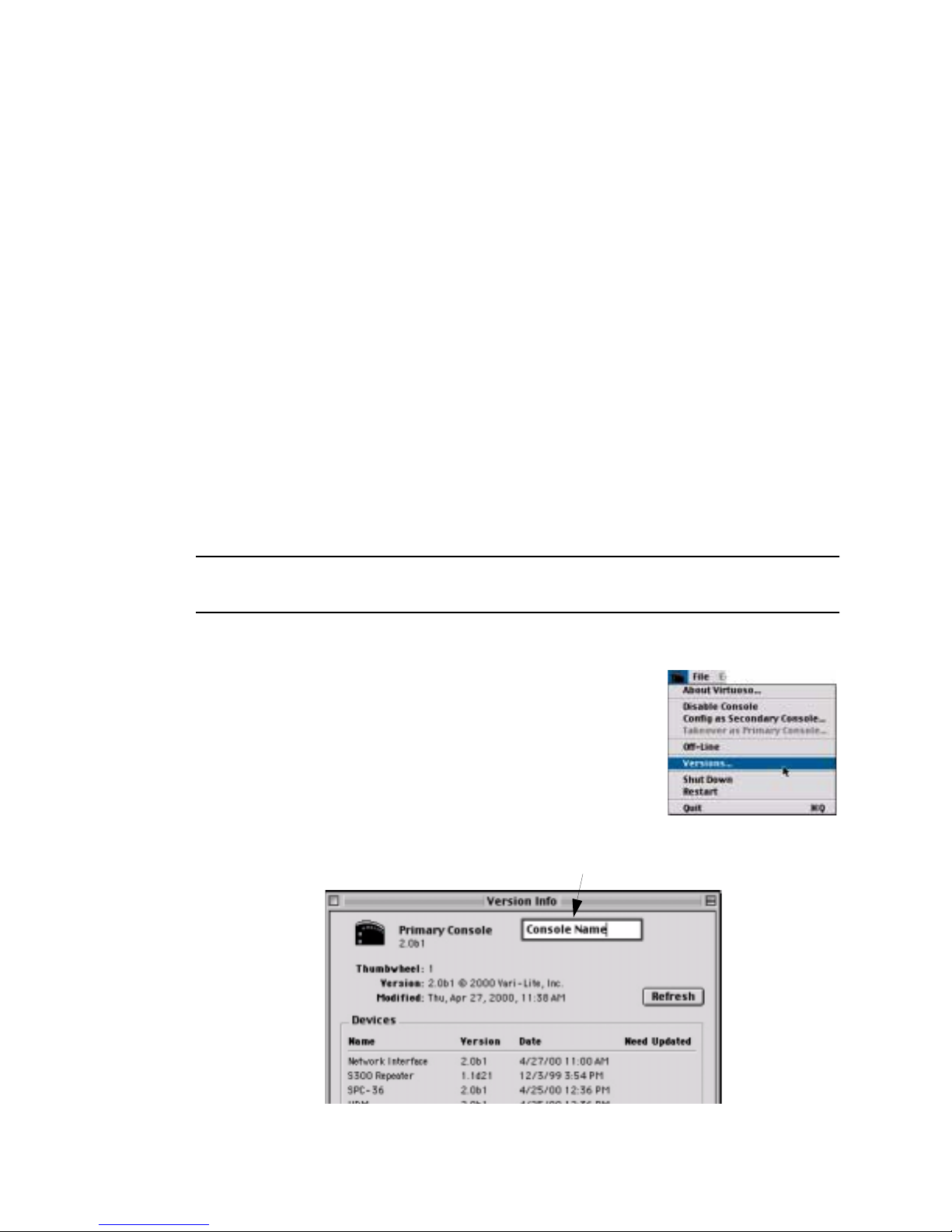
VARI❋LITE® - VIRTUOSO™ / VIRTUOSO™ DX CONSOLE USER’S MANUAL
• Console hardware ID number. A unique ID number will be generated for each
console that opens a single show file. When a new show file is created, the
console ID number will always be (1) one.
• Physical Ring. The System Configuration window represents your system’s
physical "ring" of devices. The consoles and devices are displayed and connected
by cabling lines in their actual order in the system. If a device is off-line or not
communicating, this will be reflected by a break in the ring.
• NIF Icon. The NIF icon is displayed in color with an indication to show if the
DMX board is not online. If the box in the right-hand corner is red, the board is
not online (or not installed).
Console Naming
The console naming feature is useful when two consoles are connected to a single
system - also refer to “Setting Up a Backup Console” on page 262 - to identify each
console. For example, you could name the consoles "Main" and "Backup." For each
console, the name is displayed in its Versions window and underneath its System
Configuration icon.
Note: A console displays its own name in bold underneath the icon. All others will
appear in a regular font.
Name a console:
Step 1. At System Configuration window, double-click
icon of console to be named or at Virtuoso icon
menu, select Versions... Versions window will
open.
Step 2. At name field, type console name.
Step 3. Close window. (Name can be changed at anytime
by re-opening window and typing in new name.)
Type name for console
30 1 6-Apr-02 02.9651.0001B
Page 57
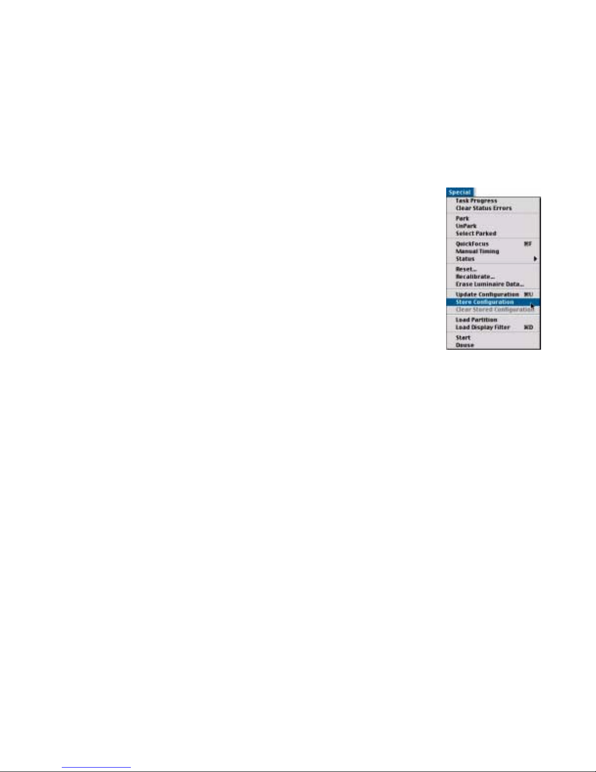
POWER-UP AND PATCH : POWER UP - VARI
❋❋❋❋
LITE SYSTEMS USING NIF UNITS
3
Store Configuration
Your system setup displayed in the System Configuration window can be stored for
future reference. Once stored, in the event a device is not online when the system is
powered up, the missing device’ s icon would appear “grayed out” in the window. This
aids in detecting online problems by showing where an item should be if it is not
reporting back.
Store a system configuration:
•At Special menu, select Store Configuration.
Clear a stored configuration:
•At Special menu, select Clear Stored Configuration.
Update Configuration
In the event a new device(s) is added to your system while the
console is powered up, the system can be repolled so that the
new device(s) will appear in the System Configuration
window. (This is not related to the “Stored Configuration”
function.)
Update a configuration:
•At Special menu, select Updat e Configuration.
02.9651.0001B 16-Apr-02 31
Page 58
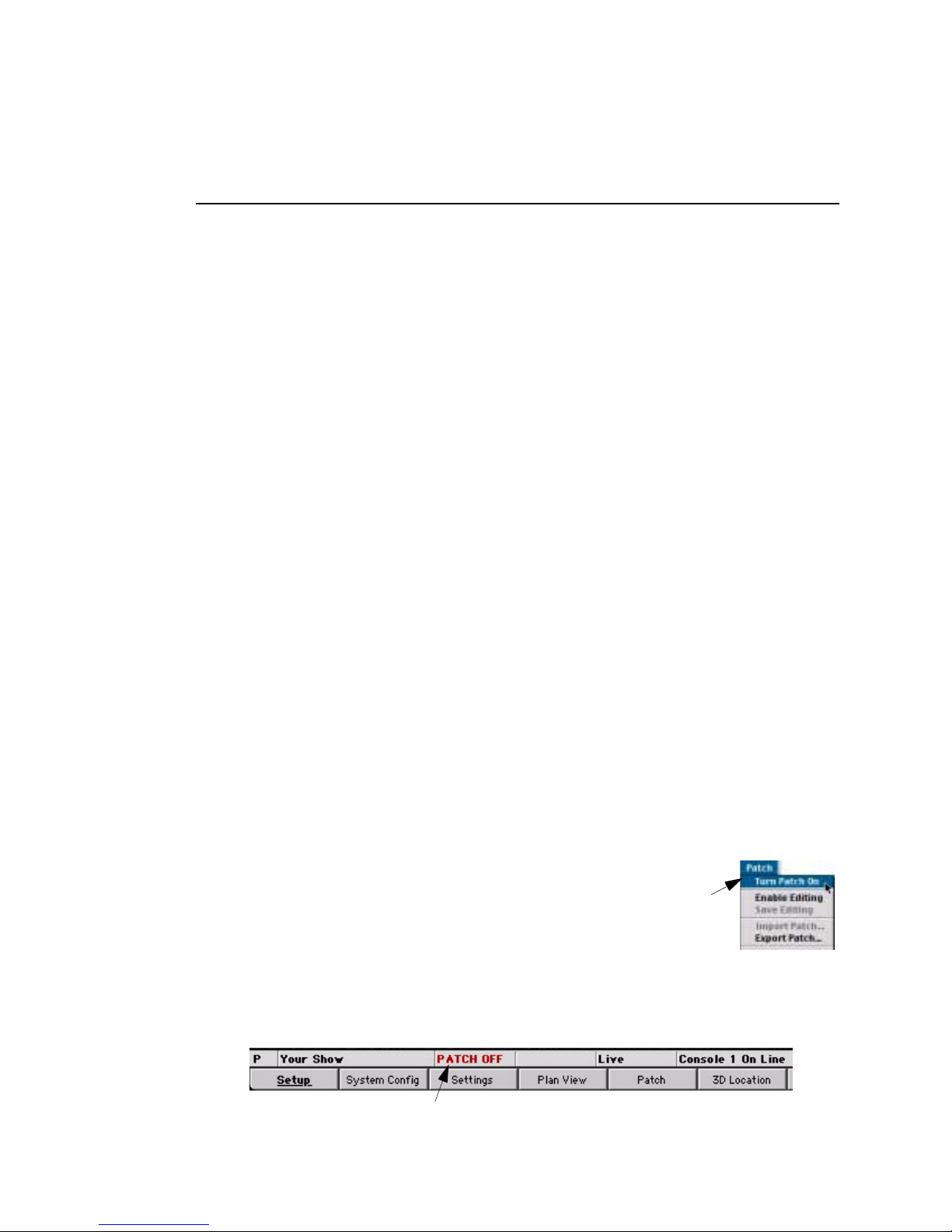
VARI❋LITE® - VIRTUOSO™ / VIRTUOSO™ DX CONSOLE USER’S MANUAL
Patch
Overview
Patching is the simplest way to manage the luminaires connected to the console. Patch
associates a single control channel with a single luminaire so that you can select one
channel at the console and have control of all the luminaire’s parameters (intensity,
color, beam, etc.). The patch operates by creating a look-up table that the console uses
to translate a luminaire’s associated thumbwheel address(es) into a single control
channel.
DMX Fixtures
DMX fixtures must be patched to the Virtuoso DX console using a profile in order to
be controlled. Patching connects the fixture to a DMX universe and allows its
thumbwheel address to be associated to a control channel. A DMX profile includes
the number of DMX channels required to operate a fixture and parameter mapping for
console control. Patching any fixture to the Virtuoso DX console requires a
thumbwheel address. The address is not a setting made at the fixture, but must be
included and must not be used by any other device in the system . This enables fixtures
to be accessed in PATCH OFF mode.
VARI❋❋❋❋LITE Series 300 Luminaires
VARI❋LITE Series 300 luminaires are patched directly by their thumbwheel address.
This address is determined by the port connection at the Smart Repeater™ unit. The
patch logically associates the "soft" thumbwheel address to the control channel.
Luminaire lamp power may be controlled by the SPC-36 interface. In this case, the
patch combines the thumbwheel from the Smart Repeater unit and the corresponding
thumbwheel from the SPC-36 interface to enable start, douse and standby lamp
functions, as well as, all parameter controls when the luminaire’s control channel is
selected.
Patch ON
Patch ON is the default setting when opening a
new show file. Patch must be turned on for
channel selection to operate by channel number
If patch is turned off,
select “Turn Patch On”
to enable patch again.
instead of thumbwheel address. The Patch ON
setting is available at the Patch menu.
The patch indicator lets you know whether patch is currently on or off.
32 1 6-Apr-02 02.9651.0001B
Patch Indicator
Page 59
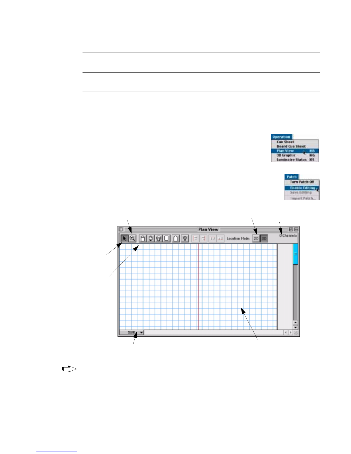
POWER-UP AND PATCH : PATCH
3
Note: PATCH OFF will not allow control of DMX luminaires that have not been
patched into the show file.
Setting Up Plan View Window
Devices are patched using the Plan View window. The Plan View appearance can be
set up as required.
To setup plan view window:
Step 1. At Operation menu, select Plan View. Plan View
window will open and 2D Display menu will become
available on menu bar.
Step 2. At Patch menu, select Enable Editing. Icon bar and grid
will appear in Plan View window and Patch menu selection
will change to “Disable Editing”. “Save Editing” option
will also be activated.
Displays as 2D or 3D
Zoom Control
configuration in window *
Total Channels
Tip
Select
Object
Icon Bar
Use pop-up menu to select zoom in or out percent
* Refer to “2D/3D Mode Guidelines” on page 47 for more information.
Grid line
(based on Grid Spacing)
You can periodically save editing changes to the Plan View without disabling editing,
by selecting Save Editing at the Patch menu.
02.9651.0001B 16-Apr-02 33
Page 60
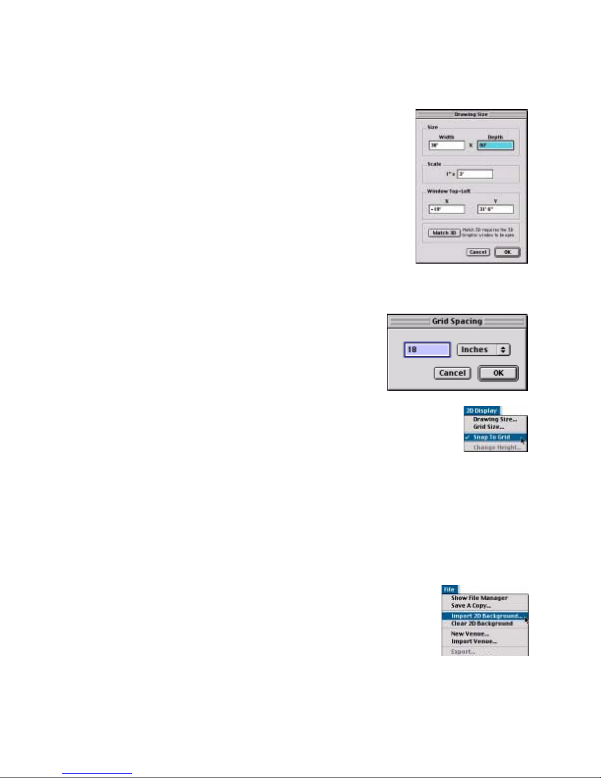
VARI❋LITE® - VIRTUOSO™ / VIRTUOSO™ DX CONSOLE USER’S MANUAL
Step 3. If required, define plan view drawing size:
a. At 2D Display menu, select Drawing Size...
Drawing Size window will open.
b. Enter size, scale, and point of origin (X/Y
coordinate) for drawing (refer to “Match 3D”
on page 273 for instructions on using this
feature). (The default unit of measure is
English. To configure console for Metric
units, refer to “Settings Window” on
page 258.)
c. Click Ok.
Step 4. If required, define grid size (spacing between
grids):
a. At 2D Display menu, select Grid Size...
Grid Spacing window will open.
b. Enter grid spacing and select inches or
feet at pop-up menu. (The default unit
of measure is English. To configure
console for Metric units, refer to
“Settings Window” on page 258.)
c. Click Ok.
d. At 2D Display menu, enable or disable Snap To Grid
option (enabled when checked).
Step 5. Display luminaire icons in a two-dimensional or three-
dimensional location mode by clicking on either 2D or 3D. Refer to “2D/3D
Mode Guidelines” on page 47 for important information regarding this
feature.
Plan View Background Picture
A 2D background picture can be imported for use in the Plan View window. The
console will accept the following 1:1 format files:
• *.dxf
• *.dwg
To import Plan View background picture:
•At File menu, select Import 2D Background...
34 1 6-Apr-02 02.9651.0001B
Page 61
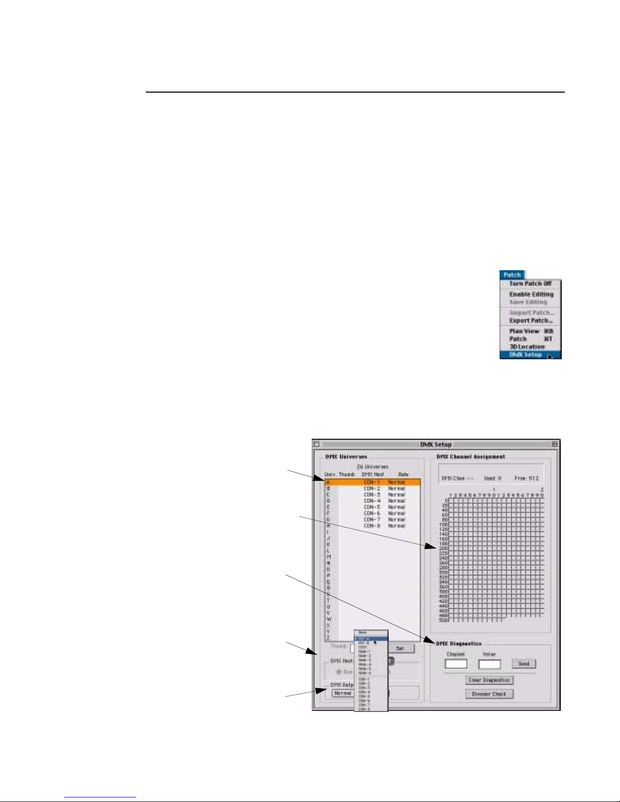
POWER-UP AND PATCH : PATCH
3
Patching DMX/Conventional Fixtures
The console provides for a maximum of 26 universes (labeled A thru Z), which are
assigned to DMX buses or "hosts" (hardware outputs within the system). This means
that the actual amount of buses available will depend on your system setup. The
V irtuoso DX console contains two DMX cards, each supporting four universes. Other
VARI❋LITE interfaces which include DMX buses are the UDM unit (one bus) and
the NIF unit (two buses). These buses and their starting thumbwheel addresses can be
configured using the DMX Setup window. The DMX Setup Window opens with a
default of eight universes, however, the DMX Host contains a "None" option to clear
this configuration.
To define DMX universes:
Step 1. If necessary, at Patch menu, select Enable Editing. (Must
be enabled to edit window.)
Step 2. At Patch menu, select DMX Setup.
Step 3. For each required universe, do the following:
a. Using cursor, select universe by letter (A-Z).
b. Select DMX Host. (If NIF is selected, also select Bus A or B.)
c. For NIF or UDM units, enter thumbwheel address.
d. Click Set.
DMX Universe (A-Z) Must be assigned to a device
(UDM, NIF, etc.) by thumbwheel address
DMX channel assignments
for selected universe
For use with DMX
diagnostics feature *
Bus
Assignment
* For instructions on using DMX diagnostics, refer to “DMX Channel Tests” on page 297.
02.9651.0001B 16-Apr-02 35
DMX Output
Pop-up Menu
Page 62
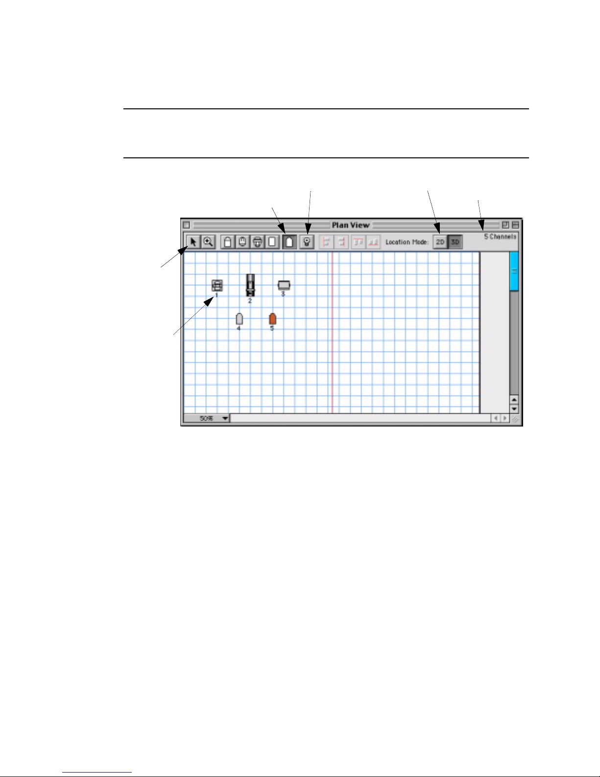
VARI❋LITE® - VIRTUOSO™ / VIRTUOSO™ DX CONSOLE USER’S MANUAL
To patch a DMX or conventional fixture:
Note: Depending on whether you are patching a generic DMX fixture or a conven-
tional fixture, a slightly different patch window will open when you drop the respective icon into the Plan View window.
Displays as 2D or 3D
DMX Fixture Icon
Conventional Fixture Icon
Select
Object
configuration in window *
Total Channels
Channel
Number
* Refer to “2D/3D Mode Guidelines” on page 47 for more information.
Step 1. At Plan View window icon bar, select either DMX or conventional fixture
icon as required.
Step 2. At desired location on plan view, click to place icon. Appropriate DMX or
Conventional Patch window will open.
Step 3. At DMX or Conventional Patch window, do the following:
a. At Device pop-up menu, specify fixture profile type.
b. At Address column, enter appropriate channel and thumbwheel informa-
tion.
c. At Lamp Control column, specify lamp source and preheat level as
required. (Preheat values of 0 to 9 percent may be assigned for incandescent luminaires.)
d. At Focus column, define any special focus instructions as required to
sync mirror fixtures for pan and tilt actions.
36 1 6-Apr-02 02.9651.0001B
Page 63
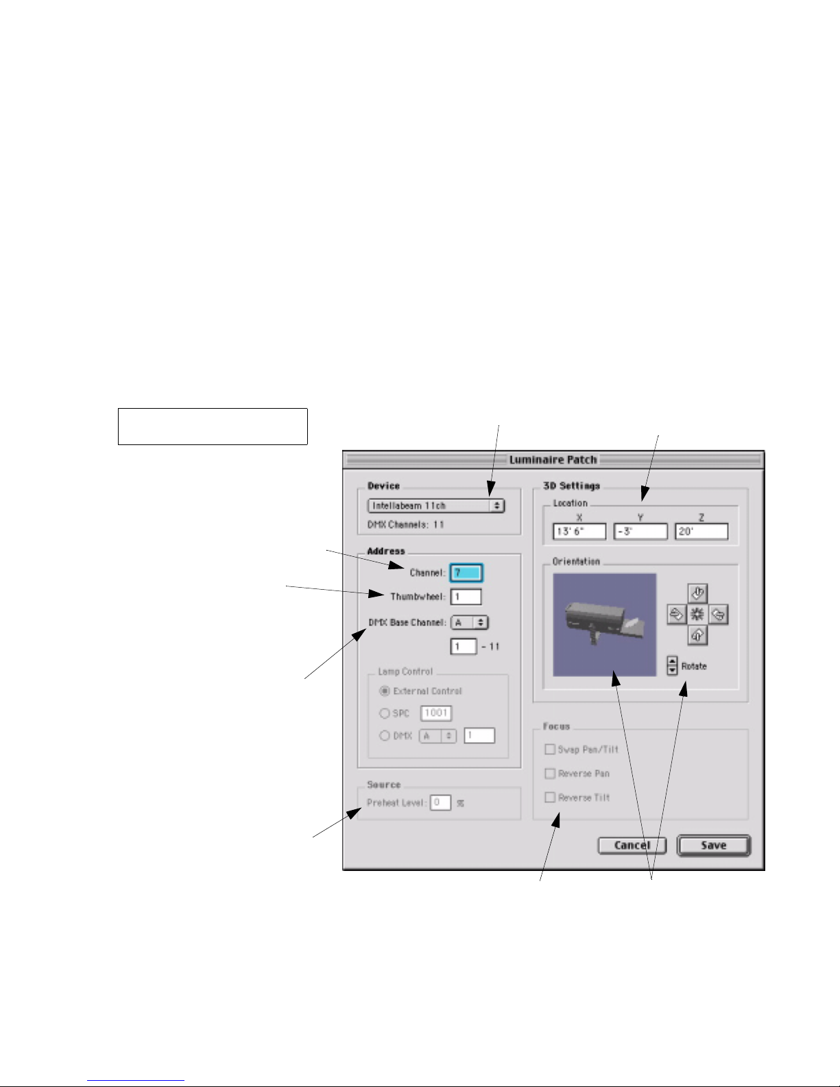
POWER-UP AND PATCH : PATCH
e. Do one of the following as required:
1) For automated luminaire s: use DMX Base Chan nel pop-up menu to
assign a DMX universe. Enter luminaire DMX starting address in
field beneath universe setting. (Ending address will be generated
according to profile used.)
2) For conventional luminaires: in DMX Address column, assign DMX
universe. Using range entry fields beneath display column; add,
change or remove addresses. (Left field is for single channel entry.)
T o add a scroller , click Add S croller box beneath device popup menu.
See page 39 for further instructions regarding scrollers.
3
(Refer to next page for snapshot
of Conventional Patch window)
Channel Assignment -
Channel which will control fixture
Thumbwheel Address -
Can be any number from
1-2000 as long as it does not
conflict with an existing address
Starting DMX Address
Typically the DMX fixture’s
thumbwheel setting
DMX Patch Window
Select Profile
Define 3D settings
or use defaults
Specify lamp control
source preheat level
(if required)
02.9651.0001B 16-Apr-02 37
Defines special focus inst ructions
(if available)
Position luminaire
Page 64
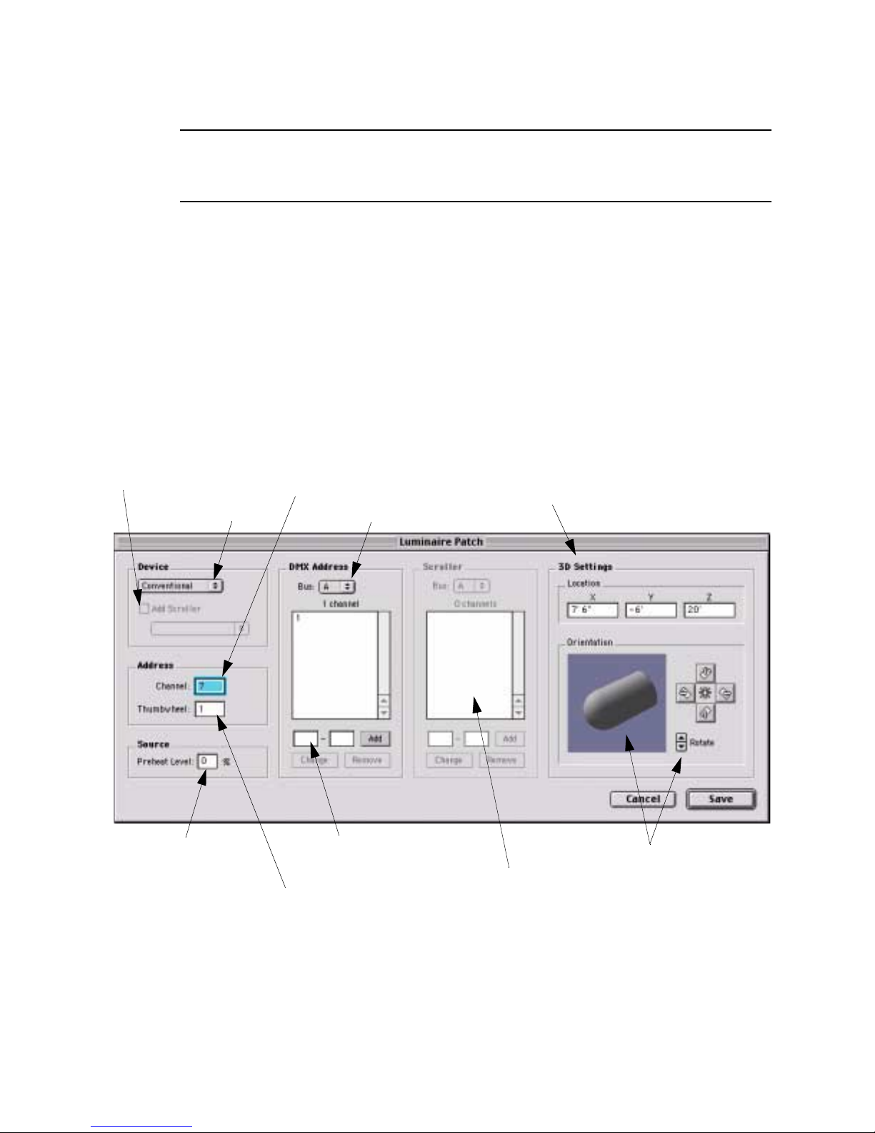
VARI❋LITE® - VIRTUOSO™ / VIRTUOSO™ DX CONSOLE USER’S MANUAL
Note: The next three steps are only required if you intend to use the console’s 3D
graphic features. For more information regarding these coordinates, refer to “Defining
X, Y, Z Locations” on page 274.
f. Use default 3D X, Y, and Z coordinates or enter new ones.
g. Use Position pop-up menu to specify luminaire orientation and location
(i.e. hanging, floor mount, stage left, etc.).
h. Use pointer or Rotate arrows to rotate luminaire to required position.
i. When finished, click Save.
Step 4. Repeat Steps 1-3 for each DMX luminaire in your system.
Step 5. When all luminaires are defined in your patch, at Patch menu, select
Disable Editing. (This prompts a dialog allowing you to save editing.)
Click “Add Scroller” to
highlight Scroller window
(see next page)
Select Profile
Channel Assignment -
Channel which will control fixture
Bus Choice
Define 3D settings
or use defaults
Conventional Patch Window
Specify lamp control
source preheat level
Thumbwhe el Address -
Can be any number from
1-2000 as long as it does not
conflict with an existing address
38 1 6-Apr-02 02.9651.0001B
Define channel range
Position luminaire
Click “Add Scroller” to
highlight Scroller window
(see next page)
Page 65
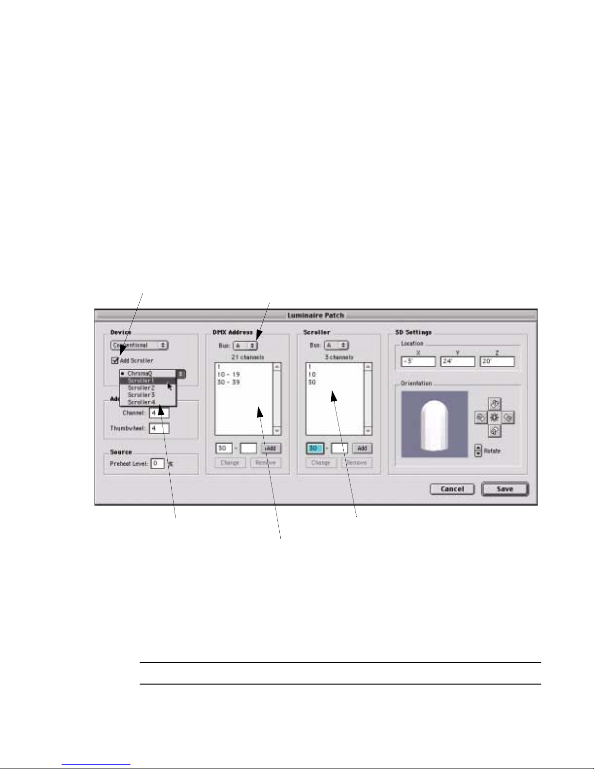
To add a scroller:
Step 1. To add a scroller, click Add Scroller box beneath device popup menu.
Step 2. At Scroller popup menu, select a scroller type in order to define which gel
string it will reference (see below).
Step 3. In DMX Address column, select a DMX bus. Using range entry fields
beneath column; add, change or remove addresses. These addresses will
define which DMX channels control scroller intensity.
Step 4. In Scroller column, select a DMX bus. Using range entry fields beneath
column, add, change or remove addresses. These addresses will define which
channels control scroller color.
Click “Add Scroller” to
highlight Scroller window
Bus Choice (if applicable)
POWER-UP AND PATCH : PATCH
3
Conventional Patch Window
Select scroller type to define its gel string
Scroller Types
Five scroller type choic es are provide d in order to allow d iffe rent scrollers to reference
different gel strings.
• ChromaQ - Type of scroller which supports 3D colors for the standard gel string.
Supports 16 frames.
• Scrollers 1-4 - Four additional generic scroller types.
Note: Scroller color control is controlled by the Wheel encoder.
02.9651.0001B 16-Apr-02 39
Define channels for color control
Define channels for intensity control
Page 66
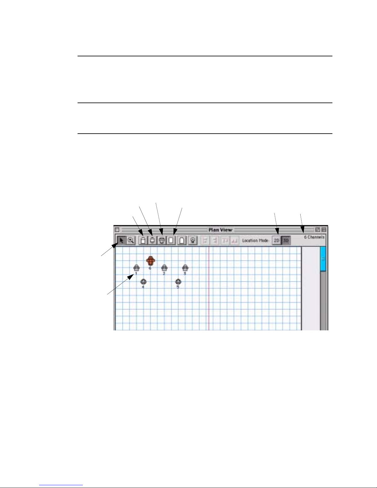
VARI❋LITE® - VIRTUOSO™ / VIRTUOSO™ DX CONSOLE USER’S MANUAL
Patching VARI❋LITE Series 300 Luminaires
Use this procedure to patch VARI❋LITE interface devices, Series 300 luminaires, and
lamp power supplies.
Note: This patch procedure does not work for VL2000™, VL2™ or VL4™
luminaires. Series 200™ luminaires must be patched using the DMX procedure.
Refer to “Patching DMX/Conventional Fixtures” on page 35.
Step 1. At Plan View window icon bar, select a VARI❋LITE luminaire icon as
required.
Step 2. At desired location on plan view, click to place icon. Luminaire Patch
window will open.
VL6 Icon
VL5 Icon
Select
Object
Channel
Number
* Refer to “2D/3D Mode Guidelines” on page 47 for more information.
VL7 Icon
VLM Icon
Displays as 2D or 3D
configuration in window*
Step 3. At luminaire Patch window, do the following:
a. At Device pop-up menu, specify luminaire profile type (VL5™,
VL5Arc™, VL5B™, VL6™, VL7™, etc.).
Total Channels
b. At Address column, enter appropriate channel, thumbwheel, and bulb
thumbwheel information. (Thumbwheel addresses can be obtained from
the System Configuration window if necessary.)
c. Specify lamp source and preheat level as required. (Preheat values of 0
to 9 percent may be assigned for incandescent luminaires).
40 1 6-Apr-02 02.9651.0001B
Page 67
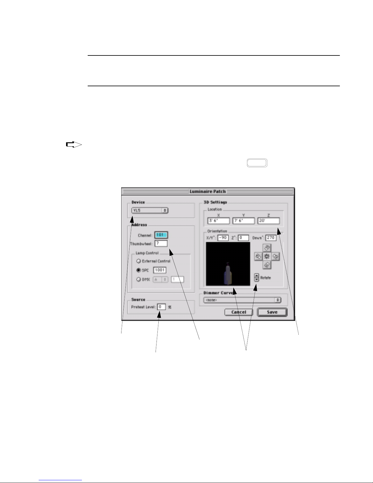
POWER-UP AND PATCH : PATCH
3
Note: The following three steps are only required if you intend to use the console’s
3D graphic features. For more information regarding these coordinates, refer to
“Defining X, Y, Z Locations” on page 274.
d. Use default 3D X, Y, and Z coordinates or enter new ones.
e. Use Position pop-up menu to specify luminaire orientation and location
(i.e. hanging, floor mount, stage left, etc.).
f. Use pointer or Rotate arrows to rotate luminaire to required position.
Tip
After the first luminaire’s icon has been placed and its information defined in the
Luminaire Patch window, you can place multiple icons without having the luminaire
patch window open each time. To do this, hold down while dropping icons.
Option
g. When finished, click Save.
Select Profile
(VL5Arc, etc.)
Step 4. Repeat Steps 1-3 for each VARI❋LITE luminaire in your system.
Step 5. When all luminaires are defined in your patch, at Patch menu, select
Disable Editing. (This prompts a dialog allowing you to save editing.)
02.9651.0001B 16-Apr-02 41
Define patch data
Specify lamp control
source and preheat level
Define 3D settings
or use defaults
Position luminaire
Page 68
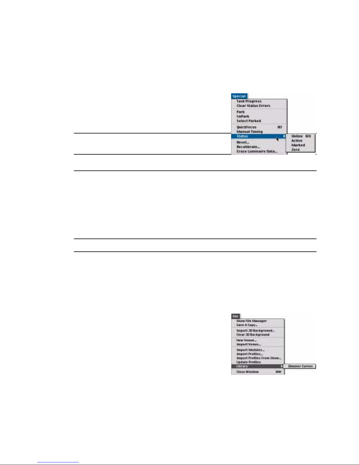
VARI❋LITE® - VIRTUOSO™ / VIRTUOSO™ DX CONSOLE USER’S MANUAL
Check online status:
Verify that the patch is correct by checking the online status of your luminaires. Any
channel that is up and running, communicating, patched, and has all of its show data is
considered online.
Step 1. Press [Online]. All online luminaires will
light in Channel Select window or Channel
Select panel (if available).
Step 2. Press [Online] again to exit status mode.
Note: This can also be done using the menu
command.
Dimmer Curves
Overview
Dimmer curves provide better control of incandescent source luminaires. There are
seven pre-programmed dimmer curves available: Fast Bottom, Fast Top, Full at 1%,
Hot Patch, IES Square Law, Slow Bottom, and Slow Top.
Note: Dimmer curves can also be edited from Luminaire Patch and Patch windows.
Dimmer Curves Window
The Dimmer Curves window allows import, export, updating, and deleting of dimmer
curves. Dates of dimmer curve files are shown for the console and for the show file.
They may be copied easily from the show file to the console, or from the console to the
show file.
To open Dimmer Curves window:
Step 1. Select Libraries/Dimmer Curves from the
File menu.
To move dimmer curve files:
Step 1. At Dimmer Curve window, using trackpad,
select dimmer curve to be moved.
Step 2. Click on Copy Direction column between
Console and Show File column. This column will change from a Bullet, to
left arrow, o r a right arrow. Keep clicking until desired direction is displayed.
42 1 6-Apr-02 02.9651.0001B
Page 69
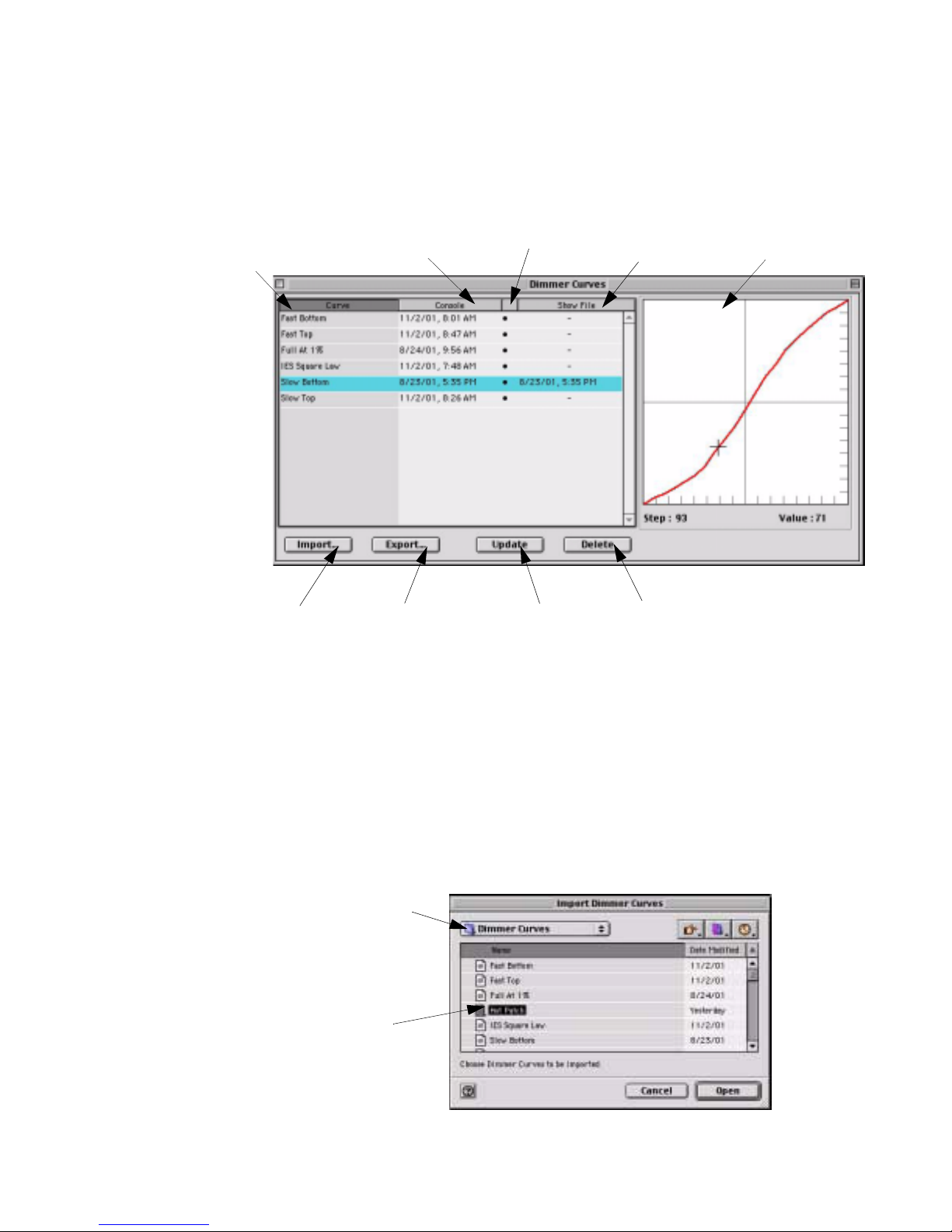
POWER-UP AND PATCH : PATCH
Step 3. To move file in the direction selected, click Update at bottom of window.
This will copy the file in the direction selected. (This is a permanent change.)
Copy Direction Column
Dimmer Curve
Name
Console
Date/Time
Clicking in column
toggles to arrows.
Show File
Date/Time
Dimmer Curve
Graph
3
Imports Files
From
Exports Files
To
Updates
Files
Deletes Selected
Dimmer Curve
To import dimmer curve files:
New dimmer curve files can be imported into the dimmer curves window. Any
comma-delimited file can be used as a dimmer curve file. A dimmer curve file can be
created in any text or spreadsheet program. The file must contain intensity values for
each step (0-255) separated by commas. For example, entries in a dimmer curve file
look like: 0,0,1,1,2,3....
Step 1. At Dimmer Curve window, click Import.
Step 2. At Import Data window, select file location (disk or folder). Click on file
name. Click Open.
File Location
File Name
02.9651.0001B 16-Apr-02 43
Page 70
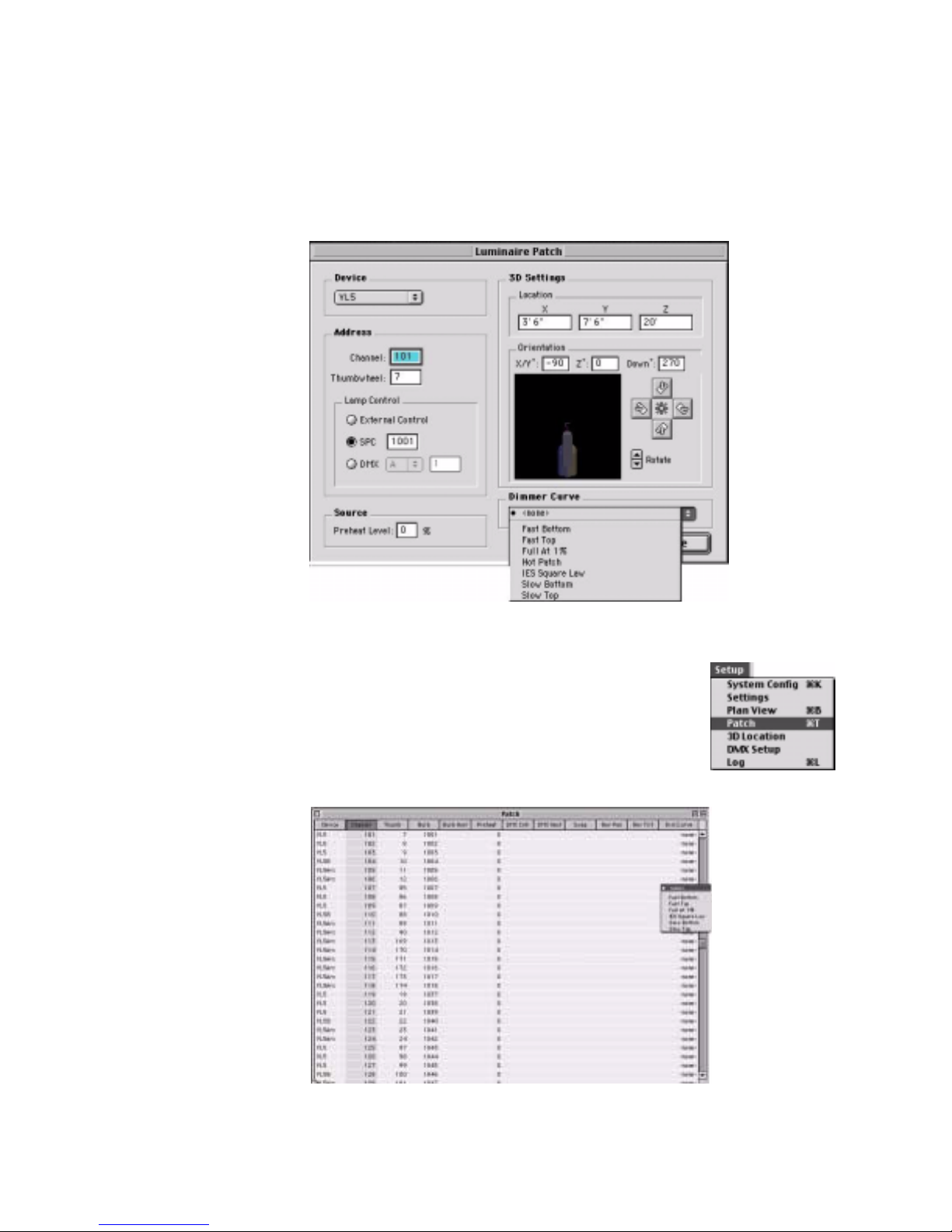
VARI❋LITE® - VIRTUOSO™ / VIRTUOSO™ DX CONSOLE USER’S MANUAL
To set dimmer curve from Luminaire Patch Window:
Step 1. At Luminaire Patch window, select desired dimmer curve.
Step 2. Click Save to update patch.
To set dimmer curve from Patch window:
Step 1. At Setup menu, select Patch. Window will open.
Step 2. For desired luminaire, click in Dim Curve column.
Step 3. At drop-down menu, select dimmer curve type.
44 1 6-Apr-02 02.9651.0001B
Page 71
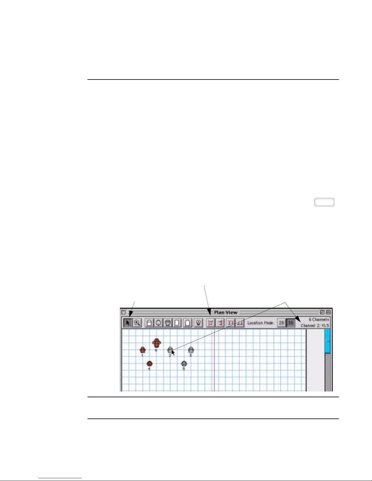
Patch Editing
Editing Windows
Once entered, patch data can be edited at the Plan View window or Patch window.
Save changes by selecting Save Editing or Disable Editing at the Patch menu.
Plan View
Depending on whether Patch Editing is enabled, the Plan View window will be
displayed differently.
With Patch Editing Enabled:
• Move icons to new locations with the selection tool (while holding down the
trackpad button).
POWER-UP AND PATCH : PATCH EDITING
3
• Select multiple icons by dragging a box around them or by holding down
button while selecting.
• Double-click any icon to bring up its associated patch data window.
• Change the 3D height location (Z coordinate) of selected luminaires. Refer to
“Changing 3D Height Location” on page 275.
• Delete icons using the alpha keyboard.
Align Tools - Available when
multiple icons are selected
Selection Tool - Use to select, move,
and open information window for icons
Displays fixture information when
pointer is placed over an icon
Shift
Note: Selections made in the Plan View window while editing is Enabled will not be
reflected at Channel Select window or optional Channel Select panel.
02.9651.0001B 16-Apr-02 45
Page 72
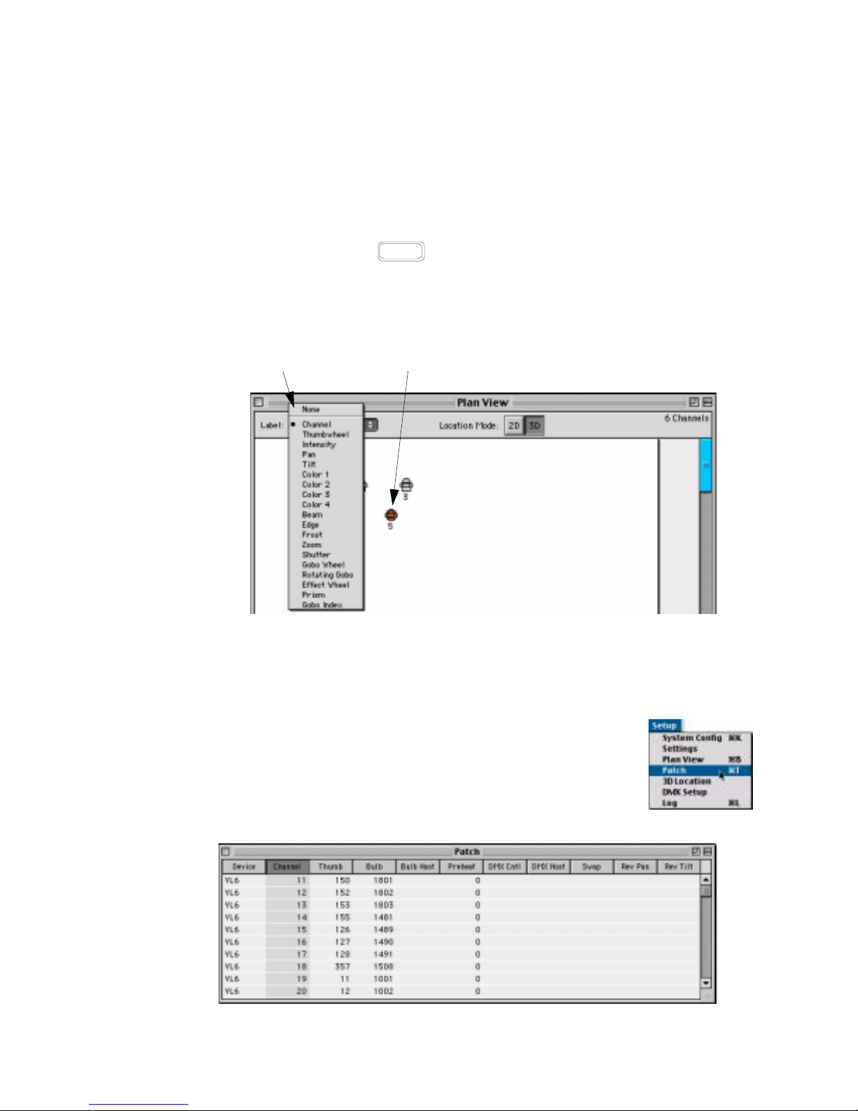
VARI❋LITE® - VIRTUOSO™ / VIRTUOSO™ DX CONSOLE USER’S MANUAL
With Patch Editing Disabled
• Use View Select pop-up menu to view status data based on channel, thumbwheel,
or any other parameter data as required. For example, selecting Pan would
display the pan coordinate for each luminaire.
• Select icons by clicking on them. Select multiple icons by dragging a box around
them or by holding down button while selecting.
Shift
• Selected icons (channels) in the Plan V iew window (while edi ting is Disabled) will
also be selected for manual control at the Channel Select panel. Refer to
“Selecting Channels” on page 50. Click in an open space to deselect all icons.
View Select
Pop-Up Menu
Selected icons (channels) will be
reflected on the Channel Select panel
Patch
The Patch window displays patch information in a spreadsheet format. Data can be
viewed at any time and edited when patch editing is enabled.
•At Setup menu, select Patch. Window will open.
• View and/or edit information as required using cursor and
alpha-numeric keyboard.
• Click on a column heading block to sort information by that
type.
46 1 6-Apr-02 02.9651.0001B
Page 73
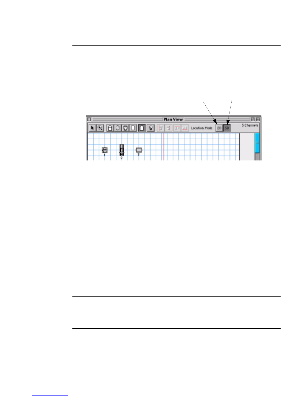
POWER-UP AND PATCH : PATCH EDITING
2D/3D Mode Guidelines
The relationship between the 2D and 3D modes are important to understand when
placing icons and editing in the Plan View window.
3
2D Mode Locates luminaires
by X and Y coordinates
The 2D mode provides an X and Y coordinate for each luminaire (icon) to locate it in
relation to a 2D scheme. The 3D mode provides an additional coordinate, Z, in
addition to X and Y to locate a luminaire in relation to a 3D scheme (refer to “Defining
X, Y, Z Locations” on page 274 for more information on the console’s 3D Graphic
features). The relationship between these modes is as follows:
• When an icon is initially placed while in 2D mode, its default X and Y coordinates
are provided to its 3D location as well. In other words, X and Y for 2D and 3D are
the same when an icon is first dropped. (They are considered “linked” at this
point.) A default Z (height) value of 20 feet is also included in the 3D location
data for the luminaire.
3D Mode Locates lumi naires by
X, Y, and Z coordinates
• If an icon is moved in the Plan View while in 2D mode, the X and Y coordinates
would be updated in its 2D patch information, but not in the 3D patch. The 3D X
and Y coordinates would still be the default values (given that the icon has not
previously been moved while in 3D mode). (The “link” is considered broken at
this point.)
General Rule. Modifying icon positions in the 2D mode will not be reflected in the
3D patch. Modifying icon positions in the 3D mode will be reflected in the 2D patch.
Note: The Match 3D feature available in the Drawing Size window allows importing
of the size and window positioning coordinates from the 3D graphic into the Plan
View. (This requires that a 3D graphic has been previously imported.) Refer to
“Match 3D” on page 273.
02.9651.0001B 16-Apr-02 47
Page 74

VARI❋LITE® - VIRTUOSO™ / VIRTUOSO™ DX CONSOLE USER’S MANUAL
Notes
48 1 6-Apr-02 02.9651.0001B
Page 75

CHAPTER 4.
Manual Control
Manual Control
Manual ControlManual Control
This chapter provides instructions for controlling luminaires in order to build cues.
• Channel Select
• Lamp Control
• Encoder Control
• Keypad Control
• Luminaire Status
Note: The Select Displays feature is also used for manual control of luminaires,
however, due to the versatility of this feature it is covered in a separate chapter.
02.9651.0001 C 23-Sep-02 49
Page 76

VARI❋LITE® - VIRTUOSO™ / VIRTUOSO™ DX CONSOLE USER’S MANUAL
Channel Select
Overview
When the patch was defined in the previous chapter, each luminaire was assigned to a
control channel. Selecting the channel will give you control of the luminaire’s
parameters in order to build cues or to store as groups of channels.
If the patch is disabled, luminaires must be selected for manual control using their
thumbwheel address. The procedure for selecting a thumbwheel address is the same
as channel selection. (For example, the procedure for selecting channel 301 would be
the same as the procedure for selecting thumbwheel 301.)
Note: W e recommend using Patch Disabled m ode only when VARI❋LITE luminaires
are present. This is not a recommended state for storing cues, presets, groups, etc.
In addition to the methods of channel selection covered in this section, channels can
also be selected in the Plan View and 3D Graphic windows. However, these methods
are covered along with the respective topics elsewhere in this manual:
• For selecting channels via the Plan View window, refer to “Plan View” on
page 45.
• For selecting channels via the 3D Graphic window, refer to “Using 3D Graphic
Window” on page 276.
Selecting Channels
Channel numbers (patch enabled) or thumbwheel numbers (patch disabled) can be
selected or deselected from the Channel Select window, command-line keypad, and/or
Channel Select panel. When selecting channels, the channels will light in the window
on the Channel Select panel and their respective icons will be highlighted in the Plan
View window.
50 23-Sep-0 2 02.9651.0001 C
Page 77
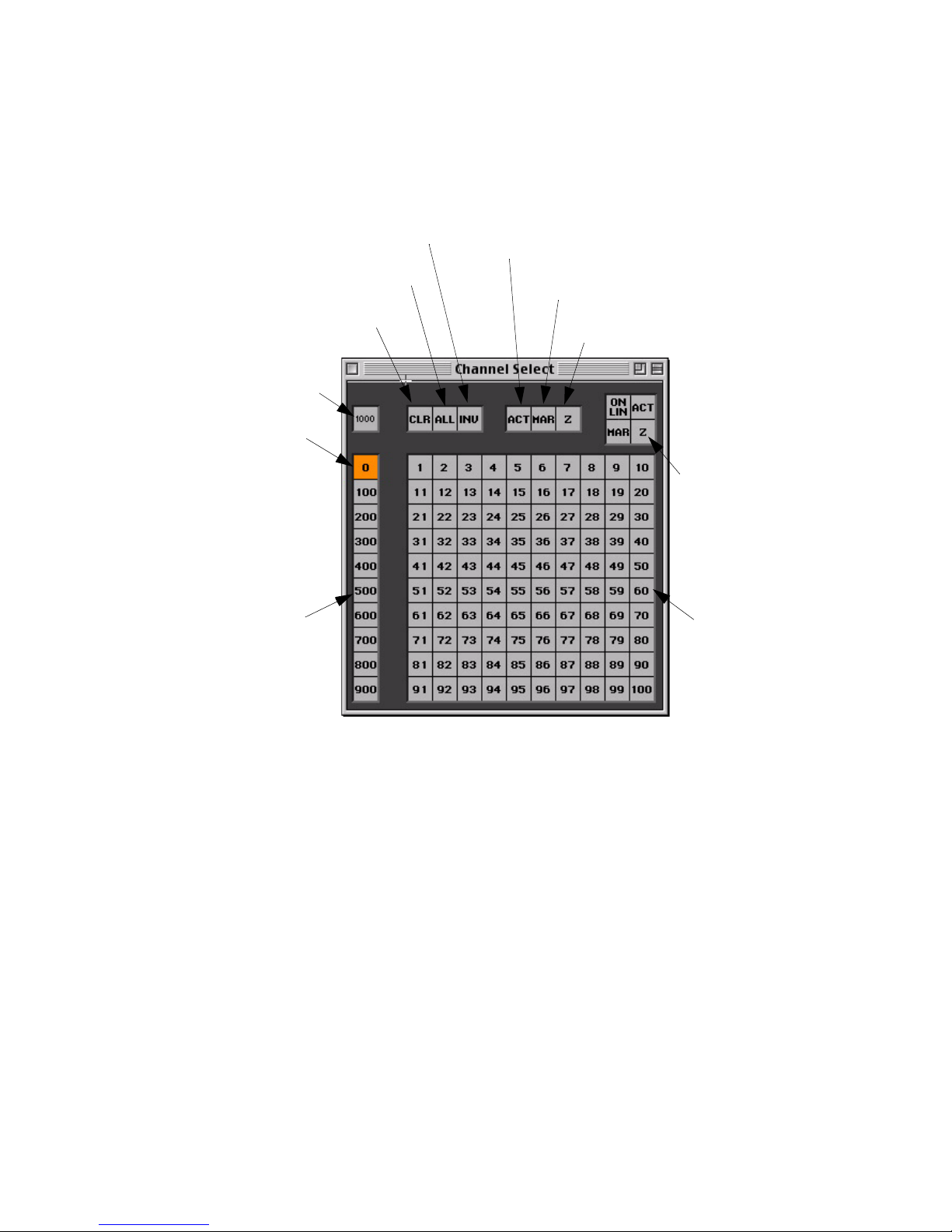
From Channel Select Window
Open window by selecting Channel Select at the Windows menu.
Deselects current channels and
selects all other patched channels
Clears all
channel selections
Millennium Button Routes control to first 1000
channels when not active
or second 1000 when active
Selected button
Selects all
patched channels
MANUAL CONTROL : CHANNEL SELECT
4
Selects all
active channels
Selects all channels
which are in a marked state
Selects all channels
which are in a zero state
Status Mimic Buttons Highligh t buttons of
channels in online, active,
marked, or zero status states
(does not select channels)
Century Buttons (0-900) Routes the 100-button array
to one of ten pages
Select a single channel (or multiple single channels):
Step 1. Using cursor, click [1000] as required.
Step 2. Click [0] through [900] as required. Button will light.
Step 3. Click button of channel number to be selected. Button will light.
Step 4. To select multiple single channels, continue clicking on buttons of channel
numbers you wish to add (selections “pile on”).
Example: T o select channel 521, ensure that [1000] button is not active, click
the page [500] button and then click [21] on the 100-button array.
Select a range of channels:
Step 1. Using cursor, click [1000] as required.
Step 2. Click [0] through [900] as required. Button will light.
100-Button Array Represents a group
of 100 channels as
determined by the
millennium and century
buttons
Step 3. Click button of first channel number to be selected. Then, while holding
mouse button, drag across range of channels.
02.9651.0001 C 23-Sep-02 51
Page 78
VARI❋LITE® - VIRTUOSO™ / VIRTUOSO™ DX CONSOLE USER’S MANUAL
Select channels on multiple pages:
Step 1. Using cursor, click [1000] as required.
Step 2. Click [0] through [900] as required. Button will light.
Step 3. Select required channels.
Step 4. Click on next required page ([0] through [900]). First page button will be
dimly highlighted to show that channels are selected on that page.
Step 5. Select required channels on new page.
Step 6. Repeat Steps 4 and 5 as required.
Deselect channels:
• Press any selected channel button(s) to deselect.
Special Buttons
Six buttons are available in the Channel Select window for simplifying channel
selection.
CLR ALL
INV ACT
MAR Z
• [CLR] - clears all channel selections.
• [ALL] - selects all patched channels.
• [INV] - (Invert) deselects currently selected channels and selects all other patched
channels.
• [ACT] - selects all channels with active* luminaires.
• [MAR] - selects all marked* channels.
• [Z] - selects all channels in a zero* state.
* Active - luminaires with intensity greater than zero (1-100%).
* Marked - luminaires with an intensity state of “marked.”
* Zero - luminaires with an intensity state of zero ("hard zero", 0% level).
(For a more in-depth explanation, refer to “Inten sity States” on page 117).
52 23-Sep-0 2 02.9651.0001 C
Page 79
MANUAL CONTROL : CHANNEL SELECT
4
Status Mimic
These four buttons located at the top right portion of the Channel Select window are
referred to as “status mimic” buttons. Here cha nnel selec t buttons i lluminate in purple
as an indicator rather than as a selection tool.
ON
ACT
LIN
MAR Z
[On Lin] - Indicates all online luminaires.
[Act] - Indicates all luminaires that are active*.
[Mar] - Indicates all luminaires that are marked*.
[Z] - Indicates all luminaires that are in a zero* state.
* Active - luminaires with intensity greater than zero (1-100%).
* Marked - luminaires with an intensity state of “marked.”
* Zero - luminaires with an intensity state of zero ("hard zero", 0% level).
(For a more in-depth explanation, refer to “Intensity States” on page 117).
Fr om Ke ypa d
Channel selection guidelines:
• Any combinations of [ + ], [ - ], and [Thru] are allowed.
• Thru lists (channel ranges) must be entered in ascending order only.
• [Enter] terminates the selection process and sets the keypad so that the next entry
is automatically accepted (pressing [Clear] to reset the command-line keypad is
not required.)
• Because the keypad always defaults to channel entry mode, use of the [Chan]
(channel) button is optional.
FE
I
CG
ready (channel)
B
Select a single channel:
• <Chan> [ n ] [Enter].
Select multiple channels:
• <Chan> [m] [+] [n] [Enter].
Select a range of channels:
• <Chan> [ m ] [ Thru ] [ q ] [Enter].
Other examples:
• <Chan> [ m ] [ + ] [ s ] [ Thru ] [ w ] [Enter].
• <Chan> [ m ] [ + ] [ s ] [ Thru ] [ w] [ - ] [t ] [Enter].
02.9651.0001 C 23-Sep-02 53
Page 80
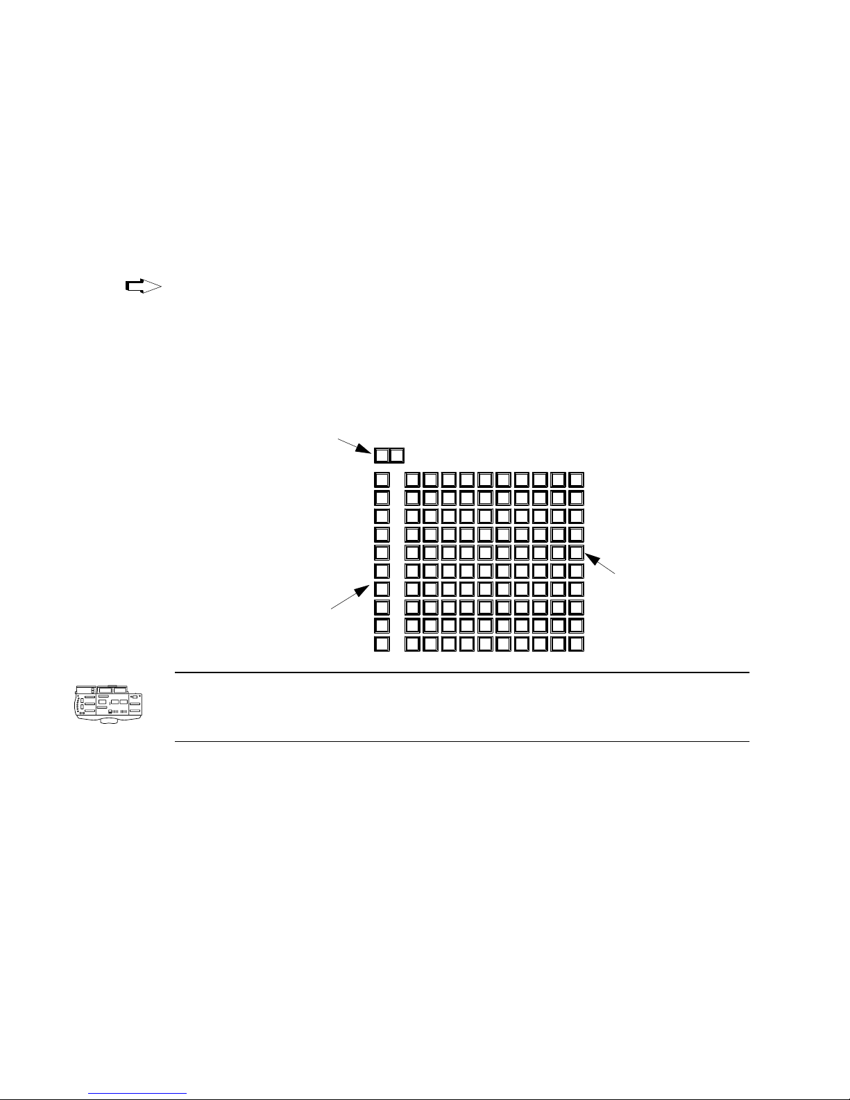
VARI❋LITE® - VIRTUOSO™ / VIRTUOSO™ DX CONSOLE USER’S MANUAL
[Clear]
[Clear] functions as a backspace key when used during command-line construction.
For example, <Chan> [n] [Thru] [t] [Clear] [s] [Enter] results in the selection of
channels n thru s. When [Clear] is used after an [Enter] (fully terminated command
line), the command line is cleared.
The only thing that clears a syntax error on the command line is [Clear]. Any other
keypad entry is ignored until the error condition is cleared.
Shortcut
Holding down [Clear] will clear an entire unterminated command line.
From Channel Select Panel
Selecting channels from the C hannel Select panel (i f availab le) is basically the same as
selecting channels in the Channel Select window.
Millennium Buttons "000" routes control to first
1000 channels
"1000" routes control to
second 1000 channels
(When lit, indicates range
selected)
Century Buttons (0-900) Routes the 100-button array
to one of ten pages
1000
000
0
100
200
300
400
500
600
700
800
900
122111
22
21
3231
42
41
5251
62
61
72
71
8281
9291 93
5
3
4
13
14 15616
23
24 253626
33
34 35
43
44 45
46
53
63
73 77
83
64 65
74 758676
84 85
94 95 96
56
66
7
17
27
37
47
5754 55
67
87
97
8
18
19 20
29 30
382839 40
48
49 50
58
59 60
68
69 70
79 80
887889 90
98 99 100
109
100-Button Array Represents a group
of 100 channels as
determined by the
millennium and century
buttons
Note: The Virtuoso console is not equipped with the [000] button. In this case, when
the [1000] button is inactive, the channel select routes control to channels 1-1000.
When the [1000] button is lit, control is routed to channels 1001-2000.
Select a single channel (or multiple single channels):
Step 1. Press [000] or [1000] as required.
Step 2. Press [0] through [900] as required. Button will light.
Step 3. Press button of channel number to be selected. Button will light.
Step 4. To select multiple single channels, continue selecting channels (channel
selections “pile on”).
Example:
To select channel 521, ensure that [000] button is not active, press the page
[500] button and then press [21] on the 100-button array.
54 23-Sep-0 2 02.9651.0001 C
Page 81

MANUAL CONTROL : CHANNEL SELECT
4
Select a range of channels:
Step 1. Press [000] or [1000] as required.
Step 2. Press [0] through [900] as required. Button will light.
Step 3. Press button of first channel number to be selected. Then, while holding
down first button, press button of last number in range. Fi rst and last buttons
will light, as will all those in-between.
Select channels on multiple pages:
Step 1. Press [000] or [1000] as required.
Step 2. Press [0] through [900] as required. Button will light.
Step 3. Press button of first channel number to be selected. Then, while holding
down first button, press button of last number in range. Fi rst and last buttons
will light, as will all those in-between.
Step 4. Press next required page ([0] through [900]). First page number button will
flash to show that channels are selected on that page.
Shortcut
Step 5. Press buttons for channels to be selected.
Step 6. Repeat Steps 3 through 5 as required.
Deselect a single channel (or multiple single channels):
• Press any selected channel button(s) to deselect.
Deselect a range of channels:
• Press button of first selected channel button to be deselected. Then, while holdi ng
down first button, press button of last number in range. The range will be
deselected.
To select a single channel and deselect all others, double-click on any channel button.
02.9651.0001 C 23-Sep-02 55
Page 82

VARI❋LITE® - VIRTUOSO™ / VIRTUOSO™ DX CONSOLE USER’S MANUAL
Channel Select Quick Buttons
Six special buttons are available for simplifying channel selection.
• [Invert] - deselects currently selected channels and selects all other patched
channels.
• [Clear] - clears all channel selections.
• [All] - selects all patched channels.
• [Active] - selects all channels with active* luminaires.
• [Mark] - selects all marked* channels.
• [Zero] - selects all channels in a zero* state.
* For a more in-depth explanation, refer to “Intensity States” on page 117.
[Next] and [Last]
The [Next] and [Last] buttons will step through all on-line channels.
Shortcut
[Next] - increments the channel selection by one.
If a single channel were selected (either with the keypad or the 100 button array),
pressing [Next] will increment the channel selection by one. If a range of channels is
selected, the first press of [Next] will select the first channel in that range. Subsequent
presses will increment the channel selection by one, but will not select a channel
outside the range.
[Last] - decrements channel selection by one.
If a single channel were selected (either with the keypad or the 100 button array),
pressing [Last] will decrement the channel selection by one. If a range of channels is
selected, the first press of [Last] will select the last channel in that range. Subsequent
presses will decrement the channel selection by one, but will not select a channel
outside the range.
[Next] / [Last] - pressing these buttons together will reselect the original channel
range.
56 23-Sep-0 2 02.9651.0001 C
Page 83
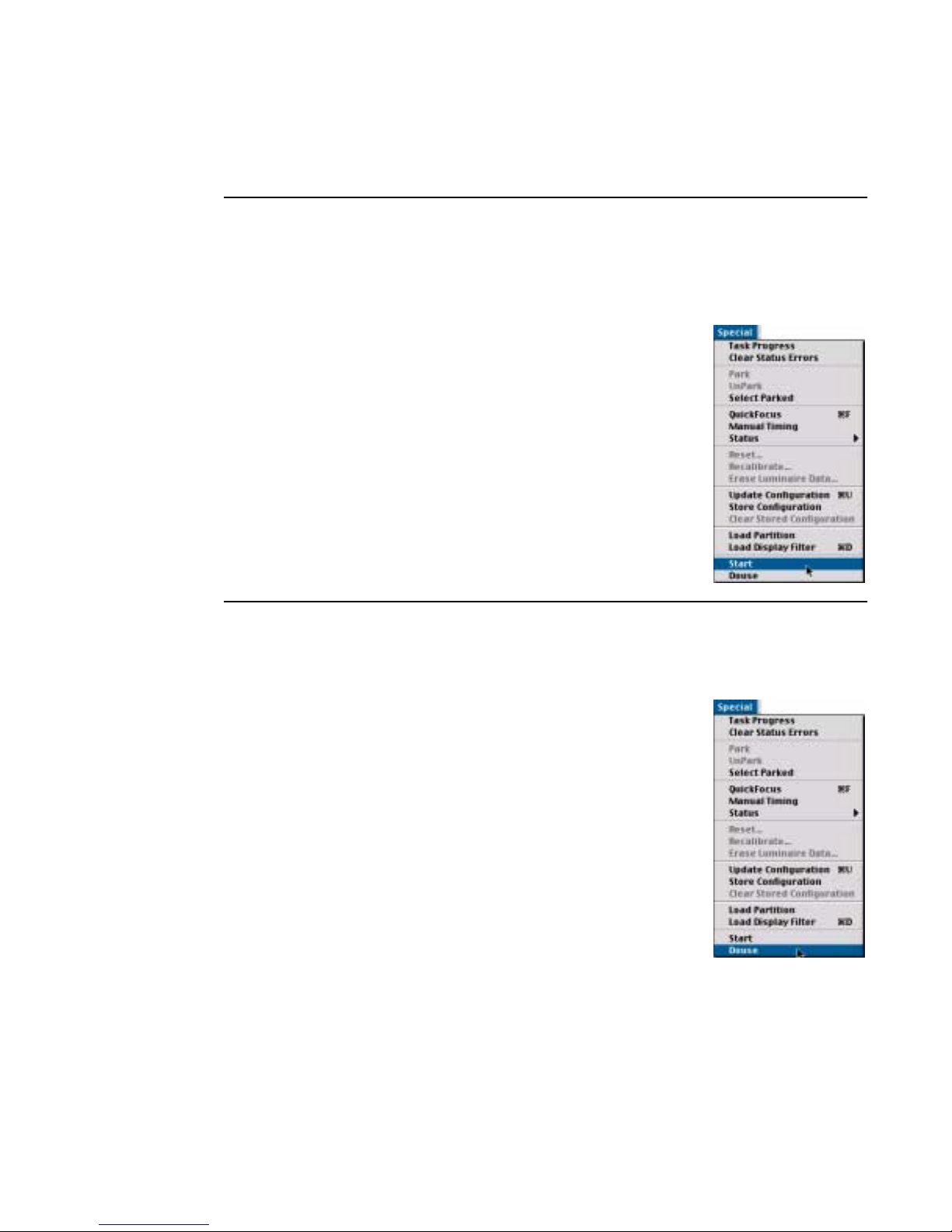
Lamp Control
Start
Start will function for all arc luminaires with remote start capability.
Start lamps using [Start] button:
Step 1. Select luminaire(s) for manual control.
Step 2. Set luminaire(s) in recommended starting position
according to manufacturer’s specifications.
Step 3. Press [Start].
Start lamps from menu bar:
Step 1. Select luminaire(s) for manual control.
Step 2. Set luminaire(s) in recommended starting position
according to manufacturer’s specifications.
MANUAL CONTROL : LAMP CONTROL
4
Step 3. At Special menu, select Start.
Douse
Douse will function for all arc luminaires with remote douse capability.
Douse lamps using [Douse] button:.
Step 1. Select luminaire(s) for manual control.
Step 2. Press [Arm] / [Douse].
Douse lamps from menu bar:
Step 1. Select luminaire(s) for manual control.
Step 2. At Special menu, select Douse.
02.9651.0001 C 23-Sep-02 57
Page 84
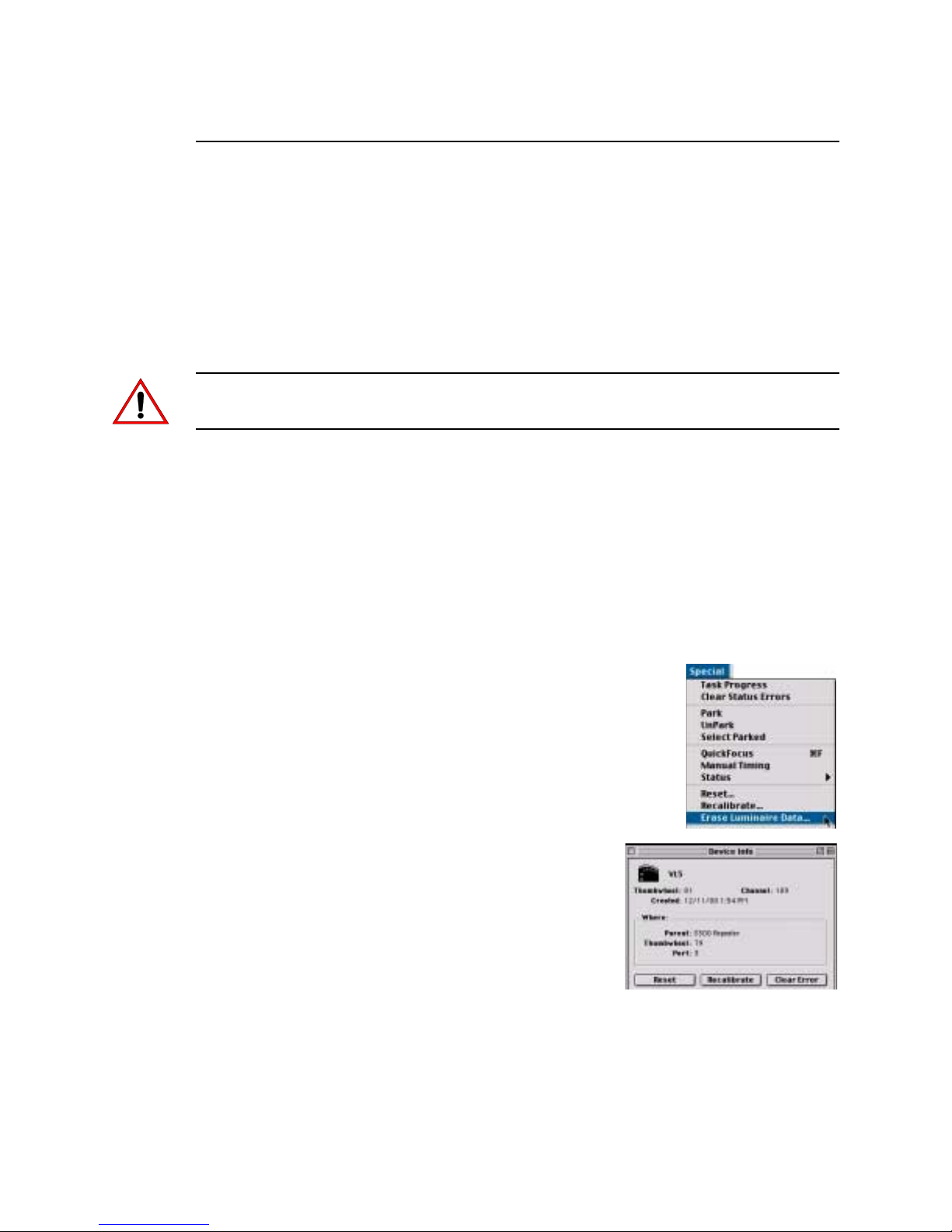
VARI❋LITE® - VIRTUOSO™ / VIRTUOSO™ DX CONSOLE USER’S MANUAL
Reset/Recalibration/Erase Luminaire Data
Two different types of luminaire resets are available.
• Recalibrate - returns luminaire to default home position based on profile and redownloads data.
• Reset - activates reset command if supported by luminaire and profile and redownloads data.
Erase Luminaire Data clears all data from a luminaire’s on-board RAM and disk.
CAUTION: Erase Luminaire Data command removes all show data from the show
file for selected channels. There is NO undo available.
Recalibrate luminaires using [Reset] button:
Step 1. Select luminaires for manual control.
Step 2. Press [Arm] / [Reset].
Reset luminaires using [Reset] button:
Step 1. Select luminaires for manual control.
Step 2. Press [Arm] / [Reset] [Reset] (press Reset button twice while holding down
Arm button).
Reset/Recalibrate/Erase Luminaire Data from menu bar:
Step 1. Select required channels.
Step 2. At Special menu, select Reset, Recalibrate, or
Erase Luminai r e Data.
Reset VARI❋LITE luminaires fr om System Configur ation
window:
Step 1. At System Configuration window , double-click
icon of luminaire to be reset or recalibrated.
Device Info window will open.
Step 2. Click Reset or Recalibrate as required.
58 23-Sep-0 2 02.9651.0001 C
Page 85

Encoder Control
Overview
The manual control encoders (or “knobs”) provide incremental control of luminaire
parameters.
Console Encoders
Pan, tilt, and intensity are provided with permanently assigned encoders, while the
remaining parameters are mapped to “soft encoders.” The soft encoders control a
variety of luminaire parameters depending on which function is currently selected. A
display associated with each soft encoder indicates its selected function.
Functions:
• Color - controls color functions such as CMY, RGB, wheels, flags, or color plates.
• Beam - controls edge, beam, zoom, frost, strobe, and prism.
MANUAL CONTROL : ENCODER CONTROL
4
• Image - controls static gobo, rotating gobo, spin, and effects.
• 3d - routes X, Y and Z coordinates for pan and tilt.
• Dynamics - modifies rate, size, and orientation of dynamic states.
• Frame - controls framing shutters.
By selecting a function, the soft encoders change to control the parameters of that
function. These functions are fixture specific when selecting single luminaire types. In
addition to the encoder, m inimum and maxi mum control buttons are provided to apply
a default setting to selected luminaires. Like the soft encoders, the functionality of
these buttons depends on the currently selected function. The min/max buttons are
initially programmed with a default console setting, but can be reprogrammed with
your own settings as required. Instructions for programming new settings can be
found in “Storing New Default Min/Max Settings” on page 64.
Encoders Window
An Encoders window is also available. The window functions just as the standard
encoders and also provides a visible display of currently selected cue or effect and
allows specification of a submaster for cue tracking.
Fan Function
A special fan function is also available to provide five different types of encoder
fanning styles. Refer to “Encoder Fan” on page 66.
02.9651.0001 C 23-Sep-02 59
Page 86
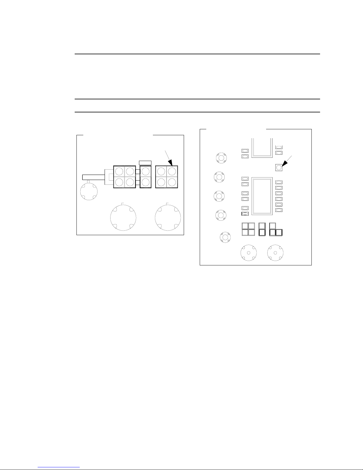
VARI❋LITE® - VIRTUOSO™ / VIRTUOSO™ DX CONSOLE USER’S MANUAL
Console Encoders
When a luminaire is selected for manual control, the encoders and buttons available on
the console’s front panel can be used to change its parameters.
Note: Additional functions can be accessed by pressing the [Shift] button.
Virtuoso DX Console
Virtuoso Console
[Shift]
Button
Intensity
[Shift] Button
Shutter
OpenFull Mark
Flip Shift
ZeroOut Close
Pan Tilt
Last Next
Pan and Tilt
Pan and tilt are controlled by the two encoders marked Pan and Tilt respectively.
These knobs can be used to change the position of a luminaire’s beam.
Three buttons above the Tilt encoder are also associated with pan and tilt functions:
• [Flip] causes selected luminaires to pan and tilt until the head is pointing in the
same direction as before. The head assembly pans 180 degrees and tilts as
required so that the head points in the same direction. (DMX moving mirror
luminaires will not respond to this command.)
• The [Next] and [Last] buttons will step through all on-line channels.
60 23-Sep-0 2 02.9651.0001 C
Page 87

MANUAL CONTROL : ENCODER CONTROL
4
Intensity
Intensity output can be controlled by the encoder marked Intensity. This knob can be
used to adjust the brightness of the luminaire’s beam. Six buttons to the right of the
Intensity encoder are also associated with the intensity function. (Intensity also affects
how a cue is stored, however, this topic will be discussed in more detail in “Intensity
States” on page 117.)
• [Full] sets selected luminaires to full intensity (100%).
• [Out] sets selected luminaires to an out* or inactive state (no parameter data, 0% level).
• [Mark] sets selected luminaires to a marked* state (0% level).
• [Zero] sets selected luminaires to zero* intensity (“hard zero”, 0%).
• Shutter [Open] is used with luminaire strobe or douser mechanisms.
• Shutter [Close] is used with luminaire strobe or douser mechanisms.
* For a more in-depth explanation, refer to “Intensity States” on page 117.
Color
Color can be controlled by the soft encoders when [Color] is selected. These knobs
can be used to adjust or change the hue and saturation of the beam’s color.
The soft encoders will be mapped as follows:
Encoder 1 - BLUE (open/cl ose)
Encoder 2 - AMBER (open/close)
Encoder 3 - MAGENTA (open/close)
Encoder 4 - WHEEL (open/close) - also controls gel scrollers.
w/ [Shift] button pressed - WHEEL SPIN (max/stop)
Encoder 5 - FROST (in/out)
Beam
Beam can be controlled by the soft encoders when [Beam] is selected. These knobs
can be used to set all the parameters associated with a luminaire’s beam.
The soft encoders will be mapped as follows:
Encoder 1 - BEAM (open/close)
Encoder 2 - EDGE (hard/soft)
Encoder 3 - ZOOM (large/small)
Encoder 4 - STROBE (max/stop)
Encoder 5 - PRISM (in/out) w/[Shift] button pressed - SPIN (stop/max)
Encoder 6 - P Index (open/other) w/[Shift] button pressed - ROTATE (stop/max)
02.9651.0001 C 23-Sep-02 61
Page 88

VARI❋LITE® - VIRTUOSO™ / VIRTUOSO™ DX CONSOLE USER’S MANUAL
Image (Gobo)
Images can be controlled by the soft encoders when [Image] is selected. These knobs
can be used to access the gobo, effects, and prism features of a luminaire.
The soft encoders will be mapped as follows:
Encoder 1 - GOBO (open/other)
w/ [Shift] button pressed - WHEEL SPIN (max/stop)
Encoder 2 - ROTATING GOBO (open/other)
w/ [Shift] button pressed - ROTATING SPIN (max/stop)
Encoder 3 - INDEX (open/other)
w/ [Shift] button pressed - ROTATE (max/stop)
Encoder 4 - EFFECTS WHEEL (open/other)
w/ [Shift] button pressed - EFFECTS SPIN (max/stop)
Encoder 5 - EFFECTS INDEX (open/other)
w/ [Shift] button pressed - EFFECTS ROTATE (max/stop)
Encoder 6 - EDGE (hard/soft)
w/ [Shift] button pressed - ZOOM (large/small)
3D
3D parameters can be controlled by the soft encoders when [3d] is selected. These
knobs can be used to adjust X, Y, and Z coordinates of the luminaire.
The soft encoders will be mapped as follows:
Encoder 1 - X (min/max)
Encoder 2 - Y (min/max)
Encoder 3 - Z (min/max)
Dynamic States
Dynamic states can be controlled by the soft encoders when [Dyn] is selected. These
knobs can then be used to adjust the parameters of dynamic states as defined by the
Dynamic State feature available on the touch screen display.
Note: This is an advanced feature and will be discussed in “Dynamic State Mode” on
page 163.
The soft encoders will be mapped as follows:
Encoder 1- ORIENT (min/max)
Encoder 2 - SIZE (min/max)
Encoder 3 - RATE (min/max)
62 23-Sep-0 2 02.9651.0001 C
Page 89

MANUAL CONTROL : ENCODER CONTROL
4
Frame (VL7B™ Luminaire Only)
Framing (beam shaping) can be controlled by the soft encoders when [Frame] is
selected. These knobs can be used to access the framing parameters of the luminaire’s
beam.
Note: Buttons A and B can be selected individually or together. (When selected, the
letter will illuminate in the display.)
The soft encoders will be mapped as follows:
Encoder 1 - SHUTTER 1
Button [a] selects Encoder 1 for control of first motor.
Button [b] selects Encoder 1 for control of second motor.
Encoder 2 - SHUTTER 2
Button [a] selects Encoder 2 for control of first motor.
Button [b] selects Encoder 2 for control of second motor.
Encoder 3 - SHUTTER 3
Button [a] selects Encoder 3 for control of first motor.
Button [b] selects Encoder 3 for control of second motor.
Encoder 4 - SHUTTER 4
Button [a] selects Encoder 4 for control of first motor.
Button [b] selects Encoder 4 for control of second motor.
Encoder 5 - ALL
[flip H] - flips framed image to a horizontal position.
[flip V] - flips framed image to a vertical position.
Encoder 6 - ROTATE
[mid] - sends framing mechanism back to its mid-point.
[rot 90] - rotates framing mechanism 90 degrees from its current position.
02.9651.0001 C 23-Sep-02 63
Page 90
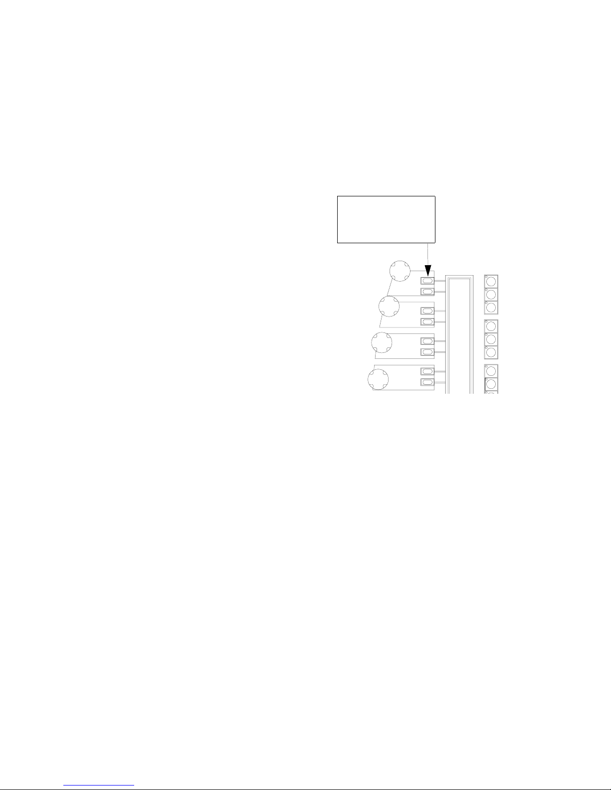
VARI❋LITE® - VIRTUOSO™ / VIRTUOSO™ DX CONSOLE USER’S MANUAL
Storing New Default Min/Max Settings
The min/max buttons associated with each function can be programmed with your
own default settings as required. These settings are referred to as hard/soft, in/out, etc.
depending on the mechanism being controlled. The initial console default settings
(which correspond to the luminaire’s actual min/max values) can be re-stored with
your own min/max settings.
The min/max settings are based on
channel selection. This means that a
different minimum and maximum setting
can be defined for every channel or for
Min/Max Button Sends default setting
to selected channels.
(User programmable.)
groups of channels as required. For
example, if Channel 1 is patched as a VL5
luminaire you could select its channel and
then store appropriate min/max settings.
You could then deselect Channel 1 and
select Channel 2 (which for example is
patched as a VL6 luminaire) and store
different min/max settings. Depending on
whether Channel 1 or Channel 2 is
selected, the min/max settings would be
different.
Frame
Dyn
Store new min/max settings:
Step 1. Press button for required set of soft encoder functions. It will be mapped to
soft encoders.
Step 2. Select luminaires to be included in min/max setting. (For example, select
some VL6 luminaires.)
Step 3. Using encoders, adjust parameter for new setting.
Step 4. Press [Store] / [Encoder Min/Max Button]. Setting is now stored for those
channels.
Add new channels to a setting:
Step 1. Select luminaires to be added to setting. (For example, select additional VL6
luminaires.)
Step 2. Press [Store] / [Encoder Min/Max Button]. Setting is now stored for new
luminaires as well as previously stored luminaires.
64 23-Sep-0 2 02.9651.0001 C
Page 91
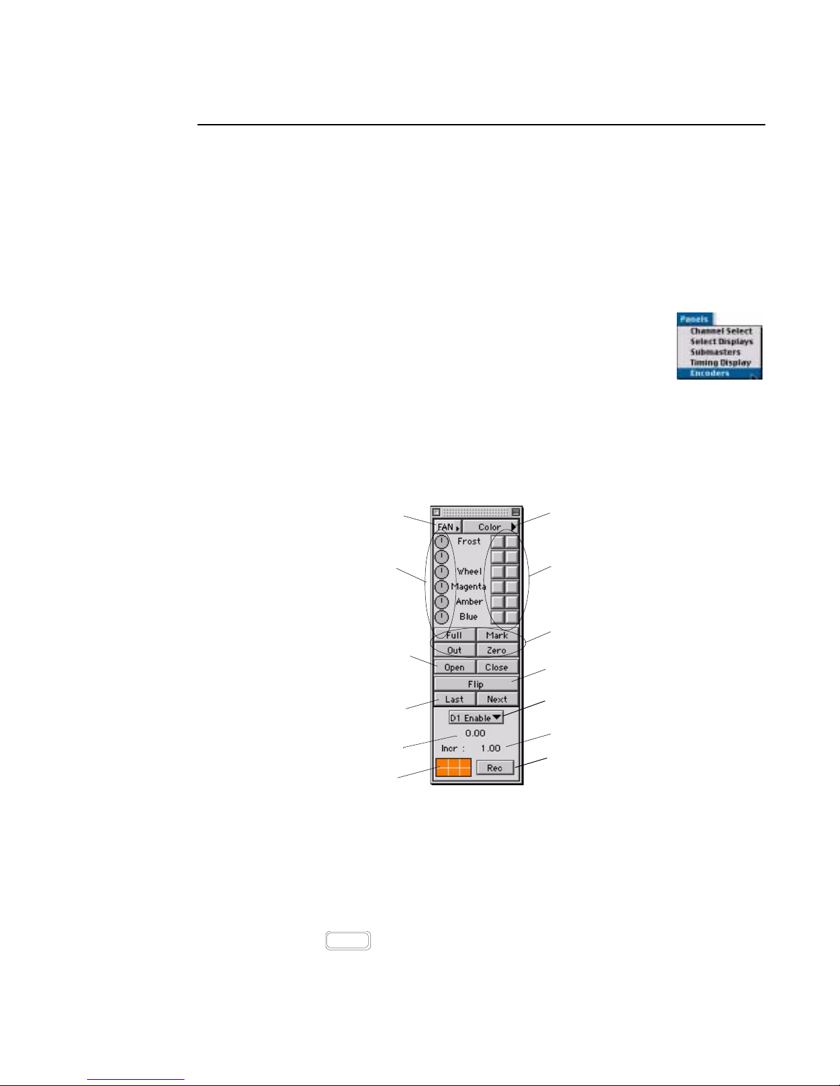
MANUAL CONTROL : ENCODER CONTROL
4
Encoders W i ndow
The Encoders window functions just as the panel encoders to provide incremental
control of luminaire parameters. In addition, it provides a visible display of currently
selected cue or effect and allows specification of a submaster for cue tracking. Refer
to the function explanations in the section “Console Encoders” on page 60 for more indepth information on each encoder function and the associated min/max settings.
To operate the window controls:
•At Panels menu, choose Encoders to open window.
• At popup menu, select encoder function: Focus, Color, Beam,
Image, Dynamic, or Frame.
• Rotate encoder by clicking and holding mouse button and then
moving left or right. Release mouse button when desired encoder setting is
reached.
• Currently selected cue/effect and increment setting are indicated at bottom portion
of window.
Fan Popup Menu
Encoder Controls
Shutter Buttons
Channel Increment
Buttons
Selected Cue/Effect
Indicator
Function Filter Grid
Function Popup Menu
Max/Min Buttons
Intensity Buttons
Pan/Tilt Flip Button
Specifies which
submaster will track
cue
Increment Indicator
Macro/Board Cue
Record Button
Store new min/max settings:
Step 1. Select luminaires to be included in min/max settings. (For example, select
some VL6 luminaires.)
Step 2. At Encoder window, select parameter group from drop-down menu.
Step 3. Using encoders in window, choose a parameter for new setting.
Step 4. Press the
button in window. Setting is now stored for those channels.
02.9651.0001 C 23-Sep-02 65
Option
button on the keyboard, and click the desired min/max
Page 92
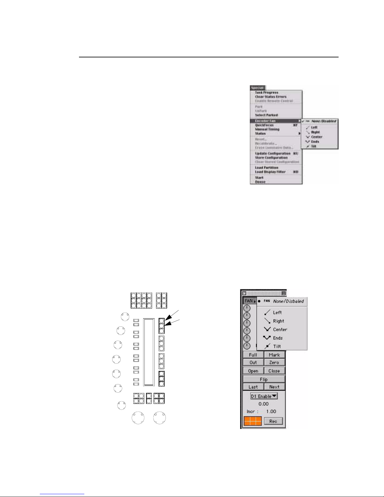
VARI❋LITE® - VIRTUOSO™ / VIRTUOSO™ DX CONSOLE USER’S MANUAL
Encoder Fan
The Encoder Fan function has been added to provide
five different types of encoder fanning. Encoder Fan
allows fanning of any encoder-controlled parameter
on a group of luminaires. The fan types available are
left fan, right fan, center fan, ends fan, and tilt fan.
Each type of fanning uses a different anchor point for
the base of the fan. Fan ordering is determined by
channel numbers and not by selection order.
Encoder fan settings can be changed from three
different locations. The Special menu, the Encoders
window, or from the Encoders panel on the console.
• Select Encoder Fan from the Special menu. Select fanning type.
• On the Encoders panel, the second Function select button displays "f". Press and
hold the "f" button, press the top Function Select button to scroll through the fan
modes. The fan mode selected here is momentary. Press and hold "f" button while
adjusting parameter encoder. Double-clicking "f" button will latch fan mode on.
The LED will flash when enabled.
• Select Encoder from the Panels menu. Click Fan for drop-down menu of encoder
fan choices.
Fan Mode
"f" button
Encoders Panel Encoders Window
66 23-Sep-0 2 02.9651.0001 C
Page 93
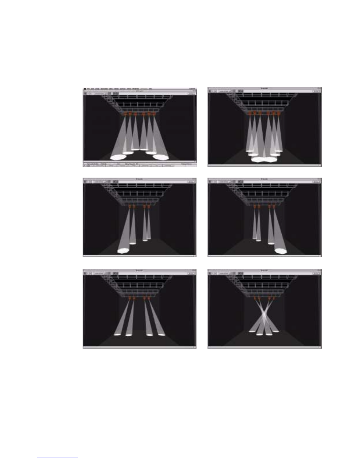
Encoder Fan Examples
Center Fan Ends Fan
MANUAL CONTROL : ENCODER CONTROL
4
Right Fan
Tilt Fan (Out) Tilt Fan (In)
Left Fan
02.9651.0001 C 23-Sep-02 67
Page 94
VARI❋LITE® - VIRTUOSO™ / VIRTUOSO™ DX CONSOLE USER’S MANUAL
Keypad Control
Overview
The control (or command-line) keypad also provides control of luminaires. Luminaire
parameters can be programmed from the keypad just as they can from the manual
control encoders, although in most cases the touch screen Sneak function is also
required. This section will cover all manual controls that can be executed using the
command-line keypad alone. Advanced manual control using the keypad will be
discussed along with the Sneak function in “Timing/Filter Displays” chapter on
page 151.
Entries made with the keypad are referred to as “command-line entries” and will be
displayed in the command-line display as they are entered.
Command-line entry guidelines:
• When entering command lines, it is not necessary to specify channel information if
the required channels are already selected. If new channels are selected for
modification on the keypad, this is reflected at the Channel Select panel.
Shortcut
• [Clear] functions as a backspace key when used during command-line
construction. [Clear] is the only thing that clears a syntax error. (Any other
keypad entry is ignored until the error condition is cleared.)
• When working from the command-line keypad, parameters will assume their new
values at full speed unless Manual Timing is currently enabled, in which case they
will use their current timing values. Only when used with the Sneak function can
the keypad selections be assigned discrete timing values.
• Since manual control requires channel selection, this can also be done using the
command-line keypad. Refer to Channel Select “From Keypad” on page 53.
FE
I
CG
select
Chan 1 ∗
B
Holding down [Clear] will clear an entire unterminated command line.
68 23-Sep-0 2 02.9651.0001 C
Page 95

MANUAL CONTROL : KEYPAD CONTROL
4
Setting Parameters From Keypad
Intensity
The keypad can be used to adjust the brightness of the luminaire’s beam. Intensity
responds to a percentage value of 0-100.
The [At] button is used to enter intensity values:
• <Chan> [n] [At] [m] [E nter] - changes the inte nsity level of the selec ted channel to
m.
• <Chan> [n] [Thru] [q] [At] [m] [Enter] - changes the intensity level for the
selected range of channels to m.
The [Full] button is used to quickly set intensity to 100%.
• <Chan> [n] [Full] [Enter] - changes the intensity level of the selected channel to
100%.
The [+] and [-] buttons can be used in combination with the [At] button to increment
or decrement a current intensity value by a specific amount. For example, if the
current intensity value is 50%:
Shortcut
• <Chan> [n] [At] [+] [0] [5] [Enter] - increases the intensity level of the selected
channel to 55%.
• <Chan> [n] [At] [-] [0] [5] [Enter] - decreases the intensity level of the selected
channel to 45%.
To quickly enter an intensity below full, but divisible by 10, use only the first digit of
the desired level (for example, [At] [5] = 50%).
Presets
The keypad can be used to assign presets to selected luminaires. The preset entered on
the keypad corresponds to the preset saved in that particular preset select (refer to
“Presets” on page 93).
Examples:
• <Chan> [n] [Preset] [m] [Enter] - applies preset m to the selected channel n (where
m is the discrete preset number).
• <Chan> [n] [Thru] [q] [Preset] [m] [Enter] - applies preset m to the selected range
of channels (where m is the discrete preset number).
Colors
The keypad can be used to assign colors to selected luminaires. The color entered on
the keypad corresponds to the color saved in that particular color select (refer to
“Colors” on page 89).
02.9651.0001 C 23-Sep-02 69
Page 96

VARI❋LITE® - VIRTUOSO™ / VIRTUOSO™ DX CONSOLE USER’S MANUAL
Examples:
• <Chan> [n] [Color] [m] [Enter] - applies color m to the selected channel n (where
m is the discrete color number).
• <Chan> [n] [Thru] [q] [Color] [m] [Enter] - applies color m to the selected range
of channels (where m is the discrete color number).
Note: Colors from the VARI❋LITE Color System can also be applied using the
keypad’s [VL Color] button. Refer to “Applying VARI❋LITE Colors” on page 105
for instructions.
Beams
The keypad can be used to assign beams to selected luminaires. The beam entered on
the keypad corresponds to the beam state saved in that particular beam select (refer to
“Beams” on page 83).
Examples:
• <Chan> [n] [Beam] [m] [Enter] - applies beam state m to the selected channel n
(where m is the discrete beam number).
• <Chan> [n] [Thru] [q] [Beam] [m] [Enter] - applies beam state m to the selected
range of channels (where m is the discrete beam number).
Note: If a profile does not provide default color and beam data, then there will be no
change for selected channels until custom color and beam selects are stored.
70 23-Sep-0 2 02.9651.0001 C
Page 97
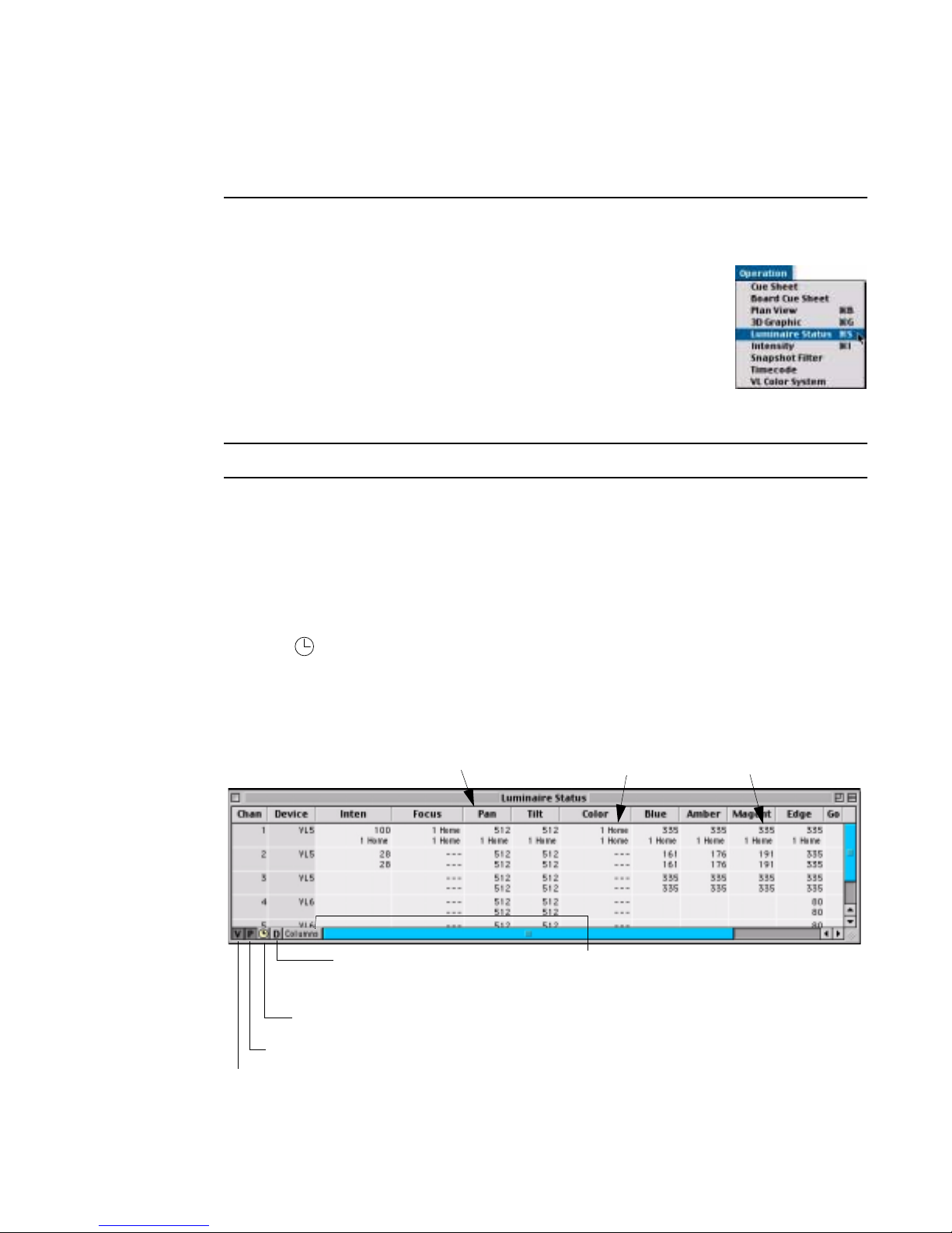
Luminaire Status
Luminaire Status Window
The Luminaire Status window can be used to view current
luminaire data as a numeric value or preset reference. (The
window is merely a way to display and review data and does not
provide editing functions.)
Open window:
•At Operation menu, select Luminaire Status. Data will be
displayed for all luminaires.
Note: Commands can be used to open multiple Luminaire Status windows.
Use the following buttons to display different types of data:
MANUAL CONTROL : LUMINAIRE STATUS
4
Value (V) button - displays the numeric value currently being received by the
luminaire for each parameter.
Parameter (P) button - displays the Preset, Color or Beam which the parameter is
currently referencing (default setting).
Timing ( ) button - displays any associated timing information.
Dynamic (D) - displays any associated dynamic state information and continuous
action such as wheel spins. Example: For Studio Color lens control, parameters
appear in Effect dynamic.
Data Columns
(configured in Parameter Columns window)
Dynamic Displays dynamic state/continuous
action information when selected
Timing - Displays timing information when selected
Parameter Data
Opens Parameter Columns window
which is used to choose which
columns appear in window
Value Data
Parameter - Displays Preset that luminaire is reporting when selected
Value - Displays value that luminaire is reporting for the parameters when selected
02.9651.0001 C 23-Sep-02 71
Page 98
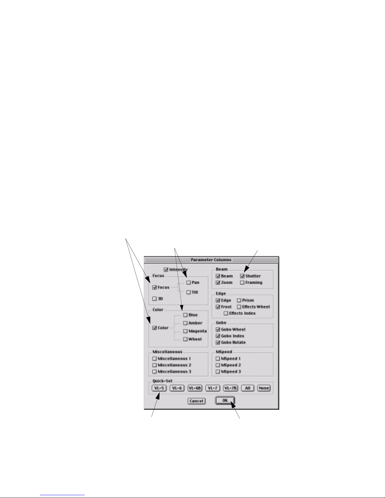
VARI❋LITE® - VIRTUOSO™ / VIRTUOSO™ DX CONSOLE USER’S MANUAL
Parameter Columns Window
The Parameter Columns window is used to define which types of information will be
displayed in the data window (columns). Using the cursor, select or deselect the boxes
as required.
For Focus and Color, two display options are available. Focus can be displayed as a
single column and/or two columns, pan and tilt. Color can likewise be displayed as a
single column and/or up to four individual color columns, which would provide data
for each filter/wheel/plate mechanism in the luminaire. When the single Focus/Color
box is checked, the column will display the Preset/Color source, as long as the data is
being taken from a single Preset/Color. If not from a single Preset/Color, then the
column would display “---”. If Pan/Tilt, etc. are checked then those columns also
display the source, or if set by encoders, the numerical values. To see both source and
# values, select [P] and [V] (at Luminaire Status window).
The Quick-Set buttons will automatically check the boxes which are applicable to a
certain type of luminaire and deselect the others, so that no excess columns will be
displayed in the window.
Displays Preset source
in single column
Displays data for components of
focus/color group columns
Checked boxes wi ll be
displayed in window
Use Quick- Set buttons to configure
window for a certain type of luminaire
72 23-Sep-0 2 02.9651.0001 C
Click OK to return to
data window
Page 99
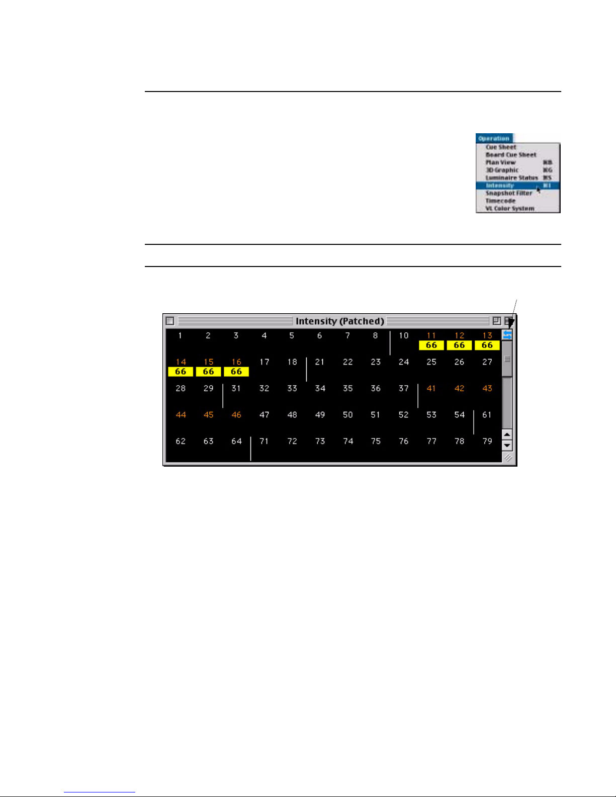
MANUAL CONTROL : LUMINAIRE STATUS
Intensity Window
The Intensity window can be used to view intensity values for all
patched channels. Selections made at the Channel Select
window or panel and/or command-line keypad are highlighted in
the window and subsequent changes to intensity values are
reflected in the display.
•At Operation menu, select Intensity. Using manual
controls, change intensity values as required. Changes will be reflected in display.
Note: Command-I opens multiple copies of the Intensity window.
Patched/All Button Toggles view between patched channels and all channels
4
Color Coding
Color coding of the intensity values provides useful information regarding how the
channels are changing from cue to cue, and if an intensity level comes from manual
control or an effect. The coloring of channel numbers and intensity values provide the
following indications:
• Selected channels are displayed in orange.
• While increasing intensity, the value changes to blue.
• While decreasing intensity, the value changes to green.
• Channels changed by manual control are displayed in black on a yellow
background.
• Channels with the same cue intensity (tracking) are displayed in pink.
• Channels changed by an effect are displayed in white on a black background.
02.9651.0001 C 23-Sep-02 73
Page 100

VARI❋LITE® - VIRTUOSO™ / VIRTUOSO™ DX CONSOLE USER’S MANUAL
For example, if channels are brought up manually using an encoder, the channel
numbers turn to gold to indicate the channel selection and the levels appear in reverse
text, which highlights the fact that they are manually controlled. Next, if a cue is
played back which overrides the intensity of these channels (HTP), the values would
revert to normal text, but would be displayed in blue - refer to “HTP (Highest Takes
Precedence)” on page 254. (If the cue does not override the intensity, they would
remain in the manual control state color.) If another cue is played back in which the
channels in blue fade down or out, they would change to green during the fade.
Configuring How Information is Displayed
In the window’s default state, all patched channels are listed horizontally with a
vertical line inserted between non-consecutive channel numbers.
User defined columns: All channels shown with unpatched channels grayed out, width
of window can be changed to modify the number of channels displayed in each row,
scroll bar allows access to all channels.
74 23-Sep-0 2 02.9651.0001 C
 Loading...