

Page 1
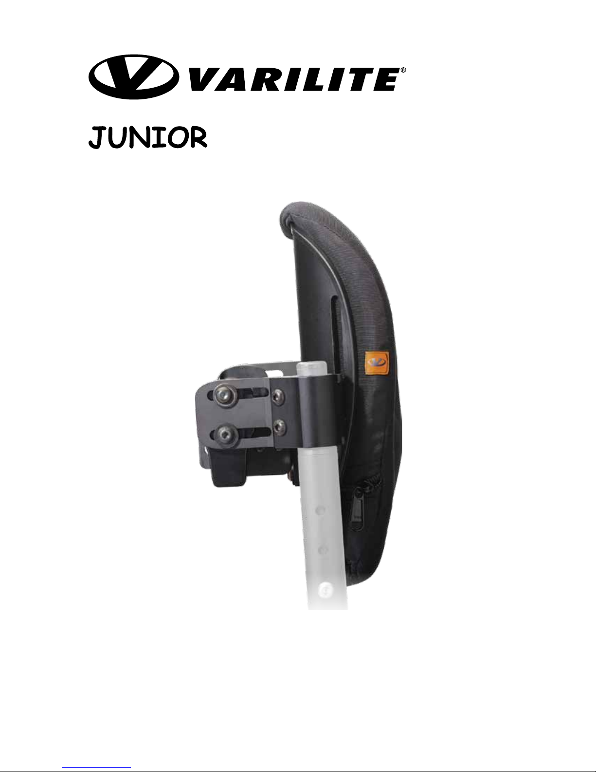
BACK SUPPORT
Installation Instructions
This manual explains how to install, operate and maintain the VARILITE JUNIOR
Back Support.
If you do not understand this instruction manual or if you have any questions,
please contact VARILITE Customer Service at (800) 827-4548.
Page 2

Page 3
Installation Instructions
Table of Contents
JUNIOR Back Support Styles Page 4
WARNINGS Pages 5-8
JUNIOR Back Support Components Pages 9-10
Assembly and Mounting Page 11
Adjustment Page 12
Seat Depth Adjustment Page 13
Operation Pages 14-15
Back Cushion Adjustment Page 16
Thoracic Support Page 16
Troubleshooting Page 17
Warranty Page 18
Care and Maintenance Page 19
Contact Information Page 19
Page 3
© 2013 Cascade Designs, Inc.
Page 4
Installation Instructions
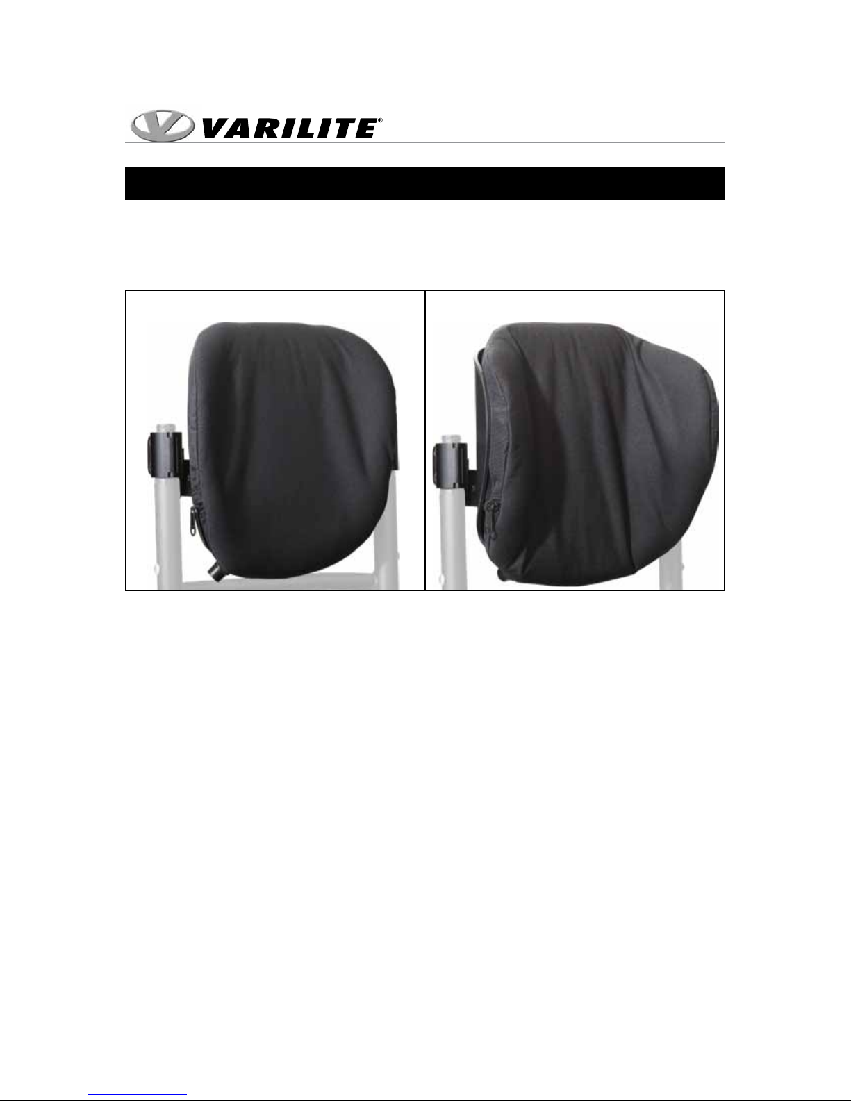
JUNIOR Back Support Styles
These instructions are applicable to the following JUNIOR Back Support Styles:
Mid
Deep
Page 4
© 2013 Cascade Designs, Inc.
Page 5
Installation Instructions
TO AVOID INJURY, read, understand and follow all instructions and
warnings in this manual before using your VARILITE back support.
There are hazards associated with the use of wheelchairs and adaptive
equipment. If you misuse your wheelchair or your back support you can be
seriously injured.
WARNING
Installation and adjustment of your VARILITE back support should be
performed only by an authorized dealer or qualified therapist.
Failure to use the appropriate equipment for restraint in a vehicle can result
in serious injury or death.
• Never use your VARILITE back support if any hardware is missing,
malfunctioning, or broken. Seek qualified assistance with any repairs or
adjustments.
• Never exceed the weight capacity of the back support. The maximum
user weight for JUNIOR back supports is 100 lbs (45 kg).
• Never exceed the weight capacity of the wheelchair as specified by the
wheelchair manufacturer.
• Never perform weight training that causes you to exceed the weight
capacity of the wheelchair.
• Do not exceed the weight capacity of the wheelchair during other
activities of daily living.
• Never lift the wheelchair by the back support.
• Never use the back support without its cover. The cover is made with
flame retardant materials. Using the back support without its cover
increases the risk of flammability.
• Never modify your VARILITE back support or use it in a way not
described by these instructions.
Page 5
© 2013 Cascade Designs, Inc.
Page 6
Installation Instructions
Wheelchair Compatibility
WARNING
VARILITE back supports are designed to be compatible with most
wheelchairs, noting the following exceptions:
The back supports can be used only with wheelchairs with round canes.
The back support can be used only with wheelchairs with cane diameters
equal to 1 in. (25 mm) or less.
Wheelchairs are not required to have stabilizer bars, provided the canes can
maintain their position.
Failure to use compatible equipment can result in equipment breakage and
serious injury.
Page 6
© 2013 Cascade Designs, Inc.
Page 7
Wheelchair Compatibility
Installation Instructions
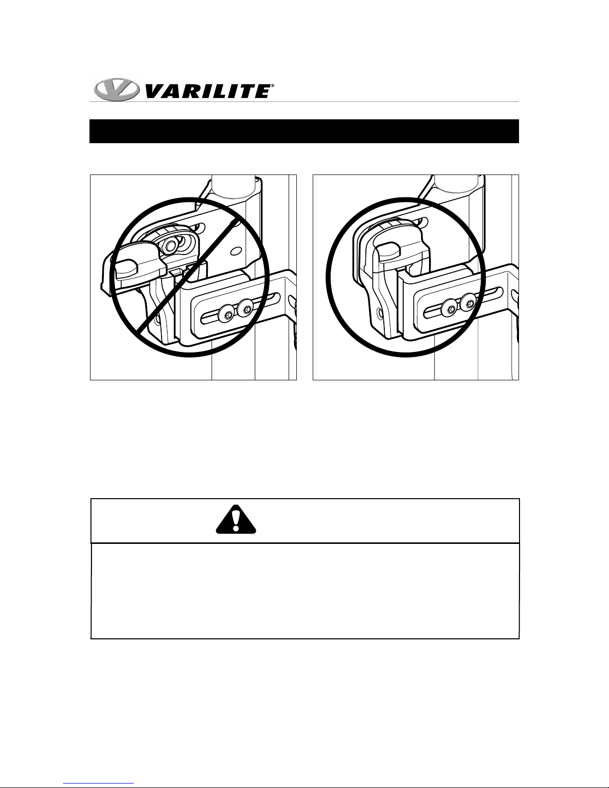
CORRECTINCORRECT
Fig. 2Fig. 1
Do not leave the Slide Caps in the open position. Doing so may allow the
Slide Brackets to disengage from the Holsters, causing the back support to
accidentally fall out, which can result in serious injury. Fig. 1 and Fig. 2.
WARNING
Page 7
© 2013 Cascade Designs, Inc.
Page 8
Installation Instructions
Wheelchair Compatibility
WARNING
Failure to install and use Cane Bracket Shims as instructed can result
in equipment breakage and serious injury.
Cane Brackets are sized for 1 in. (25 mm) diameter round wheelchair canes.
Shims are provided for wheelchair canes that are less than 1 in. (25 mm) in
diameter.
Attach Cane Bracket over shim at appropriate height. Use “Fitting Cane
Bracket Shims” chart below to properly fit your wheelchair cane diameter.
Fitting Cane Bracket Shims
Cane Size Shim Size Included with Hardware?
7/8 in. (22 mm) 1/8 in. (3 mm) Yes
3/4 in. (19 mm) 1/4 in. (6 mm) Yes
WARNING
Thoroughly clean canes before installing shims.
Grease, oil or other residue on the canes may result in shim slippage.
Shim slippage may result in equipment breakage and serious injury.
Page 8
© 2013 Cascade Designs, Inc.
Page 9
Installation Instructions
JUNIOR Back Support Components
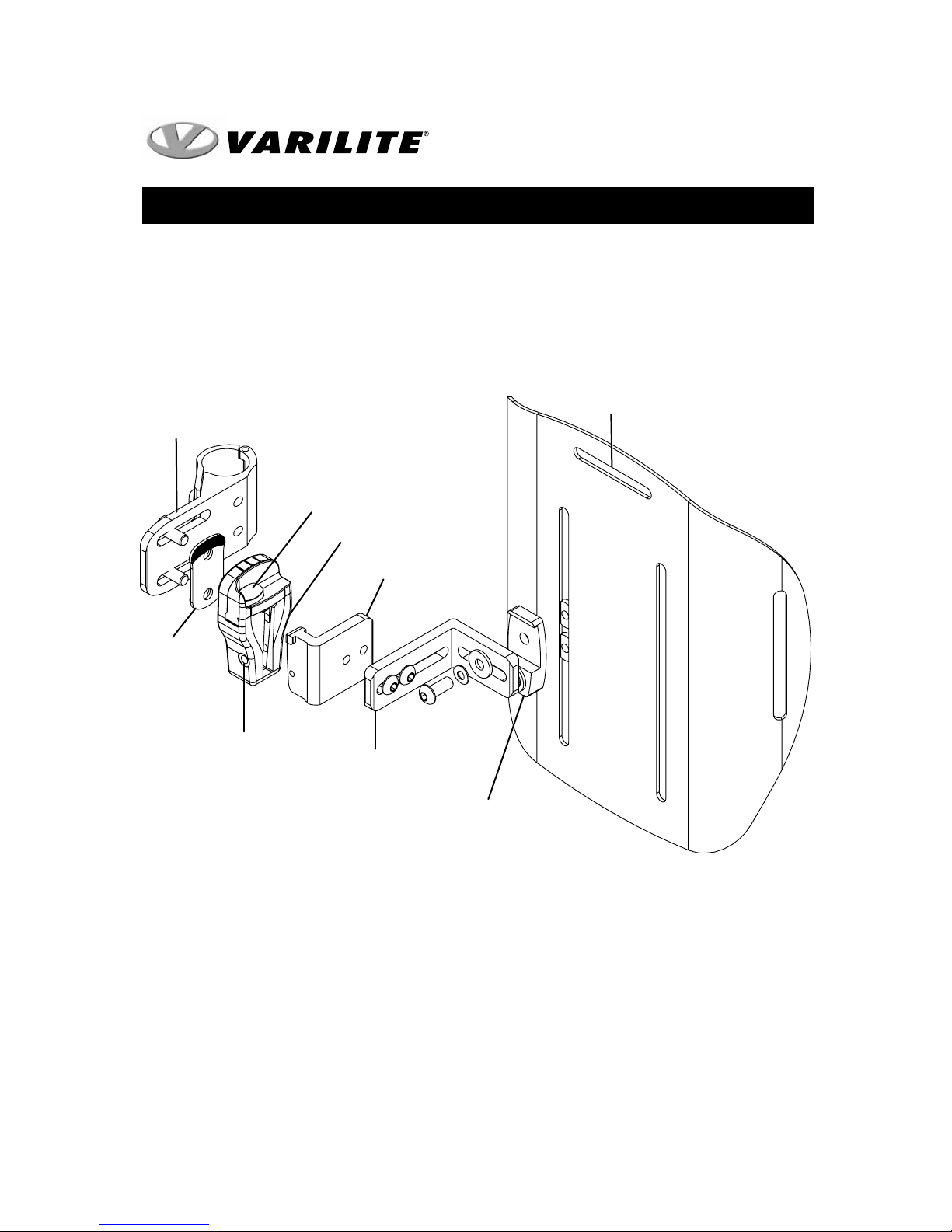
Please familiarize yourself with the parts of the back support before
installation, adjustment or use.
Cane Hardware Components
Cane
Bracket
Adjustor
Plate
Permanent
Mount
Hole
Upholstery Slot
Slide Cap
Holster
Holster
Bracket
Slide
Bracket
Shell
Bracket
Fig. 3
Page 9
© 2013 Cascade Designs, Inc.
Page 10
Installation Instructions
JUNIOR Back Support Components
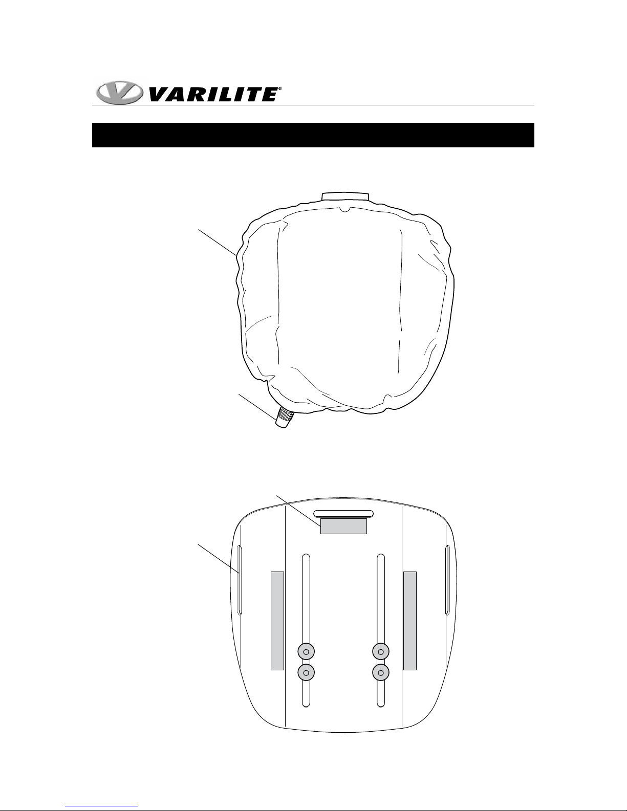
Self-Inflating Cushion
Self-Inflating
Cushion
Valve
Shell Interior
Fig. 4
Upholstery
Patch
Lateral
Slot
(Mid Shell only)
Page 10
© 2013 Cascade Designs, Inc.
Fig. 5
Page 11
Installation Instructions
Assembly and Mounting
Adjustment may be necessary to complete the installation and accommodate the
width of the wheelchair, or for desired seat depth, angle and height.
The following steps must be done before the client is in the wheelchair:
1. Determine the optimal height of the back on the wheelchair.
2. Attach Cane Brackets to each wheelchair cane, ensuring that the Holsters face
each other and the Slide Caps open rearward.
3. Align the two Cane Brackets so they are parallel and level with each other.
Tighten Cane Bracket screws enough to hold the Cane Brackets lightly in place.
4. Loosen the Slide Bracket screws.
5. Insert the back so that the Slide Brackets fit securely into the Holsters.
6. Tighten the screws on the Cane Brackets and Slide Brackets to 4.5 Newton
Meters.
7. Slide left and right Slide Caps closed, towards the shell.
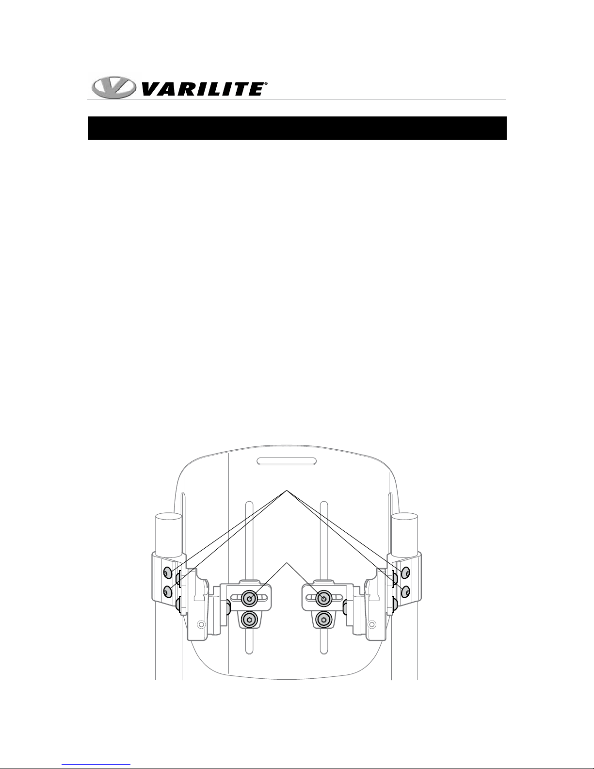
Cane Bracket
Screws
Slide Bracket
Screws
Fig. 6
Page 11
© 2013 Cascade Designs, Inc.
Page 12
Installation Instructions
Adjustment
The following steps can be done with or without someone in the wheelchair:
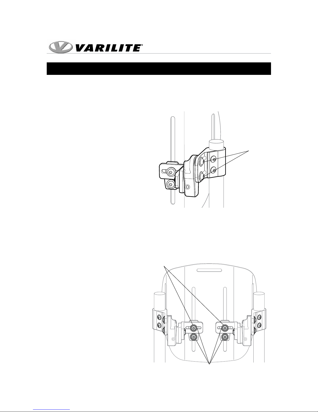
Depth and Angle Adjustments
1. Loosen the two Cane Bracket
Adjustment Screws and adjust
for desired level of depth and
angle. Only loosen adjustment
screws 3/4 of a turn to slide.
Do not disconnect from the
attached nut.
2. Use reference marks on the
top of the Holster to make
incremental adjustments.
3. Adjust the hardware on both
Cane Brackets before fully
tightening the adjustment
screws.
Cane Bracket
Adjustment
Screws
Fig. 7
4. Tighten the two Cane Bracket Adjustment Screws to maintain the adjustment.
Horizontal Shell Bracket Adjustment
1. Loosen the two Slide Bracket
Screws.
Slide Bracket
Screws
2. Make lateral shell adjustments.
3. Retighten the screws.
Vertical Shell Bracket
Adjustment
1. Loosen the two screws on each
Shell Bracket.
2. Make vertical shell adjustments.
3. Retighten the screws.
Vertical Shell
Bracket Screws
Fig. 8
Page 12
© 2013 Cascade Designs, Inc.
Page 13
Installation Instructions
Seat Depth Adjustment
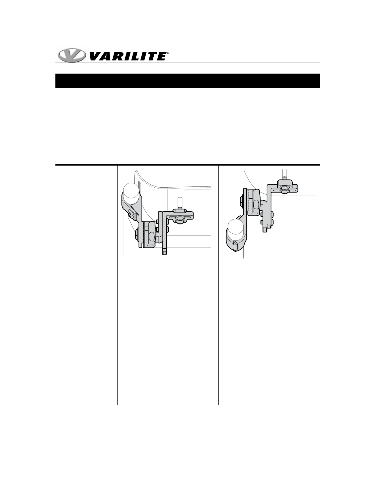
Seat depth adjustment varies according to the clinical application, specic
wheelchair features, and the recline angle of the back. The JUNIOR Back hardware
allows for seat depth adjustment in front of the canes to provide correct
positioning or allow for recline adjustment without the shell hitting the canes.
Installation Space Saver Growth
Type
Fig. 9 Fig. 10
Cane Bracket Posterior Anterior
Holster Bracket Anterior Posterior
Trunk Support From: -1.0” From: +1.9” 2
Range1 Up to: +1.25” Up to: +4.15”
Notes
1
Measured from front of canes to center of shell; cushion thickness ranges from 1 ¼" to 2 ¾" depending on inflation
2
Hardware cannot be adjusted between +1.25" and +1.9"
3
Back shell cannot be positioned behind the canes
Shell is in maximum rear
position against canes3. This
configuration frees up valuable
space behind the canes.
From Space Saver Installation:
1. Remove Holsters from Cane
Brackets
2. Flip Cane Brackets to anterior
position
3. Remount Holsters to Cane
Brackets ensuring that the
Slide Caps open rearwards
4. Remove left and right Holster
Brackets and swap them
6. Remount so tabs face upwards
Page 13
© 2013 Cascade Designs, Inc.
Page 14
Installation Instructions
Operation
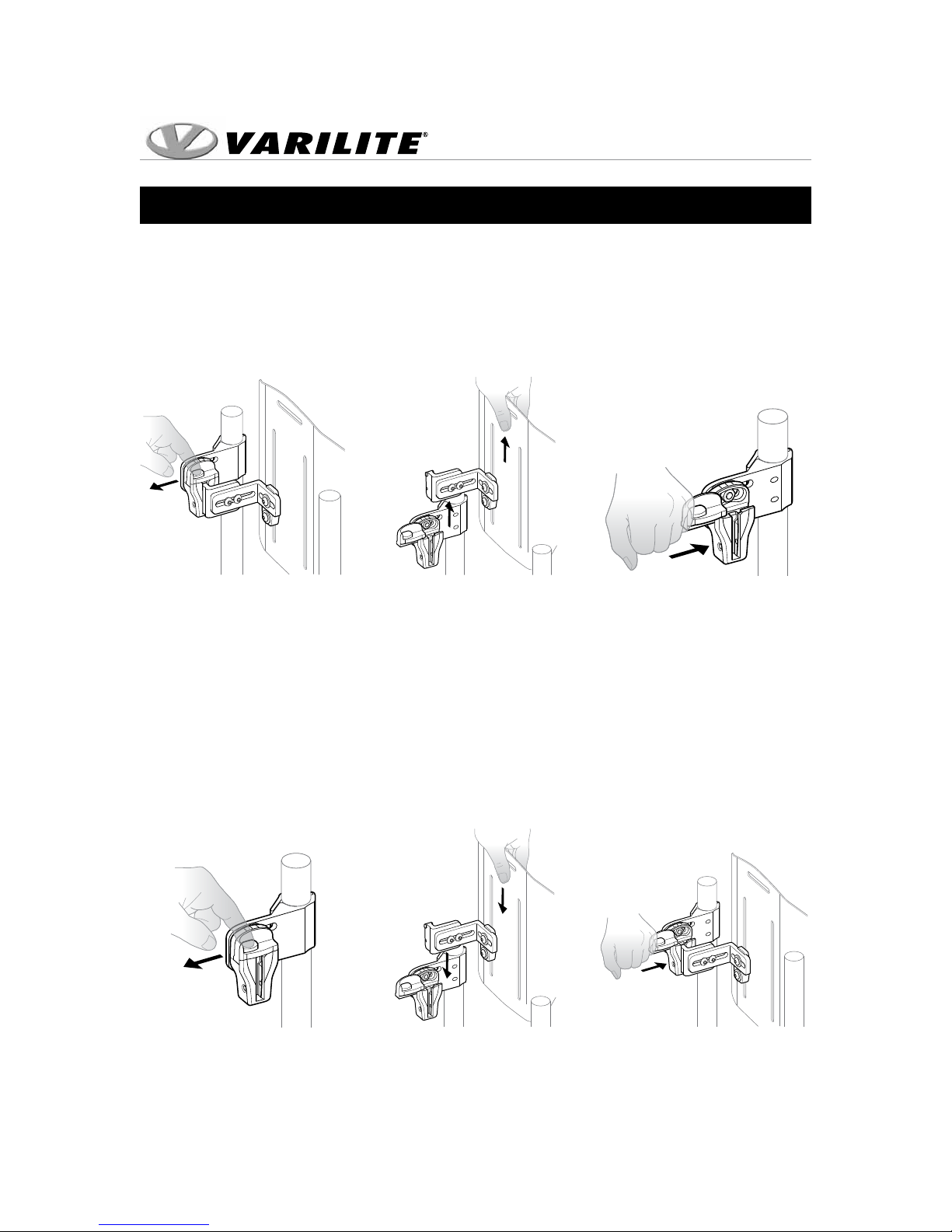
Removing the JUNIOR Back Support
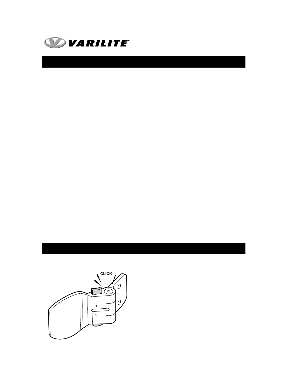
1. Depress buttons and slide the left and right Slide Caps open. Fig. 11
2. Grab the top of the shell and lift up until the Slide Bars clear the Holster. Fig. 12
3. Slide the left and right Slide Caps closed, towards the shell. Fig. 13
Fig. 11
Fig. 12
Fig. 13
Inserting the JUNIOR Back Support
1. Depress buttons and slide the left and right Slide Caps open, away from the shell. Fig. 14
2. Align the Slide Brackets above the track of the Holsters.
3. Insert the Slide Brackets into the Holsters. Fig. 15
4. Slide the left and right Slide Caps closed, towards the shell. Fig. 16
Fig. 14
Page 14
© 2013 Cascade Designs, Inc.
Fig. 15
Fig. 16
Page 15

Installation Instructions
Operation
Permanent Mount Installation
1. Loosen the left and right Slide Bracket screws. Fig. 8
2. Install the Permanent Mount Screw using the 3-32 in. hex key through the
Permanent Mount Hole into the Slide Bracket. Fig. 3
3. Tighten the left and right Slide Bracket screws.
Page 15
© 2013 Cascade Designs, Inc.
Page 16
Installation Instructions
Back Cushion Adjustment
Inflating Cushion
1. To inflate cushion, remove load from cushion.
2. Open air valve by turning valve counterclockwise.
3. When cushion is fully inflated, close air valve by turning valve clockwise.
Adjusting Cushion
1. To adjust the air level of the VARILITE back support, begin with the cushion fully
inflated and the valve closed.
2. Position wheelchair user securely in wheelchair.
3. Turn the valve counterclockwise to open the valve and release air.
4. Close the valve when the air level that provides the support needed for the
user’s comfort and functionality is reached.
Removing Cushion
1. Pull the cushion up to detach the cover from the shell.
2. Detach the Handle Flap from the Handle Patch on the inside of the Shell and pull
the Handle Flap through the slot in the Shell.
3. Remove the back cushion from the attached flap on the inside of the cover.
Note: Reverse the steps above to reattach the cushion.
Thoracic Supports Instructions
Follow installation instructions provided with the JUNIOR Thoracic Support.
Note: Although the VARILITE
JUNIOR Back Support warranty
permits drilling the Shell for
attachment of thoracic, head or
other ancillary supports, these
should be installed only by
qualified persons.
Page 16
© 2013 Cascade Designs, Inc.
Page 17

Installation Instructions
Troubleshooting
The JUNIOR Back Support should operate smoothly. The back support
should remove and insert without binding. If the back support binds or
seems “sticky” during removal and insertion, quick and easy adjustments
will correct the situation.
1. Check the back height. Ensure that the Cane Brackets are installed at the same
height and are parallel.
2. Allow the Slide Brackets to self-center. Loosen the left and right Slide Bracket
screws until the slide brackets fit loosely and self-center in the Holsters. Tighten
the Slide Bracket Screws. Fig. 8
3. Check the depth adjustment. Ensure that the depth adjustment is the same on
the left and right Holsters. Loosen the top and bottom Cane Bracket Adjustment
Screws a three-quarter (3/4) turn. While holding the back system at the
appropriate depth, tighten the top and bottom adjustment screws. Fig. 7
4. Check the angle adjustment. Ensure that the angle adjustment is the same on
the left and right Holsters. Loosen the top Cane Bracket Adjustment Screws a
three-quarter (¾) turn. While holding the back system at the appropriate angle,
tighten the top adjustment screw. Fig. 7
Note: Only loosen the Cane Bracket Screw three-quarter (¾) turn when making
angle or depth adjustments. Loosening the screw more than a three-quarter
(¾) turn will cause it to disconnect from the nut inside the Holster.
Page 17
© 2013 Cascade Designs, Inc.
Page 18

Installation Instructions
Warranty
LIMITED WARRANTY/LIMITATIONS OF REMEDIES AND LIABILITY
U.S.A. and Canada
Limited Warranty. VARILITE, a division of Cascade Designs, Inc., to the original owner (“Owner”),
under intended use and maintenance, warrants the enclosed product (“Product”) to be free from
defects in materials and workmanship for two years from date of purchase of the Product. No
warranty against defects in materials and workmanship will apply if Product is: (i) altered in any way,
except as specifically provided for in product instructions; (ii) used for purposes inconsistent with
Product’s intended purpose or design; or (iii) improperly maintained. Warranty will furthermore be
voided where user: (i) failed to follow Product instructions or warnings; or (ii) subjected Product to
misuse, abuse, or neglect.
During the warranty period, original Product parts determined by VARILITE to be defective in
materials or workmanship will be repaired or replaced as Owner’s sole remedy. VARILITE reserves
the right to replace any discontinued product with a new product of comparable value and function.
A returned product deemed irreparable becomes the property of VARILITE, and will not be returned.
EXCLUDING THE LIMITED WARRANTY PROVIDED ABOVE, VARILITE, ITS
AFFILIATES AND THEIR SUPPLIERS, TO THE MAXIMUM EXTENT PERMITTED BY LAW, MAKE
NO WARRANTIES, EXPRESSED OR IMPLIED, AND DISCLAIM ALL WARRANTIES, DUTIES AND
CONDITIONS, WHETHER EXPRESSED, IMPLIED, OR STATUTORY, WITH RESPECT TO THE PRODUCT,
INCLUDING WITHOUT LIMITATION ANY IMPLIED WARRANTIES OF MERCHANTABILITY, AGAINST
LATENT DEFECTS, FITNESS FOR A PARTICULAR PURPOSE, OR CORRESPONDENCE TO
DESCRIPTION.
Warranty Service To obtain service under this warranty, the warranty-eligible
Product must be presented to a VARILITE authorized dealer. In the United States and Canada,
warranty service may also be obtained by calling (800) 827-4548, Monday through Friday 7:00 AM to
4:30 PM Pacific Standard Time. Owner is responsible for all costs associated with returning Product
to VARILITE for service. Where at its sole discretion VARILITE deems Product eligible for warranty
repair or replacement, VARILITE will pay the shipping and handling associated with returning
repaired or replaced Product to Owner. In instances where VARILITE deems a returned product
ineligible for warranty service, VARILITE will, if possible, repair product for a reasonable charge that
includes return shipping and handling.
Limitation of Remedies Should a court of competent jurisdiction find the limited warranty set forth
above breached, VARILITE’s only obligation will be to, at its option, either repair or replace Product.
Should the aforementioned remedy fail of its essential purpose, VARILITE will, in exchange for return
of Product, refund to Owner Product’s original purchase price. THE FOREGOING REMEDY IS THE
SOLE AND EXCLUSIVE REMEDY OF THE PURCHASER AGAINST VARILITE, ITS AFFILIATES AND THEIR
SUPPLIERS, REGARDLESS OF LEGAL THEORY.
Limitation of Liability VARILITE’s, its affiliates’ and their suppliers’ maximum liability is limited
to incidental damages not to exceed the original purchase price of the Product. VARILITE, ITS
AFFILIATES AND THEIR SUPPLIERS HEREBY DISCLAIM AND EXCLUDE ANY LIABILITY FOR ANY
CONSEQUENTIAL OR OTHER DAMAGES RESULTING FROM ANY REASON WHATSOEVER. THIS
EXCLUSION AND LIMITATION APPLIES TO ALL LEGAL THEORIES UNDER WHICH DAMAGES MAY BE
SOUGHT, AND WILL APPLY EVEN IF ANY REMEDY FAILS OF ITS ESSENTIAL PURPOSE.
This limited warranty gives you specific legal rights; you may have additional rights which vary state
to state.
Always completely follow: safety, use, operation, and maintenance instructions for this or any other
VARILITE product.
European Union customer statutory rights are not affected.
Page 18
© 2013 Cascade Designs, Inc.
Page 19

Installation Instructions
Care and Maintenance
•Thealuminumshellcanbecleanedwithsoapandwarmwater.Donot
saturate. Avoid getting water under the edge trim.
•Theself-inatingcushioncanbewipedwithadampcloth.
•Thecushioncovercanberemovedandwashed.Machinewashat140°F
(60°C).Airdry.
•Neverstoreyourbacksupportinconditionsofextremeheatorexposure
to direct sunlight for long periods of time.
•Neverstoresharporheavyobjectsontopofyourbackcushion.
•Onceaweek,leavevalveopenovernight,allowingcushiontofullyinate
in an unloaded state.
Contact Information
VARILITE
4000 1st Ave. S
Seattle, WA 98134
Phone: (206) 505-9500
Toll Free: (800) 827-4548
Fax: (206) 343-5795
Toll Free Fax: (800) 363-7739
Email: [email protected]
Website: www.varilite.com
Customer Service Hours:
Monday through Friday from 7:00 AM to 4:30 PM Pacific Standard Time (PST)
Authorized EU Representative:
Cascade Designs, Limited
Dwyer Road, Midleton, Co. Cork
Republic of Ireland
A Division of Cascade Designs, Inc.
4000 1st Ave. S
Seattle, WA 98134
Phone: (800) 827-4548
Fax: (206) 343-5795
www.varilite.com
33-754
Page 19
© 2013 Cascade Designs, Inc.
Page 20

 Loading...