

Varian DS102 1Ph, DS202 1Ph, 949-9350, 949-9351, DS302 1Ph Nstruction Manual
...
DS102 1Ph
DS202 1Ph
DS302 1Ph
Dual Stage Rotary
Vane Pumps U.K.
Model 949-9350
Model 949-9351
Model 949-9352
MANUALE DI ISTRUZIONI
BEDIENUNGSHANDBUCH
NOTICE DE MODE D’EMPLOI
INSTRUCTION MANUAL
87-900-943-01(E)
JANUARY 2006

DS102 – DS202 – DS302


ISTRUZIONI PER L’USO ....................................................................................................1
GEBRAUCHSANLEITUNG .................................................................................................3
MODE D’EMPLOI................................................................................................................5
INSTRUCTIONS FOR USE.................................................................................................7
TECHNICAL INFORMATION ..............................................................................................9
SECTION I .....................................................................................................................................9
TECHNICAL DESCRIPTION.........................................................................................................9
LUBRICATION...............................................................................................................................9
VACUUM SEALS...........................................................................................................................9
GAS BALLAST VALVE................................................................................................................10
ANTI-SUCKBACK DEVICE..........................................................................................................10
TECHNICAL DATA......................................................................................................................14
DIMENSIONS....................................................................................................................15
SAFETY PRECAUTIONS............................................................................................................17
TRANSPORT AND INSTALLATION............................................................................................17
PRELIMINARY OPERATIONS....................................................................................................17
SECTION II ..................................................................................................................................18
ELECTRICAL MOTORS..............................................................................................................18
Single phase universal motors...........................................................................................18
CONNECTIONS TO THE INLET AND EXHAUST FLANGES ....................................................20
STARTING AND RUNNING THE PUMP.....................................................................................20
STOPPING THE PUMP...............................................................................................................21
SAFETY RULES..........................................................................................................................21
WARNING NOTES ,..................................................................................................21
CAUTION NOTES ....................................................................................................22
MAINTENANCE ACTIONS..........................................................................................................22
LUBRICANTS ..............................................................................................................................23
SCHEDULED MAINTENANCE CARDS......................................................................................25
UNSCHEDULED MAINTENANCE CARDS.................................................................................30
TROUBLESHOOTING AND CORRECTIVE ACTION.................................................................57
SPARE PARTS LIST ...................................................................................................................59
ISTRUZIONI PER L’USO
1 87-900-943-01(E)
INFORMAZIONI GENERALI
Questa apparecchiatura è destinata ad uso professionale. L'utilizzatore deve leggere attentamente il presente manuale di istruzioni ed ogni altra informazione addizionale fornita dalla
Varian prima dell'utilizzo dell'apparecchiatura. La Varian si ritiene sollevata da eventuali responsabilità dovute all'inosservanza
totale o parziale delle istruzioni, ad uso improprio da parte di
personale non addestrato, ad interventi non autorizzati o ad uso
contrario alle normative nazionali specifiche.
Le pompe DS102 1Ph, DS202 1Ph, DS302 1Ph sono delle
pompe rotative bistadio a palette, a tenuta in bagno d'olio, azionate da motore elettrico mono o trifase.
Queste pompe da alto vuoto sono adatte al pompaggio di gas
non corrosivi.
Nei paragrafi seguenti sono riportate tutte le informazioni necessarie a garantire la sicurezza dell'operatore durante l'utilizzo
dell'apparecchiatura. Informazioni dettagliate sono fornite nell'appendice “Technical information”.
Questo manuale utilizza le seguenti convenzioni:
,
PERICOLO!
I messaggi di pericolo attirano l'attenzione dell'operatore su una
procedura o una pratica specifica che, se non eseguita in modo
corretto, potrebbe provocare gravi lesioni personali.
ATTENZIONE!
I messaggi di attenzione sono visualizzati prima di procedure
che, se non osservate, potrebbero causare danni all'apparecchiatura.
NOTA
Le note contengono informazioni importanti estrapolate dal testo.
IMMAGAZZINAMENTO
Durante il trasporto e l'immagazzinamento delle pompe non
devono essere superate le seguenti condizioni ambientali:
− temperatura: da -20 °C a +70 °C
− umidità relativa: 0 - 95% (non condensante)
PREPARAZIONE PER L'INSTALLAZIONE
La pompa viene fornita in un imballo protettivo speciale; se si
presentano segni di danni, che potrebbero essersi verificati durante il trasporto, contattare l'ufficio vendite locale.
Il peso dell’imballo, comprensivo della pompa, è, al massimo, di
circa 27 [Kg].
Durante l'operazione di disimballaggio, prestare particolare attenzione a non lasciar cadere la pompa e a non sottoporla ad
urti o vibrazioni.
Non disperdere l'imballo nell'ambiente. Il materiale è completamente riciclabile e risponde alla direttiva CEE 85/399 per la
tutela dell'ambiente.
NOTA
La pompa non può essere danneggiata rimanendo semplicemente esposta all'atmosfera. Si consiglia comunque di mantenerla chiusa fino al momento dell'installazione sul sistema onde
evitare eventuale inquinamento da polvere.
INSTALLAZIONE
Non installare e/o utilizzare la pompa in ambienti esposti ad
agenti atmosferici (pioggia, gelo, neve), polveri, gas aggressivi,
in ambienti esplosivi o con elevato rischio di incendio.
Durante il funzionamento è necessario che siano rispettate le
seguenti condizioni ambientali:
− temperatura: da +12 °C a +40 °C
− umidità relativa: 0 - 95% (non condensante).
ATTENZIONE!
Prima di avviare la pompa, occorre procedere al rifornimento di
olio lubrificante, poichè la pompa viene fornita scarica.
,
PERICOLO!
Togliere i tappi di protezione posti sulle flange di aspirazione e
scarico prima di ogni successiva operazione. L’aria contenuta
all’interno della pompa, in caso di accensione involontaria, può
proiettarli contro l’operatore.
,
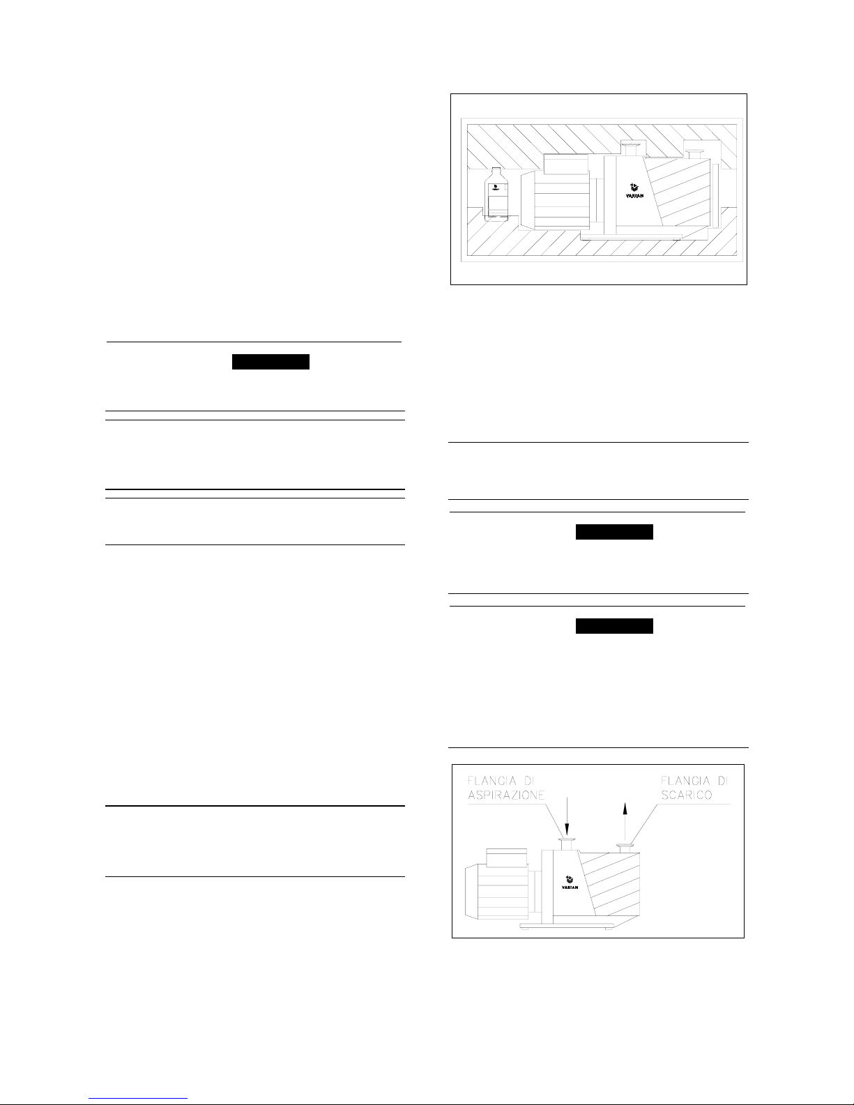
PERICOLO!
Durante l'installazione prestare la massima attenzione che la
flangia di aspirazione sia collegata alla camera da evacuare e
che la flangia di scarico non sia tappata (vedere la figura
seguente).
La pompa non deve essere usata come compressore.
La massima pressione interna al contenitore dell'olio non deve
superare 1,5 bar (abs).
L'inosservanza di queste precauzioni può causare danni alla
macchina ed all'operatore.

ISTRUZIONI PER L’USO
2 87-900-943-01(E)
ATTENZIONE!
Controllare che la tensione di alimentazione corrisponda a quella indicata sul cartellino del motore.
Collegare la pompa all’alimentazione.
ATTENZIONE!
Nel caso di motore trifase, una inversione di polarità provoca
l'inversione del verso di rotazione della pompa, con conseguenti possibili danni di natura meccanica.
USO
Prima di mettere la pompa in servizio effettivo è necessario, per
il raggiungimento del vuoto limite, far marciare per circa un’ora
la pompa con zavorra aperta allo scopo di eliminare l’umidità
nell’olio.
L'accensione della pompa non richiede particolari manovre; è
sufficiente collegarla all’alimentazione elettrica agendo
sull’interruttore bipolare (versione con motore monofase) o onnipolare (versione con motore trifase).
,
PERICOLO!
La pompa è progettata per operare con fluidi neutri o non corrosivi. È assolutamente vietato l'impiego con sostanze potenzialmente esplosive o infiammabili.
Lo spegnimento della pompa non richiede particolari manovre;
è sufficiente scollegarla dall’alimentazione elettrica agendo
sull’interruttore bipolare (versione con motore monofase) o onnipolare (versione con motore trifase).
MANUTENZIONE
Il personale addetto alla condotta ed alla manutenzione della
pompa deve essere ben addestrato e deve avere un'approfondita conoscenza delle norme antinfortunistiche.
,
PERICOLO!
Le alte tensioni possono causare morte al contatto. Operare
sempre con la massima cautela e secondo le norme antinfortunistiche in vigore.
,
PERICOLO!
Quando la macchina è alimentata prestare attenzione per la
presenza di parti in movimento e di alta tensione.
,
PERICOLO!
Nel caso si debba procedere ad operazioni di manutenzione
della pompa al termine di un periodo di esercizio, è necessario
lasciarla raffreddare, poichè la temperatura esterna può superare i 60 °C.
,
PERICOLO!
Escludere sempre l'alimentazione della pompa prima di compiere operazioni di manutenzione. Apporre specifici cartelli di
avvertenza: APPARECCHIATURA IN MANUTENZIONE - NON
INSERIRE L'ALIMENTAZIONE, in corrispondenza dell'interruttore di alimentazione. Al termine ripristinare i dispositivi di sicurezza.
,
PERICOLO!
Non effettuare la sostituzione dell’olio subito dopo l’arresto della macchina, in quanto la temperatura dello stesso può essere
elevata.
ATTENZIONE!
In fase di sostituzione di pezzi, operare con attenzione. In particolare nel caso di adozione di motore trifase, una inversione di
polarità provoca l'inversione del verso di rotazione della pompa,
con conseguenti possibili danni di natura meccanica.
NOTA
Prima di rispedire al costruttore una pompa per riparazioni è
indispensabile compilare e far pervenire al locale ufficio vendite
la scheda "Sicurezza e Salute" allegata al presente manuale di
istruzioni. Copia della stessa deve essere inserita nell'imballo
della pompa prima della spedizione.
Qualora una pompa dovesse essere rottamata, procedere alla
sua eliminazione nel rispetto delle normative nazionali specifiche.

GEBRAUCHSANLEITUNG
3 87-900-943-01(E)
ALLGEMEINE HINWEISE
Dieses Gerät ist für den professionellen Gebrauch bestimmt.
Vor dem Gebrauch soll der Benutzer dieses Handbuch sowie
alle weiteren von Varian mitgelieferten Zusatzinformationen
genau lesen. Bei vollständiger bzw. teilweiser Nichtbeachtung
der enthaltenen Hinweise, unsachgemäßem Gebrauch durch
ungeschultes Personal, nicht autorisierten Eingriffen und
Benutzung unter Mißachtung der nationalen Bestimmungen
übernimmt Firma Varian keinerlei Haftung.
Die Pumpen DS102 1Ph, DS202 1Ph, DS302 1Ph sind dichte
ölbadgeschmierte zweistufige Flügelzellenpumpen, die von
einem Ein- oder Dreiphasenstrommotor betätigt werden.
Diese Hochvakuumpumpen eignen sich für das Pumpen von
nicht korrosiven Gasen.
In den folgenden Abschnitten sind alle erforderlichen
Informationen für die Sicherheit des Bedieners bei der
Verwendung des Geräts aufgeführt. Detaillierte technische
Informationen sind im Anhang "Technical Information"
enthalten.
In dieser Gebrauchsanleitung werden Sicherheitshinweise
folgendermaßen hervorgehoben:
,
GEFAHR!
Die Gefahrenhinweise richten die Aufmerksamkeit des Bedieners auf eine spezielle Prozedur oder Praktik, die bei unkorrekter Ausführung schwere Personenschäden zur Folge haben
könnte.
ACHTUNG!
Die Warnhinweise vor bestimmten Prozeduren machen den
Bediener darauf aufmerksam, daß bei Nichteinhaltung Schäden
am Gerät entstehen können.
ANMERKUNG
Die Anmerkungen enthalten wichtige Informationen, die aus
dem Text hervorgehoben werden.
LAGERUNG
Während des Transports und der Lagerung der Pumpen sollen
die folgenden Umgebungsbedingungen gegeben sein:
− Temperatur: -20 °C bis +70 °C
− Relative Feuchtigkeit: 0 - 95% (niederschlagsfrei)
VOR DER INSTALLATION
Die Pumpe wird in einer speziellen Schutzverpackung geliefert.
Eventuelle Transportschäden sind der zuständigen örtlichen
Verkaufsstelle zu melden.
Das Verpackungsgewicht beträgt, einschließlich der Pumpe,
maximal 27 Kg.
Beim Auspacken ist darauf zu achten, daß die Pumpe nicht
fallengelassen oder Stößen oder Vibrationen ausgesetzt wird.
Das Verpackungsmaterial ist ordnungsgemäß zu entsorgen. Es
ist vollständig recyclebar und entspricht der EG-Richtlinie
85/399 für den Umweltschutz.
ANMERKUNG
Die Pumpe kann, wenn sie einfach der Atmosphäre ausgesetzt
ist, nicht beschädigt werden. Sie sollte jedoch bis zur
Installation an der Anlage geschlossen bleiben, um
Verunreinigungen durch Staub zu vermeiden.
INSTALLATION
Die Pumpe darf nicht in Umgebungen installiert und/oder
benutzt werden, die ungeschützt vor Witterungsbedingungen
(Regen, Frost, Schnee), Staub und aggressiven Gasen sind
und in denen Explosions- oder erhöhte Brandgefahr besteht.
Während des Betriebs sollen die folgenden
Umgebungsbedingungen gegeben sein:
− Temperatur: +12 °C bis +40 °C
− Relative Feuchtigkeit: 0 - 95% (niederschlagsfrei).
ACHTUNG!
Die Pumpe ist vor ihrer Inbetriebnahme mit Schmieröl zu füllen,
da sie leer geliefert wird.
,
GEFAHR!
Vor Aufnahme jeglicher Arbeiten sind die Schutzkappen an den
Saug- und Druckflanschen zu entfernen. Die im Pumpeninnern
enthaltene Luft könnte diese bei unbeabsichtigter Einschaltung
gegen den Bediener schleudern.
,
GEFAHR!
Bei der Installation ist unbedingt darauf zu achten, dass der
Saugflansch an die zu entleerende Kammer angeschlossen ist
und der Ablassflansch nicht verschlossen ist (siehe nachstehende Abbildung).
Die Pumpe darf nicht als Verdichter verwendet werden.
Der Druck im Ölbehälter darf nicht größer als 1,5 bar (abs) sein.
Bei Nichtbeachtung dieser Anweisungen besteht
Schadensgefahr für das Gerät und die Bedienperson.

GEBRAUCHSANLEITUNG
4 87-900-943-01(E)
ACHTUNG!
Kontrollieren, daß die Versorgungsspannung mit der
Spannungsangabe auf dem Typenschild des Motors
übereinstimmt.
Die Pumpe an das Versorgungsnetz anschließen.
ACHTUNG!
Bei Dreiphasenstrommotoren bewirkt eine Polumkehrung die
Umkehrung des Drehsinns der Pumpe, was Schäden an der
Mechanik zur Folge haben kann.
GEBRAUCH
Vor der eigentlichen Inbetriebnahme der Pumpe ist es zur
Erreichung des Grenzvakuums erforderlich, die Pumpe
ungefähr eine Stunde mit geöffnetem Ballast laufen zu lassen,
um die Feuchtigkeit aus dem Öl zu entfernen.
Die Einschaltung der Pumpe erfordert keine speziellen Schritte,
sie braucht nur durch Betätigung des zweipoligen (Version mit
Einphasenstrommotor) oder des allpoligen Trennschalters
(Version mit Dreiphasenstrommotor) an die elektrische
Energieversorgungsquelle angeschlossen werden.
,
GEFAHR!
Die Pumpe ist für den Betrieb mit neutralen und nicht
korrosiven Fluiden konzipiert. Der Einsatz mit potentiell
explosions- oder feuergefährlichen Substanzen ist streng
verboten.
Die Ausschaltung der Pumpe erfordert keine speziellen
Schritte, sie braucht nur durch Betätigung des zweipoligen
(Version mit Einphasenstrommotor) oder des allpoligen
Trennschalters (Version mit Dreiphasenstrommotor) von der
elektrischen Energieversorgungsquelle getrennt zu werden.
WARTUNG
Das für den Betrieb und die Wartung zuständige Personal soll
geschult sein und über eine solide Kenntnis der
Unfallschutzvorschriften verfügen.
,
GEFAHR!
Hochspannungen können bei Kontakt tödliche Folgen haben.
Es ist stets mit größter Vorsicht und gemäß der geltenden
Unfallschutzvorschriften vorzugehen.
,
GEFAHR!
Bei eingeschaltetem Gerät ist auf Bewegungs- und
Hochspannungsteile zu achten.
,
GEFAHR!
Falls die Pumpe im Anschluß an den Betrieb gewartet werden
soll, ist abzuwarten, bis sie abgekühlt ist, da ihre Oberfläche
eine Temperatur von 60°C überschreiten kann.
,
GEFAHR!
Vor Wartungsarbeiten ist die Pumpe stets energiefrei zu
schalten. Am Netzschalter sind spezielle Warnschilder
“INSTANDHALTUNG AM GERÄT – NICHT EINSCHALTEN”
anzubringen. Nach Abschluß der Arbeiten sind die
Sicherheitseinrichtungen wieder zu aktivieren.
,
GEFAHR!
Keine Ölwechsel unmittelbar nach Stillsetzung des Gerätes
vornehmen, da die Öltemperatur sehr hoch sein kann.
ACHTUNG!
Bei Ersatz von Teilen ist mit Vorsicht vorzugehen.
Insbesondere bei der Version mit Dreiphasenstrommotor
bewirkt eine Polumkehrung die Umkehrung des Drehsinns der
Pumpe, was Schäden an der Mechanik zur Folge haben kann.
ANMERKUNG
Bevor dem Hersteller eine Pumpe zur Reparatur zurückgesandt
wird, ist das Formular “Sicherheit und Gesundheit” in der
Anlage zum vorliegenden Handbuch auszufüllen und der
lokalen Verkaufsstelle zuzustellen. Eine Kopie des Formulars
ist der Pumpenverpackung vor dem Versand beizulegen.
Bei eventueller Verschrottung einer Pumpe ist diese
entsprechend der einschlägigen nationalen Vorschriften zu
entsorgen.

MODE D'EMPLOI
5 87-900-943-01(E)
INDICATIONS GÉNÉRALES
Cet appareillage a été conçu en vue d'une utilisation professionnelle. Il est conseillé à l'utilisateur de lire attentivement
cette notice d'instructions ainsi que toute autre indication fournie par Varian avant d'utiliser l'appareil. Varian décline par
conséquent toute responsabilité en cas de non-respect total ou
partiel des instructions fournies, d'utilisation incorrecte de la
part d'un personnel non formé, d'opérations non autorisées ou
d'un emploi contraire aux réglementations nationales spécifiques.
Les pompes DS102 1Ph, DS202 1Ph, DS302 1Ph sont des
pompes rotatives à deux stades à palettes, étanches en bain
d'huile, actionnées par un moteur électrique mono ou triphasé.
Ces pompes à vide poussé sont adaptées au pompage de gaz
non corrosifs.
Les paragraphes suivants fournissent toutes les indications
nécessaires pour garantir la sécurité de l'opérateur pendant
l'utilisation de l'appareillage. Des renseignements plus détaillés
se trouvent dans l'appendice “Technical information”.
Cette notice utilise les signes conventionnels suivants :
,
DANGER!
Les messages de danger attirent l'attention de l'opérateur sur
une procédure ou une manœuvre spéciale dont la mauvaise
exécution risque de provoquer de graves lésions.
ATTENTION !
Les messages d'attention apparaissent avant certaines procédures dont le non-respect peut endommager sérieusement
l'appareillage.
NOTE
Les notes contiennent des renseignements importants, extrapolés du texte.
EMMAGASINAGE
Pendant le transport et l'emmagasinage des pompes, il faut
veiller à respecter les conditions environnementales suivantes :
− température: de -20 °C à +70 °C
− humidité relative: 0 - 95% (non condensante)
PRÉPARATION POUR L'INSTALLATION
La pompe est fournie dans un emballage de protection spécial;
si l'on constate des marques de dommages pouvant s'être produits pendant le transport, contacter aussitôt le bureau de vente
local.
Le poids total de l'emballage et de la pompe est au maximum
de 27 Kg.
Pendant l'opération d'ouverture de l'emballage, veiller tout particulièrement à ne pas laisser tomber la pompe et à ne lui faire
subir aucun choc ni aucune vibration
Ne pas jeter l'emballage dans la nature. Le matériel est entièrement recyclable et il est conforme à la directive CEE 85/399
en matière de protection de l'environnement.
NOTE
La pompe ne peut être endommagée en restant simplement
exposée à l'atmosphère. Il est de toute façon conseillé de la
garder dans son emballage jusqu'au moment de sa mise en
fonction afin d'éviter toute pollution due à la poussière
INSTALLATION
Ne pas installer et/ou utiliser la pompe dans des milieux exposés aux agents atmosphériques (pluie, gel, neige), à des poussières, à des gaz agressifs ainsi que dans des milieux explosifs
ou à risque élevé d'incendie.
Pendant le fonctionnement, il est nécessaire de respecter les
conditions environnementales suivantes :
− Température: de +12 °C à +40 °C
− Humidité relative : 0 - 95% (non condensante).
ATTENTION !
Avant toute utilisation de la pompe, il est impératif de procéder
à son remplissage en huile de lubrification car elle est livrée
vide.
,
DANGER!
Avant toute autre opération, retirer les bouchons de protection
placés sur les brides d'aspiration et de vidange. En cas de mise
en marche inopinée de l'appareillage, l'air contenu à l'intérieur
de la pompe peut les projeter contre l'opérateur.
,
DANGER!
Pendant l'installation, faire très attention que la bride d'aspiration soit reliée à la chambre à vider et que la bride d'évacuation
ne soit pas bouchée (voir la figure ci-après).
La pompe ne doit pas être utilisée comme un compresseur.
La pression maximale à l'intérieur du réservoir d'huile ne doit
pas dépasser 1,5 bar (abs).
Le non-respect de ces précautions peut entraîner un danger
pour l'opérateur et l'endommagement de la machine.

MODE D'EMPLOI
6 87-900-943-01(E)
ATTENTION !
Contrôler que la tension d'alimentation correspond à la tension
indiquée sur la plaquette du moteur.
Brancher la pompe à la source d'alimentation.
ATTENTION !
En cas de moteur triphasé, une inversion de polarité provoque
l'inversion du sens de rotation de la pompe et peut entraîner
des dommages de nature mécanique
UTILISATION
Avant la mise en service de la pompe, il est nécessaire, pour
atteindre le vide maximum, de faire fonctionner la pompe pendant environ une heure avec le reniflard ouvert afin de supprimer l'humidité de l'huile.
La mise en marche de la pompe ne requiert aucune manœuvre
particulière ; il suffit de la brancher à l'alimentation électrique et
d'agir sur l'interrupteur bipolaire (version avec moteur monophasé) ou unipolaire (version avec moteur triphasé).
,
DANGER!
La pompe a été conçue pour fonctionner avec des fluides neutres ou non corrosifs. L'emploi de substances potentiellement
explosives ou inflammables est strictement interdit.
L'arrêt de la pompe ne requiert aucune manœuvre particulière ;
il suffit de la débrancher de l'alimentation électrique en agissant
sur l'interrupteur bipolaire (version avec moteur monophasé) ou
unipolaire (version avec moteur triphasé).
MAINTENANCE
Le personnel chargé de la conduite et de la maintenance de la
pompe doit avoir reçu la formation nécessaire et posséder une
connaissance approfondie des normes de prévention des accidents du travail.
,
DANGER!
Les hautes tensions peuvent entraîner la mort par contact. Veiller à toujours opérer avec le maximum de prudence et dans le
respect des normes de prévention des accidents du travail en
vigueur.
,
DANGER!
Lorsque la machine est sous alimentation, faire attention à la
présence d'organes en mouvement et de haute tension.
,
DANGER!
En cas de nécessité de procéder à des opérations de maintenance de la pompe au terme d'une période de fonctionnement,
il est indispensable de la laisser refroidir car sa température
extérieure peut être supérieure à 60°C.
,
DANGER!
Avant toute opération de maintenance, il est impératif de toujours couper l'alimentation de la pompe. Placer les pancartes
spécifiques d'avertissement : APPAREILLAGE EN COURS DE
MAINTENANCE – NE PAS BRANCHER L'ALIMENTATION,
près de l'interrupteur d'alimentation. Au terme des opérations
de maintenance, restaurer les dispositifs de sécurité.
,
DANGER!
Ne pas effectuer la substitution d'huile immédiatement après
l'arrêt de la machine car la température de cette dernière peut
être élevée.
ATTENTION !
En phase de substitution de pièces, opérer avec le maximum
d'attention. En particulier, en cas de moteur triphasé, une inversion de polarité provoque l'inversion du sens de rotation de
la pompe et peut entraîner des dommages de nature mécanique.
NOTE
Avant de retourner une pompe au constructeur pour réparation,
il est indispensable de remplir et d'adresser au bureau local de
vente la fiche "Sécurité et Santé" jointe à la présente notice
d'instructions. Une copie de celle-ci devra être mise dans l'emballage de la pompe avant expédition.
En cas de mise au rebut de la pompe, procéder à son élimination conformément aux réglementations nationales en la matière.

INSTRUCTION MANUAL
7 87-900-943-01(E)
GENERAL INFORMATION
This equipment is destined for use by professionals. The user
should read this instruction manual and any other additional
information supplied by Varian before operating the equipment.
Varian will not be held responsible for any events occurring due
to non-compliance, even partial, with these instructions, improper use by untrained persons, non-authorized interference
with the equipment or any action contrary to that provided for by
specific national standards.
The DS102 1Ph, DS202 1Ph, DS302 1Ph pumps are dualstage, rotary vane pumps oil sealed, driven by a single-phase
or three-phase electric motor.
These high vacuum pumps are suitable for pumping non corrosive gases.
The following paragraphs contain all the information necessary
to guarantee the safety of the operator when using the equipment. Detailed information is supplied in the appendix "Technical Information".
This manual uses the following standard protocol:
,
WARNING!
The warning messages are for attracting the attention of the
operator to a particular procedure or practice which, if not followed correctly, could lead to serious injury.
CAUTION
The caution messages are displayed before procedures which,
if not followed, could cause damage to the equipment.
NOTE
The notes contain important information taken from the text.
STORAGE
When transporting and storing the pumps, the following environmental requirements should not be exceeded:
− temperature: from -20° to +70 °C
− relative humidity: 0 - 95% (non-condensing)
PREPARATION FOR INSTALLATION
The pump is supplied in a special protective packing. If this
shows signs of damage which may have occurred during transport, contact your local sales office.
Total weight of the pack, including the pump, is approx. 27 Kg.
When unpacking the pump, be sure not to drop it and avoid any
kind of sudden impact or shock vibration to it.
Do not dispose of the packing materials in an unauthorized
manner. The material is 100% recyclable and complies with
EEC Directive 85/399.
NOTE
Normal exposure to the environment cannot damage the pump.
Nevertheless, it is advisable to keep it closed until it is installed
in the system, thus preventing any form of pollution by dust.
INSTALLATION
Do not install or use the pump in an environment exposed to
atmospheric agents (rain, snow, ice), dust, aggressive gases,
or in explosive environments or those with a high fire risk. During operation, the following environmental conditions must be
respected:
− temperature: from +12 °C to +40 °C
− relative humidity: 0 - 95% (non-condensing)
CAUTION
Before starting the pump, fill up with lubricating oil as the pump
is delivered empty.
,
WARNING!
Take out the protective caps on the suction and exhaust
flanges before doing anything else. In the event of an accidental start-up, the air inside the pump could violently expel the
protective caps and harm the operator.
,
WARNING!
During installation, pay maximum attention that the suction
flange is connected to the vacuum chamber and the exhaust
flange is not closed (see the following figure).
The pump must not be used as a compressor.
Maximum pressure inside the oil container must not exceed 1.5
bar (abs.)
Non-observance of these precautions may be dangerous for
the machine and the operator.

INSTRUCTION MANUAL
8 87-900-943-01(E)
CAUTION
Check that your electrical mains voltage corresponds to that
indicated on the motor’s plate.
Connect the pump to the power supply.
CAUTION
Pay special attention to the three-phase motor, where an inversion of polarity causes inversion of the direction of rotation of
the pump with consequent possibilities of mechanical damage.
USE
Before being put into service, in order to reach maximum vacuum, the pump must be left running for about an hour with the
gas ballast valve open. This will eliminate any humidity from the
oil.
There are no special procedures for switching the pump on; it
needs only to be connected to the electric power by means of
the bipolar switch (version with single-phase motor) or of the
multipolar switch (version with three-phase motor).
,
WARNING!
The pump is designed for operation with neutral or noncorrosive fluids. It is absolutely forbidden to use potentially explosive or flammable substances.
There are no special procedures for switching the pump off; it
needs only to be disconnected from the electric power by
means of the bipolar switch (version with single-phase motor)
or of the multipolar switch (version with three-phase motor).
MAINTENANCE
Personnel responsible for pump operation and maintenance
must be well-trained and must be aware of the accident prevention rules.
,
WARNING!
Death may result from contact with high voltages. Always take
extreme care and observe the accident prevention regulations
in force.
,
WARNING!
When machine is powered take care on account of moving
parts and high voltages.
,
WARNING!
If you have to perform maintenance on the pump after a considerable time in operation, leave it to cool as temperature of
the outer surface may be in excess of 60 °C.
,
WARNING!
Always disconnect the power supply to the pump before starting maintenance work. Place a special warning signs over the
power supply breaker switch: MACHINE UNDERGOING
MAINTENANCE - DO NOT POWER ON. When finished, remove the safety warning.
,
WARNING!
Do not change the oil immediately after stopping the machine
as the oil temperature may still be high.
CAUTION
When replacing a part, take great care. Pay special attention to
the three-phase motor, where an inversion of polarity causes
inversion of the direction of rotation of the pump with consequent possibilities of mechanical damage.
NOTE
Before returning the pump to the constructor for repairs the
"Health and Safety" sheet attached to this instruction manual
must be filled-in and sent to the local sales office. A copy of the
sheet must be inserted in the pump package before shipping.
If a pump is to be scrapped, it must be disposed of in accordance with the specific national standards.

TECHNICAL INFORMATION
SECTION I
TECHNICAL DESCRIPTION
The DS102 1Ph, DS202 1Ph and DS302 1Ph
pumps are dual-stage, rotary vane pumps oil
sealed, driven by a single-phase or three-phase
electric motor.
These vacuum pumps are suitable for pumping
non corrosive gases.
The main features are:
- all parts in direct contact with the fluid pumped
are free of copper alloys;
- all materials are carefully selected to provide
extended life;
- a high capacity gas ballast device allow to
pump condensable vapors;
- all the parts composing the pump are fully replaceable due to the close machining tolerances and to the centering obtained by using
reference pins;
- due to its design features and low number of
gaskets, the pump requires little maintenance,
disassembly and reassemble are easy and
require minimal time.
The pump works with force-feed lubrication, provided by an auxiliary gear-pump driven by the rotor
of the vacuum pump itself. This ensures proper
lubrication even when pressures are close to
atmospheric
.
The entire pump functional block is immersed in
the oil contained in the casing. The oil guarantees
perfect sealing of the discharge valves, enters the
pump to ensure lubrication and sealing of the parts
inside, facilitates heat dissipation and reduces
pump noise.
The pump is equipped with a special antisuckback device which automatically isolates the
vacuum system when the pump stops. This avoids
rises in pressure or oil flow in the vacuum system
while air is allowed back into the stator chambers.
The air entering the pump after the anti-suckback
device has closed prevents the oil in the casing
from filling the stator chambers.
The inner seals are achieved by the lubricating oil,
thanks to the close machining tolerances.
The vacuum pumps are connected directly to the
electric motor through a flexible coupling, so that
motion is transmitted even in case of poor alignment.
A fan fitted on the joint and housed in the pump
support produces a forced air flow over the finned
surfaces of the casing to avoid oil overheating.
LUBRICATION
The pump’s lubricating system is force-feed type.
Oil circulation is obtained by means of a gear
pump connected to the rotor shaft.
The oil is sucked through a gauze filter to prevent
any foreign bodies from entering the pump.
Shunt-mounted on the delivery line is a hydraulic
piston which, besides actuating the anti-suckback
device (see ANTI-SUCKBACK DEVICE), also
regulates pressure by discharging excess oil flow
directly into the tank.
The required flow of oil under pressure passes
through ducts that are drilled in the walls of the
pump and lubricates the bushings and the inside
parts.
VACUUM SEALS
A special feature of this pump is the low number of
gaskets that are employed.
The seals in the circuit are obtained by means of
VITON gaskets.
The careful surface finish of the various parts of
the pump means that vacuum sealing of the functional block is ensured by the film of oil separating
metal surfaces. Sealing of the rotor shaft is guaranteed by a rotating gasket with dust-guard lip.
The suction flange and duct are sealed by mean of
OR gaskets.
INLET PORT
OUTLET PORT
9 87-900-943-01(E)

TECHNICAL INFORMATION
GAS BALLAST VALVE
When the pump sucks in vapors, these condense
during compression and mix with the oil, forming
an emulsion (an aqueous vapor, for example) or a
solution (organic solvent vapors, for example).
A number of problems arise from this, such as the
impossibility of obtaining high vacuums, the alteration of the properties of the oil, could cause scaling
on parts of the pump.
To avoid this, during compression at the second
stage, atmospheric air is let into the pump through
an adjustable valve, or “gas ballast valve”, located
at the top of the pump.
In this way, the discharge valve of the second
stage opens through the effect of the atmospheric
air before the partial pressure of the vapor reaches
saturation point, thus preventing condensation
from occurring. The vapors are expelled mixed
with air.
ANTI-SUCKBACK DEVICE
The pump is equipped with a special antisuckback device to avoid air pressure rises and/or
oil backflow towards the evacuated vessel when
the pump is switched off. This device has a shutter
which automatically closes the suction duct.
In this way the pump and vacuum system are
completely isolated from each other and air can
enter the pump without any risk for the vacuum
produced in the system.
The device includes some special features,
namely:
- drive obtained avoiding any form of contamination of the inlet duct by fluids (oil and/or air)
used to command the shutter. Thanks to this,
when the pump is started again, the pumpdown to vacuum conditions is extremely fast
as these contaminants are not present and no
degassing is therefore required;
- suction flange maintained closed even when
the pump is idle, so that pollutants cannot enter from the environment and no oil can overflow from the pump.
10 87-900-943-01(E)

TECHNICAL INFORMATION
View of the pump
11 87-900-943-01(E)

TECHNICAL INFORMATION
Legend (cf. figure View of the pump)
N° Description DS 102 DS202 DS302
1 Electric motor SR03700702 SR03700702 SR03700702
1A Electric motor 370-450W SR03700865 SR03700865 SR03700865
1B Three phase electric motor SR03700922 SR03700922 SR03700922
2 Rubber foot
3 Screw
4 Screw
5 Screw
7 Spacer
8 Motor support
9 Handle
10 Screw
11 Right sideplate
12 Board
14 Screw
15 Support plate
16 Cylindrical pin (3) - (1) (3) - (2) (3) - (2)
17 Screw
18 Rubber crown (3) - (1) (3) - (2) (3) - (2)
19 Half-joint with fan
20 Half-joint (pump side)
21 Oil-seal ring (3) - (1) (3) - (2) (3) - (2)
22 Special screw
23 OR gasket (3) - (1) (3) - (2) (3) - (2)
24 Gas Ballast Valve knob SR03700219 SR03700219 SR03700219
25 Half-plate
26 Inlet screen SR03700237 SR03700237 SR03700237
27 OR gasket (3) - (1) (3) - (2) (3) - (2)
28 Suction flange
29 Anti-suckback shutter (3) - (1) (3) - (2) (3) - (2)
30 Piston
31 OR gasket (3) - (1) (3) - (2) (3) - (2)
32 Casing gasket (3) - (1) (3) - (2) (3) - (2)
33 Inner plate SR03700260 SR03700260 SR03700260
34 Pump support
35 Anti-wear bushing
36 OR gasket (3) - (1) (3) - (2) (3) - (2)
37 Kei motor side SR8999980101 SR8999980101 SR8999980101
38 First stage vane (1) (2) (2)
39 First stage rotor SR03700273 SR03700319 SR03700319
40 Spring (3) - (1) (3) - (2) (3) - (2)
41 Tongue SR8999980001 SR8999980001 SR8999980001
42 Second stage vane (1) (2) (2)
43 Second stage rotor SR03700269 SR03700269 SR03700269
44 Tie-rod SR03700209 SR03700308 SR03700308
45 OR gasket (3) - (1) (3) - (2) (3) - (2)
46 Bracket
47 Screw
49 Valve cover plate
50 Valve spring (3) - (1) (3) - (2) (3) - (2)
12 87-900-943-01(E)

TECHNICAL INFORMATION
13 87-900-943-01(E)
N° Description DS 102 DS202 DS302
51 Valve gasket (3) - (1) (3) - (2) (3) - (2)
52 First stage stator SR03700261 SR03700316 SR03700495
53 Middle plate SR03700262 SR03700262 SR03700262
56 GasBallast Valve shutter (3) - (1) (3) - (2) (3) - (2)
57 GasBallast Valve spring (3) - (1) (3) - (2) (3) - (2)
58 Second stage stator SR03700321 SR03700321 SR03700321
59 Oil pump joint SR03700280 SR03700280 SR03700280
60 Special screw
61 End plate SR03700285 SR03700285 SR03700285
62 Tongue
63 Washer
64 Nut
69A External oil pump gear SR03700281 SR03700281 SR03700281
69B Internal oil pump gear SR03700277 SR03700277 SR03700277
70 Oil pump cover
71 Screw
73 Plate
74 Filter
75 Casing
76 Exhaust flange
77 OR gasket (3) - (1) (3) - (2) (3) - (2)
78 Oil fill plug 03.701218 03.701218 03.701218
79 Oil drain plug SR03700256 SR03700256 SR03700256
80 Oil drain plug gasket SR03700256 SR03700256 SR03700256
81 Left sideplate
83 Spring
84 Filter
85 Flange
86 Sight glass 03.701326 03.701326 03.701326
87 OR gasket (3) - (1) (3) - (2) (3) - (2)
99 Special screw
100 Piston
101 Arm
102 Spring (1) (2) (2)
103 OR gasket (3) - (1) (3) - (2) (3) - (2)
104 OR gasket (3) - (1) (3) - (2) (3) - (2)
105 Sleeve
106 Spring (1) (2) (2)
107 Ring (3) - (1) (3) - (2) (3) - (2)
108 Arm
109 Insert
110 Special washer
111 Screw
NOTES
(1) Part of DS 102 Major Maintenance Kit (P/N 9499380)
(2) Part of DS 202-302 Major Maintenance Kit (P/N9499381)
(3) Part of DS 102-202-302 Minor Maintenance Kit (P/N 9499370)

TECHNICAL INFORMATION
TECHNICAL DATA
The following table lists the main technical data of the DS102 1Ph, DS202 1Ph and DS302 1Ph pumps.
TECHNICAL DATA Hz UNITS DS102 DS202 DS302
60 l/min (cfm) 114 (4) 192 (6,8) 285 (10)
FREE AIR DISPLACEMENT
50 l/min (m
3
/h) 95 (5,7) 160 (9,6) 237 (14,2)
60 cfm 3,5 5,8 8,2
PUMPING SPEED *
50 m
3
/h 5 8,3 11,6
ULTIMATE PARTIAL PRESSURE * mbar 10
-4
10
-4
10
-4
ULTIMATE TOTAL PRESSURE *
mbar
2⋅10
-3
2⋅10
-3
2⋅10
-3
ULTIMATE TOTAL PRESSURE WITH GAS BALLAST *
mbar
2⋅10
-2
2⋅10
-2
2⋅10
-2
WATER VAPOR TOLERANCE mbar 15 15 20
WATER VAPOR CAPACITY g/h 60 100 160
OIL CAPACITY min/max l 0,3/0,5 0,4/0,6 0,4/0,6
MOTOR RATING 1ph 50/60 kW 0,37/0,45 0,37/0,45 0,37/0,45
50 rpm 1500 1500 1500
NOMINAL ROTATION SPEED
60 rpm 1800 1800 1800
OIL TEMPERATURE °C 50 50 52
(pump operating) ** °F 122 122 126
OPERATING TEMPERATURE RANGE °C 12 - 40 12 - 40 12 - 40
Installation category II
Pollution degree 2
Kg 22 24 24
WEIGHT
lb 48 53 53
INLET FLANGE DN 25KF 25KF 25KF
EXHAUST FLANGE DN 25KF 25KF 25KF
Dimensions (cf. also next table):
- length, 1ph mm 454 491 491
- width mm 134 134 134
- height mm 212 212 212
* According to PNEUROP 6602
** At ultimate total pressure, 20 °C (68 °F) room temperature
14 87-900-943-01(E)
TECHNICAL INFORMATION
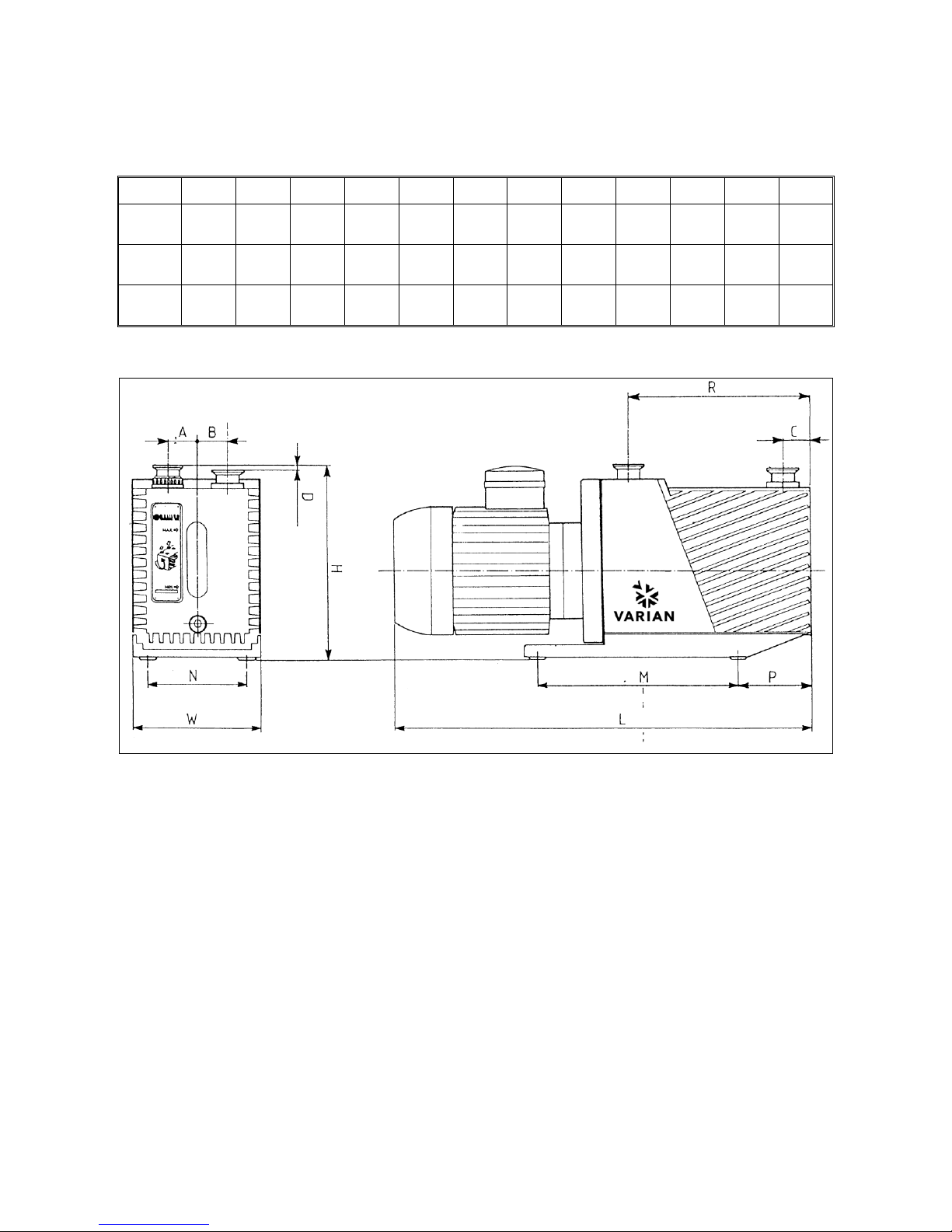
DIMENSIONS
MODEL UNITS A B C D H L M N P R W
DS102
mm
inch
30
1,18
30
1,18
35
1,38 3 0,12
212
8,3
430
16,9
250
9,8
100
3,9
105
4,1
165
6,5
132
5,2
DS202
mm
inch
30
1,18
30
1,18
35
1,38 3 0,12
212
8,3
467
18,4
250
9,8
100
3,9
105
4,1
205
8,1
132
5,2
DS302
mm
inch
30
1,18
30
1,18
35
1,38 3 0,12
212
8,3
467
18,4
250
9,8
100
3,9
105
4,1
205
8,1
132
5,2
Pump dimensions
15 87-900-943-01(E)
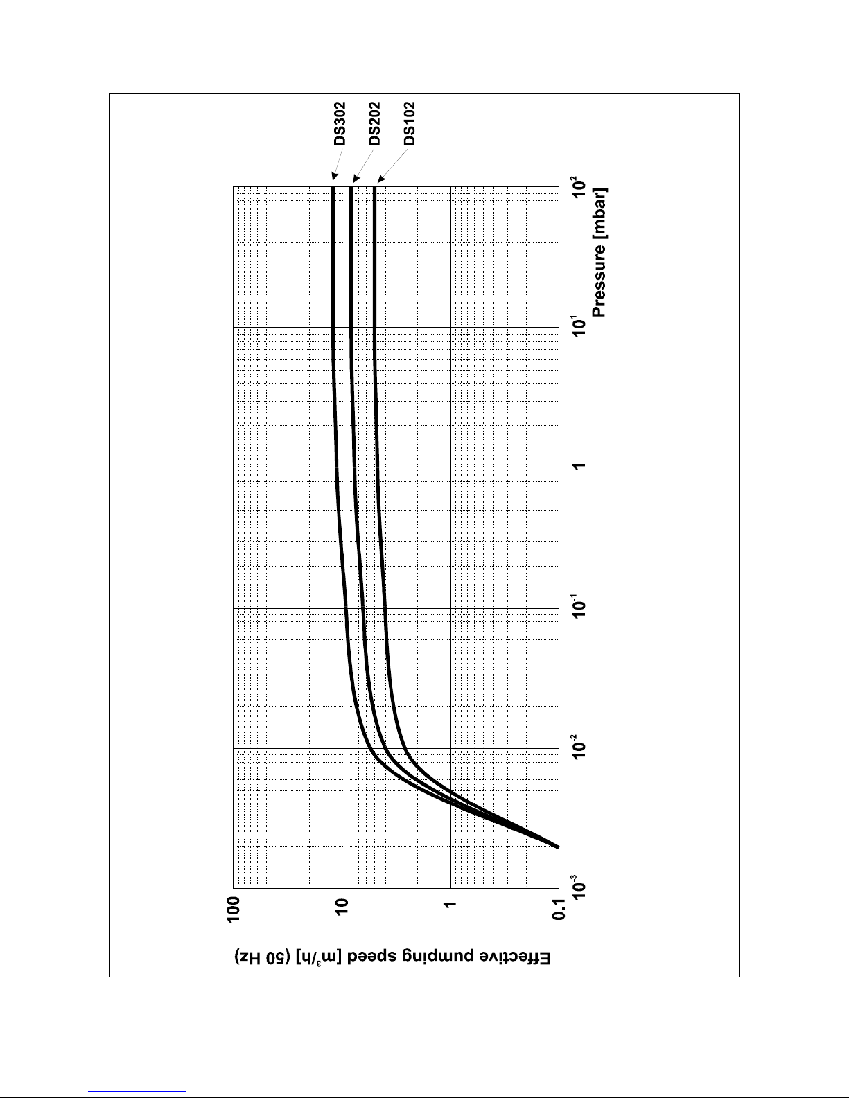
TECHNICAL INFORMATION
Typical Performance Curves
16 87-900-943-01(E)

TECHNICAL INFORMATION
SAFETY PRECAUTIONS
- Always carry the pump by means of the handles provided.
- The pump must be set in position taking the
upmost care in order to avoid accidental falls.
,
WARNING!
In case of a need to handle the pump after a period of operation, it must be left to cool first as the
external surface temperature may be in excess of
60 °C.
TRANSPORT AND INSTALLATION
The pumps are shipped to the customer inside
cardboard boxes.
Total weight of the pack, including the pump, is between 25 and 27 Kg according to the different
pump models.
The case must be handled with care, using appropriate lifting equipment.
CAUTION
When moving the case, ensure that it is securely
bound to the lifting equipment and that the equipment is strong enough to support the weight.
The pump’s working environment is a traditional
industrial environment. Naturally sites with corrosive vapors or excessive heat are best avoided.
Room temperature should ideally be between 12
°C and 40 °C.
If the temperature is not inside this range, consult
Varian technical service for the changes required.
Setting the pump in position should be performed
as follows:
- Pump laid on the ground. There are no special instructions for this type of installation, except that the floor should be as flat as
possible and suited to bear the weight of the
pump (it should ideally be a concrete floor)
and of any accessories mounted on it. Note
that the pump is stable on its base plate and it
should not be necessary to anchor it to the
floor with bolts and screws; also vibrations to
and from the pump are greatly reduced by the
use of rubber feet.
- Pump off the ground. In this case, the user
must design a suitable support structure, remembering the following points:
* the plane supporting the pump must be
perfectly horizontal;
* the structure should be adequately rigid;
* the relevant safety precautions should be
applied.
Note also that the pump should be attached to
the supporting structure after replacing the
rubber feet with special anti-vibration feet,
which should be screwed to the pump base
and to the supporting plane.
After taking the pump out of its packing case, you
are advised to make the following checks:
a. Ensure that the pump has not suffered any
damage during shipping.
b. Check that the guards are mounted correctly
(side plates, refs. 11 and 81 in fig. View of the
pump) and that there are no uncovered or
loose parts.
PRELIMINARY OPERATIONS
Before starting the pump, fill up with lubricating oil
as the pumps are delivered empty.
NOTE
A tin of oil is included in the packing.
For details on how to fill up, see Scheduled Maintenance Card 01.
CAUTION
Oil must be poured into the casing through the
special threaded plughole and NOT through the
suction line.
,
WARNING!
Take out the protective caps on the suction and
exhaust flanges before doing anything else. In the
event of an accidental start-up, the air inside the
pump could violently expel the protective caps and
harm the operator.
17 87-900-943-01(E)

TECHNICAL INFORMATION
The motor has a main on/off bipolar switch.
SECTION II
ELECTRICAL MOTORS
The motor includes a thermal protection against
overloads. If the motor is switched off by this relay,
it can be started again after a few minutes.
Single phase universal motors
They are world wide motors, dual voltages and
dual frequencies, and they are in accordance with
major international standards (UL, CSA, CE). On
the table below are shown the technical specifications of the motor.
Consult the trouble shooting section in order to
understand and remove the overload cause.
NOTE
If fuses are installed on the power line, they must
be in accordance with the table below.
CAUTION
If you start a pump at low temperature, the current
absorbed by the motors will be for several seconds
higher than the nominal one, for this reason the
fuse on the line must be of the slow-blow type.
Before connecting to the mains, check the position
of the voltage selector situated inside the electrical
box (see next paragraph).
200 to 240 V,
50/60 Hz
100 to 120 V,
50/60 Hz
Voltage selector
Motor specifications for different pumps
PUMP NOMINAL
VOLTAGE [V]
Hz RPM kW START UP
CURRENT [A]
FULL LOAD
CURRENT [A]
MAXIMUM FUSE
RATING [A]
100 50 1450 0.37 31 6.3 8
100 to 120 60 1730 0.45 33 6.5 8
200 to 240 50 1450 0.37 19 3.5 6
DS 102
DS 202
DS 302
200 to 230 60 1730 0.45 17 3.7 6
18 87-900-943-01(E)
TECHNICAL INFORMATION
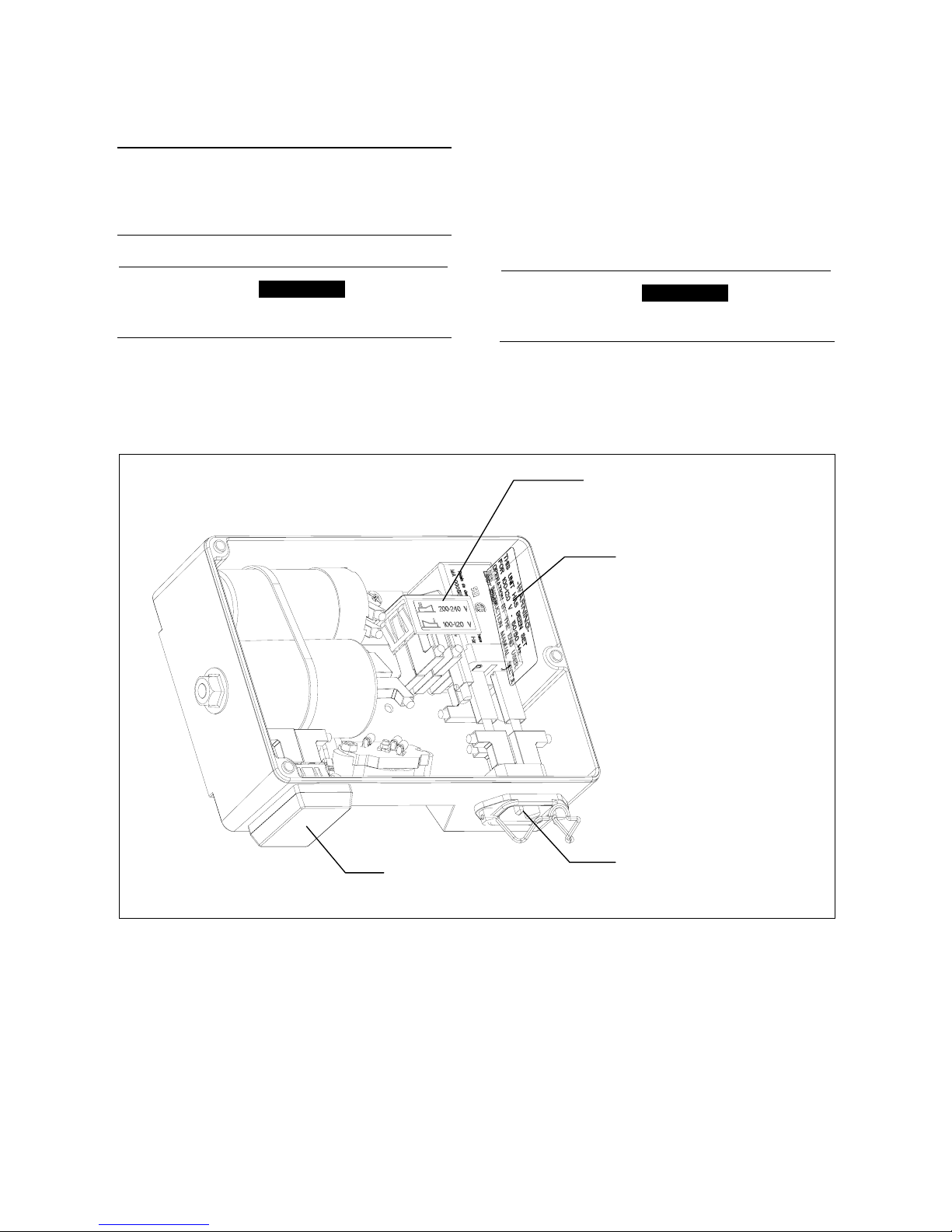
Single-Phase Universal Motors Voltage Setting
CAUTION
Before connecting to the mains, check that your
electrical mains voltage corresponds to the motor
voltage setting.
,
WARNING!
Disconnect the motor from the mains before opening the electrical box.
The motors are factory set to operate at 200-240 V
(50/60 Hz) nominal voltages.
To modify the voltage setting, change the position
of the voltage selector situated inside the motor
electrical box.
To confirm the change of the voltage setting from
High Voltage to Low Voltage, glow the orange label above the yellow label positioned on the electrical box cover.
,
WARNING!
Close the motor electrical box cover before connecting to the main.
Voltage Selector
Orange label (100 to 120 V)
IEC 320 main socket
On/off switch
Motor Electrical box
19 87-900-943-01(E)
 Loading...