

Page 1

Varian BV
Herculesweg 8
4330 EA Middelburg
The Netherlands
CP-4900 Micro-GC
User Manual
North/South America
2700 Mitchell Drive
Walnut Creek
94598 California, USA
Tel: ++(1)9259392400
Fax: ++(1)9259452360 or
++(1)9259452344
© 2002-2009 Varian, Inc. All Rights Reserved Printed in the Netherlands CP501265 Rev:7 August 2009
Europe
P.O. Box 8033
4330 EA Middelburg
The Netherlands
Tel: ++(31)118671000
Fax: ++(31)118623193
Australia/East Asia
679 Springvale Road
Mulgrave, Victoria 3171
Australia
Tel: ++(61)395607133
Fax: ++(61)395607950
Page 2

Varian Analytical Instrument Warranty
HARDWARE PRODUCTS
All analytical instruments sold by Varian are warranted to be free from defects in material and workmanship for the
periods specified and in accordance with the terms on the face of Varian's quotation or as otherwise agreed upon in
writing between Varian and the Customer. The warranty period begins on the date of shipment from Varian to the
original Customer. However, where installation is paid for by the Customer or included in the purchase price, the
warranty period begins upon completion of installation. If the Customer schedules installation to start later than 30 days
after delivery or if such delay is caused through the Customer's inability to provide adequate facilities or utilities or
through failure to comply with Varian's reasonable pre-installation instructions or through other omissions by Customer,
then the warranty period starts on the 31st day from date of shipment. Moreover Varian will charge the Customer for
labor and other expenses involved in making multiple or follow-up installation service calls.
SOFTWARE PRODUCTS Where software is provided within the frame of a license agreement concluded between the Customer and Varian, any
warranty shall be strictly in accordance with the terms of such agreement.
In the absence of a license agreement and unless an alternate warranty period is agreed upon in writing between Varian
and the Customer, the warranty period is as specified on the face of Varian's quotation. Varian warrants such software
products, if used with and properly installed on Varian hardware or other hardware as specified by Varian to perform as
described in the accompanying Operator's Manual and to be substantially free of those defects which cause failure to
execute respective programming instructions; however, Varian does not warrant uninterrupted or error-free operation.
REMEDIES
The sole and exclusive remedy under hardware warranty shall be repair of instrument malfunctions which in Varian's
opinion are due or traceable to defects in original materials or workmanship or, at Varian's option, replacement of the
respective defective parts, provided that Varian may as an alternative elect to refund an equitable portion of the
purchase price of the instrument or accessory.
Repair or replacement under warranty does not extend the original warranty period.
Repair or replacement under warranty claims shall be made in Varian's sole discretion either by sending a Customer
Support Representative to the site or by authorizing the Customer to return the defective accessory or instrument to
Varian or to send it to a designated service facility. The Customer shall be responsible for loss or damage in transit and
shall prepay shipping cost. Varian will return the accessory or instrument to the Customer prepaid and insured. Claims
for loss or damage in transit shall be filed by the Customer. To correct software operation anomalies, Varian will issue
software revisions where such revisions exist and where, in Varian's opinion, this is the most efficient remedy.
LIMITATION OF WARRANTY
This warranty does not cover software supplied by the Customer, equipment and software warranted by another
manufacturer or replacement of expendable items and those of limited life, such as but not limited to: Filters, glassware,
instrument status lamps, source lamps, septa, columns, fuses, chart paper and ink, nebulizers, flow cells, pistons, seals,
fittings, valves, burners, sample tubes, probe inserts, print heads, glass lined tubing, pipe and tube fittings, variable
temperature dewars, transfer lines, flexible discs, magnetic tape cassettes, electron multipliers, filaments, vacuum
gaskets, seats and all parts exposed to samples and mobile phases.
This warranty shall be void in the event of accident, abuse, alteration, misuse, neglect, breakage, improper operation
or maintenance, unauthorized or improper modifications or tampering, use in an unsuitable physical environment, use
with a marginal power supply or use with other inadequate facilities or utilities. Reasonable care must be used to avoid
hazards.
This warranty is expressly in lieu of and excludes all other express or implied warranties, including but not
limited to warranties of merchantability and of fitness for particular purpose, use or application, and all other
obligations or liabilities on the part of Varian, unless such other warranties, obligations or liabilities are
expressly agreed to in writing by Varian.
LIMITATION OF REMEDIES AND LIABILITY
The remedies provided herein are the sole and exclusive remedies of the Customer. In no case will Varian be
liable for incidental or consequential damages, loss of use, loss of production or any other loss incurred.
.
Page 3

Declaration of Conformity
We hereby Declare that the equipment listed below complies with the requirements of:
The Low Voltage Directive 73/23/EEC (93/68/EEC)
LVD
The EMC Directive 89/336/EEC (92/31/EEC and 93/68/EEC)
APPLICABLE STANDARDS
EN 61010-1 CSA 22.2 No. 1010.1-92 UL 3101-1
EMC
Type of Equipment:
EN 61326-A1 47CFR part 15 ANSI C63.4-1992
Micro Gas Chromatograph
Print Name: G. A. Wassink
Signed:
Position: Quality Manager
Date: November 28, 2001
AUTHORIZED REPRESENTATIVE – USA
Print Name: Martin O’Donoghue
Signed:
Position: General Manager
Date: November 28, 2001
Model:
MANUFACTURER - EU
Company Name:
Address:
Telephone:
Company Name:
Address:
Telephone:
Varian B.V.
Herculesweg 8
P.O. Box 8033
4330 EA Middelburg
The Netherlands
+31(0) 118 671 000
Varian, Inc.
2700 Mitchell Drive
Walnut Creek, California 94598
USA
925-939-2400
CP-4900
Page 4
.
Page 5

Page 6

Page 7

Safety Information
Safety Information
INFORMATION
In accordance with Varian’s commitment to customer service and safety, this instrument and its
accompanying documentation (NEN 5509) complies with the CE specifications and the safety
requirements for electrical equipment for measurement, control, and laboratory use
CSA
(CEI/IEC 1010-1),
This device has been tested and found to comply with the limits for a Class A digital device,
pursuant to part 15 of the FCC rules. These limits are designed to provide reasonable pro tection
against harmful interference when the equipment is operated in a commercia l environment. This
equipment generates, uses, and can radiate radio frequency energy and, if not installed and used
in accordance with the instruction manual, may cause harmful interference to radio
communications.
Operation of this equipment in a residential area is likely to case harmful inter ference in witch c ase
the user will be required to correct the interfer ence at his own e xpense.
To prevent any injury to the user or any damage to the instrument it is essential that you read the
information in this chapter.
If this manual is not in your native language and if you have problems understanding the text, we
advise you to contact your Varian office for assistance. Varian cannot accept responsibility for any
damage or injury caused by misunderstanding of the information in this manual.
c
and FCC-b.
us
OPERATING INSTRUCTIONS
This instruction manual is provided to help you establish operating conditions, which will perm i t
safe and efficient use of your equipment.
Special considerations and precautions are also described in the manual, which appear in the
form of NOTES, CAUTIONS, and WARNINGS as described belo w (next pag e).
It is important that you operate your equipment in accordance with this instruction manual and
any additional information, which may be provided by Varian. Address any questions regarding
the safe and proper use of your equipment to your local Varian office.
Varian, Inc. User Manual CP-4900 Micro-GC Page:I
Page 8

Safety information
CAUTION
WARNING
Information to aid you in
obtaining optimal performance
from your instrument.
Alerts you to situations that
may cause moderate injury
and/or equipment damage,
and how to avoid these
situations.
Warning Symbol Warning Description
WARNING:
Shock hazard
WARNING:
Burn hazard
Instruction
Manual
Protective
Conductor terminal
Radioactive
hazard
Skin puncture
Static discharge
Warning
Do not touch
Indicates dangerous voltage: (terminals fed from the interior
by voltage exceeding 1000V must be so marked).
Indicates parts that may cause burns when touched.
Indicates that the user should refer to the manual before
operating the equipment.
For protection against electrical shock in case of a fault. Used
with field wiring terminals to indicate the terminal, which must
be connected to ground before operating equipment.
Indicates that the inst rum ent co ntai ns ra dioac tive
components, which may cause personal injury when handled
incorrectly.
Indicates sharp or suddenly moving parts such as injection
needles that may cause injury.
Indicates instrument contains parts that can be damaged by
electrostatic discharge. Take care for proper grounding
before handling.
Touching this item may result in damage to the instrument
or personal injury.
Alerts you to potentially
hazardous situations that
could result in serious injury,
and how to avoid these
situations.
Page II User Manual CP-4900 Micro-GC Varian, Inc.
Page 9

Safety Information
GENERAL SAFETY PRECAUTIONS
Follow these safety practices to ensure safe equipment operation.
• Perform periodic leak checks on all supply lines and pneumatic
plumbing.
• Do not allow gas lines to become kinked or punctured. Place lines
away from foot traffic and extreme heat or cold.
• Store organic solvents in fireproof, vented and clearly labeled
cabinets so they are easily identified as toxic and/or flammable
materials.
• Do not accumulate waste solvents. Dispose of such materials
through a regulated disposal program and not through municipal
sewage lines.
NOTICE:
This instrument has been tested per applicable requirements of EMC
Directive as required to carry the European Union CE Mark. As such, this
equipment may be susceptible to radiation/interference levels or
frequencies, which are not within the tested limits.
This instrument is designed for chromatographic anal ysis of appropriately
prepared samples. It must be operated using appropriate gases and/or
solvents and within specified maximum ranges for pressure, flows, and
temperatures as described in this manual. If the equipment is used in a
manner not specified by the manufacturer, the protection provided by the
equipment may be impaired.
It is the responsibility of the Customer to inform Varian Customer Support
Representatives if the instrument has been used for the analysis of
hazardous biological, radioactive, or toxic samples, prior to any
instrument service being performed or when an instrument is being
returned to the Service Center for repair.
CAUTIONS
1. Disconnect the instrument from all power sources before removing protective panels to
avoid exposure to potentially dangerous voltages.
2. When it is necessary to use a non-original power cord plug, make sure the replacement
cord adheres to the color-coding and polarity described in the manual and all local
building safety codes.
3. Replace faulty or frayed power cords immediately with the same type and rating.
4. This instrument should be placed in a suitable location with sufficient ventilation to
remove gases and vapors. Space around the instrument must be sufficient to
enable cooling of the instrument.
Varian, Inc. User Manual CP-4900 Micro-GC Page:III
Page 10

Safety information
5. Before plugging the instrument in or turning the power on, always make sure that
the voltage and fuses are set appropriately for your local power source.
6. Do not turn on the instrument if there is a possibility of any kind of electrical damage.
Instead, disconnect the power cord and contact your Varian office.
7. The supplied power cord must be inserted into a power outlet with a protective earth
ground connection. When using an extension cord, make sure that the cord is also
properly grounded.
8. Do not change the external or internal grounding connections as this could
endanger you and/or damage the instrument.
9. The instrument is properly grounded when shipped. You do not need to make any
changes to the electrical connections or to the instrument chassis to ensure safe
operation.
10. When working with this instrument, follow the regulations for GLP (Good Laboratory
Practice). Take care to wear safety glasses and appropriate clothing.
11. Do not place containers with flammable liquids on this instrument. Spillage of the
liquid over hot parts may cause fire.
12. This instrument may use flammable or explosive gases e.g. hydrogen under
pressure. Be sure to be familiar with and to follow accurately the operation
procedures prescribed for those gases before operating the instrument.
13. Never try to repair or replace any component that is not described in this manual
without the assistance of a Varian service engineer. Unauthorized repairs or
modifications will result in rejection of warranty claims.
14. Always disconnect the AC power cord before attempting any type of maintenance.
15. Use proper tools when working on the instrument to prevent danger for you and/or
damage to the instrument.
16. The customer should not attempt to replace battery(s) or fuse(s) in this instrument
other then specified in the manual.
17. Damage can result if the instrument is stored under unfavorable conditions for
prolonged periods (e.g., subject to heat, water, etc.).
18. Do not shut off column flow when the oven temperature is high this may damage
the column.
19. This unit has been designed and tested in accordance with recognized safety
standards and designed for use indoors.
20. If the instrum ent is used in a manner not specified by the manufacturer, the
protection provided by the instrument may be impaired.
21. Substituting parts or performing any unauthorized modification to the instrument
may result in a safety hazard.
22. Changes or modifications not expressl y approved by the responsible party for
compliance could void the user’s authority to operate the equipment.
Page IV User Manual CP-4900 Micro-GC Varian, Inc.
Page 11

Safety Information
SPARE PARTS AVAILABILITY
It is the policy of Varian to provide operational spare parts for any instrument and
major accessory for a period of five (5) years after shipment of the final production
run of that instrument. Spare parts will be available after this five (5) year period
but on an as available basis. Operational spare parts are defined as those
individual electrical or mechanical parts that are susceptible to failure during their
normal operation. Examples include relays, lamps, temperature probes, detector
elements, motors, etc. Sheet metal parts, structural members or assemblies and
castings, printed circuit boards, and functional modules are normally capable of
being rebuilt to like-new condition throughout their useful life and therefore will be
supplied only on an as available basis after the final production run of the
instrument.
SERVICE AVAILABILITY
Varian provides a variety of
services to support its customers
after warranty expiration. Repair
service can be provided by
attractively priced service
contracts or on a time and
material basis. Technical
support and training can be
provided by qualified personnel
on both a contractual or asneeded basis.
Varian Analytical Instruments Sales Offices
For Sales or Service assistance and to order Parts and Supplies, contact your local Varian
office.
Argentina
Buenos Aires
Tel. +54.11.4.783.5306
Australia
Mulgrave, Victoria
Tel. +61.
Austria
Poettelsdorf
Tel. +43.2626.20090
Benelux
Middelburg
Tel. +31.118.671500
Brazil and Latin America (S)
São Paulo
Tel. +55.11.3845.0444
Canada
Mississauga, Ontario
Tel. 800.387.2216
China
Beijing
Tel. +86.106310.8550
Europe
Middelburg, The Netherlands
Tel. +31.118.671.000
3.9560.7133
France
Les Ulis Cédex
Tel. +33.1.6986.3838
Germany
Darmstadt
Tel. +49.6151.7030
India
Mumbai
Tel.
+91.22.2570.8595/97
Italy
Torino
Tel. +39.011.997.9111
Japan
Tokyo
Tel. +81.3.5232.1239
Korea
Seoul
Tel. +82.333.665.5171
Mexico and Latin
America (N)
Mexico City
Tel.
+52.5.55.5239465/026
Russian Federation
Moscow
Tel. +7.095.937.4280
Spain
Madrid
Tel. +34.91.472.7612
Sweden
Solna
Tel. +46.8.445.1620
Switzerland
Steinhausen
Tel. +41.848.803.800
Taiwan
Shih-Chi
Tel. +886.22.698.9555
United Kingdom and
Ireland
Oxford
Tel. +44.1865.291500
Venezuela
Caracas
Tel.
+58.212.285.0320/2494
United States
Walnut Creek, California,
USA
Tel. +1.800.926.3000
(GC and GC/MS)
Tel. +1.800.367.4752 (LC)
http://www.varianinc.com/
Varian, Inc. User Manual CP-4900 Micro-GC Page:V
Page 12

Page 13

Table of contents
Table of contents
VARIAN ANALYTICAL INSTRUMENT WARRANTY.................................................................. II
HARDWARE PRODUCTS ............................................................................................................... II
SOFTWARE PRODUCTS................................................................................................................ II
REMEDIES................................................................................................................................... II
LIMITATION OF WARRANTY...........................................................................................................II
LIMITATION OF REMEDIES AND LIABILITY.......................................................................................II
DECLARATION OF CONFORMITY............................................................................................III
APPLICABLE STANDARDS............................................................................................................ III
MANUFACTURER - EU.................................................................................................................III
AUTHORIZED REPRESENTATIVE – USA........................................................................................III
SAFETY INFORMATION...............................................................................................................I
INFORMATION............................................................................................................................... I
OPERATING INSTRUCTIONS...........................................................................................................I
GENERAL SAFETY PRECAUTIONS................................................................................................III
CAUTIONS...............................................................................................................................III
SPARE PARTS AVAILABILITY.........................................................................................................V
SERVICE AVAILABILITY.................................................................................................................V
TABLE OF CONTENTS................................................................................................................ 1
PRE-INSTALLATION REQUIREMENTS .....................................................................................7
Environmental requirements.................................................................................................7
Space requirements..............................................................................................................7
Power source........................................................................................................................7
Gas supply............................................................................................................................8
- External gas supply .................................................................................................8
- Safety regards ......................................................................................................... 8
GAS SAMPLES .............................................................................................................................8
CP-4900 MICRO-GC INSTALLATION.........................................................................................9
INSPECTION ................................................................................................................................ 9
UNPACKING.................................................................................................................................9
PACKING LIST............................................................................................................................10
CP-4900 Micro-GC.............................................................................................................10
Accessories ........................................................................................................................11
INSTALLATION............................................................................................................................12
Install Gas Regulators and Set pressures.......................................................................... 12
Carrier gas..........................................................................................................................12
Connect to Power...............................................................................................................12
Connect data handling peripherals.....................................................................................12
Sample................................................................................................................................ 13
Varian, Inc. User Manual CP-4900 Micro-GC Page 1
Page 14

Table of contents
Heated Sample line........................................................................................................13
Turn power ON...................................................................................................................13
Factory default states and settings.....................................................................................13
INSTRUMENT OVERVIEW ........................................................................................................ 14
FRONT VIEW.............................................................................................................................. 14
BACK VIEW ..............................................................................................................................15
INSIDE VIEW..............................................................................................................................16
CARRIER GAS CONNECTION........................................................................................................17
SAMPLE GAS .............................................................................................................................18
Handling a sample.............................................................................................................. 18
Unheated Injector Systems ...................................................................................18
Heated Injector Systems................................................................................................19
HEATED SAMPLE LINE ................................................................................................................20
Connect a heated sample line............................................................................................20
POWER..................................................................................................................................... 22
SHUT DOWN PROCEDURE........................................................................................................... 22
LONG STORAGE RECOVERY PROCEDURE ...................................................................................23
INITIAL OPERATION .................................................................................................................... 24
INITIAL RUN...............................................................................................................................24
SETTING UP THE TEST METHOD ..................................................................................................24
INJECTING THE SAMPLE..............................................................................................................24
COLUMN CP-SIL 5 CB 6 METER UNHEATED................................................................................ 25
COLUMN CP-SIL 5 CB 4 METER HEATED ....................................................................................26
COLUMN CP-SIL 5 CB 8 METER HEATED ....................................................................................27
COLUMN CP SIL13CB TBM 12 METER HEATED ......................................................................... 28
COLUMN HAYESEP 40CM HEATED .............................................................................................29
COLUMN MOLSIEVE 5Å 20 METER UNHEATED.............................................................................30
Conditioning of Molsieve columns......................................................................................31
COLUMN PPQ 10 METER HEATED ..............................................................................................32
REFERENCE ..............................................................................................................................33
INSTRUMENT DESCRIPTION...................................................................................................33
CARRIER GAS............................................................................................................................33
MICRO ELECTRONIC GAS CONTROL (EGC)..................................................................................34
INJECTOR..................................................................................................................................34
COLUMN ...................................................................................................................................35
DETECTOR................................................................................................................................36
TCD.....................................................................................................................................36
DMD.................................................................................................................................... 36
IN/OUTPUTS............................................................................................................................... 37
EXTERNAL DIGITAL I/O...............................................................................................................38
Ready/not ready signal....................................................................................................... 38
COMMUNICATION PORTS (COM)................................................................................................39
EXTERNAL ANALOG I/O..............................................................................................................40
DIFFERENCE BETWEEN WORKSTATION SOFTWARE PACKAGES.................................................... 41
Page 2 User Manual CP-4900 Micro-GC Varian, Inc.
Page 15

Table of contents
THE DIFFERENTIAL MOBILITY DETECTOR........................................................................... 42
GENERAL................................................................................................................................42
General functionality........................................................................................................... 42
CP-4900 Micro-GC DMD Channel .....................................................................................44
GENERAL OPERATION................................................................................................................45
Tuning the DMD..................................................................................................................45
NETWORKING BASICS.............................................................................................................46
THE NETWORKING MODELS ........................................................................................................46
Peer-to-peer........................................................................................................................46
Client/Server.......................................................................................................................46
Different types of networks.................................................................................................46
Star Topology.................................................................................................................46
Bus Topology .................................................................................................................47
Ring Networks................................................................................................................47
DIFFERENT CABLE TYPES.......................................................................................................... 47
Coaxial............................................................................................................................47
Coaxial RG-58................................................................................................................48
Twisted Pair....................................................................................................................48
PROTOCOLS..............................................................................................................................49
Different Types of Protocols:.......................................................................................... 49
The Internet Protocol Suite.............................................................................................49
IP Addresses..................................................................................................................49
The Internet protocol suite..............................................................................................49
NETWORKING DEVICES (HUBS, SWITCHES, AND ROUTERS)......................................................... 50
Hubs and switches are… ............................................................................................... 50
Hubs...............................................................................................................................50
Switches.........................................................................................................................51
Routers...........................................................................................................................52
CP-4900 MICRO-GC AND NETWORKS .......................................................................................53
Network Requirements of the CP-4900 Micro-GC......................................................... 53
FAQ (FREQUENT ASK QUESTIONS)............................................................................................54
GLOSSARY OF NETWORK TERMS ................................................................................................55
BNC connector ...................................................................................................................55
Crossover Cable.................................................................................................................55
Domain................................................................................................................................55
Ethernet Address................................................................................................................ 55
Gateway..............................................................................................................................55
Host name ..........................................................................................................................55
Hub .....................................................................................................................................55
IP Address..........................................................................................................................55
Patch Cable........................................................................................................................56
RJ45 Connector..................................................................................................................56
TCP/IP ................................................................................................................................56
WORKSTATION SOFTWARE....................................................................................................57
CONTROL INSTRUMENT.............................................................................................................. 57
CP-MAITRE ELITE .....................................................................................................................58
Varian, Inc. User Manual CP-4900 Micro-GC Page 3
Page 16

Table of contents
SERIAL COMMUNICATION ...........................................................................................................59
ETHERNET COMMUNICATION......................................................................................................60
Peer-to-peer: single instrument..........................................................................................60
Multiple instrument (local network)..................................................................................... 61
Global network: Multiple instruments..................................................................................62
INSTRUMENT CONFIGURATION ...................................................................................................63
MODULES CONFIGURATION........................................................................................................65
MICRO-GC CONFIGURATION SETUP............................................................................................66
COMMUNICATION SETUP............................................................................................................ 67
Serial communication ......................................................................................................... 67
Ethernet communication..................................................................................................... 67
EHTERNET CONNECTION SETUP .................................................................................................68
FIND INSTRUMENTS ON THE NETWORK........................................................................................69
ASSIGN NEW IP ADDRESS VIA ETHERNET CONNECTION ...............................................................70
ASSIGN NEW IP ADDRESS VIA SERIAL CONNECTION .................................................................... 71
UPLOAD INSTRUMENT CONFIGURATION ......................................................................................72
HARDWARE TAB........................................................................................................................72
USER SETTINGS TAB..................................................................................................................74
CP-MAITRE ELITE TAB............................................................................................................... 75
AUTOMATION TAB ......................................................................................................................76
VICI VALVE...............................................................................................................................80
INFO TAB ..................................................................................................................................81
REMOTE FIRMWARE UPDATE .....................................................................................................82
PRESSURE SENSOR CALIBRATION..............................................................................................83
RESET MPU-CP-49000............................................................................................................83
UPLOAD METHOD......................................................................................................................84
DOWNLOAD METHOD.................................................................................................................84
DOWNLOAD METHOD TAB.......................................................................................................... 84
INSTRUMENT STATUS ................................................................................................................ 85
Extension Box status (optional).......................................................................................... 86
SHOW AUTOSAMPLER TRAY.......................................................................................................87
START SINGLE RUN...................................................................................................................87
EVENT CONFIGURATION.............................................................................................................88
START SEQUENCE.....................................................................................................................89
PREVIEW RUN...........................................................................................................................89
MICRO-GC METHOD SETUP.......................................................................................................90
CP-4900 TAB ...........................................................................................................................90
AUX TRACES MAIN TAB..............................................................................................................91
TRIGGER TAB............................................................................................................................92
COMMON TAB ...........................................................................................................................93
Stabilization Time ...............................................................................................................94
ALARM EVENTS TAB..................................................................................................................95
Remote control external relays...........................................................................................96
UserDataStore Address...................................................................................................... 96
Activate Relay if..................................................................................................................96
CHANNEL TABS .........................................................................................................................98
CHANNEL TAB DMD................................................................................................................ 101
SAMPLER TAB.........................................................................................................................102
AUX TRACES TAB.................................................................................................................... 103
Page 4 User Manual CP-4900 Micro-GC Varian, Inc.
Page 17

Table of contents
ELITEEXPORT.DLL USER FILE ...................................................................................................104
STANDARD CONTROL ..............................................................................................................106
EXTERNAL STARTED................................................................................................................ 106
AUTO SAMPLER CONTROL .......................................................................................................107
ALARM SETUP (CONTACT CLOSURES).......................................................................................107
External Pump Control......................................................................................................108
ACQUIRE EXTERNAL ANALOG SIGNALS.....................................................................................108
EXTERNAL DEVICE SYNCHRONIZATION......................................................................................109
CP-4900 AND SAMPLER EXTERNAL STARTED...........................................................................109
REMOTE ACCESS INSTRUMENT STATUS ...................................................................................110
GENERAL ERROR STATE..........................................................................................................112
VARIAN USERLINK APPLICATIONS .............................................................................................114
CP-4900 External Relays .................................................................................................114
CP-4900 instrument status including analog inputs.........................................................115
UserDataStore addresses of Varian userlink applications...............................................115
EXTERNAL DEVICES.................................................................................................................117
CYCLE WITH STATIC (ELECTRONIC) PRESSURE..............................................................119
CYCLE WITH ELECTRONIC PRESSURE CONTROL............................................................120
COLUMN MODULE CONDITIONING ......................................................................................121
BACKFLUSH OPTION.............................................................................................................122
Description........................................................................................................................123
Tuning...............................................................................................................................124
SHIPPING INSTRUCTIONS.....................................................................................................125
CLEANING INSTRUCTIONS....................................................................................................125
DISPOSAL INSTRUCTIONS.................................................................................................... 125
ERROR LIST............................................................................................................................. 126
ERROR HANDLING....................................................................................................................126
ERROR LIST: ........................................................................................................................... 127
Varian, Inc. User Manual CP-4900 Micro-GC Page 5
Page 18

Introduction and Initial Operation
Introduction
Congratulations and thank you for purchasing the Varian, Inc. CP-4900 Micro-G C.
The CP-4900 Micro-GC is a powerful single or dual or quad channel high speed Micro GC
suited for analyses of gaseous samples. This instrument is tailored to meet your needs. The
columns are installed and the instrument as a whole has been thoroughly tested at our factory.
The CP-4900 Micro-GC incorporate technical advancements in Micro electronic gas control
(EGC). The unique advantages of the CP-4900 allow column head pressure settings to become
part of the GC method and can be programmed electronically.
The Varian, Inc. CP-4900 Micro-GC with Micro EGC allows you to optimize your analysis. Apart
from the constant pressure mode, the Micro EGC in the CP-4900 allows you also to program
the pressure over your column. Pressure programming improves not only the speed of the
analysis, but it will give you the opportunity to run new and more extended applications.
The CP-4900 Micro-GC analytical channels can optionally be equipped with backflush and
Micro-Gasifier capabilities thus optimizing the analysis even further.
For problems or questions about your CP-4900 Micro-GC, please contact your
nearest Varian, Inc. subsidiary or Varian, Inc. representative.
Page 6 User Manual CP-4900 Micro-GC Varian, Inc.
Page 19

Introduction and Initial Operation
Pre-installation requirements
In order to assure a quick, safe and uncomplicated installation, we kindly request you to
make provisions as stated below before our Varian, Inc. service engineer will install
your instrument(s).
Environmental requirements
- Pollution degree: 2.
- Humidity: 0% to 95% RH.
- Temperature: +0° to +50°C operating.
- The CP-4900 Micro-GC is intended for indoor use and certified for operation up
to an altitude of 2000 meter.
- The CP-4900 Micro-GC should be protected from corrosive chem icals or gases,
dust/particulate accumulation, and direct venting of air conditioners, heaters,
furnaces or fans.
Space requirements
- Allow sufficient bench space to permit installation of workstations, integrators
and other Micro-GC equipment. The table below lists the physical dimensions
and weight of the CP-4900 Micro-GC and the peripheral instruments which may
be installed near it.
- Allow 10-20 cm of space at the sides and rear of the CP-4900 Micro-GC to
permit free air circulation.
Instrument
Height Width Depth Weight
Inch. Cm Inch. Cm Inch. Cm Lb. Kg
CP-4900 Micro-GC 2-CH 11 28 6.5 16 12 30 14 6
CP-4900 Micro-GC 4-CH 11 28 6.5 16 21.5 55 22 10
Power supply 2-CH 2.5 6.4 4 9.5 7 17.8 2 1
Field case 2-CH 15 38 12 30 16 41 35 16
Field case 4-CH (with trolley) 18.5 47 15 38 28.5 73 68 30
Chromatography Workstation
(computer with monitor, approximate
values)
Power source
- Voltage of 12 VDC.
- Installation Category (overvoltage category) II.
For more details refer to the Micro-GC CP-4900 power supply user manual
(CP501267).
Varian, Inc. User Manual CP-4900 Micro-GC Page 7
17 43 17 43 21 53 35 16
Page 20

Introduction and Initial Operation
Gas supply
Gas quality specifications are listed in the reference document “Pre-Installation
requirements CP-4900 Micro-GC CP501289”.
- External gas supply
• Carrier gas pressure: Gas bottle provided wit a proper working two-stage
pressure assembly to adjust the carrier gas pressure to 550 ± 10 % (80 ± 10
%).
• DMD Transport Gas(ses): DMD (Differential Mobility Detector) transport
gas(ses) only Nitrogen or Zero Air. Gas bottle provided wit a proper working
two-stage pressure assembly to adjust the carrier gas pressure to 550 ± 10
% (80 ± 10 %).
Never use Helium as DMD Transport Gas(ses), this will damage the
detector permanent.
- Safety regards
Gas bottles must be fixed to a table or to a wall.
GAS SAMPLES
- Do not introduce liquid samples into your CP-4900.
- Type of samples: non-condensing gas
- Samples other than non-condensing gases (wet, vapors, particles and
polymers) must be filtered in advance.
- Sample conditions: Non condensing gas between 0 and 110°C.
- Sample pressure between 0 and 100 kPa (1 bar, 15 psi)
- Outlet of sample container must fit to a stainless steel capillary of 1/16"
outside diameter, provided with a Swagelok
Page 8 User Manual CP-4900 Micro-GC Varian, Inc.
® female nut.
Page 21
Introduction and Initial Operation
CP-4900 Micro-GC Installation
INSPECTION
The CP-4900 Micro-GC will arrive packed in one large box and one or more sm aller
cartons. Inspect the cartons carefully for damage or signs of rough handling. Report
damage to the carrier and to your local Varian office.
UNPACKING
Unpack the CP-4900 Micro-GC and accessories carefully and transfer to the work area,
using proper handling techniques. Inspect the CP-4900 Micro-GC and accessories
carefully for damage or signs of rough handling. Report damage to the carrier and to
your local Varian office.
Avoid back strain or injury by following all safety precautions when
lifting (heavy) objects.
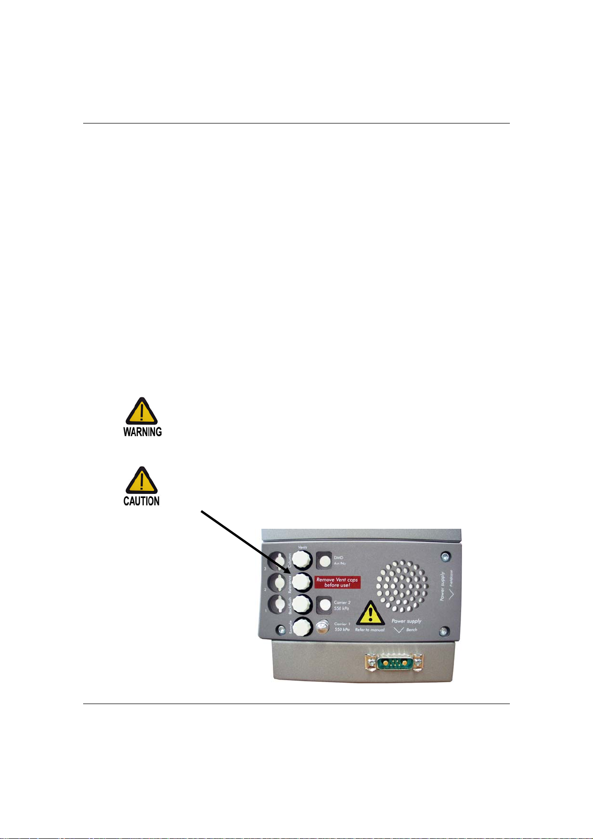
The instrument has been protected during shipment by protection caps.
Prior to operating, remove:
• At the back of the system all (plastic) caps (see picture below).
Varian, Inc. User Manual CP-4900 Micro-GC Page 9
Page 22

Introduction and Initial Operation
PACKING LIST
CP-4900 Micro-GC
Check the packing list to see if you have received all that you require.
Item Part number
External sample filter kit CP736729
Filters 5x for external filter assy. CP736467
CD-ROM user manual CP-4900 Micro-GC CP505532
Cable Dsub9 Male-Female 3 meter CP177138
Locking nut
CP420200 x 4
Male Luer
Front and back ferrule 1/16” SS x 2 CP4417
Capillary tubing SS 1/16” x 1.0 mm, 10 cm CP4008
Power supply 110V or CP49PWR110
Power supply 220V or CP49PWR220
Power supply 240V CP49PWR240
CP420100 x 4
Page 10 User Manual CP-4900 Micro-GC Varian, Inc.
Page 23

Introduction and Initial Operation
Accessories
Item Qty Part number
Spare filters (5 pieces) for external filter 5 CP736467
Manual CP-4900 Micro-GC (hard copy) 1 CP501265
Manual CP-4900 Micro-GC power supply (hard
copy)
Heated sample inlet elbow with frit 5 CP740434
Ethernet crossover cable 10 meter 1 CP740293
Ethernet crossover cable, 2 meter 1 CP740292
Combo card (Ethernet and Com ports), including 3
meter crossover cable (not for HUB)
Aux power car cigarette lighter DC adapter 1 CP740291
Charger for CP-4900 battery pack 1 CP740427
Battery pack NiMH (rechargeable) 1 CP740328
1 CP501267
1 CP740292
Micro Gasifier 110 Volt 1 CP740431
Micro Gasifier 220 Volt 1 CP740432
Micro Gasifier 240 Volt 1 CP740433
Genie 170 BTU filter complete 1 CP739535
Genie 101 BTU filter complete 1 CP739534
Genie 170 standard filter complete 1 CP739536
Genie 170 BTU membrane 1 CP739531
Genie 170 standard membranes 5 392590004
Genie 101 BTU standard membranes 5 392590005
Varian, Inc. User Manual CP-4900 Micro-GC Page 11
Page 24

Introduction and Initial Operation
INSTALLATION
Install Gas Regulators and Set pressures
Carrier gas supplied from cylinders should have a two-stage pressure assembly to
adjust the carrier gas pressure to 550 ± 10 % (80 ± 10 %). Set cylinder regulator
pressure to match the CP-4900 Micro-GC gas inlet pressure
Carrier_gas_connection on page 17).
(see
Carrier gas
The most commonly used carrier gas for the CP-4900 Micro-GC is either He or N2. The
recommended purity for carrier gas is 99.995% minimum.
Carrier_gas_connection on page 17
See
Connect to Power
First, connect the power connector to the CP-4900 Micro-GC, then plug the power cord
into an appropriate source of power.
Connect data handling peripherals
The CP-4900 Micro-GC must be connected to an external Workstation both to set up
the method and to acquire data.
Workstations and other data handling devices are connected to the cable connectors
inside the CP-4900 Micro-GC (see
• If CP-Maître Elite Workstation software with CP-4900 Micro-GC control is being
installed, follow the software installation instructions in the Workstation section of
this manual (see
• Hardware connection between the Workstation (computer) and CP-4900 Micro-GC
may be made via serial (RS232, standard) or Ethernet (optional). For additional
information, follow the links:
Cable_connectors on page 16.
Workstation_software on page 57).
Cable_connectors on page 16 for more details).
Communication_setup on page 67 and
Page 12 User Manual CP-4900 Micro-GC Varian, Inc.
Page 25

Introduction and Initial Operation
Sample
Connect the sample to the CP-4900 using the sample-in connector situated at the front
of the instrument (
chapter Sample Gas on page 18 for more important information!
Read
see front view on page 14).
Heated Sample line
To connect heated sample lines refer
to Heated Sample line chapter on page
20.
Turn power ON
Turn on the CP-4900 Micro-GC using the power switch on the lower front of the
instrument. The “READY” LED should light (after two minutes) when ready. (see
Front_view on page 14).
Factory default states and settings
Your CP-4900 Micro-GC is shipped from the factory with default settings. The following
is relevant information on the factory default states and settings:
• When the CP-4900 Micro-GC is turned on, the power LED will light up and the
system will begin the Flush cycle procedure. The Flush cycle is a 2-minute cycle in
which the various valves are activated and deactivated in order to flush the
entrapped air from the manifold, valves, and tubing.
• After the flush cycle is finished, the method (the default method in this case), which
was last active before the instrument was shutdown, is activated:
• All heated zones will be set at 30°C.
• The Detector filaments will be set to OFF.
If your system is supplied with a DMD (Differential Mobility Detector) detector all
settings are factory installed. The complete DMD method for the instrument (customer)
specific application is tested en installed inside the DMD.
Varian, Inc. User Manual CP-4900 Micro-GC Page 13
Page 26
Introduction and Initial Operation
INSTRUMENT OVERVIEW
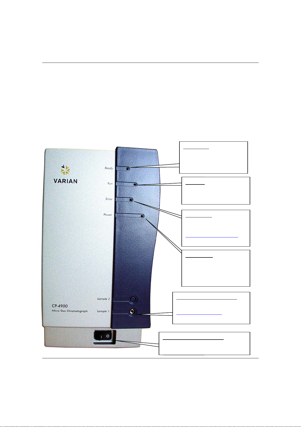
FRONT VIEW
READY led
Led OFF: System NOT ready
Led ON: System ready
RUN led
Led OFF: No run
Led blinking: Run in progress
ERROR led
Led OFF: No error
Led blinking: Error present
See here for the complete list on
page 126
POWER led
Led OFF: No power
Led ON: Power OK
Led blinking: Voltage < 10 Volt
SAMPLE 1 and SAMPLE 2
Sample gas inlet connector
See here for more details on page 18
POWER ON/OFF SWITCH
Switch the CP-4900 Micro-GC ON or OFF
Page 14 User Manual CP-4900 Micro-GC Varian, Inc.
Page 27

Introduction and Initial Operation
BACK VIEW
VENTS
DMD CONNECTOR
In DMD channel used as connector for
transport gas.
See here for more details on page 8
It is possible to connect long vent lines to these fittings in order to safely
guide hazardous fumes to a fume hood or other appropriate vent.
CARRIER 1 CONNECTOR
Carrier gas input connector
See here for more details on page 17.
POWER CONNECTOR
Power IN connector (male).
See here for more details on page 22
Varian, Inc. User Manual CP-4900 Micro-GC Page 15
Page 28

Introduction and Initial Operation
INSIDE VIEW
Open the cover and the cable connectors will be visible.
ASSIGN IP-ADDRESS BUTTON
Holding down this button during power-up will set
the “assign IP-address mode”
Assign_new_IP_address on page 70
See
ETHERNET
Ethernet RJ45 connector for Ethernet
installations.
See here for more details on page 60
COM 2 & COM 3
Optional RS232 (2-wire) and RS485 (4wire)- communication interface, only
available if Combo card is present.
See here for more details on page 39
Red led: Transmit data
Green led: Receive data
COM 1
RS232-communication interface.
See here for more details on page 39
ANALOG I/O
External Analog I/O signals.
See here for more details on page 40
DIGITAL I/O
Digital in and output signals, like start_stop,
ready_out, start_in and much more.
See here for more details on page 38
Page 16 User Manual CP-4900 Micro-GC Varian, Inc.
Page 29

Introduction and Initial Operation
CARRIER GAS CONNECTION
The carrier gas line is connected from a carrier gas connection to the CP-4900 MicroGC at the rear panel CARRIER GAS 1 or 2 port.
Do not use any kind of plastic tubing since air will diffuse through the tubing,
which may cause noisy baselines and decreased sensitivity. The metal
tubing should be clean for GC use. Buy either flamed or chromatographically
clean tubing.
Specifications for the carrier gas used on CP-4900 Micro-GC:
Pressure: 550 ± 10 % (80 ± 10 %)
Purity: 99.995% minimum
Dry and free of particles: CP-Gas Clean filters are recommended
CP-Gas Clean filters are recommended to remove any traces of moisture and oxygen.
For low-level analysis a better grade of carrier gas should be considered. The type of
analysis you want to perform determines the type of carrier gas used. The difference
between the relative thermal conductivity of the carrier gas and the sample components
should be as high as possible. Refer to the table for several relative thermal
conductivities.
Hydrogen 47.1 Ethane 5.8
Helium 37.6 Propane 4.8
Methane 8.9 Argon 4.6
Oxygen 6.8 Carbondioxide 4.4
Nitrogen 6.6 Butane 4.3
Carbon monoxide 6.4
Your CP-4900 Micro-GC is configured either for carrier gas He (or H
is configured for N
(or Ar). Make certain that the carrier gas selection in
2
the controlling Workstation corresponds to the carrier gas connected to
your CP-4900. Use carrier gas corresponding this configuration.
Changing type of carrier gas must only be carried out using the
mandatory procedure in the
Workstation software on page 74
If you are using hydrogen as carrier gas, pay particular attention to
possible leaks at connections inside and outside the CP-4900 Micro-GC
(use an electronic Leak Tester).
CP-Gas Clean filters are filled with nitrogen. If you are not using nitrogen
as the carrier gas, flush filters and gas lines after installation of a new
filter.
) or it
2
Varian, Inc. User Manual CP-4900 Micro-GC Page 17
Page 30

Introduction and Initial Operation
SAMPLE GAS
The CP-4900 Micro-GC is an analyzer built for the analysis of gases and vapors only.
You are advised to prepare a non-condensing gaseous samples standard sample for
routine check up of the instrument. Sample pressure should be between 0-100 kPa (015 psi), the temperature between 0 and 40°C ± 5°C of the analyzer ambient
temperature and it must be filtered, preferably through a 5 μm filter. Varian, Inc.
ALWAYS recommends the use of the external filter kit part number CP736729.
Click here for more
Liquids will seriously damage the instrument and should be avoided!
Handling a sample
If possible, filter and dry the sample before introducing it to the Micro-GC. It is advised
to use an External Sample Filter Unit between the injector and the sampling device.
The Filter, male must be hand tightened into the Filter Female, followed by a 1/8th turn
with a 7/16" wrench. The arrow on the Filter Female should be directed towards the
Fingertight Fitting.
Whenever possible remove moisture from samples introduced to the
CP-4900 Micro-GC.
Unheated Injector Systems
details about the heated sample line on page 20.
Replace the External Filter Unit on page 11 dat regular intervals.
Page 18 User Manual CP-4900 Micro-GC Varian, Inc.
Page 31

Introduction and Initial Operation
Heated Injector Systems
Varian, Inc. User Manual CP-4900 Micro-GC Page 19
Page 32

Introduction and Initial Operation
HEATED SAMPLE LINE
A heated sample line is always combined with a heated injector.
A heated injector and sample line is an option for a channel unit and is chosen in case
condensable samples need to be analyzed and condensation in th e sample lines needs to be
prevented.
The heated sample and injector can be controlled between 30°C and 110°C (see also
Maître Elite on page 98 Workstation).
Connect a heated sample line
Before connecting a heated sample line, allow the sample line heater to cool
down to ambient temperature. The metal surfaces of the sample line heater
are very hot and could burn your skin.
- Open the side panel, the heater will be visible.
Sample line heater
- Remove the insulation.
CP-
Page 20 User Manual CP-4900 Micro-GC Varian, Inc.
Page 33

Introduction and Initial Operation
- The sample line connector will be visible.
- Connect the sample line.
Insulate the sample line coming into the CP-4900, this to prevent damage to the
in/out coming cables.
Must be insulated
Varian, Inc. User Manual CP-4900 Micro-GC Page 21
Page 34

Introduction and Initial Operation
POWER
The CP-4900 Micro-GC requires 12.0 VDC, 130W maximum.
Refer to the User manual power supply for more information part number CP501267.
Only use the power supply that has been supplied with the instrument.
SHUT DOWN PROCEDURE
When the instrument is shut down for more then a few days please,
carry out the procedure mentioned below
Create a method for all channels with the following settings:
• Filaments switched OFF.
• Column temperature set at 30°C.
• Injector temperature set at 30°C.
• Pressure set at 50 KpA.
• Wait until the temperature of the column and injector is < 40°C (to protect the column),
before switching off the Micro-GC.
• Remove the carrier gas tubing and plug all the vents/carrier gas connections with 1/8”
brass nut or plastic cap.
• When the instrument is going to be used again then follow the procedure
on page 23
Page 22 User Manual CP-4900 Micro-GC Varian, Inc.
Page 35

Introduction and Initial Operation
LONG STORAGE RECOVERY PROCEDURE
Follow the recovery procedure below if your CP-4900 Micro-GC has been
stored for a long period of time
• Remove the 1/8” brass nuts & plastic caps from all the vents/carrier gas
connections.
• Connect carrier gas tubing and apply pressure on the CP-4900 Micro-GC,
according the pre-installation requirements.
• Wait, at least 10 minutes, before switching ON the Micro-GC.
• Check immediately if the detector filaments are switched OFF, switch OFF if
necessary (see
• Set the column(s) temperature to the maximum allowed temperature
(160 °C or 180 °C depending on the column module).
• Condition the column module, preferably overnight. This will ensure that all
the water has been removed from the column module and no damage will
occur to the TCD filaments.
Method_setup on page 90 for more details).
Varian, Inc. User Manual CP-4900 Micro-GC Page 23
Page 36

Introduction and Initial Operation
INITIAL OPERATION
A test method has been provided. This method has been designed to determine if the
instrument is functioning properly and comes together with test chromatograms on
which the test conditions are stated.
If you ordered a Molsieve column, make sure it is conditioned before use.
conditioning_Molsieve_columns on page 31 for parameters.
See
INITIAL RUN
SETTING UP THE TEST METHOD
To enter the method parameters, refer to the
data-handling package manual.
Send the instrument parameters from the data-handling package software to the MicroGC. You can watch the CP-4900 Micro-GC status in the
85.
method set-up portion on page 90 of the
instrument status tab on page
INJECTING THE SAMPLE
Connect the sample by means of a 1/16" line
to the CP-4900 Micro-GC. You are advised
to put an external 5 μm filter between the
sample and the CP-4900 Micro-GC for
additional filtering (see
18 for more details).
Press the START button to begin analysis.
Following are a few results on commonly
used columns. CP-Sil 5 CB and CP-Sil 19
CB, HayeSep A and Molsieve. The sample is
natural gas, which provides a convenient
standard for testing the instrument in any
configuration of these columns.
Sample_Gas on page
0.77 % Nitrogen
N
2
CH4 89 % Methane
C2H6 8 % Ethane
C3H8 1 % Propane
IC4H10 0.14 % Isobutane
NC4H10 0.2 % N-butane
IC5H12 0.007 % Isopentane
NC5H12 0.001 % N-pentane
Page 24 User Manual CP-4900 Micro-GC Varian, Inc.
Page 37

Introduction and Initial Operation
y
COLUMN CP-SIL 5 CB 6 METER UNHEATED
Instrument parameters
Column temperature : 50°C
Injector temperature : NA
Column pressure : 150kPa (21PSI)
Sample time : 30s
Injection time : 40ms
Run time : 60s
Detector sensitivit
: Auto
ID Component Concentration
Peak identification
1 Composite Balance
2 Ethane 8.1%
3 Propane 1.0%
4 i-Butane 0.14%
5 n-Butane 0.20%
The natural gas components, mostly hydrocarbons, separate in the same order on the
non-polar and medium-polar CP-Sil CB columns. Nitrogen, methane, carbon dioxide,
and ethane are not separated on these columns. They produce a composite peak. For
separation of these components a HayeSep A column is advised.
Varian, Inc. User Manual CP-4900 Micro-GC Page 25
Page 38

Introduction and Initial Operation
y
COLUMN CP-SIL 5 CB 4 METER HEATED
Instrument parameters
Column temperature : 50°C
Injector temperature : 110°C
Column pressure : 150kPa (21PSI)
Sample time : 30s
Injection time : 40ms
Run time : 30s
Detector sensitivit
: Auto
ID Component Concentration
1 Composite Balance
2 Ethane 8.1%
3 Propane 1.0%
4 i-Butane 0.14%
5 n-Butane 0.20%
Peak identification
Page 26 User Manual CP-4900 Micro-GC Varian, Inc.
Page 39

Introduction and Initial Operation
y
COLUMN CP-SIL 5 CB 8 METER HEATED
Instrument parameters
Column temperature : 50°C
Injector temperature : 110°C
Column pressure : 150kPa (21PSI)
Sample time : 30s
Injection time : 40ms
Run time : 60s
Detector sensitivit
: Auto
ID Component Concentration
1 Composite Balance
2 Ethane 8.1%
3 Propane 1.0%
4 i-Butane 0.14%
5 n-Butane 0.20%
Peak identification
Varian, Inc. User Manual CP-4900 Micro-GC Page 27
Page 40

Introduction and Initial Operation
y
COLUMN CP SIL13CB TBM 12 METER HEATED
Instrument parameters
Column temperature : 40°C
Injector temperature : 50°C
Column pressure : 250kPa (38PSI)
Sample time : 30s
Injection time : 255ms
Run time : 80s
Detector sensitivit
Page 28 User Manual CP-4900 Micro-GC Varian, Inc.
: Auto
ID Component Concentration
1 Methane Balance
2 TBM 6.5ppm
Peak identification
Page 41

Introduction and Initial Operation
y
COLUMN HAYESEP 40CM HEATED
Instrument parameters
Column temperature : 50°C
Injector temperature : 110°C
Column pressure : 150kPa (21PSI)
Sample time : 30s
Injection time : 40ms
Run time : 60s
Detector sensitivit
: Auto
ID Component Concentration
Peak identification
1 Nitrogen 0.77%
2 Methane Balance
3 Ethane 8.1%
The HaySep A column separates oxygen, methane, carbon dioxide, ethane, acetylene,
ethylene, and selected sulfur gases. Nitrogen coelutes with oxygen. Components with a
higher molecular weight than propane have long retention times on this column.
Maximum allowable column temperature: 160 °C
Varian, Inc. User Manual CP-4900 Micro-GC Page 29
Page 42

Introduction and Initial Operation
y
COLUMN MOLSIEVE 5Å 20 METER UNHEATED
Instrument parameters
Column temperature : 40°C
Injector temperature : NA
Column pressure : 200kPa (28PSI)
Sample time : 30s
Injection time : 40ms
Run time : 210s
Detector sensitivit
: Auto
ID Component Concentration
1 Neon 18ppm
2 Hydrogen 1.0%
3 Argon 0.2%
4 Oxygen 0.2%
5 Nitrogen 0.2%
Peak identification
The Molsieve 5Å column is designed to separate: hydrogen, carbon monoxide,
methane, nitrogen, oxygen, and some noble gases. Higher molecular weight
components have much higher retention times on this column.
Page 30 User Manual CP-4900 Micro-GC Varian, Inc.
Page 43

Introduction and Initial Operation
Conditioning of Molsieve columns
On a properly activated column nitrogen and oxygen will be very well separated.
However, in time you will find that these two peaks will start to merge together. This is
caused by water, present in the sample or carrier gas, adsorbing to the stationary
phase. To restore the columns efficiency it will suffice to raise the oven temperature to
180 °C (max. column oven temperature) and, with the normal operating pressure on the
column head, leave it to condition for about an hour. You are advised to switch the
detector filaments off during this period. After reconditioning you can test the column
performance by injecting plain air. If you have a proper separation between nitrogen
and oxygen again the column separation power has been restored. If the CP-4900
Micro-GC's frequency of use is very high, you might adopt a standard reconditioning
procedure of leaving the instrument with the oven temperature at 180°C overnight. The
longer the re+onditioning period the better the column performance without damage.
Varian, Inc. User Manual CP-4900 Micro-GC Page 31
Page 44

Introduction and Initial Operation
y
COLUMN PPQ 10 METER HEATED
Instrument parameters
Column temperature : 150°C
Injector temperature : 110°C
Column pressure : 150kPa (21PSI)
Sample time : 30s
Injection time : 40ms
Run time : 50s
Detector sensitivit
: Auto
ID Component Concentration
1 Composite Balance
2 Ethane 8.1%
3 Propane 1.0%
4 i-Butane 0.14%
5 n-Butane 0.20%
Peak identification
Page 32 User Manual CP-4900 Micro-GC Varian, Inc.
Page 45

Reference
REFERENCE
INSTRUMENT DESCRIPTION
CARRIER GAS
The Varian, Inc. CP-4900 Micro-GC is configured for the use with either He (or H
(or Ar).
Having chosen one option definitely rules out the use of the other without the
instrument undergoing internal changes prior to any switching of carrier gas
type.
It is recommended to use gases with a minimum purity of 99.995%. Since the injection
valve is operated pneumatically, there is a limit of 550 ± 10 % (80 ± 10 %) to the main
gas supply.
Your CP-4900 Micro-GC is configured either for carrier gas He (or H
configured for N
(or Ar). Use the carrier gas type, for which your instrument
2
is configured, otherwise the detector filaments can be damaged.
) or N2
2
) or it is
2
Varian, Inc. User Manual CP-4900 Micro-GC Page 33
Page 46

Reference
GAS CLEAN UNIT
(OPTIONAL)
Micro-
electronic
gas control
(EGC)
Injector Column &
reference
Detector
(TCD)
CARRIER GAS
SAMPLE
IN OUT
MICRO ELECTRONIC GAS CONTROL (EGC)
The CP-4900 Micro-GC has built-in Micro EGC regulators that can be adjusted to get a
constant or programmed pressure control, which result in a constant or programmed
flow through the injector, column and detector. The pressure range of the Micro EGC is
between 50-350 kPa (7 - 49 Psi). This pressure sets a continuous flow of carrier gas of
about 0.2-4.0 mL/min.
A typical pressure rise is 200 kPa/min, which will give a significant pressure increase
during the run, without excessive baseline disturbance. In most cases baseline
subtraction may improve the quality of chromatograms that suffer from baseline drift.
INJECTOR
The injector has a built-in 10μl sample loop that is filled with the gaseous sample. The
pressure of the sample should be between 0-100 kPa (0-15 psi) and the sample
temperature within 5-40 °C ±5 °C of the analyzer.
By activating the START option within the data-handling package, a vacuum pump will
draw the gas sample through the loop and then the injector will inject the gas sample
from the sample loop into the gas stream. The minimum pressure required by the
injector is 550 ± 10 % (80 ± 10 %). A typical injection time is 40 milliseconds (ms). This
equals an average injection volume of 200 nL. Injection time will be rounded to a
multiple of 5 ms. A practical minimum value is 40 ms.
In most cases a value of 0 - 20 milliseconds will result in no injection.
COLUMN/REFERENCE
VENT
Page 34 User Manual CP-4900 Micro-GC Varian, Inc.
Page 47

Reference
COLUMN
A variety of column configurations are possible on the CP-4900. The columns you
require for your specific analysis have been installed at our factory. Other configurations
are, of course, possible, but changing the column modules is a delicate matter that can
only be handled by one of our service engineers. Table I shows several standard
columns as supplied in the CP-4900 Micro-GC and selected applications. Other
columns are available by contacting Varian, Inc.
Column Main applications
Molsieve 5Å PLOT Hydrogen (H2), oxygen (O2), nitrogen (N2), methane (CH4),
carbon monoxide (CO), noble gases (Kr, Xe, Ne)
HayeSep A Air, methane (CH4), carbon dioxide (CO2), ethylene (C2H4),
ethane (C
CP-Sil 5 CB Can separate all components analyzed on the CP-Sil 19 CB
stationary phases. Has higher capacity and is ideally suited
for natural gas analyses.
), acetylene (C2H2), natural gas
2H6
CP-Sil 19 CB Natural gas, vapors of common solvents, EPA volatile prior-
ity pollutants. Separation primarily by boiling point where the
last eluting compound has the highest boiling point.
CP-WAX 52 CB Polar compounds such as alcohol's. Separation based on
polarity. Also for aromatic compounds
Table I Some Varian, Inc columns and applications
All columns except the HayeSep A and MES (TCEP) column can be used up
to 180 °C, the maximum temperature of the column oven. The HayeSep A
will deteriorate above 160 °C. Exceeding this temperature will cause the
column to lose efficiency instantly and the column module will need
replacement.
Varian, Inc. User Manual CP-4900 Micro-GC Page 35
Page 48

Reference
DETECTOR
TCD
The CP-4900 Micro-GC is equipped with a thermal conductivity detector (TCD). This
detector responds to the difference in thermal conductivity between the carrier gas and
the sample components. The construction of a TCD is such that the changing thermal
conductivity of the carrier gas stream, due to components present, is compared to the
thermal conductivity of a constant reference gas stream.
DMD
The Differential Mobility Detector, DMD, is fully integrated into a CP-4900 Analytical
channel.
Differential Mobility Detection is an advanced form of Ion Mobility Spectroscopy (IMS). It
uses a drift tube under atmospheric and thermally constant conditions. See for more
details chapter
The difference mobility detector on page 42.
Page 36 User Manual CP-4900 Micro-GC Varian, Inc.
Page 49

Reference
IN/OUTPUTS
The CP-4900 Micro-GC has several in/output ports accessible insid e the instrument for
interfacing with external devices.
Open the cover.
At the front of the CP-4900 Micro-GC, the external device connectors will be visible.
Close the cover after connecting the cables!
Varian, Inc. User Manual CP-4900 Micro-GC Page 37
Page 50

Reference
EXTERNAL DIGITAL I/O
Connection between CP-4900 Micro-GC and external devices is made with the
appropriate cable to the External Digital I/O port (see also
117).
CP-4900
*
Relay contacts maximum 24 V olt 1 Ampere
Ready/not ready signal
The Instrument Ready/not Ready output will follow instrument status (Ready LED in the
front of the instrument).
Difference between Workstation Software packages,
GND
*
*
*
*
Pin
1
2
3
4
5
6
7
8
9
10
11
12
13
14
15
16
17
18
19
20
21
22
23
24
25
External Digital I/O
Digital IN1 (not definied)
Digital IN2 (not definied)
Digital OUT1 (not definied)
Digital OUT2 (not definied)
Not used
Start-IN
External Ready-IN
External system reset
Not used
OUT
OUT
OUT
OUT
Reserved
+5 VDC out (electronic fused max 500 mA)
+12 VDC out ( electronic fused max 500 mA)
Relay 1
Relay 2
Start
Ready/not ready
Micro-GC will only start in external ready mode when
Start-IN detects a contact closure pulse
500 ms contact closure when injection will take place
click here on page 41.
External_devices on page
Page 38 User Manual CP-4900 Micro-GC Varian, Inc.
Page 51

Reference
COMMUNICATION PORTS (COM)
CP-Maître Elite workstation is a software package for data collection and CP-4900
Micro-GC control. All instrument parameters can be adjusted from CP-Maître Elite
workstation. The instrument communicates serially with the computer via an RS-232
port (COM1) accessible inside the instrument. (see also
Serial_communication on page
59).
In the table below an overview is given of the communication possibilities.
Function Standard
(without I/Ocard)
COM1 RS-232-interface RS-232-interface RS-232-interface RS-232-interface
COM2 - RS-232-interface - RS-232-interface
COM3 - RS-485-interface - RS-485-interface
Ethernet - - 10Mbit 10Mbit
Video output - - - VGA (not used)
COM 1
Pin
RS-232
DCD
1
TXD
2
RXD
3
DTR
4
GND
5
DSR
6
CTS
7
RTS
8
RI
9
Optional
COM-card
placed
data carrier detect
transmitted data
received data
data terminal ready
ground
data set ready
clear to send
request to send
ring indicator
COM 2
Optional
Ethernet-card
placed
Pin
1
RXD
2
TXD
3
4
GND
5
6
RTS
7
8
CTS
9
RS-232
Optional
COMBO-card
placed
received data
transmitted data
ground
request to send
COM 3
Pin
1
2
3
4
5
6
7
8
9
RS-485
RXA(+)
RXB(-)
TXB(-)
TXA(+)
Difference between Workstation Software packages, click here on page 41.
Varian, Inc. User Manual CP-4900 Micro-GC Page 39
Page 52

Reference
EXTERNAL ANALOG I/O
This external analog I/O port can handle six (6) analog inputs (input 0-10 Volt)
The User Interface receives this analog information, and translates this information into
actions to be taken by the local user interface and/or events/data to be shown/stored in
the remote user interface (see also
CP-4900
GND
Analog GND
Pin
External_devices on page 117).
1
2
3
4
5
6
7
8
9
10
11
12
13
14
15
+15 VDC out (electronic fused max 100 mA)
-15 VDC out (electronic fused max 100 mA)
+5 VDC out (electronic fused max 500 mA)
+12 VDC out (electronic fused max 500 mA)
External Analog I/O
EXT-Analog IN1
EXT-Analog IN2
EXT-Analog IN3
EXT-Analog IN4
EXT-Analog IN5
EXT-Analog IN6
Page 40 User Manual CP-4900 Micro-GC Varian, Inc.
Page 53

Reference
DIFFERENCE BETWEEN WORKSTATION SOFTWARE PACKAGES
Communication Ethernet and RS232 Ethernet only
IP Settings BootP/RS232 BootP/RS232
Com-1 RS232 Not available
CP-Maitre Elite Galaxie
Com-2
Com-3 Not available Not available
Analog I/O Capturing Not available
Digital I/O
Relay Control
Stream selection on
Com-2
External start in: Yes
External Ready: Yes
Timed Relay: Yes
Alarm Relay: Yes
Extension Box: Yes
Stream selection on
Com-2 *
External start in: Yes
External Ready: Yes
Timed Relay: Yes
Alarm Relay: Yes
Extension Box: No
* Only one Vici valve possible in Galaxie
Varian, Inc. User Manual CP-4900 Micro-GC Page 41
Page 54

Reference
THE DIFFERENTIAL MOBILITY DETECTOR
GENERAL
WARNING:
RADIATION SOURCE
For details about procedures governing the handling, leak testing, repair,
storage, shipping and maintenance of records for the Ni
radioactive sealed source please refer to the Ni
General functionality
Varian has extended its CP-4900 Micro Gas Chromatogra phy product line with a new
detector. The Differential Mobility Detector, DMD, integrated into the CP-4900 chassis is
a joint development of Sionex Corporation and Varian Instruments.
Differential Mobility Detection is an advanced form of Ion Mobility Spectroscopy (IMS). It
uses a drift tube under atmospheric and thermally constant conditions. The advantage
over IMS is that DMD uses additional sets of RF modulation voltages, which results in
selective performance, which is tuneable depending on the compounds of interest and
the matrix.
Ions generated by a Ni63 radioactive ionization source are transported through a drift
tube by means of a high velocity transport gas, usually Zero-Air or Nitrogen. The drift
tube basically consists of two parallel plates, approximately 500 microns apart. Over
these plates a RF modulated electric field is applied by setting a fixed Voltage of 2-500
Volts/cm and a Scanning Voltage (or Compensation Voltage). The RF modulation
frequency is 1.3 Megahertz.
This detector contains a Ni63 beta-emitting radioactive
isotope plated onto a metallic foil for ionization of the
carrier gas.
63
Radiation Safety Manual.
63
DMD detector as a
Isolation results from the interaction between the ion and the net applied field that
alternates between high and low electric field strength. Trajectory of the target ions will
be tuned so that the ions of interest straight through the filter without colliding with the
electrode plates, when they would be neutralized and not detected. The Compensation
Voltage is used for ‘tuning’ the trajectories of ions in order to get the ‘desired’ ions
towards the detector.
Page 42 User Manual CP-4900 Micro-GC Varian, Inc.
Page 55

Reference
Figure: DMD set-up showing different voltages applied.
As illustrated in Figure 1, the net voltage applied results from three independent
settings:
1. A fixed voltage, or RF-Voltage,
2. A scanning voltage, also referred to as Compensation Voltage,
3. A RF modulated voltage.
Varian, Inc. User Manual CP-4900 Micro-GC Page 43
Page 56

Reference
Figure 2:Separation principle of DMD
As illustrated in Figure 2, the DMD is equipped with two detectors, one for positive ions
and one for negative ions. Yet, the data produced by the DMD show a ‘normal’ twodimensional representation as the system will be ‘tuned in time’ to detect certain
species by setting compensation voltages to accommodate transmission of the
compound of interest in that particular part of the chromatogram. This ‘time-segmented’
detection thus leads to maximum selectivity for the application of interest as the matrix
is eliminated. The application specific method is saved inside the DMD hardware.
CP-4900 Micro-GC DMD Channel
The DMD channel is always located in the last position (against the backpanel)
The CP-4900 firmware recognises the DMD channel as a detector only, and
automatically sets the controls accordingly.
Position 2 DMD channel
Page 44 User Manual CP-4900 Micro-GC Varian, Inc.
Page 57

Reference
A complete instrument, the CP-4900 DMD consists of a basic cabinet, a column module
with its pneumatic system, its standard µ-TCD and an additional DMD. The standard
channel’s µ-TCD output is in series with the DMD inlet via a heated transfer line. The
temperature of this heated transfer line is controlled from the DMD electronics.
From a control point of view, the DMD has no control of a column temperature or
column head pressure or the optional injector temperature as needed for the GC
channel. No carrier gas type needs to be selected in the configuration.
Furthermore, the DMD method is factory tuned and ready to perform the appropriate
application. This requires the Micro-GC method to be identical throughout its use with
respect to chromatographic column and settings.
GENERAL OPERATION
Within the workstation package, the DMD will be handled as a separate channel. With
respect to the operation of the DMD note the following:
• In instrument configuration, selection of carrier gas type and heated injector has
been removed.
• In method development for the DMD channel, GC-channel specific information has
been left out. Instead, the Transfer line temperature and the detector tuning
capabilities are added.
• In instrument status for the DMD channel, GC-channel specific information has
been left out. Instead, the Transfer line temperature and the detector tuning
capabilities are added.
Tuning the DMD
The complete DMD method for the instrument specific application has been tested and
is loaded inside the DMD. Generally no modification or changes are required in case
the factory-supplied method is used throughout.
In case of a suspected misalignment of the method, where retention time or
compensation voltage may be out of tune, a tuning run may be needed.
Please contact for more information your local Varian Inc. subsidiary or Varian, Inc.
representative.
Varian, Inc. User Manual CP-4900 Micro-GC Page 45
Page 58

Reference
Networking Basics
This section will help you to understand networking in a global way.
THE NETWORKING MODELS
Peer-to-peer
• Also known as the Workgroup Model.
• Computers are referred to as Workstations.
• Workstations share one or more resources in a decentralized way.
• There are no servers in peer networking.
• Workstations are all equal on the Network.
• Easy and inexpensive to maintain.
• Ideal for the small lab, office with 2-10 computers.
Client/Server
• One or more Servers that run a Network Operating System (NOS).
• A NOS is a requirement for high volume or highly secure networks.
• Users must authenticate on the network before resources are made
available.
• Difficult and expensive to maintain.
• Used for larger office networks 10+ Computers.
Different types of networks
Star Topology
• Nodes are connected by branches.
• Central Device is usually a hub or Switch.
• Central Device controls the communication
of each node.
Page 46 User Manual CP-4900 Micro-GC Varian, Inc.
Page 59

Reference
Bus Topology
• All Nodes are connected to a central link.
• Information is placed upon the link by any
given node.
• Sender and recipient information is
broadcasted to all attached devices.
Ring Networks
• Known as “Token Ring” or “Passing Ring”.
• The media forms a closed loop.
• Each node checks the data as it passes by.
DIFFERENT CABLE TYPES
The chosen cable type depends on the required distance, speed, interference and
security.
Coaxial
• Single Copper connector enclosed by protective braided copper shield.
• Widest implementation is broadband access to cable TV.
• Must have a terminator at each end.
Varian, Inc. User Manual CP-4900 Micro-GC Page 47
Page 60

Reference
Coaxial RG-58
• 10Base2, also known as Thin-net.
• Maximum Speed is 10Mbps.
• Maximum Length is 185 meters.
• The Network card is usually directly connected to the 10Base2 cable with a
T-Connector.
• T-Connector is also known as BNC (British Naval Connector).
Twisted Pair
• Flexible and easy to work with.
• 4 pairs of twisted wire inside a PVC or plenum Jacket.
• RJ45 connectors on each end.
• Plenum cable is recommended when running in ceiling or walls.
When connecting two nodes with a single twisted
pair cable, it must have the transfer and receive
lines crossed. This is referred to as a crossover
cable.
There are several different categories of twisted pair, both unshielded (UTP) and
Shielded (STP) - category 5 is recommended:
Category Cable type Application
1 UTP Analog voice-telephone
2 UTP Digital voice- 1 Mbps data
3 UTP/STP 16 Mbps data
4 UTP/STP 20 Mbps data
5 UTP/STP 100 Mbps data
6 UTP/STP 155 Mbps data (proprietary)
7 UTP/STP 1000 Mbps data (proprietary)
Page 48 User Manual CP-4900 Micro-GC Varian, Inc.
Page 61

Reference
PROTOCOLS
A protocol is a set of rules that govern how computers send and receive information.
Different Types of Protocols:
AppleTalk, ATM, Banyan Protocols, CDPD, DECnet Protocols, Frame Relay, GPRS,
H.323, IBM Protocols, ISDN, ISO Protocols, LAN Data Link Layer Protocols, MPLS
Novell Protocols, PPP Suite, Bridge/Router Internetworking Protocols, SNA, SS7
Suite Sun Protocols, Tag Switching Protocols, TCP/IP Suite, UMTS Telephony, V5,
Voice over IP#(VoIP), WAP, X.25, XNS
The Internet Protocol Suite
• Developed to allow cooperating computers to share resources across a network.
• TCP and IP are the two best-known protocols in the Internet Protocol Suite.
• Other protocols / services are FTP, Remote Login (Telnet), Mail, SMTP.
IP Addresses
• Uniquely identify a computer on the Network / Internet.
• Are made up of four 8-bit numbers and each of these numbers are separated by a
point.
• Each of the 8-bit numbers can represent a decimal value of 0-255.
• Each part of an IP address can only be in that range (e.g., 198.12.253.98).
The Internet protocol suite
Starting IP Ending IP Subnet Mask Type
0.0.0.0 255.255.255.255 N/A Public
10.0.0.0 10.255.255.255 255.0.0.0 Private
172.16.0.0 172.31.255.255 255.255.0.0 Private
192.168.0.0 192.168.255.255 255.255.0.0 Private
Note: never use 0.0.0.0. or 255.255.255.255
Varian, Inc. User Manual CP-4900 Micro-GC Page 49
Page 62

Reference
NETWORKING DEVICES (HUBS, SWITCHES, AND ROUTERS)
Hubs and switches are…
• Different types of network equipment that connect devices.
• Different in the way that they pass on the networking traffic they receive.
• Often used in one network where the hubs provide more ports, and the switch
divides the network into smaller, less congested sections.
Hubs
• Pass on (repeats) all the information it receives to all other attached devices.
• Can be used to extend the network.
• Pass on traffic to the network regardless of the intended destination.
• Result in a lot of redundant and unnecessary traffic sends across a network.
• Ideal for smaller networks (less than 30 devices).
Page 50 User Manual CP-4900 Micro-GC Varian, Inc.
Page 63

Reference
Switches
• Control the flow of network traffic based on the address information in packets.
• Learn which devices are attached to its ports switches.This allows simultaneous
connections across the switch improving speed.
• Reduces the amount of unnecessary traffic.
• Is in fact a “Smart” device, which is able to learn.
• Is a necessity when networks get larger (more than 50 users).
Varian, Inc. User Manual CP-4900 Micro-GC Page 51
Page 64

Reference
Routers
• Connect different networks together.
• Used to provide a link between networks with different physical connections
(cables).
• Provide a link between networks with a different logical connection (protocols).
• Consist of at least two network interface cards.
• Don’t have to be a black box, but could also be a regular PC with routing software.
Page 52 User Manual CP-4900 Micro-GC Varian, Inc.
Page 65

Reference
CP-4900 MICRO-GC AND NETWORKS
Network Requirements of the CP-4900 Micro-GC
• Customer Cable type should be Cat3 or Cat5 UTP / STP.
• Customer network should comply with Standard Ethernet (IEEE 802.3).
• The network must have either 10BASE-T or 10/100BASE-TX compatible HUB or
Switch.
• TCP-IP should be used on the network.
Varian, Inc. User Manual CP-4900 Micro-GC Page 53
Page 66

Reference
FAQ (FREQUENT ASK QUESTIONS)
Q: Can I connect the Micro-GC to my Network?
A: Yes, if the network is standard Ethernet and uses TCP-IP with UTP cabling.
Q: I’m using a DHCP server; can I use this to assign the GC with an IP-Address?
A: No, The GC works with static IP-addresses only, so an IP-address will have to be
reserved on the DHCP server and marked as static.
Q: How do I assign the GC with an IP-address?
A: Connect the GC via a UTP crossover cable to the pc running Workstation software.
Then define the network-settings, and restart the GC with the Service button
pushed.
Q: Are the network settings saved if the GC is restarted, or with loss of power?
A: Yes, the Network Settings of the GC are stored in Flash Memory, and will not be
erased at loss of power.
Q: Can I control my Micro-GC from anywhere in the world via the Internet?
A: Yes, if the customer network is designed for this, and has Internet access or remote
access facilities (the ports 4900,4901 and 4902 must be open).
Page 54 User Manual CP-4900 Micro-GC Varian, Inc.
Page 67

Reference
GLOSSARY OF NETWORK TERMS
The following brief glossary of terms may be useful:
BNC connector
This is a bayonet style connector used for a two-conductor style hardware connection.
BNC connectors are used with the CP-3800 GC.
Crossover Cable
A cable is used to connect two, and only two, Ethernet devices together.
Domain
This is one of several settings that reside within the TCP/IP configuration that identifies
paths that are used to establish connections with Ethernet devices. The Domain is an IP
address.
Ethernet Address
This is a unique identifier that every Ethernet communication device has assigned to it.
Typically, the Ethernet address cannot be changed and is the permanent way of
identifying a particular hardware device. The Ethernet address consists of 6 pairs of
hexadecimal digits.
Gateway
This is one of several settings within the TCP/IP configuration that identifies paths that
are used to establish connections with Ethernet devices. The Gateway is assigned an
IP Address.
Host name
The host name is an alternate way of identifying a device that is friendlier to people.
Frequently the host name and the IP address may be used interchangeable.
Hub
A device that allows many Ethernet devices to be interconnected. Several hubs may be
interconnected to increase the number of Ethernet connections. For 10Mbits/second
network connections (10BaseT), no more than four (4) hubs may be connected in
series. For 100M bits/seconds network connections (100BaseT), no more then two
hubs may be connected in series.
IP Address
This is a unique number for each Ethernet device within the set of connected devices.
Two PCs may have identical IP addresses so long as they are not interconnected to
each other either through the Internet. The IP Address consists of a series of four sets
of decimal numbers (between 1 and 255) that provide routing information used by the
TCP/IP protocol to establish a reliable connection. Without the IP Address,
communications would be bogged down trying to establish conne ctions to Ethernet
addresses at unknown locations.
Varian, Inc. User Manual CP-4900 Micro-GC Page 55
Page 68

Reference
Patch Cable
A cable that is used to connect Ethernet devices to hubs, switches, or your company
network.
RJ45 Connector
This is a telephone jack style connector used for a Universal Twisted Pair (UTP)
hardware connection for 10/100BaseT Ethernet connections.
RJ45-style connectors are used by the CP-4900 Micro-GC.
TCP/IP
An international standard protocol used by the Internet. We use this protocol for
communication to the CP-4900 Micro-GC. You may find several network protocols,
such as IPX/SPX and NetBEUI, installed on you computer.
Page 56 User Manual CP-4900 Micro-GC Varian, Inc.
Page 69

Reference
Workstation software
CONTROL INSTRUMENT
The CP-4900 Micro GC is standard equipped with a RS232 port for serial control on page 59 of
the instrument.
Ethernet control on page 60 (TCP/IP) is optional and requires an extra Ethernet card inside the
CP-4900.
Even if the instrument is equipped with Ethernet it is possible to control the instrument serially.
In that case the instrument will accept the first incoming connection type (serial or Ethernet) and
will lock the other connection type. There can never be a connection on the two different ports
at the same time.
Varian, Inc. User Manual CP-4900 Micro-GC Page 57
Page 70

Reference
CP-MAITRE ELITE
CP-Maitre Elite cannot
Multiple CP-4900s must be controlled serial or Ethernet, not a mixture of these two.
The maximum number of CP-4900s controlled by serial communication is two.
For Ethernet this is limited by your license.
The CP-4900 driver scope
control two CP-4900 micro GCs with different connection types.
Page 58 User Manual CP-4900 Micro-GC Varian, Inc.
Page 71

Reference
SERIAL COMMUNICATION
To control the CP-4900 Micro-GC via serial communication, just connect the serial cable
(supplied with the instrument) to a free serial port of your computer configured as RS232, and
plug the other side into port COM1 of the CP-4900 (see
Avoid cable lengths longer than 15 meter while this can cause communication
problems due to high communication speed (baud rate 115200 bits/sec).
The maximum number of CP-4900 Micro-GCs controlled by serial communication is
two. Choose Ethernet communication in case more than two CP-4900s must be
controlled by one computer or setup a second computer with CP-Maitre Elite
installed. If RS485 is required, an RS232-RS485 converter (optional) must be used.
RS485 is only possible via two RS232-RS485 converters, one on Workstation
(computer) side and either one at CP-4900 side on Com1.
Inside View on page 16).
Varian, Inc. User Manual CP-4900 Micro-GC Page 59
Page 72

Reference
ETHERNET COMMUNICATION
An Ethernet crossover cable (RJ-45 connector) is included with the Ethernet option.
The crossover cable must be used to control the CP-4900 Micro-GC in a peer-to-peer
communication (see
This requires IP addresses in the same range for computer and Micro-GC. Only the most right
IP segment must be different.
In case both the computer as well as the CP-4900 are connected to a (local) network this cable
cannot be used for control of the Micro-GC.
However this crossover cable must be used if a new IP address has to be assigned to the
Micro-GC. Once the IP address is assigned you can disconnect the crossover cable and
connect computer and Micro-GC both to a (local) network.
Peer-to-peer: single instrument
Inside View on page 16).
Crossover cable
CP-4900 Micro-GC
Workstation
CP-Maitre Elite
Ethernet card installed, any IP
address allowed.
Page 60 User Manual CP-4900 Micro-GC Varian, Inc.
One CP-4900 connected to a
workstation. Multiple connections not
allowed. IP address in same range as
computer IP address.
Page 73

Reference
)
Multiple instrument (local network)
Hub (or switch
Patch cable
Workstation
CP-Maitre Elite
Ethernet card installed, any IP
address allowed.
CP-Maitre Elite maximum connections are limited by
the computer speed, license and network
performance.
CP-4900 Micro-GC
Multiple CP-4900s connected to a local
workstation. IP address in same range as
computer IP address.
Varian, Inc. User Manual CP-4900 Micro-GC Page 61
Page 74

Reference
)
Global network: Multiple instruments
Hub (or switch
Subnet 1
Workstation
CP-Maitre Elite
Ethernet card installed, IP
address in range of subnet 1
Internet
Router
CP-4900 Micro-GC
Multiple CP-4900’s connected to a
companies network. IP address in range
of subnet 1
Subnet 2
IP address in range of subnet 2
CP-4900 in subnet 1 can also be
Page 62 User Manual CP-4900 Micro-GC Varian, Inc.
CP-Maitre Elite
controlled
IP address in range of subnet 2
Page 75

Reference
INSTRUMENT CONFIGURATION
Configuration of instruments and detectors is done from the Main Menu of CP-Maitre Elite. To
access instrument configuration, either select an instrument by clicking it to highlight it, then
select the File/Configure…command. Or, click the instrument with the right-hand mouse
button and select Configure… from the popup menu.
You must have system administration privileges in order to configure instruments.
When you select the Configure command for a Varian CP-4900, a configuration dialog box will
appear where you start your CP-4900 Micro-GC configuration.
Varian, Inc. User Manual CP-4900 Micro-GC Page 63
Page 76

Reference
Enter an identification name for the instrument in the Instrument Name field.
This name will appear adjacent to the instrument icon in the Main Menu, and at the top of this
instrument’s application window, as well as in other areas of the software that refer to this
specific instrument (such as System Administration Wizards).
Select the Varian CP-4900 as Instrument Type from the drop-down list. Then click the
Configure button to continue with the Micro-GC configuration. A dialog will appear where you
can complete the configuration of the Micro-GC.
Page 64 User Manual CP-4900 Micro-GC Varian, Inc.
Page 77

Reference
MODULES CONFIGURATION
A Varian Micro-GC icon is displayed in the Available Modules box on the left. To add the
module for configuration, click the icon in the left box, and then click the Green button to move it
to the Configured Modules box on the right, or double-click on the icon. The Analysis Options
button is used to initiate any optional analysis software for this instrument.
Double-click the CP-4900 Micro-GC icon to configure the instrument. This brings you to
Micro-GC Configuration Setup on page 66.
the
Varian, Inc. User Manual CP-4900 Micro-GC Page 65
Page 78

Reference
MICRO-GC CONFIGURATION SETUP
To configure The CP-4900 Micro-GC, setup the communication first, see topic Communication
Setup on page 67.
Once the communication type is configured the CP-4900 Micro-GC configuration must be
uploaded from the instrument. Press the “Upload” button to upload the hardware configuration
to the computer. The uploaded configuration consists of user settings and all kind of information
about software versions, etc. Once the configuration is uploaded to the computer all the settings
in the “Hardware” tab will be locked.
Find more information in topic
If there is no CP-4900 Micro-GC connected do not press the “Upload” button but manually
select the hardware settings which match a virtual connected CP-4900 Micro-GC. This can be
useful for method development on a computer without having a CP-4900 Micro-GC connected.
The next step is to setup the user settings parameters (carrier gas, number of flush cycle s, etc)
and download these to the Micro-GC, see topics
User Settings.
CP-Maitre Elite settings must be setup in the
Automation Tab on page 76 the external devices must be configured.
In the
The configuration setup contains three services:
Pressure_sensor_calibration on page 83 and Reset MPU CP-4900 on page 83.
Upload Instrument Configuration on page 72.
User Settings Tab on page 74 and Download
Maitre Elite Tab. on page 75.
Update MPU firmware on page 82,
Page 66 User Manual CP-4900 Micro-GC Varian, Inc.
Page 79

Reference
COMMUNICATION SETUP
In the CP-4900 Micro-GC window select the type of communication for instrument control.
Ethernet can only be selected if the instrument is equipped with an Ethernet card.
Serial communication
For serial communication select a free serial port on your computer which is configured
as RS232. You need an RS485-RS232 converter to control the instrument via RS485.
Com1 on the CP-4900 is fixed configured as RS232. The baud rate is fixed at 115200
bit/sec.
Ethernet communication
For Ethernet communication select the Ethernet radio button, followed by the “Setup IP
address” button in order to setup the IP address for the instrument. If the IP address is
already known (and in the right subnet range) only the IP address has to be typed in,
see topic
address and to view all the CP-4900 Micro-GCs connected to the subnet. Find more
information in topics
address on page 70.
Setup Ethernet Connection on page 68. It’s also possible to change the IP
Find Instruments on the net on page 69 and Assign new IP
Varian, Inc. User Manual CP-4900 Micro-GC Page 67
Page 80

Reference
EHTERNET CONNECTION SETUP
If this computer and the CP-4900 Micro-GC are both connected to the same subnet, click on the
“Find CP-4900’s on the net” button. This will view all the Micro GC’s connected to the subnet,
see topic
control or type in the IP address manually. If the CP-4900 Micro-GC is not connected to the
same subnet, only type in the IP address and exit the “Setup Ethernet Connection” window. It is
assumed that the CP-4900 Micro-GC has the right IP address if it is not part of this subnet,
otherwise assigned first a new IP address, see topic
The “Ping” button is a helpful tool to test if the network connection is correct.
Find Instruments on the net on page 69.Select the Cp-4900 Micro-GC you want to
Assign new IP address. on page 70.
Page 68 User Manual CP-4900 Micro-GC Varian, Inc.
Page 81

Reference
FIND INSTRUMENTS ON THE NETWORK
The “Find Instruments on the net” is used to view all the CP-4900 Micro-GC on the local subnet.
For each CP-4900 Micro-GC detected the IP address, instrument serial number and status is
displayed.
If the instrument is already controlled from another computer, the IP address of that computer
will be displayed. If not, the status “free” is displayed.
This can be helpful if the IP address of an instrument is forgotten or unknown. From Micro-GCs
with a wrong IP address the instrument serial is not displayed. This is because Ethernet
connection on a local network (subnet) is not allowed if the IP address is not in the range of IP
addresses of that local network.
The “Find Instruments on the network” feature is using is a connection-less protocol (UDP). This
is the reason why invalid IP addresses of instruments connected to the same subnet are
detected.
Varian, Inc. User Manual CP-4900 Micro-GC Page 69
Page 82

Reference
ASSIGN NEW IP ADDRESS VIA ETHERNET CONNECTION
If for the network the CP-4900 Micro-GCs IP address is unknown or invalid, a new IP address
must be assigned.
To assign a new IP address the following steps are required:
1. Make sure this computer and the CP-4900 Micro-GC are connected to the same subnet or
use the supplied Ethernet crossover-link cable to connect computer and CP-4900 Micro-GC
(peer to peer connection).
2. Setup the IP address for the computer in case the computer wasn’t connected t o a network
before. For a global network, the system administrator must be contacted.
3. Enter the IP address that must be assigned to the CP-4900 Micro-GC. This IP address must
be in the same range as the computers IP address. The three left IP segments must be
identical.
4. Enter the Subnet Mask. This will be in most cases 255.255.255.0.
5. Enter the Gateway IP address if this is required. In most small local network this is not
required.
6. Enter the Domain if this is required. In most local network this is not required.
7. Enter a Host name for the CP-4900 Micro-GC.
8. Do now reboot the CP-4900 in the assign IP-address mode. Hold down the
located just above the Ethernet RJ-45 connector in the Micro-GC on page 1and power up
the Micro GC. Hold down this button till the instrument is started. This will take
approximately 1 minute. The CP-4900 is now in assign IP-address mode and starts
broadcasting on the net “Waiting for IP address assignment”. There is a BOOTP/DHCP
server running in the Micro GC when it is started in service mode.
9. Press now the “Assign IP address” button. The CP-4900 driver does now assign the
defined IP address to the first received BOOTP/DHCP request. This will take maximally 2
minutes.
10. Reboot the CP-4900 Micro-GC.
push button
Never startup two CP-4900 Micro-GCs in the assign IP-address service mode at
the same time. This to avoid assigning an IP address to the wrong CP-4900 MicroGC.
Page 70 User Manual CP-4900 Micro-GC Varian, Inc.
Page 83

Reference
ASSIGN NEW IP ADDRESS VIA SERIAL CONNECTION
1. Make sure this computer and the CP-4900 Micro-GC are connected via a serial RS232
cable (peer to peer connection).
2. Start the CP-4900 configuration in Serial mode (
3. Click on the button “Serial Setup IP-address”, the “Serial Setup Ethernet Settings”
window appears.
4. Enter the IP address that must be assigned to the CP-4900 Micro-GC. This IP address
must be in the same range as the computers IP address. The three left IP segments
must be identical.
5. Enter the Subnet Mask. This will be in most cases 255.255.255.0.
6. Enter the Gateway IP address if this is required. In most small local network this is not
required.
7. Click now on the button “Assign IP address” of the “Serial Setup Ethernet Settings”
window.
8. Reboot the CP-4900 Micro-GC.
9. Change the CP-4900 configuration from Serial mode to Ethernet mode and proceed as
described in the section
Ethernet communication on page 60.
see communication setup) on page 67
Varian, Inc. User Manual CP-4900 Micro-GC Page 71
Page 84

Reference
UPLOAD INSTRUMENT CONFIGURATION
Press the “Upload” button in the CP-4900 Micro-GC Configuration window to automatically
setup the configuration for that particular instrument. The instrument hardware settings, user
settings, the instrument serial number and general information like software versions numbers,
etc. will be uploaded from the CP-4900 Micro-GC and viewed in the Configuration tabs
Hardware” below, “User settings” on page 74 and “Info” on page 81.
"
HARDWARE TAB
The Hardware Tab contains the hardware settings of the CP-4900 Micro-GC. These can be
uploaded from the instrument by pressing the Upload button.
The following hardware settings of the CP-4900 Micro-GC are showed:
- The number of GC channels and their locations.
- GC channels equipped with the heated injector option.
- GC channels equipped with the backflush to vent option.
- GC channels maximum allowed column temperature. In the CP-Maitre Elite method column
temperatures will be compared and checked with the maximum column temperature setting.
- Heated sample line option installed.
If the configuration is not uploaded from the instrument but manually selected,
control of the instrument will never be possible! Manual configuration can be useful
for method development on a computer without having a CP-4900 Micro-GC
connected.
Update MPU
firmware
See
Remote_firmware_update
on page 82
Calibrate pressure
sensors
See
Pressure_sensor_calibration
on page 83
Reset MPU CP-4900
Allow you to restart the CP4900 MPU remotely. This
can be useful in case of
Ethernet communication and
long distance between
computer and CP-4900
Micro-GC.
Page 72 User Manual CP-4900 Micro-GC Varian, Inc.
Page 85

Reference
In the configuring page [Detector] will automatically select “DMD”, upon uploading the
configuration for a CP-4900 DMD instrument. At the same time the checkbox for heated injector
on Channel 2 disappears.
Varian, Inc. User Manual CP-4900 Micro-GC Page 73
Page 86

Reference
USER SETTINGS TAB
The User settings tab contains user selectable parameters.
Carrier Gas
Select the carrier gas which is required for the application. Changing
carrier gas requires a special procedure, which must be followed. The
CP-4900 driver will guide you through the special procedure.
Channel disabled
Disable an installed channel. Once an
installed channel is disabled, the CP4900 Micro-GC will ignore this
channel.
Download User Settings
Press the “Download User settings” button in order
to download the settings “Channel disabled”,
“Carrier gas”, “Continuous flow”,”Peak simulation”
and the “Number of flushcycles” to the CP-4900
Micro-GC.
NOTE: Only the parameters from the “user Settings
tab are downloaded.
Continuous Flow
Select continuous flow in case
this is required.
Peak simulation
Peak simulation can be used for
demonstration and communication testing.
If it is selected all the GC channels will
generate a default chromatogram.
Flush cycles
The number of flush cycles is
configurable. Select between
“None”, 1, 2 and 3 flush cycles. The
Flush cycle is invoked at startup of
the instrument or when pressure is
restored after a low-pressure error.
Page 74 User Manual CP-4900 Micro-GC Varian, Inc.
Page 87

Reference
CP-MAITRE ELITE TAB
The CP-Maitre Elite tab contains only CP-Maitre Elite related settings.
Pressure units
Select between kPa and PSI. The column and
ambient pressures status will be displayed in the
selected pressure units in the
Instrument Control on page 85 window of
90 and
instrument control.
Method Setup on page
Channel description
The channel descriptions are uploaded from the
Electronic Data Sheets (EDS) of the GC channels
each time the
is pressed. This will be always the description of the
column installed. The descriptions will appear on top
of each chromatogram window in Instrument control.
Replace this channel description by any other text if
this is desired, for instance the application name
(hydro carbons, permanent gasses, etc)
Upload configuration on page 72 button
Varian, Inc. User Manual CP-4900 Micro-GC Page 75
Page 88

Reference
AUTOMATION TAB
The Automation tab contains mainly settings for control of external devices.
CP-4900 and
AutoSampler external
started
Instrument#
Select for each instrument
connected a unique
instrument identity (see
Instrument on page 77).
Remote access CP-4900
status
Select this setting to store the instrument
status into the UserDataStore library
(see
Remote_access_CP4900 on page
77).
Select this setting if an auto
sampler is selected and the entire
system is external started by
another device (see
CP4900_Autosampler_external_s
tarted on page 79).
Remote access external
relays
Select this setting to enable external
relay control (see
Remote_control_external_relays on
page 96).
Extension box
connected
Select this setting to activate the
connected
page 77.
Page 76 User Manual CP-4900 Micro-GC Varian, Inc.
Extension Box. on
Auto Sampling
The CP-4900 supports a
number of Auto sampling
devices (see
on page 78).
Acquire auxiliary traces
Select this setting to activate
acquiring auxiliary traces (see
Acquire_auxiliary_traces on page
77).
Auto_Sampling
Maximum streams
Select here the maximum
streams for the auto sampler
configured above (see
Maximum_streams on page
79).
Wait starting CP-4900 till
Ready In
This setting can be used to
synchronize another device with
the CP-4900 Micro-GC (see
Wait_starting_CP4900_external_
Ready_IN on page 79).
Page 89

Reference
Instrument
Select for each CP-4900 Micro-GC connected a unique instrument identity.
This setting is used for the UserDataStore library (a common shared database for data
exchange between applications) in which all kind of results, status, etc information is stored.
Set the instrument number on one for the first instrument, two for the second, etc.
Remote access CP-4900 status (UserDataStore)
Select this setting to store the instrument status into the UserDataStore library.
In instrument control the status is continuously stored into the UserDataStore library. The
instrument status will become accessible for other applications like the Varian userlink
applications PCI1000Com, Mlink32, I/O-Control or any other self-written program. Also the
instrument status as stored into the UserDataStore database can be used for external relay
setup, see item “Remote control external relays”.
Remote control external relays
Select this setting to enable control of the two integrated relays and extended “Extension Box”
relays (optional). If activated, extra relays switch conditions will appear in the Alarms-Events
Tab of Instrument Method Setup.. Relays already configured in Auto sampler setup cannot be
used, see item “Auto sampling”. Relays can be used for alarming and relay programming
purposes.
Acquire auxiliary traces
Select this setting to activate acquiring auxiliary traces.
Auxiliary traces consists of
six external analog inputs, ambient temperature and pressure on
page 40 from the sensors located on the mainboard of the CP-4900 Micro-GC.
CP-Maitre Elite can draw plots of these traces; see topic
Auxiliary traces on page 91 in the
Instrument method setup.
Aux Traces Tab on page 103 of the Instrument method setup scaling factors and offsets
In the
can be defined for the six analog input signals.
Extension box connected
The driver automatically selects this option when the configuration is uploaded. So better never
select it manually, but press the “Upload” button and check if this option is selected. Make sure
always to reboot the CP-4900 when an “Extension box” is connected. The CP-4900 only checks
at startup if an Extension Box is connected!
Varian, Inc. User Manual CP-4900 Micro-GC Page 77
Page 90

Reference
Auto Sampling
The CP-4900 supports a number of Auto sampling devices.
Choose between the following auto sampler types:
• VICI com2
• VICI com2 + Relay1
• Relay 1 (external pump)
• Relay 1+2 (solenoids)
• Run Delay only
• Extended relays 5-8 (solenoids), Only when Extension Box connected
• Extended relays 1-8 (solenoids), Only when Extension Box connected
VICI electric actuated multi positional valves can be controlled via Com2 of the CP-4900 MicroGC (RS232). Make sure the VICI valves are configured,
Both external relays can be used to control two solenoids in order to control a two-stream
selector.
Relay 1 can be used for control of an external pump or other device, which will be activated
during the pre-run phase.
In case an auto sampler is configured there will be always a pre-run phase before the actual
start of the CP-4900. This pre-run does only exist in the CP-4900 driver.
The length of the prerun time is determined by the Volume setting (seconds) in the Single Run
or Sequence Edit window. The Vial setting from the
page 89 window determines the stream number.
For VICI defined valves this will be the record of the table in the
Instrument Method setup. The Tx1 and Tx2 command from that record will be send to the valve.
For a “Relay 1 + 2” defined valve, Relay 1 will be activated and relay deactivated in case the
Vial is set to one. Vial number two result in Relay 2 activated and Relay 1 deactivated.
Make sure to select “External Trigger” in the
Method Setup in case an auto sampler is configured.
see topic VICI Valve. on page 80.
Single Run on page 87 or Sequence Edit on
Sampler Tab on page 102 in
Trigger Tab on page 92 of Instrument
Page 78 User Manual CP-4900 Micro-GC Varian, Inc.
Page 91

Reference
Maximum streams
Select here the maximum streams for the auto sampler configured above. In case a “Relay 1 +
2 (solenoids)” sampler is configured, select two streams which is fixed for this type of sampler.
In case a VICI sampler is configured select the number of streams of the valve or the number of
total positions for multiple valves. In case a “Relay 1 (external pump) “ is selected the Stream
number is not used. Relay 1 in sampler type “VICI + relay 1” has the same function as “Relay 1
(external pump)” sampler.
CP-4900 and Auto sampler external started
Select this setting if an auto sampler is selected and the entire system is external started by
another device (Flow computer, PLC, etc), See topic
External Start on page 106.
Wait starting CP-4900 till external ‘Ready In’
This setting can be used to synchronize another device with the CP-4900 Micro GC. If selected
the CP-4900 driver will postpone the start of the CP-4900 till the Ready-In signal is true.
Varian, Inc. User Manual CP-4900 Micro-GC Page 79
Page 92

Reference
VICI VALVE
In order to control a VICI electric actuated multi positional valve, the valve identity for this valve
must be known.
By default the VICI valve, as shipped by Varian, has not an identity. In case only one VICI valve
is controlled by the CP-4900 driver, a valve identity is not required, you can skip this chapter.
Setup Valve Identity
In case multiple valves needs to be controlled, every single valve must have its own unique
identity. Make sure you have selected “VICI Valve” during the CP-4900 control driver
installation!
To setup the identity for a single VICI valve, connect only the specified VICI valve to a free
serial port of your computer (do not connect to the external serial port of the CP-4900). Run the
ValveSetup.exe program (Windows Start bar – Programs – Chromatography – ValveSetup).
From the ValveSetup program the following steps must been taken:
1. Select the serial port to which the VICI valve is connected.
2. Press OK button.
3. In the “Serial port” frame, select “Open port”.
4. Select a valve position in the “Test position” box.
5. Press the “Switch Valve”
button. The valve should
switch now to the
required position. If it
doesn’t, check if the
right port was selected.
6. In the “Valve Identity”
frame, select the
required valve identity.
7. Press “Set Identity”
button. The required
identity will now be set.
8. Press “Exit” to exit the
program.
Page 80 User Manual CP-4900 Micro-GC Varian, Inc.
Page 93

Reference
INFO TAB
The Info tab contains information about software versions, serial numbers and part numbers
uploaded from the CP-4900 when “
Upload” on page 72 configuration button pressed.
CP-4900 driver
Software version of the CPMaitre Elite CP-4900 driver.
MPU
Software version of the GC
application (GC.exe) in the
MPU of the CP-4900.
GC_DLL
Software version of the GC_DLL.dll
library used by the CP-4900 driver.
This library contains the
communication and protocol layer.
Firmware I/O Ext.
Software version of the I/O
Extenders, a micro controller
in the CP-4900 on every GC
channel.
Part number#
Part number of each GC
channel.
Serial# Analytical
Module
Serial numbers of the
analytical module part of the
GC channel.
I/O Controller
Software version of the I/O
Controller, a micro controller
in the CP-4900.
Varian, Inc. User Manual CP-4900 Micro-GC Page 81
Page 94

Reference
REMOTE FIRMWARE UPDATE
The Remote Firmware Update window can be selected by clicking on the service button
“Update MPU firmware” in the
The CP-4900 Micro-GC as well as the CP-Maitre Elite CP-4900 driver supports remote upd ate
of the firmware in the CP-4900. The firmware consists of a number of files. Only the main GC
application (GC.EXE) can be updated.
To update, make sure you have the new GC.EXE file available.
Click on the “Update GC.EXE” button and browse to the GC.EXE application on the local
computer. If that file is located and selected, click “OK” and the GC.EXE file will be copied to the
CP-4900 flash disk.
The file is first stored as GC.NEW on the CP-4900 flash disk. Reboot the CP-4900
and the GC.NEW will be renamed to GC.EXE. The old GC.EXE will be removed.
Micro GC CP-4900 Configuration on page 66 window.
Page 82 User Manual CP-4900 Micro-GC Varian, Inc.
Page 95

Reference
PRESSURE SENSOR CALIBRATION
Select this service if the pressure sensors have to be calibrated.
Calibration must only be carried out if there is any reason to disbelieve the actual
column pressure as showed in the
It’s important to follow exactly the instructions given by the CP-4900 Micro-GC.
Prior to the calibration, disconnect the carrier gas tubing.
- Allow the CP-4900 to stabilize (2 minutes).
- The TCD filaments will automatically switch off when low carrier gas pressure has been
detected.
- Press the OK button.
- Reboot the CP-4900 Micro-GC.
Instrument Status on page 85 window.
RESET MPU-CP-49000
The “Remote Reset CP-4900” service allows you to restart the CP-4900 MPU remotely. This
can be useful in case of Ethernet communication and long distance between computer and CP4900 Micro-GC.
Varian, Inc. User Manual CP-4900 Micro-GC Page 83
Page 96

Reference
UPLOAD METHOD
This command transports the current method parameters from your CP-4900 Micro-GC into the
Instrument Setup screen.
The uploaded method updates only the ”
93.
Channel tabs” on page 98 and “Common tab” on page
DOWNLOAD METHOD
Once you have completed the Instrument Setup for your CP-4900 Micro-GC, you can transfer
the method using the Control/Download Method command. Only the settings from the
Channel tabs” on page 98 and “Common tab” on page 93 are downloaded to the CP-4900.
”
DOWNLOAD METHOD TAB
This function is identical to the Download Method above
Page 84 User Manual CP-4900 Micro-GC Varian, Inc.
Page 97

Reference
INSTRUMENT STATUS
The Control/Instrument Status command is used to bring up a real-time status screen for your
Varian CP-4900 Micro-GC. The instrument method settings (“Set” column) will only appear if a
method is up or downloaded from/to the CP-4900 Micro-GC.
Channel status
The channel status consist of settings and
actual. Status data is colored blue if the actual
are within the settings window. The actual are
colored red if they are outside the settings
windows.
Instrument status
Instrument state, heated sample
line actual, stream selection (auto
sampler) and error status actual
values are visible.
Enhanced status
Status of Power supply, battery supplies, ambient
pressure and temperature of the instrument, external
analog input (corrected by scaling factor and offset
value set in the aux traces tab), external Ready In,
External Start event, external relay status and
external serial device Tx and Rx data transmission.
DMD instrument status
In Channel 2 of 2 and 4 of 4 for a dual and quad
configuration with DMD detector respectively, the
column transfer displayed is the actual transferline
temperature between GC and DMD Channel. Injector
Temperature, Column Pressure and Autozero value
for a DMD Channel position is not displayed.
Varian, Inc. User Manual CP-4900 Micro-GC Page 85
Page 98

Reference
Extension Box status (optional)
This shows the states of the eight-extended relays of the Extension box.
Page 86 User Manual CP-4900 Micro-GC Varian, Inc.
Page 99

Reference
SHOW AUTOSAMPLER TRAY
This window shows the current Vial parameter as specified in the
Sequence Edit on page 77 window.
Ignore this window if no
auto sampler configured.
Single Run below or
START SINGLE RUN
In case an Auto Sampler is configured, the Single Run columns “Vial” and “Volume” must be
filled in.
The Vial value represents the stream number (or sampler record number) from t he Method
Sampler Tab.
The Volume value represents the pre-run time or flush time. This is the time between start
request and the actual start of a run.
Auto Sampler configured the “Vial” and “Volume” parameters must be ignored.
If no
Varian, Inc. User Manual CP-4900 Micro-GC Page 87
Page 100

Reference
EVENT CONFIGURATION
When you double-click the Event Configuration icon, the following spreadsheet will appear
where you configure the events.
Name
If you are configuring a Trigger or Ready line, click the
button in the “Name” field and select either Trigger or
Ready from the list. If you are configuring a valve or other
external event, simply click on the “Name” field and then
type in the name of your event.
Source
In the Source field, click the button and select
the source of the event (the hardware from
which the event comes).
Setup
Click the button in the Setup field. A dialog
will appear where you set up the
appropriate information for the operation of
this event.
Continue the external event configuration until all events for this instrument are configured.
Programming of the external events into your method is done in the Instrument Setup section
of the method, and is described in the Method Development section.
The external events tab in Instrument Setup will not be available unless you have
configured your instrument with one or more external events.
Page 88 User Manual CP-4900 Micro-GC Varian, Inc.
 Loading...