

Page 1

Varian Analytical Instruments
2700 Mitchell Drive
Walnut Creek, CA94598-1675/USA
Purge and Trap AutoSampler System
Operator’s Manual
©Varian, Inc. 1999 Printed in U.S.A. 03-914642-00:6
Page 2

Contents
1 Introduction 1-1
1.1 Product Description 1-1
1.2 Design Features 1-2
1.3 Specifications 1-3
1.4 Component Description 1-3
1.4.1 Front Panel 1-3
1.4.2 Rear Panel 1-4
1.4.3 Interior 1-5
1.5 Vial Types 1-6
2 Site Preparation / Installation 2-1
2.1 Materials Needed 2-1
2.2 Unpacking the Archon 2-1
2.3 Parts and Materials Included in the Accessory Kit
2.4 Lab and Bench Space Requirements 2-2
2.5 Gas Connections 2-3
2.6 Electrical Connections 2-4
2.7 Electronic I/O Signal Connections 2-4
2.7.1 Purge and Trap Sync Cable Connector 2-4
2.7.2 Personal Computer Connection 2-4
2.8 Water and Waste Lines Setup 2-4
2.8.1 Blank / Wash Bottle Setup 2-4
2.8.2 Waste Lines Setup 2-6
2.9 Sample Tray Setup 2-6
2.10 Sample Tray Coolant Setup (Optional) 2-7
2.11 Archon Soil Transfer Line Installation 2-7
2.11.1 Archon to Tekmar 3000 2-8
2.11.2 Archon to Tekmar 2000 2-14
2.11.3 Archon to OI 4560 2-18
2.12 Soil Helium Purge Gas Flow Adjustment 2-22
2.13 Loop Calibration for Internal Standard 2-23
2.14 Installation Checklist 2-23
(DY-505224-90)
2-2
03-914642-00:6
i
Page 3

3 Keypad Definition & Layout / Screen Display 3-1
3.1 General 3-1
4 Operation Keys 4-1
4.1 Auto Key 4-1
4.2 Manual / Priority Sample Key 4-2
4.2.1 Running a Priority Sample During an AutoRun. 4-2
4.3 Flush Key 4-3
4.3.1 Drain Sparge Tube 4-4
4.3.2 Flush Syringe 4-4
4.3.3 Rinse Sparge Tube 4-4
4.3.4 Backflush Water Probe 4-5
4.4 Pause / Stop Key 4-5
4.5 System Hold 4-5
5 Method Setup 5-1
5.1 Method Editing 5-1
5.2 Sample Method Parameters 5-1
5.3 Blanks After Vial Editing 5-5
5.4 Method Programming Guidelines 5-6
5.4.1 Water Method Program 5-6
5.4.2 Soil Method Program 5-6
5.4.3 Blank Method Program 5-7
5.5 Equilibrium Count and Equilibrium Time 5-7
5.6 Operating Sequence Steps 5-8
5.6.1 Water Sample Sequence 5-8
5.6.2 Soil Sample Sequence 5-10
5.6.3 Blank Sample Sequence 5-11
6 System Setup 6-1
6.1 Front Park 6-1
6.2 System Status 6-1
6.3 Maintenance 6-2
6.3.1 Standard Control 6-2
6.3.2 Adjust Counters 6-3
6.3.3 Shipping Position 6-3
6.3.4 Clean Syringe 6-4
6.3.5 Elevator up/down 6-4
6.4 System Calibration 6-4
6.4.1 Calibration Test 6-4
6.4.2 Auto Calibrate 6-5
6.4.3 Vial 22 Position 6-8
6.4.4 Water Probe Vial Position 6-8
ii
Page 4

6.4.5 Equilibrium Block 6-9
6.4.6 Knockoff Clearance 6-9
6.4.7 Standard Clearance 6-10
6.4.8 Manual Calibration: Coordinate Settings Menu Items 6-11
6.5 System Diagnostics 6-12
6.6 System Settings 6-14
6.7 System Options 6-16
7 Maintenance 7-1
7.1 Removal and Replacement of the Needle Sparge or SoilVial Probe 7-1
7.2 Removal and Replacement of the Water Probe 7-3
7.3 Cleaning the Soil Transfer Line Frit (PN DY-505599-00) 7-4
7.4 Replacement of the Water Line Screen (P/N DY-505598-00). 7-4
7.5 Replacement of the Soil Transfer Line (Nickel Line Only) (DY-505745-00) 7-4
7.6 Replacement of the Soil Purge Gas Needle (DY-505463-00) 7-5
7.7 Cleaning the Vial Gripper 7-5
7.8 Leak Check Helium Purge Gas Flow 7-5
7.9 Replacement of the Heated Upper Soil Valve 7-6
7.10 Sample Stir Motor Speed Adjustment 7-7
7.11 Drip Pan Cleaning 7-8
7.12 Cleaning or Replacing the Syringe Plunger O-ring 7-8
7.13 Cleaning the Internal Standard Valve and Lines 7-10
7.14 Installation of the Internal Standard Vials 7-11
7.15 Shipping Instructions 7-12
8 Remote I/O Cable Hookup Instructions 8-1
8.1 Archon to Tekmar LSC-2000 and 3000, P/N DY-505872-00 8-2
8.2 Archon to Tekmar 3000 with HP 5890, P/N DY-505869-00 8-3
8.3 Archon to Tekmar LSC 2000/3000 with Varian 3400/3600 8-4
8.3.1 Varian GC Motherboard Attachments – J16 and J32 8-5
8.3.2 J-16 Splitter DY-700030-00 8-5
8.3.3 J-23 Splitter DY-700031-00 8-5
8.4 Archon to Tekmar LSC 2000 / 3000 with HP 5895/96/85/87/88/92 8-7
8.5 Archon to Tekmar LSC 2000 / 3000 with HP 5890 w/5970/71/72 8-9
8.6 Archon to Tekmar LSC 2000 / 3000 to HP 6890, P/N DY-505873-00 8-10
8.7 Archon to OI 4460/4560 with HP 5890, P/N DY-505871-00 8-11
8.8 Archon to OI 4460 / 4560 with Varian 3400/3600, P/N DY-505870-00 8-12
8.9 Archon to OI 4460 / 4560 to HP 5890, RTE HP 1000 GC / MS Software 8-13
8.10 Archon to Tekmar 2000/3000 with Varian 3800, PN 03-925673-01 8-14
03-914642-00:6
iii
Page 5

9 Error Code Screen Messages 9-1
10 Spare Parts and Service Information 10-1
11 Technical Assemblies 11-1
11.1 Front Panel 11-1
11.2 Syringe Plate 11-2
11.2.1 Internal Standard Valve Assembly 11-3
11.2.2 Mixing Solenoids / 26 mL Syringe Assembly 11-4
11.2.3 Probe Section 11-5
11.2.4 Vial Sample Stations 11-6
11.3 Interface / Transfer Line, Purge Gas Solenoid 11-7
11.4 Rear Panel 11-8
11.5 Robotic Arm 11-9
11.6 Interconnect Diagram 11-10
12 Flow Diagrams 12-1
iv
Page 6

1.1
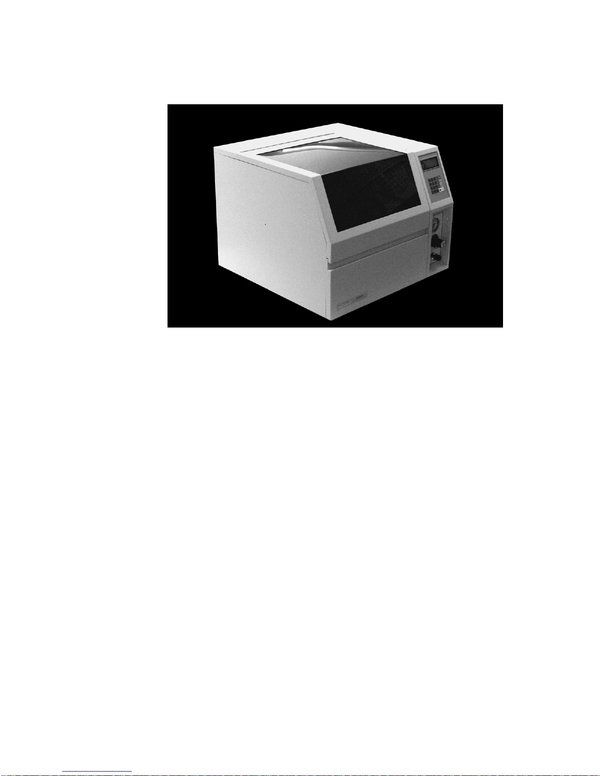
Product Description
The Archon Purge and Trap AutoSam pler is designed to automate the tedious
sample handling procedures associated with purge and trap analysis for volatile
organic compounds (VOC's) under current EPA methods. The Archon can be
used for drinking water, waste water, soil analysis, and solids. The Archon is
designed as a stand-alone unit for retrofit to purge and trap instruments.
The Archon is a state-of-the art robotic, X-Y-Z axis autosampler. The
AutoSampler utilizes a 51 position sam ple tray that allows water or soil samples
to be run. The tray can be cooled if an optional chiller kit is ins talled. The Archon
has a unique "gripper" arm which moves the sample vial to diff erent pos itions that
will bar code read (optional), identify the vial type, stir the sample, equilibrate to
room temperature, and transfer the sample to the water or soil probe position.
When running s oil samples, the Archon automates heated purge and trap. The
soil sample may be placed in the patented SoilVial, or if the Archon is s etup for
needle sparging, a standard 40 mL VOC vial. A stirring bar (optional) is added,
the cap with a low bleed septum is replaced, and the entire vial placed in the
sample tray. The robotic arm transfer s the vial to the vial identification step, and
then lifts the vial into the heated chamber where water is added, with one or both
standards, the sample is then purged directly onto the trap of the concentrator.
1 Introduction
If a water sample is to be run, the sample is placed in a 40 mL VOC vial and a stir
bar (optional) is placed in the vial and the vial is placed in the tray. The Ar chon
robotic arm moves the vial to the vial ID station and then to the pr obe location
where it is lifted onto the sample probe, and a program med volume of water is
transferred to the purge vessel. It is during the transfer that one or both of the
standards are added to the sample. It will also drain and c lean the needle, s parge
tube, and transfer lines.
The operating modes of the Archon are the Automatic, Manual, and Flush
modes. Automatic mode allows for complete unattended operation. Manual mode
operation allows for single sample operation of the unit, priority sampling, and
running blanks. The Flush m ode perform s the flushing with hot water and helium
for the cleanup of the system. All modes perform per their programmed method.
The Archon is easily programmed through its own color-coded keypad.
Programming is m enu driven and displayed on an LCD screen. Parameters can
be read and altered and the screen displays the function in progress during the
run.
The Archon interfaces directly with the Tekmar LSC 2000, 3000, OI 4460A, 4560
and other purge and trap units.
03-914642-00:6 1-1
Page 7

1.2
Design Features
Large 51 position removable sample tray for water or soil samples.
Runs blanks from its own blank/wash water reservoir.
Programmable sample dilution using blank H
directly from the 40 mL vial.
Water sample volumes programmable in 1-25 mL increments.
Programmable mechanical stirring of water samples containing sediment prior to
sampling.
All sample pathways are chemically inert, manufactured from PEEK®, Stainless Steel,
glass, or electroformed nickel.
Programmable dual standards allow for 1 or 2 different standards to be injected with the
sample, prior to purging.
Soil samples may be purged via needle sparge option utilizing disposable 40 mL vials or
by the patented SoilVial®.
The heated soil chamber can accept matrices consisting of solids, sludges, and liquids
from SoilVials or 40 mL EPA VOC vials.
Optional sample tray cooling capability. Optional refrigerated chiller is required.
O from reservoir, e.g., 0, 2, 5, 10, and 20,
2
Priority Sample feature allows the current analysis to be interrupted for RUSH samples.
Easily readable back lit LCD display.
Fast easy programming from the touchpad keyboard.
30 programmable methods may be stored for various method configurations.
A sample may be run from any position in the tray.
Easy hook up and installation to all purge and trap systems.
Back flushes the VOC soil probe pathway with line pressure helium.
Hot water rinse utilizes a cartridge heater to heat blank water to 90C prior to flushing
sample pathways and the purge vessel.
Intelligently determines if a temperature zone exceeds its set point.
Archon utilizes a 5-position temperature equilibrium chamber that ensures samples are
equilibrated at room temperature prior to sampling.
Positively identifies programmed SoilVials and water vials prior to placement into
sampling positions.
A heated upper soil valve to eliminate cold spots in the sample pathway of samples
purged in the soil chamber.
1-2
Page 8
1.3
Specifications
Introduction
Tray Capacity:
Sample Volume:
Flush Volume:
Indoor Use
Altitude:
Operating Temperature:
Relative Humidity:
Line Voltage:
Fuse:
Installation Category:
Pollution Degree:
Heat Dissipation:
Weight:
Size:
Gas Requirements:
51 sample vials. 40 mL EPA VOC or SoilVials
0-25 mL
0-25 mL
Up to 2000 m
15C to 35C; Storage Temperature 5C to 85C
10 to 90%
115 Vac 15%, 230 Vac 15%, 50/60 Hz 3 Hz
6A, 250 Vac, SB (115V); 3.15A, 250 Vac, T-Type (230V)
II
2
2500 BTU/Hr. Max. Worst Case
Approximately 80 lbs; 36.5 Kilograms
21.5W x 17H x 20D inches
54.6W x 43.2H x 53.3D centimeters
Helium 60-90 PSI 99.999% GC/MS grade purity
1.4
Component Description
The Archon consists of a base unit with a 51 position sample tray. The s ample
tray is removable from the front. A description of components follows.
1.4.1
Front Panel
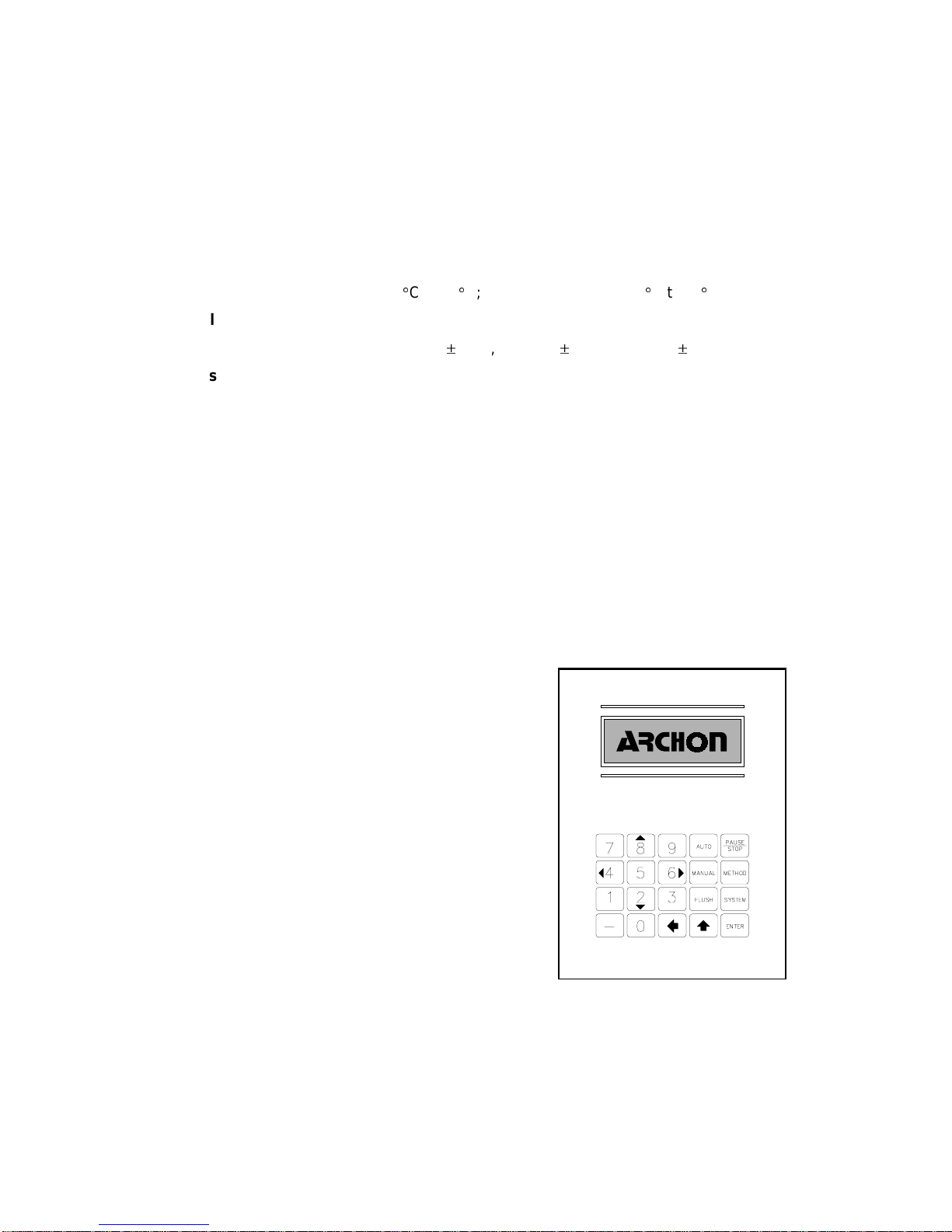
Keypad & Screen:
screen. The keypad allows for
entering or editing all information. The
LCD screen displays the information.
Keypad with LCD
Figure 1-1
03-914642-00:6
1-3
Page 9

1. Regulator: A regulator is provided for accurate
adjustment of the soil purge gas pressure and for
pressurizing the 40 mL vial during a water sample.
2. Pressure Gauge: A pressure gauge is located
above the regulator to monitor the purge gas and
to pressurize gas pressure.
3. Flow Controller: A flow controller is mounted on
the front panel to adjust the flow of purge gas
during the soil purge process.
4. Sample Tray Cover/ Door: The tray access cover
lifts up and locks to access the sample tray and
interior. The cover has a sensor mounted on the
right allowing the Archon to detect if the cover is
open. Additionally, there is a door at the bottom of
the Archon which allows the sample tray to be
removed / installed. Press the latch button and the
door will drop down.
1.4.2 Rear Panel
Power Module: The power access module has a detachable power cord and
contains the incoming line fuse, power selector and voltage selector card.
2
1
+
PURGE GAS
+
PRESSURE
_
PURGE GAS FLOW
3
Figure 1-2
Gas Input: A 1/8" Swagelok® bulkhead is used for He gas input ranged for 60-90
PSI.
Drain Line: The drain line is provided to attach to a waste bottle or a sink drain.
Remote I/O: All communication to the purge and trap and GC are m ade via the
25 pin, "D" connector. Custom built cables are des igned for each purge and trap
system to ensure correct handshaking.
Remote RS-232: A 9 pin, RS-232 "D" Connector will allow for operation via a
computer with a Windows® compatible program.
Water Connections: A water input connection is provided for supplying blank
runs, flush rinses and dilutions. A gas connection press ures the water reservior
to aid in water delivery and to ensure water cleanliness.
PAT Purge Cut Off Valve: T he Archon uses a valve to shut off the purge gas
supplied from the purge and trap concentrator during the soil purge. In this
mode, the Archon supplies the purge gas.
Sample Tray Coolant: The Archon will allow the sample tray to be cooled. An
optional recirculating bath (P/N DY-505627-00) must be purchased. Plumbing
connections for the bath are located on the lower, right rear side of the cabinet in
units shipped before March 1,1999. After that date, the plumbing kit
(DY-700085-90) must be purchased if a chiller option is installed. The liquid
coolant specifications are as follows: 10 PSI maximum pressure; temperature
range, -10 to 60C; Coolant liquid, 50/50% mix Ethylene Glycol / water, or 100%
water.
1-4
Page 10

1.4.3 Interior
Introduction
Refer to Figure 1-3.
Sample Tray (not shown): A 51 position, all aluminum, sam ple tray is provided
to hold sample vials. The tr ay is removable, and when installed, rests on top of
the aluminum tray cooler for cooling the samples.
1. Robotic Arm: The robotic arm is used to move the sample vials. A vial
gripper is used to remove the vials from the tray and place them in the
appropriate sampling positions.
2. Water Probe: The water probe is a patented concentric needle to puncture
water vials, pressurize, and displace water samples to the syringe. After
sampling, the probe is rinsed in a chamber that prevents sample from
spraying onto the instrument components.
3. Soil Probe: The patented soil probe and the Needle Sparge probes
incorporate a "T" fitting design for attachment of water and heated transfer
line. The probe is installed in a heated oven and easily removable for
cleaning or replacement.
4. 26 mL Syringe: A 26 mL syringe is used to move sam ple, blank, flush and
waste water. The syringe is mounted upright, directly into the valve manifold.
5
4
7
6
8
9
2
3
1
Figure 1-3
5. Standard Valve: The standar d injection station uses a 6 port valve with a 1
µL internal loop. The internal standard groove is filled by pressurizing the
standard reservoir and rotating the valve to positions 1 & 2, (Std. 1, Std.
2).Water samples or dilution water passes through the loop to deliver the
03-914642-00:6
1-5
Page 11

1.5
standard. Approximately 15 µL of standard solution is flushed during each
cycle.
6. Equilibrium Zone: The Archon utilizes a 5 position tem perature Equilibrium
station. If a sample has been cooled or heated, it can be cycled for an
equilibrium time in minutes, prior to analysis.
7. Vial Identification: The equilibrium station also contains the positive vial
identification sensor located in the first position from the left. This sensor
distinguishes between a SoilVial and a standard 40 mL water vial. The
second position contains the optional bar code reader used for sample
tracking.
8. Sample St ir Motor: The Archon allows the sam ple (both water and solid) to
be stirred. The motor is located below the vial sample stations. The motor
rotates a magnet which will spin a m agnetic spin bar placed in the vial. See
Section 7.11 for motor speed adjustment instructions.
9. Overflow Drip Pan: The Archon has a drip pan to collec t water in the event
of spillage. The pan has a fitting on the bottom to attach a 1/4" ID hose. Lift
the edge of the Archon and slide the 1/4" ID hose over the fitting. Route the
other end to a drain.
Vial Types
The Archon may use two different types of sample vials, depending on the
sampling type option installed. The two types of vials are shown below.
Patented SoilVial®
This vial is used if the Archon is pur chased with the
SoilVial Option installed. This double-ended vial
contains a frit at the bottom end and vial complies
with USEPA Method 5035.
use of the
on
both
ends.
bleed septum (P/N DY-504104-00)
low
This vial
requires
StanStandard 40 mL VOC vial
This is the standard USEPA approved glass vial. It
is used for water samples and for purging soil or
solid samples if the Archon is purchased with the
Needle Sparge option. When this vial is used for
purging a soil or solid sample, you
bleed septum (P/N DY-504104-00).
Vial types are NOT interchangeable. NEVER place a SoilVial in a
CAUTION
water vial location and NEVER use a SoilVial if the Archon is
configured with the Needle Sparge Option! Additionally,
permanent markers are recommended for labeling vials. If paper
labels are used, no more than two labels should be applied to
vials for reliable operation.
must
use a
the
low
Patented Standard
SoilVial 40 mL VOC
Figure 1-4
1-6
Page 12

Please read this section carefully before you begin to assemble the Archon.
2.1
Materials Needed
Regulator, single, two-stage with stainless steel diaphragm
In line on/off valve
Gas supply line tubing, minimum 1/8" diameter
Helium gas, 99.999% purity
Tools, 1/4", 1/16" open end wrenches; 3/16" blade screwdriver, Phillips screwdriver
Remote I/O Cable for communication to concentrator, see Section 8.
2.2
Unpacking the Archon
Each Archon is shipped in two cartons. The sample tray, accessory kit and
installation kit, with any optional spare parts, are shipped in a separate carton
from the Archon.
WARNING
Carefully open the shipping cartons. Lifting from the bottom remove the
Archon from its carton (the largest box). Place it on the bench to the left side
of the concentrator.
2 Site Preparation / Installation
Avoid back strain or injury by following all safety precautions
when lifting heavy objects.
Remove the sample tray, interface kit, interface cable, and any accessory or
spare items from the second carton.
Inspect for possible shipping damage or shortages. If damage is discovered,
immediately notify the carrier and Varian.
Varian Analytical Instruments
2700 Mitchell Drive
Walnut Creek, California 94598-1675
Attention: Manager of Customer Service
925-939-2400
Outside the U.S.A., notify the nearest Varian office.
Store the shipping cartons and all packing material for possible future use.
Inspect the contents against the packing list to determine if all items ordered
were received.
Locate the shipping, locking screw with spacer, on the left side of the cabinet.
This screw and spacer must be removed prior to turning the Archon on. Use a
small screwdriver to remove the screw. Save the screw and spacer for
possible future use.
03-914642-00:6
2-1
Page 13

CAUTION
If the Archon is to be shipped for any reason, the shipping screw
and spacer must be installed or serious damage will occur! See
Section 7.15
Before turning the instrument on: Check the eight blue reverse ferrule
fittings located in the sample area behind the rear panel (Section 11,
para. 11.2 and 11.4). Unscrew each fitting. Verify that the ferrule is
pushed over the tubing until the end of the tubing can be seen.
Replace and snugly tighten the nut.
Remove back panel. Locate the waste lines. Route lines through slot.
Parts and Materials Included in the Accessory Kit
2.3
The following items are included with the Archon Accessory Kit. Note: Remote I/O
cables are not included with the Archon, they must be purc hased separately. See
Section 10 for a list of cables and kits.
Operator's Manual
Blue aluminum nut
Tefzel® flange-free, ferrule, 1/16”
6 x 15 mm stir bars, pkg. of 6
1 ea. 80 oz. safety coated bottle
22 mm low-bleed septa, pkg. of 60
EPA 40 ml water vials and caps, pkg. of 12
51 position sample tray (note this is shipped in a separate box)
Composite warning labels
Water Transfer Line, SS, 1/16” x 5’ long
Stir bars (soil), pkg. of 6 (supplied with SoilVial® version only)
2 ea. SoilVial® (supplied with the SoilVial version only)
2 ea. Standard reservoir
(DY-505224-90)
Lab and Bench Space Requirements
2.4
The Archon requires bench space behind the instrument for the electrical and
helium gas connections. An additional 17” overhead clearance is required to allow
the cover to be opened.
From the rear of the Arc hon extend f lexible tubing (approx im ately 60”/1.5M) to be
connected to a blank water reservoir (80 oz./2L bottle) and to a user-supplied
waste receptacle(s). The waste receptacles must be located at or below the
height of the Archon base for proper drainage. Typically, both the blank water
reservoir and waste receptacle are placed on the floor behind the laboratory
bench.
2-2
Page 14
Site Preparation / Installation
The Archon dimensions are: 21.5W x 17H x 21D inches; 54.6W x 43.2H x 53.3D
centimeters (see Figure 2-1), and weighs approximately 80 lbs./36.5 kilograms.
17”H
21”D 21.5”W
2.5
Gas Connections
Figure 2-1
Ultra high purity helium (99.999% GC/MS grade) is required for purging soil
samples and operation of the vial gripper arm. The input supply pressure m ust be
60-90 PSI.
The helium gas line m ust be connected to the bulkhead fitting labeled “
.” Gas line must be 1/8” diam eter copper tubing and fittings mus t be 1/8"
Input
Swagelok®. Use a single, two-stage, high quality pressure regulator with a
stainless steel diaphragm. Consult your supplier for the proper type and size of
cylinder valves. An on-off, shut off valve, s hould be inst alled in the line to f ac ilitate
installation. Gas line tubing should be generous. Allow enough length, in a c oil, to
be able to move the Archon around to access the rear panel. Tighten and leak
test all connections using propanol and water.
Avoid any pipe thread connections in the supply line. If any fitting requires a
sealant, use an instrument-grade Teflon tape.
Helium
03-914642-00:6
2-3
Page 15

2.6
Electrical Connections
The Archon uses a grounded, three-pronged receptacle. Make certain the
electrical voltage is a constant source with no severe drops or spikes in the
voltage. If the power source is not certain, install a power conditioner on the
electrical line. Verify the correct fuse value and voltage selection for the line
voltage to be used.
Attach the power cord to the power receptacle on the rear panel. Check the
power switch located next to the receptacle to be certain it is OFF, plug the power
cord into a three-prong grounded outlet.
2.7
Electronic I/O Signal Connections
2.7.1 Purge and Trap Sync Cable Connector
The Archon comm unicates with the purge and trap concentrator and GC via a
cable specific to each m ake and m odel purge and trap and G C. Section 8 details
the Archon to purge and trap connections. The cable plugs into the 25-pin D
connector located on the rear of the Arc hon, labeled
of the cable attach to the purge and trap and the GC. See Section 8 for
installation instructions.
I/O signals vary; some GCs and purge and traps use normally-close contact
closures of active-high TTL logic; others us e normally-open contact closures or
active-low TTL logic. Refer to the operator's manual for each system for signal
information.
Remote IO
. The other ends
The Archon signal input configuration must be es tablished to properly receive the
purge and trap's output signals for Standby, Desorb and Stop. “
details the parameter configur ations for each of the signals. The factory default
setting for each signal is
CLOSED
2.7.2 Personal Computer Connection
The Remote RS-232 port on the Arc hon rear panel allows connection to external
computing devices. Specific software and cables are required for these
connections. Contact your sales representative for these products.
2.8
Water and Waste Lines Setup
2.8.1 Blank / Wash Bottle Setup
The Archon is supplied with an 80 oz. bottle and lines f or the blank, wash, and
dilution water. Remove the bottle from the accessory kit box. The clear line will
attach to the barbed fitting labeled “Helium” and the PEEK line will attach to the
fitting labeled “W ater.” See Figure 2-2, The Archon should be supplied with the
same high purity water (free of volatile organic c ompounds) that is used with the
purge and trap system. Rinse the bottle with purge and trap quality water then fill
it about 2/3 full with DI water. The bottle can be placed either on the bench top or
on the floor behind the Archon.
System Settings
.
”
2-4
Page 16

Figure 2-2
Site Preparation / Installation
Insert the cap, with the PEEK pickup line, into the bottle, screw the cap onto the
bottle.
NOTE: DO NOT OVERTIGHTEN THE CAP. SLOWLY TURN THE CAP
ONLY UNTIL SNUG. OVERTIGHTENING WILL SPILT THE CAP.
Verify the helium is turned on at the source. Turn the toggle valve for blank water
reservoir and standard helium to the ON position. The valve is located inside the
cabinet on the right rear wall, see Figure 2-3.
To test for a pressurized bottle, depress the vent button located on the blank
waste bottle plug. You should hear the release of pressure. T o refill the bottle,
turn the toggle switch OFF and vent the bottle by depressing the chrome button.
When the pressure is completely vented, remove the cap. Fill the bottle as
described above.
03-914642-00:6
2-5
Page 17

Toggle Switch
2.8.2 Waste Lines Setup
Cap
Figure 2-3
Chrome Vent
Button
2.9
Sample Tray Setup
WARNING:
SHOCK HAZARD
Remove the rear panel of the Archon and r oute the bundle of four plastic lines
through the slot in the chassis labeled “W aste Lines.” These waste lines should
empty into the user-supplied receptacles that are plac ed at a height equal to or
lower than the base of the Archon to provide proper drainage. Note that the
colored waste lines expel exces s standard solutions while the clear lines empty
waste water. The user may want to use separate waste containers f or the color ed
versus clear lines to allow different disposals.
Note: Instructions for two PEEK lines are found on page 2-12.
Remove the tray from its shipping carton. The tray is installed in the Archon
behind the lower door. Notice the tray has 51 positions and each location is
numbered. Raise the large tray cover and secure the arm loc k by gently pushing
it in the center and then lowering the cover. Press the latch button on the top
edge of the lower door and pull the door down.
Grasp the handles on the tray and insert the tray into the Archon with the number
1 position to the front left. The tr ay will rest on rollers as it is being inserted. Onc e
the tray is all the way in, it will “lock down” onto four posts. This will align the tray.
Dangerous voltages exposed when covers
are removed. Unplug power cord.
The tray must be pushed all the way to the rear most position in the
Note:
cabinet.
To remove the tray, lift the front of the tray, then slide the tray out the front on the
rollers.
The tray should be loaded by grouping the vials per the sample method chosen in
Section 5, e.g., water sample vials grouped together and soil sample vials
2-6
Page 18

grouped together. The method param eters, “First Vial - Las t Vial”, will determine
what vial numbers are run together.
The Archon vial gripper calibration coordinate settings m ust now be checked as
factory settings may have changed during shipping, therefore run the
“Calibration Test” procedure as described in Section 6.4.
Note: If any error messages appear while runing the Calibration Test, refer to
Drip Pan Drain
Site Preparation / Installation
Section 9-1. Refer to Section 6.4 for detailed calibration instructions.
Tray Posts
2.10
Sample Tray Coolant Setup (Optional)
The Archon sample tray can be cooled by an optional, refrigerated chiller bath
(P/N DY-505627-00), and plumbing kit (DY-700085-90) that c an be attached to
the coolant coil. It is located inside the cabinet under the tray. The tray rests on
top of the coil allowing conductive transfer of tem peratures. See Figure 2-4. The
coolant connections are located on the rear panel at the lower right cor ner and
are labeled “Tray Coolant, IN - OUT.” The tubing is 3/8" Duro. Refer to the
instructions included with the coolant and plumbing installation kit.
When the sam ple tray cooler is used, the drip pan drain MUST have a 1/4" ID
hose attached and be routed to a suitable drain. See Section 7.12 for cleaning the
drip pan.
2.11
Archon Soil Transfer Line Installation
This section will discus s the installation of the Archon sample transfer lines and
purge gas cut off solenoid valve lines to the purge and trap. This section will
explain the installation to the Tekmar 3000, 2000, and OI 4560.
Door Latch
Tray Rollers
Figure 2-4
03-914642-00:6
2-7
Page 19

Tools required are: 1/4", 2 ea. 5/16" open end wrenches, small flat blade
screwdriver, 9/64" and 3/32" Allen wrenches, and small needle nose pliers.
The installation of the Archon involves four primary steps. Note: All steps do not
apply to every purge and trap. Installation to each instrument is explained in detail
in later sections.
1. Installation of the four way “cross” fitting in the 2000 and 3000 valve oven.
2. Installation of the Archon heated soil transfer line.
3. Installation of the PEEK tubing for purge gas cut off.
4. Installation of the water transfer line.
The Archon installation kit c ontains various nuts, ferrules, and f ittings shipped in
the smaller carton with the Archon. Exam ine the c ontents of the carton to c onfirm
that all items are correct. Refer to Sections 2.1 through 2.3 for unpacking and
component details.
The installation of the Archon will require the use of two different types of nuts
and ferrules. See Figure 2-5.
28-694029-00
Valco nut with
one piece ferrule
2.11.1 Archon to Tekmar 3000
WARNING:
SHOCK HAZARD
The Tekm ar 3000 valve oven may be configured with one of two different
Note:
“tee” fittings. A 3-port on Serial Number units < 95073002 and a 4-port on units >
95073002. A 4-port cross fitting, P/N DY-505716-00 is supplied in the T ekmar
installation kit.
Replacing the 3-Port Fitting with the 4-Port Cross Fitting
in the Tekmar 3000 Valve Oven
1/8 “brass compression
nut with two piece ferrule.
28-694028-01
28-694027-01
Figure 2-5
Dangerous voltages exposed when covers
are removed. Unplug power cord.
Refer to Figure 2-6. The early Tekmar 3000 instruments (Serial numbers <
95073002) were shipped with 3-port fittings within the valve oven; c onsequently,
2-8
Page 20

Site Preparation / Installation
this does not allow the Archon to be installed. Therefore, the 3-por t f itting must be
replaced with a 4-port cross fitting.
1. Remove the top, left side and valve oven covers from the Tekmar 3000.
2. Using a screwdriver, loosen the screw which secures the thermocouple and
the clamp on the three-port fitting to the cabinet.
3. Using a 1/4" open end wrench, loosen the nuts in all three ports.
4. Loosen the two screws, which secure the sparge tube mount to the cabinet.
5. Pull the sparge tube mount and tubing, out of the 3- port fitting and off the
instrument.
6. Pull each of the other two lines out.
7. Replace the original fitting with the new 4-port cross fitting.
8. Attach all of the lines into the new fitting. Replace the sparge tube, with
mount, back on the cabinet.
Refer to Figure 2-6 for correct line placement in the new fitting.
03-914642-00:6
2-9
Page 21

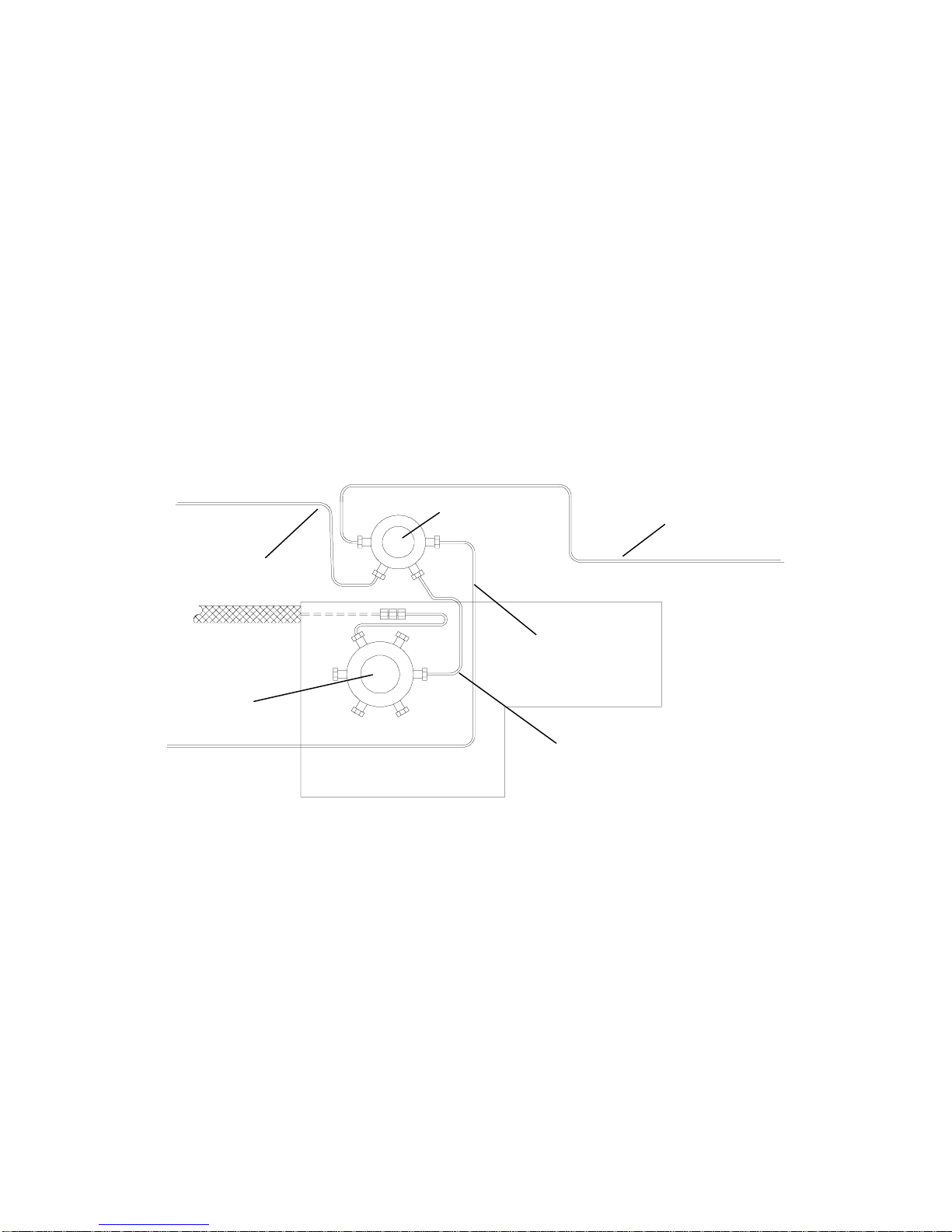
Archon Heated
Transfer Line
Assembly
DY-700001-01/02
Bolt with spacer
Transfer Line Sheath Clamp
with Standoff for GC
Transfer Line Only
GC Transfer
Line
Six Port Valve
Archon E-Form
Nickel transfer
Line
DY-505745-00
Figure 2-6
Four Port Cross Fitting
DY-505716-00
Oven
Thermocouple
Clamp
Sparge Tube Mount
Sparge Tube
2-10
Page 22

Site Preparation / Installation
Installation of the Heated Soil Transfer Line Assembly to the Purge and Trap
Refer to Figure 2-7 and Figure 2-8. Rem ove the accessory kit from the shipping
carton. Examine the contents and verify all items are correct. Remove the top, left
side and valve oven covers from the Tekmar 3000. Refer to the Tekm ar 3000
manual. Remove the rear panel from the Archon. Remove the Archon heated
transfer line and the water transfer line from the accessory kit.
1. Remove the plug in the Tekmar 3000 valve oven, 4-port cross fitting. This
fitting contains the lines to the six port valve, s parge tube and dry purge, the
fourth port contains the plug. Note: If your Tek mar 3000 does not have a 4port fitting see paragraph 2.11.1.
2. Insert the Archon transfer line assembly into the rear of the 3000. Fit the
Archon line assembly into the Tekmar 3000 transf er line channel. The Archon
line will rest on the top of the Tekmar 3000 GC transfer line.
3. Bend the end of the Archon nickel transf er line, so it will fit into the open port
on the 4-port cross fitting. Using a 1/4" open end wrenc h, tighten the nut. See
Figure 2-6. Be careful not to kink the line.
4. Push the two lines down into the channel.
Installation of the Heated Transfer Line to the Archon
1. Inside the Archon, use an Allen wrench to loosen the screw securing the
probe and upper soil valve cover. Rem ove the cover. Remove the ins ulation
block.
2. Insert the free end of the transfer line into the rear of the Archon, the line will
pass the open slot. Attach the transfer line bracket to the panel with the two
#4 socket head screws already installed in the rear panel.
3. Attach the transf er line to the upper soil valve using a 1/4" open end wrench.
See Figure 2-8.
4. Reinstall the insulation block and the probe cover and screw.
Note: On units =>12146, Heated Transfer Line is already installed on the
Archon.
03-914642-00:6
2-11
Page 23

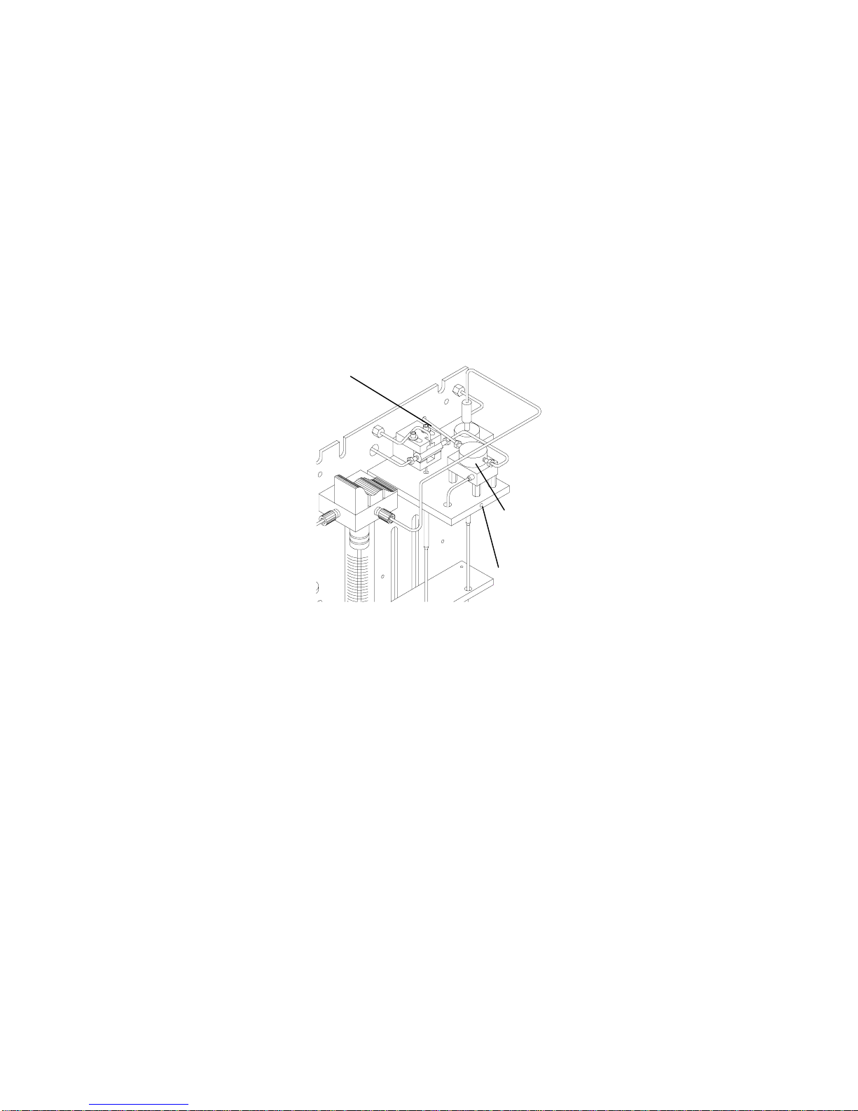
Archon Heated
Transfer Line
Heated
Transfer Line
Channel
Tekmar Heated
GC Transfer
Line Assembly
Figure 2-7
Assembly
Installation of Purge Gas Lines
Soil
Transfer
Line
Upper Soil
Valve
Cap Screw
(cover removed)
Figure 2-8
See Figure 2-9.
1. Remove the current purge
gas line from the “Purge”
fitting on the 3000 and the
sparge tube.
2. Connect the blue PEEK
tube to the “purge” out fitting
on the 3000. Use 1/16” nut
and ferrules for this
connection.
3. Connect the red PEEK tube
to the sparge tube fitting.
Use 1/16” nut and ferrules
for this connection.
4. Route the peek tubing lines
through the notch in the rear
panel of the Archon labeled
“waste lines”.
Water
Transfer
Line
Blue PEEK
Tube Connects
Here
Red PEEK
Tube Connects
Here
Sparge Tube
Fitting
Reverse
Ferrule
Fitting
Figure 2-9
½” SS
Nut
2-Way
Sample
Valve
Water Transfer Line Installation
The Archon transfers , cleans, and dilutes liquid sam ples to the sparge tube via a
five-foot stainless steel line and attaches to the 2-way valve on the top of the
sparge tube. Refer to Figure 2-9.
2-12
Page 24

1. Locate the nut and ferrule and the line from the accessory kit.
2. Uncoil the line. Locate the tan-colored PEEK valve body manifold inside the
right rear of the Archon. Slide the line into the fitting on the left. T ighten the
fitting by hand.
3. Route the line through the “notch” in the rear panel of the Archon labeled
“Waste Lines.” Route the line to the purge and trap.
4. The line will attach to the black 2-way valve on the top of the sparge tube.
5. T urn the handle so the valve is open toward the Ar chon trans fer line. Look in
the port to ensure the holes are aligned.
6. Slide the nut and reverse ferrule over the line and insert into the port on the
left side of the toggle valve. Tighten the nut.
7. Replace the rear door panel.
8. Remove sparge vessel. Make a slight bend about 3” (7.2 cm ) from end of
needle. (This maximizes the rinse ability of the Archon.)
Note: Make sure needle is not touching frit.
Tekmar 3000 Setup Specifications
After the Archon is installed, the T ekmar 3000 MUST be properly configured for
the I/O switch closures and method parameters to function correctly. This will
enable the Archon and the purge and trap to properly communicate.
Site Preparation / Installation
Use the hand held controller and press:
1. Conf
<A>= GC I/O port
B =Gas Flows
C =Installed Option
Select <A>
GC Port (standard/user) select “standard”*
GC Type=(63/31) Select “63”
GC Handshaking - (ON/OFF) Select “ON”*
Use the (-) key to toggle.
Press “Enter” after selection is made
*Note: Refer to cable hook-ups (pages 8-2 to 8-12).
2. Sched
A=Sample status
C=Commands
<E>=Edit Schedules
Select <E>
Start Stop Meth RPS
1) 0 0 14 1
2)
3)
03-914642-00:6
2-13
Page 25

To move cursor across page, Enter a “number” (0) and press Enter.
3. Meth
Method 14
Type Aquatek 50
Note: If Aquatek 50 is not selected the purge and trap will not send a
ready signal.
C=Command <E>=Edit
Enter the number 14 and press “Enter”. Select the “type” (63/31)
according to GC selection. Now, Select <E>.
Press “next page” until
Line Temp _____
Valve Temp _____
Then press “next page” until:
Sample fill - 0
Purge TIme 11.0
Then press “next page” until:
Sample Drain ON
Then press “next page” until:
BGB OFF Delay 0
4. Sched
A=Sample Status
<C>=Commands
E=Edit Schedule
Select <C>
<A>=Run Schedule
B=Update Schedule
C=Clear Schedule
Select <A>
This will load “New” method. To ver ify look in the upper right hand corner of the
key pad, “Display”, “M” and the new method selected should be displayed.
2.11.2 Archon to Tekmar 2000
WARNING:
SHOCK HAZARD
Remove the mounting hardware fr om the ac cessory kit shipping c arton. Exam ine
the contents and verify all items are correct.
To properly interface the Archon to the Tekmar 2000, a 4-way fitting must be
installed in the 2000 valve oven. Note the following installation procedures.
Verify that both the Archon and the Tekmar 2000 are turned
OFF and the power cords are disconnected before starting
the installation.
2-14
Page 26
Site Preparation / Installation
Installation of the 4-port Cross Fitting and the Heated Soil Transfer Line in the
Tekmar 2000 Valve Oven
Refer to Figure 2-10. Remove the trap c over, left side panel, right side panel, top
and the valve oven cover from the Tekmar 2000 as described in the Tekmar 2000
manual.
1. Using a 1/4" open end wrench, remove the three lines attached to the tee
inside the Tekmar 2000 valve oven. Remove the tee. Refer to the Tekmar
2000 plumbing diagram to confirm line locations.
2. Attach to the bottom right port of the new 4-way fitting, the short line attached
to the 6-port valve.
3. Attach the line from the sparge tube (previously removed from the Tekmar
2000 tee) to the upper left port on the new fitting.
4. Insert the Archon heated transfer line into the rear of the 2000, through the
hole labeled “ALS.” Attach the line to the bottom left port on the new fitting.
5. Attach the line from the “Dry Purge” valve (previously removed f rom the 2000
tee) to the top right port of the new fitting.
6. Check all fittings to ensure they are tight.
Transfer Line to
Archon
2000 6 Port
Valve
LSC 2000 Valve Oven
Figure 2-10
Installation of the Heated Soil Transfer Line
1. Inside the Archon, use an Allen wrench to loosen the screw securing the
probe and upper soil valve cover. Rem ove the cover. Remove the ins ulation
block.
2. Insert the free end of the transfer line into the rear of the Archon, the line will
pass the open slot. Attach the transfer line bracket to the panel with the two
#4 socket head screws already installed in the rear panel.
3. Attach the transf er line to the upper soil valve using a 1/4" open end wrench.
See Figure 2-12.
New 4 Port Tee
Sparge Tube Line
Line to Dry
Purge Valve
Line to 6 Port
Valve
4. Reinstall the insulation block and the probe cover and screw.
03-914642-00:6
2-15
Page 27

Hole
Soil
Transfer
Line
Bracket
Archon Heated
Transfer Line
GC Transfer Line
Figure 2-11
Installation of the Purge Gas Lines
Refer to Figure 2-13.
1. Remove the purge gas supply line at the fitting on the LSC 2000.
2. Connec t the blue PEEK tube to the purge gas supply fitting on the 2000. Use
1/16” nut and ferrules for this connection. Refer to Figure 2-13.
3. Connect the red PEEK tube to the sparge tube fitting. Use 1/16” nut and
ferrules for this connection. Refer to Figure 2-13.
4. Route the peek tubing lines thr ough the notch in the rear panel of the Archon
labeled “waste lines”.
Archon Water
Transfer Line
Upper Soil
Valve
Cap Screw
(cover removed)
Figure 2-12
2-way Sample Valve
Red PEEK Tube
Connects here
Sparge Tube Fitting
2-16
Blue PEEK Tube
Connects here
Purge Gas Supply Fitting
Figure 2-13
Page 28

Water Transfer Line Installation
The Archon transfers, cleans and dilutes liquid samples to the sparge tube via a
five-foot stainless steel line and attaches to the 2-way valve on the top of the
sparge tube. Refer to Figure 2-13.
1. Locate the nut and ferrule and the line from the accessory kit.
2. Uncoil the line. Locate the tan-colored PEEK valve body manifold inside the
right rear of the Archon. Slide the line into the fitting on the left. T ighten the
fitting by hand.
3. Route the line through the “notch” in the rear panel of the Archon labeled
“Waste Lines.” Route the line to the purge and trap.
4. The line will attach to the black 2-way valve on the top of the sparge tube.
5. T urn the handle so the valve is open toward the Ar chon trans fer line. Look in
the port to ensure the holes are aligned.
6. Slide the nut and reverse ferrule over the line and insert into the port on the
left side of the toggle valve. Tighten the nut.
Site Preparation / Installation
7. Replace the rear door panel.
8. Remove sparge vessel. Make a slight bend about 3” (7.5 cm ) of needle. ( T his
maximizes the rinse ability of the Archon.)
Tekmar 2000 Setup Specifications
After the Archon is installed, the Tekmar 2000 MUST be properly configured to
allow the I/O switch closures and method parameters to func tion correct ly. These
settings will cause the Archon and the purge and trap to properly communicate.
Confirm the following setpoint parameters have been established:
Set the bake gas bypass to: OFF.
Set the U012 DIP switch to: 3 open, other closed.
Turn the Autodrain: ON
Confirm the Desorb Time; be certain the Archon and
the purge and trap times match.
03-914642-00:6
2-17
Page 29

2.11.3 Archon to OI 4560
Remove the installation and accessory kits f rom the shipping carton. Examine the
contents and verify all items are correc t. The Archon m ay be positioned on either
the right or left side of the OI 4560.
WARNING:
SHOCK HAZARD
Remove the accessory kit from its shipping carton. Examine the contents and
verify all items are correct.
Be certain both the Archon and the OI 4560 are turned OFF
and the power cords are disconnected before starting the
installation!
Installation of the Heated Soil Transfer Line to the OI 4560
Refer to Figure 2-14.
1. Remove the plug installed in the AS port on the side of the OI 4560 spar ge
tube mount.
2. Slide the heated transf er line assembly through the two clamps. Attach the
clamps, with line, to the bracket us ing the #6-32 x 1/2" screws with nuts and
lock washers.
3. Slide the spec ial fitting (P/N DY-505727-00), provided in the Installation Kit,
onto the transfer line. Carefully bend the line and insert it, with the f itting, into
the AS port on the OI 4560. W ith a 5/16" wrench, tighten the larger nut first.
Push the line into the fitting and tighten the 1/4" nut.
4. Check all fittings and screws to ensure they are tight.
Installation of Purge Gas Lines
Refer to Figure 2-14.
1. Rem ove the OI 4560 purge gas line from the sparge tube and the outlet port
on the front of the 4560.
2. Connect the blue PEEK tube to the purge gas outlet on the OI 4560. Use
1/16” nut and ferrules for this connection.
3. Connect the red PEEK tube to the sparge tube fitting. Use 1/16” nut and
ferrules for this connection.
4. Route the peek tubing lines thr ough the notch in the rear panel of the Archon
labeled “waste lines.”
2-18
Page 30

Water transfer Line
Site Preparation / Installation
Heated Transfer
Line Assembly
From Archon
(red PEEK tube)
Purge Gas Outlet
(Blue PEEK tube connects here)
Compression Nut on
Sample Valve for
Water Transfer Line
Clamp
VOC
Transfer Line
Special 4560 Fitting
Sparge Tube
Fitting
Figure 2-14 Installation of soil transfer line to O.I. 4560
03-914642-00:6
2-19
Page 31
Installation of the Heated Transfer Line to the Archon
Refer to Figure 2-15.
1. Inside the Archon, use an Allen wrench to loosen the screw securing the
probe and upper soil valve cover. Rem ove the cover. Remove the ins ulation
block.
2. Insert the free end of the transfer line into the rear of the Archon, the line will
pass the open slot. Attach the transfer line bracket to the panel with the two
#4 socket head screws already installed in the rear panel.
3. Attach the transfer line to the upper soil valve using a 1/4" open end wrench.
4. Reinstall the insulation block and the probe cover and screw.
Soil Transfer
Line
Upper Soil
Valve
Figure 2-15
Cap Screw
(cover removed)
2-20
Page 32

Water Transfer Line Installation
Refer to Figure 2-16. The Archon transf ers, cleans and dilutes liquid samples to
the sparge tube via a five-foot stainless steel line and attaches to the 2-way valve
on the top of the sparge tube. Remove the rear panel of the Archon.
1. Locate the nut and ferrule and the line from the accessory kit.
2. Uncoil the line. Locate the tan-colored PEEK valve body manifold inside the
right rear of the Archon. Slide the line into the fitting on the left. T ighten the
fitting by hand.
3. Route the line through the “notch” in the rear panel of the Archon labeled
“Waste Lines.” Route the line to the purge and trap.
4. The line will attach to the black 2-way valve on the top of the sparge tube.
5. Rotate the two-way valve above the sparge tube so the ports are facing left
and front. The Luer fitting should be to the front. Remove the drain line. Us ing
a 5/16” wrench, install the modified Swagelok union with rubber washer to the
port on the left side. Route the line around the left side of the purge and trap
to the sample valve.
Site Preparation / Installation
6. T urn the handle so the valve is open toward the Ar chon trans fer line. Look in
the port to ensure the holes are aligned.
7. Slide the nut and reverse ferrule over the line and insert into the modified
Swagelok union. Tighten using two 5/16” wrenches.
8. Replace the rear door panel.
9. Remove sparge vessel. Make a slight bend about 3” (7.5 cm ) from end of
needle. (This maximizes the rinse ability of the Archon.)
Sample Valve Handle
Sample Valve
Modified Union
Water Transfer Line
Figure 2-16
03-914642-00:6
2-21
Page 33

OI 4560 Setup Specifications
These Parameter settings will ensure handshaking of the OI 4560 and the
Archon.
Note: The sample mount heater cartridge option should be installed to
minimize carryover.
1. From the keypad on the OI 4560, select: 2nd function - Configure and select
“STATES”, then press ENTER; Use the keys to select INPUTS or
OUTPUTS, then press ENTER.
2. Select INPUTS PRG - RDY or
Desorb RDY: If PRG - RDY is selected, set, Wait For Start, ON, then
ENTER; If Desorb RDY is selected, set, Wait For RDY, ON, then ENTER.
3. Press the “Clear” key.
4. Select OUTPUTS, then ENTER; Select Desorb - Output at Start ON
5. Press the “Clear” key.
6. Select Flows, then ENTER; Config. Desorb then Bake. First, Desorb -
Sample Drain ON, then ENTER, second, Config. Bake - Sample Purge ON,
then ENTER.
7. Press the “Clear” key to exit.
Soil Helium Purge Gas Flow Adjustment
2.12
Before running a soil sample the helium purge gas f low rate s hould be se t. T his is
accomplished by the helium purge gas flow controller (1), pressure adjustment
regulator (2), and gauge (3) located on the front right side of the Archon, see
Figure 2-17.
1. Adjust the purge gas regulator until the gauge
reads 20 -25 psi.
2. Load a clean vial with a new septum in the tray
and run a manual soil sample using this vial (see
Section 4.2).
3. Once the soil purge begins, check the f low rate at
the purge vent on the host purge and trap. Adjust
the helium purge gas flow controller on the Ar chon
to give the desired purge gas flow rate through the
purge and trap unit (typically 40 mL/min for m any
methods).
Note:All units are set to 40mL/min prior to
shipping.
+
PURGE GAS
PRESSURE
_
+
PURGE GAS FLOW
Figure 2-17
3
2
1
2-22
Page 34

2.13
Loop Calibration for Internal Standard
The absolute volume of the internal loop of the standard valve must be
determined to achieve accurate sample data. The stated 1 µL volume is
approximated within the stated tolerance from the valve manufacturer. For
absolute internal standard accuracy, use the following calibration procedure
before beginning your sample analysis.
1. Prepare a reference standard equivalent to a 1 µL volume injection via the
valve.
2. Run the calibration standard by hand (put 5 mL directly into the sparge tube.
Site Preparation / Installation
3. Run blanks in the Archon manual mode.
4. Calibrate the internal standard data by comparing the Archon data to the
2.14
Installation Checklist
Verify the following during and after installation of the Archon.
Be sure the manual mode
Note:
program calls for internal standard when running the blanks.
hand standard.
Be certain the sample tray is pushed all the way to the rear most
position in the cabinet.
Confirm the supply helium pressure is between 70-90 PSI 5 PSI.
Be certain the handle, on the black sample valve located on top of the
sparge vessel, is rotated in the position of the water transfer line.
Do not overtighten the cap on the blank/wash bottle. To properly
tighten the cap, turn it until snug, then stop.
Be certain the septum used for the soil samples is
P/N DY-504104-00. It is extremely important that this low bleed
septum is used because it is formulated for maximum sealing ability
with minimum bleed of siloxane compounds that might interfere with
chromatographic results.
This procedure will check all of the new fittings installed at the 4-way
03-914642-00:6
The caps, when used on SoilVials, must be tightened 1/4 turn past
finger tight to prevent leakage. A slight depression can be observed in
the septum when the cap is properly tightened.
Please review Sections 7.3 and 7.4, in this manual, “Cleaning the Soil
Transfer Line Frit and Replacement of the Water Line Screen.”
Perform system leak check on the purge and trap as specified in the
Tekmar LSC 2000, 3000, OI 4460 and OI 4560 manuals.
cross in the Tekmar 3000 & 2000 and at the external upper soil valve
supplied with the Archon.
2-23
Page 35

Lines attached to the upper soil valve must be installed with a Valco
stainless nut, P/N 28-694501-00 and a set of Swagelok stainless
ferrules, P/N 28-693996-00 and 28-693997-00.
Perform a soil purge leak check by checking and balancing flows at
the soil probe gas outlet bulkhead Swagelok fitting. Record flow rates.
Also, check flow at the vent fitting on the host purge and trap. (Flow
should be within 2 ml per minute.) Record flow rates.
Check vial calibration settings. The vial MUST move freely in and out
of the tray without resistance. Refer to Section 6.4.
Permanant marker pens are recommended to label sample vials.
Otherwise, no more than two labels should be applied to the vials.
MUST
The waste bottle or drain
be placed at a location which is equal
to or lower than the base of the Archon.
Make sure the sample needle in the sprage tube does not sit centered
or flush on the glass frit. The needle should touch the side of the
glass and sit slightly above the frit.
Review Sections 3, 4, 5, and 6.
Run a water method program (Section 5.4.1).
Run a soil method program (5.4.2).
Note: Use 7-10 mLs of clean H
0 for (Install Samples) on soil.
2
2-24
Page 36

3.1
General
3 Keypad Definition & Layout / Screen Display
The keypad provides a complete numeric pad as well
as a motion operation pad for the X -Y-Z axis arm. The
keypad is coupled with a 4 line, 20 character LCD
screen for displaying programming and status
information. The inf ormation will include the current vial
number, sample process sequence, temperatures,
remaining time in a run, Auto or Manual sample
indications, method parameters, warning indicators, and
general status information.
The keypad can be segmented into three key types:
See Section 4,
Figure 3-1
Operational, Setup, and Special.
Operation Keys, for a complete description of
operational key functions.
Numeric keys are used to enter numeric values 0-9 for
entering numeric information such as time or
temperature programming.
Operational Keys
Auto
Manual
Flush
Pause/Stop
Setup Keys
Method
System
Starts the autosampling procedure, see Section 4.1.
Starts a single sampling procedure or runs a Priority Sample,
see Section 4.2.
Performs the water/helium gas flush sequence of the sample
path, see Section 4.3.
Provides a pause in the current operation and/or a complete
abort of the current operation.
Selects a Method for editing and modifies the various Method
parameters.
Provides access to System Operation, Configuration,
Maintenance and System Diagnostics menus.
03-914642-00:6
3-1
Page 37

Special Keys
Enter
4, 6,
8, 2
—
Used to terminate the entry of a numeric or menu item selection.
It also serves as a scroll down key when selecting the Method
parameter setting.
Used to scroll up within the Method Parameter setting. Also used
to toggle the current motor selection and place the Archon in
“SYSTEM HOLD.”
Acts as a “backspace key.” Allows erasure of the current value of
any data entry item.
These keys have dual functions. They are numeric as well as
directional keys. These keys are used to scroll up or down for
menu selection and operation of motors in “System Calibration.”
This is an Escape Key. It can be used to exit a menu.
3-2
Page 38

4.1
Auto Key
The AUTO key starts the Archon autosampling sequence. When the AUTO key is
pressed the screen displays three lines:
The Method Number line will be in brackets (< >). Enter the correct Method
number using the numeric keypad, press ENTER. The BACKSPACE (
allows changing the Method number if nec essar y. Note: Pressing ENT ER without
changing the current Method Number will accept the default to the last Method
used. Pressing the UP
the method is selected, press ENTER. The 'START AUTORUN' will now be
bracketed, press ENTER, the AutoRun operation will now begin.
To start the Archon at a later tim e, use the 'DELAYED ST ART ' feature. Using the
"2" key, scroll down to the <DELAYED START> command line. Press ENT ER .
The screen will now display a menu line <Delay xx.xx hours>. Use the num eric
keypad to enter the amount of time delay before starting the AutoSampler
sequence. Note: The time entered will be in hours and hundredths of an hour.
Once the value is entered press ENT ER. The scr een will display time rem aining
before start, <Delayed Start xx.xx>.
4 Operation Keys
Keypad Display Entry Range
AutoSampler Start *
<Method Number: xx>
START AUTORUN
DELAYED START
(
) key, will backup the cursor to the previous line. Once
1-30
)
key
While the AutoRun is in progress, the Run-Time Screen will be displayed.
Keypad Display Entry Range
*Method xx * Auto
Vial = xx Soil (Water, Blank)
Vol = xx xx: 1 STD = 1 2
Current Status
* AutoSampler Start *
Exit
AUTORUN has been started, only the PAUSE / STOP key can be used to
interrupt the run. If a priority sample (additional sample to be run outside the
AutoRun sequence) is to be run, refer to Section 4.2
menu by pressing the AUTO key. However, once
Status only
(No user entries)
03-914642-00:6
4-1
Page 39
4.2
Manual / Priority Sample Key
The MANUAL key starts a single sam ple or Priority run. When the MANUAL key
is pressed the screen displays four entry selections:
Keypad Display Entry Range
*Manual Sample*
<Sample Vial #>
Method Number xx
Sample Type: Soil > (Water, Blank)
<START RUN>
The “Sample Vial#” (this is ignored if it is a BLANK) is now bracketed. Note, the
vial position number displayed is the last position entered. Using the numeric
keypad enter the correct vial position number. Press ENTER.
An incorrect vial type will cause severe damage to probes, needles
CAUTION
Using the numeric keypad enter the Method number containing the correct
Sample / Blank param eters, press ENTER. T he Sample Type will be updated to
the method’s sample type. If no change is made the method num ber defaults to
the last one used.
or vials. The sample vial location number entered contains the
correct vial type for the sample method to be run. If the “vial type”
is not turned on in Section 6.7, System Options, the Archon will not
identify a vial type automatically.
1-51
1-30
Soil, water blank
The “Sample Type: Soil” (W ater or Blank m ay be displayed depending on the last
sample type run). The sample type will be determined by the method selected.
The ‘”START RUN” is now brack eted, press ENTER. The MANUAL run will now
begin.
4.2.1 Running a Priority Sample During an AutoRun.
The Manual key is also used to interrupt an AutoRun to process a Priority
Sample. When the Manual key is pressed during the AutoRun, the screen will
display the following menu lines.
Keypad Display Entry Range
*Priority Sample*
<Sample Vial # = xx>
Method Number xx
Sample Type: Water, Soil
<PRIORITY RUN>
1. Enter the vial position number of the Priority Sample then press ENTER.
1-51
1-30
(Determined by method)
4-2
Page 40

Operation Keys
2. ENTER the Method Number for the type of sample to be run. Press ENTER.
3. Press ENTER again sc heduling the Priority Sample. A “P” will appear in the
upper left corner informing the user a Priority Sample has been scheduled.
The Priority Sample will begin after the current sample in progress is
completed, including any programmed blanks.
4. After c ompletion of the Priority Sample, the Pause Message will appear on
the screen.
Keypad Display Entry Range
4.3
System Paused
Enter to resume
Stop to reset
The Manual, Method, or Flush key may be pressed to perform additional
functions, or the ENTER key may be pressed to resume the AutoRun.
To cancel out of the Priority Sample menu, press the Manual key again.
Flush Key
The system is automatically flushed between samples. However, you may want to
manually flush the system if contamination or carryover occurs. The Flush Key
offers four options to decontaminate the water and soil sample pathways.
The FLUSH key displays the following menu. This key is only operational in
Manual mode. If an AutoRun is in operation the key will be ignored.
Keypad Display Entry Range
STATUS ONLY
(no user entries)
1. Drain the sparge tube
2. Flush the 26 ml syringe
3. Rinse the sparge tube
4. Backflush the water probe with helium
*Manual Flush*
<Drain Sparge Tube>
Flush Syringe
Rinse Sparge Tube
<Backflush W Probe>
Enter to resume
Stop to reset
Select the desired menu line by scrolling through the selections with the “ 2 “ or
“8 “ keys.
03-914642-00:6
4-3
Page 41

4.3.1 Drain Sparge Tube
The DRAIN SPARGE TUBE menu line will be highlighted with brackets (< >).
Press ENTER to initiate draining the sparge tube. A two-line menu appears:
Keypad Display Entry Range
* Drain Sparge Tube*
<Drain Volume: xx>
Drain Sparge Tube*
Enter a drain volume from 1-25 ml. Pres s ENTER. T he “Drain Sparge Tube” line
will now be in brackets. Press ENTER to start the drain.
4.3.2 Flush Syringe
To initiate the “Flush Syringe” sequence use the “2 ” Key to scroll down to the
“Flush Syringe” menu line. The command line will now be bracketed. Press
ENTER. The screen will display a menu with three selections:
Keypad Display Entry Range
*Flush Syringe*
<Flush #Times: xx>
Flush Volume: xx
Flush Syringe
1-25
1-20
1-25
Using the numeric keypad enter the desired num ber of flushes , from 1- 20. Press
ENTER, scrolling to the next menu line, “Flush Volume.”
Enter a value from 1-25 ml. Press ENTER key scrolling to the next menu line,
“Flush Syringe.” Press ENTER again to initiate the Flush Syringe sequence. Note,
this Flush sequence will only flush the 26 ml sample syringe.
4.3.3 Rinse Sparge Tube
The Manual Flush mode will also allow rinsing of the sparge tube and the 26 ml
syringe simultaneously. Use the “2” or “8” keys to scroll to the menu line
“Rinse Sparge Tube.” Press ENTER, the screen will display three menu lines.
Keypad Display Entry Range
*Rinse Sparge Tube*
<Rinse # Times: xx>
Rinse Volume: xx
Rinse Sparge Tube
1-20
1-25
4-4
Page 42

4.3.4 Backflush Water Probe
This function allows the water probe to be flushed with hot blank water and
helium. W ith the “2 ” or “8 “ keys scroll to the “<Backf lush W Probe>” menu
line, press ENTER. The flush process will begin immediately. The waste block will
be lifted then the probe flushed with hot blank water followed by helium. This
Backflush will occur each time the menu line is selected.
Keypad Display Entry Range
*Running* BACKFLUSH
Vial = NA Sam=NA
Vol=
Backflush W Probe
4.4
Pause / Stop Key
The “Pause / Stop” key is a multif unction key. Pressing the key once during an
AutoRun performs a PAUSE function.
Keypad Display Entry Range
System paused. Press
Enter to resume
Stop to reset
Operation Keys
4.5
System Hold
After the key is pressed the screen will display an “S” in the upper corner
indicating the Pause / Stop has been pressed. Onc e the sam ple run is c omplete
the “S” is removed, then the following message appears on the screen. The
Manual, Flush, Method and System keys are now functional.
Methods may be edited, Manual Sample may be perform ed, or any of the System
parameters can be changed. Press ENTER to resume the AutoRun from the
point it was paused.
Pressing the key twice will cause an abort /stop run, the Archon will then return to
a Standby state after going through the start-up sequence.
The Archon may be placed in a “HOLD” state by pressing . Once the key is
pressed, the Archon will HOLD the sequence it is cur rently running and display
“SYSTEM HOLD” on the bottom of the screen. Note, it does not effect the
robotic arm, standard motor, syringe motor or elevator motor. These movem ent
items must stop before the “SYSTEM HOLD” will tak e effect. To continue from
HOLD, press any key but the Pause/Stop key.
During SYSTEM HOLD, the timers will continue to run.
Note:
03-914642-00:6
4-5
Page 43

4-6
Page 44

5.1
Method Editing
The Archon allows 30 methods to be edited and saved into a battery backed
memory. To edit these parameters, press the Method key. The * Method * m enu
will be displayed. Enter the method number from 1-30, and press ENTER.
The menu line <EDIT METHOD> will now be bracketed. Press ENTER again.
The menu for editing parameters will now be displayed.
5.2
Sample Method Parameters
Pressing ENTER will cycle through each parameter to allow changes to be made.
Use the numeric keys to enter new values or the “2” and “8” and “4” “6”
keys as scroll keys. To scroll up in the menu use .
If an invalid entry is made, the system will change the value to be within the
allowable range.
5 Method Setup
Keyboard Display Entry Range
*Method* 1-30
<Method: XX>
EDIT METHOD
EDIT BLANK VIALS
To exit * Method Parameters * press the Method key again. Any changes will be
automatically saved.
Methods can be built for water, soil, or blank samples using the following
procedures. Although all parameters are listed below, only certain ones apply to
each method type. Recommended parameters for blank water and soil sample
are described in Section 5.4.
Parameter Range Default Description
Sample Type Soil, Water,
Blank
First Vial 1-51 01
Water
This selection will establish the type of
sample or blank to be run. A blank
method allows a series of blanks to be run
between other methods.
This is the first to be run using the
method. If
selected enter 1. (The First Vial, Last Vial,
parameter indicates the number of blanks
to be run. It does not indicate the vial
positions as in the water and soil
methods.)
BLANK
sample type is
03-914642-00:6
5-1
Page 45

Parameter Range Default Description
Last Vial 1-51 01
Sample Volume
Dilution
Factor
0-25 ml
0,2,5,10,
20,50,100
05
NO
This is the last vial or blank number to be
run. If BLANK sample type is selected,
enter the last number of blank to be run.
For example if you want two blank to be
run enter first vial=1 and last vial =2.
If the sample Type selected is Water or
Blank, this is the volume removed from
the sample vial or Blank/Wash bottle and
transferred to the sparge vessel. Note: If
the sample type selected is Soil, a
minimum of 3 ml of dilution water must be
selected in order for Standards to be
accurately added. The volume may be set
in 1 ml increments
The dilution factor shows the ratio of the
total volume of water sample and blank
water blended together to the volume of
24.3 mls., DF-NO is no dilution, DF-2 is 1
volume sample blended with 1 volume
blank water (50% dilution), DF-50 is 1
volume sample blended with 49 volumes
blank water (98% dilution). The “4” key
is used to change the dilution factor.
Rinse Volume 0-25 ml 05
#Rinses 0-20 01
Standard 1 YES/NO NO
Standard 2 YES/NO NO
S. PreHeat
YES/NO NO
Stir
Volume of rinse water used to flush the
PAT sparge tube during the bake mode.
The volume may be set in 1 ml
increments.
Number of times the sparge tube will be
flushed, using the rinse volume above,
during bake mode.
This parameter will enable or disable the
addition of 1 µl of standard #1 to the
Sample or Blank or into the Soil vial.
This parameter will enable or disable the
addition of 1 µl of standard #2 to the
Sample or Blank or into the Soil vial.
This parameter turns the stirring motor on
or off during the Soil PreHeat cycle. It can
be used to break up the solid sample.
Note: This is a soil only parameter.
5-2
Page 46

Parameter Range Default Description
Method Setup
Stir YES/NO NO
W. Stir Time
(min.)
W. Settle
0-9.9
0.0 min
minutes
0-99 seconds 00sec
Time (sec)
Syringe Flush 0 -20 YES
PreHeat YES / NO YES
PreHeat Temp
amb/140C40
This parameter turns the Soil mechanical
stirrer on during purge time, or the water
mechanical stirrer on for a sample mixing
prior to sampling.
The Stir motor will run for the length of
time entered for this parameter.
Note: This is a water method only
setting.
This time allows particulates in the
sample to settle back to the bottom of the
vial after the Stir process. This time is
used after stirring a Water sample.
This parameter allows hot water to be
flushed in the 26 mL syringe and out to
waste.
This parameter will allow the sample to
heat prior to purging. The heating will
occur after the water is added. Note: This
is a soil method only setting.
C
This parameter sets the temp for the
preheating of the sample. Note: This is a
soil method only setting.
PreHeat Time 0-99.9 min. 3-0 min.
Purge Time
(min.)
Desorb Time
(min)
0-999.9
minutes
0-99.9
minutes
11.0 min
2.0 min
This parameter sets the time for
preheating of the sample. Note: This is a
soil method only setting.
This is the time the sample will be purged.
This parameter must match the time
programmed on the purge and trap
concentrator. Note: This is a soil
method only setting.
This parameter must match the time
programmed on the purge and trap
concentrator. The purge vessel is auto
drained back to the Archon waste bottle
during desorb.
03-914642-00:6
5-3
Page 47

Parameter Range Default Description
Operate Mode Local /
Remote
Remote
Cycle Timer 0-99.9 min. 00.0 min.
This Mode determines if the Archon will
depend on switch signals from the purge
and trap to advance, or be dependent on
the Cycle Timer. In the “Local” Mode,
the Archon will start when the Cycle
Timer parameter, set in the method has
elapsed. NOTE: In Local, the Ar chon will
NOT respond to switch signals from the
purge and trap, i.e. Standby (Ready) and
Desorb Ready. In the “Remote” Mode,
the Archon responds to the switch signals
given by the purge and trap and the Cycle
Timer parameter. Once the purge and
trap reaches its Standby mode, a signal
output will start the Archon, provided the
Cycle Timer has reached 0.0.
This will advance the Archon from a ready
to sample mode. T he Archon starts when
a purge ready signal is received from the
purge and trap, in the standby mode. The
cycle includes the purge time, plus the
GC run time and cool down. The cycle
time is normally used to ensure that the
GC will be ready to receive the next
sample. In the case of short GC run
times, cycle time will not be effec tive, and
should be set to "0.”
Auxiliary
Timer
Link to
Method
0-99.9 min. 00-0 min.
0-30 0-00
This is a timed event output used to start
or stop additional external equipment.
The timer starts af ter the s ample goes out
the sparge tube for a water or a blank
sample or at the start of the purge for a
soil sample.
The Archon will continue the sampling
sequence for this method upon
completion of the current selected
method. Any combination of methods
may be linked together providing for
continuous operation. Note: Circular
linkage of a method is allowed, i.e.,
linking a method to itself to continually
cycle through one method. Set the
parameter to "0" to stop the autosampler
after the last vial in the method.
5-4
Page 48

5.3
Blanks After Vial Editing
Single blank runs can be programmed after specific sample vials within a
particular method. These are known as "Method Blanks" and complement the
alternative of creating a whole method where all of the runs are blanks.
Method blanks are particularly useful when analyzing sample sets containing both
high and low concentration samples. T he blank s allow additional s ystem cleaning
of not only the Archon, but also of the Purge and Trap and the GC. T he blank
water is withdrawn from the blank water reservoir rather than a user-prepared
vial, but otherwise is followed by the whole analysis sequence. Method blanks can
also be used to confirm that cross-sample contamination has not occurred.
To program Method Blanks, build the rest of the method first entering the
parameters under the <Edit Method> m enu. Then press the "Method" k ey to exit
to the *METHOD* menu. Scroll down to <Edit Blank Vials> and press Enter.
The *Method Blanks* menu, as shown, will allow the programming of a single
blank water run after any of the sample vials in the method. Note that the vial
numbers for which a following blank may be programmed are restricted to the
range defined by the <First Vial> and <Last Vial> entries in the earlier method
parameters.
Method Setup
*METHOD#BLANKS*
<Vial#= Blanks= YES (NO)>
U/D changes vial.
L/R changes blank.
The U/D menu line allows for changing the vial number after which the blank will
be run. Use the “2” and “8” keys to change the vial number. The L/R menu
line allows for selecting ‘YES’ or ‘NO’ to correspond with the vial number. Use the
“4 ” and “6” keys to change the response.
To speed the entry of information from the * Method Blank s * menu, press the
number “1” to set the First Vial, Last Vial range positions to Blank ‘YES’, or press
“0” to set the vial position range to ‘NO’.
To exit out of the
the
* Method *
menu, press the Method key again.
* Methods Blanks *
menu press the Method key, to exit out of
03-914642-00:6
5-5
Page 49

5.4
Method Programming Guidelines
5.4.1 Water Met hod Program
To aid you in programming, please review the following
example of a typical
start with these settings and if necessary, make
adjustments after running several standards and or
samples. In this example, Method “1” will be
programmed for
If a recirculating bath is installed for cooling the
Note:
sample vials, the Equilibrium Count and Time should be
used. Sections 5.5 and 6.4.5 describe the use and
programming of the Equilibrium station.
Water
Water
sample You may want to
, method “2” for
Soil
.
5.4.2 Soil Method Program
The following is an example of a typical soil method that
can aid building your method. You may start with these
settings then make adjustments as necessary after
running several standards and or samples. In this
example Method 2 will be programmed for
If a recirculating bath is installed for cooling the
Note:
sample vials, the Equilibrium Count and Time should be
used. Sections 5.4 and 6.7 describe the use and
programming of the Equilibrium station.
Note: There must be 10-15 mLs total volume of liquid in a
soil sample prior to purging.
Soil
.
*Method 1*
Sample Type:
First Vial:
Last Vial:
Sample Volume;
Dilution Factor
Rinse Volume
Rinses
Standard 1
Standard 2
Stir
W Stir Time (min,)
W Settle Time (sec.)
Syringe Flushes
Desorb Time (min.)
Operate Mode
Cycle Timer
Aux. Timer
Link to Method
*Method 2*
Sample Type:
First Vial:
Last Vial:
Sample Volume
(see note)
Rinse Volume
Rinses
Standard 1
Standard 2
S PreHeat Stir
Stir
Syringe Flushes
PreHeat
PreHeat Temp
PreHeat Time
Purge Time (min.)
Desorb Time (min.)
Operate Mode
Cycle Timer
Aux. Timer
Link to Method
Water
1
5
5 ml
0
5ml
2
YES
NO
NO
0
0
1
4 MIN.
Remote
65 min.
0
2
Soil
6
10
5 ml
0
0
YES
NO
NO
YES
0
YES
40
3
11
4
Remote
65 min.
0
3
5-6
Page 50

5.4.3 Blank Method Program
If Blank is selected as the Sample T ype in the Method
Edit Screen, the parameters entered will be the sam e as
for a Water sample, except those requiring vial
movement. However, the First Vial, Last Vial parameter
entries are not actual vial positions. Instead they are
used to enter the number of Blank runs to perform.
Example: First Vial is set at #1, and Last Vial at #5.
There will be 5 blank runs with these settings.
5.5
Equilibrium Count and Equilibrium Time
The Equilibrium Count and the Equilibrium Time parameters allow samples
cooled with the optional tray-cooling system to be equilibrated to warmer
temperatures before analysis. Because tray cooling affects all samples
regardless of method, the Equilibrium Tim e par am eters ar e actually set within the
“system settings” menus, (see Section 6.6). They are discussed here for
continuity. The Equilibrium Count is the number of vials (5 is the max imum ) to be
placed in the Equilibrium zone station for temperature equilibrating, see Figure
5.1. Initially, the vials are loaded in the zone starting with the left, vial identification
section, each remaining cup to the right will then be filled. The vials will be loaded
left to right until the “Equilibrium Count” is reached then transported to the
sampling station. The remaining vials will be moved from right to left, ending in
the vial identification cup, the empty cup on the right will be loaded with a new
vial.
*Method 3*
Sample Type:
First Vial:
Last Vial:
Sample Volume
Standard 1
Standard 2
Flush Syringe
Desorb Time (min.)
Operate Mode
Cycle Timer
Aux. Timer
Link to Method
Method Setup
Blank
1
5
5
YES
NO
1
4
Remote
65
0
0
The Equilibrium Tim e programm ed is the minimum time each vial will rem ain in
the Equilibrium section to reach ambient temperature. Refer to Section 6.6
“System Settings” for details on the default settings for the Equilibrium Count and
Time.
Equilibrium Zone Station
1. Vial Identification cup, #1
3
2
1
2. Bar Code Identification cup
(Optional)
3. Position #5
4. Soil Sampling Location
5. Water Sampling Location
5
4
Figure 5-1
03-914642-00:6
5-7
Page 51

5.6
Operating Sequence Steps
This section describes the Archon operational sequence steps during a typical
sample run. As an aid to the operator, the sequenc e steps are displayed on the
LCD screen while the Archon is running.
5.6.1 Water Sampl e Sequence
Sequence Step Purpose
1. Getting Vial The Robotic Arm picks up the sample vial.
2. Check Vial Type The vial is placed in the ID cup to identify its type.
3. Going to water probe The vial is transported to the water sampling station.
4. Parking The Robotic Arm goes to rear park.
5. Stirring Water sample is stirred.
6. Settling Allows particulates to settle.
7. Elevator up The sample vial is raised onto the water probe.
8. ml for backflush
9. (No) sample dilution Programmed dilutions are performed.
10. ml for backflush
11. Helium ->waste Helium flushes sample path to waste bottle.
12. Water ->waste Water flushes sample path to waste bottle.
13. Helium ->waste Helium again flushes sample path to waste bottle.
14. Adding standard 1
(and/or 2)
15. Sample -> sparge tube The sample is pressurized into the syringe then
16. Elevator down The vial is now lowered from the water probe.
17. Flush syringe If syringe flushes have been programmed.
18. Heating water Water is heated.
19. Water -> lines Hot water fills the lines.
20. Water-> syringe Hot water fills the syringe.
Standard 1 and/or 2 is added to the sample.
transferred to the sparge tube.
5-8
Page 52

Method Setup
Sequence Step Purpose
21. Syringe -> waste The syringe now transfers the water to the waste bottle.
22. Helium ->waste Helium is flushed through the sample path to the waste
bottle.
23. Flush complete. Syringe flushing is complete.
24. Return vial The Robotic Arm verifies the vial position is empty, then
picks up the vial and returns it to the sample tray.
25. Parking The Robotic Arm goes to rear park.
26. Backflush water probe The water probe will now be flushed with hot water.
27. Elevator up The elevator raises the sampling stations.
28. Heating water Water is heated.
29. Water->water probe The backflush with hot water now begins.
30. Helium ->water probe After the water backflush is complete the probe is now
flushed with helium.
31. Elevator down The elevator moves down.
32. Autodrain The Archon waste valve opens and helium pressure
from the purge and trap will now drain the sparge tube.
33. Drain sparge tube The Archon will initiate a safety drain.
34. Sparge tube -> syringe If any sample water remains in the sparge tube, it is
drawn into the syringe.
35. Syringe -> waste The syringe transfers the water to the waste bottle.
36. Rinse sparge tube The sparge tube is rinsed if rinses have been
programmed.
37. Heating water Water is heated.
38. Water -> lines Hot water fills the lines.
39. Water -> syringe Hot water fills the syringe.
40. Syringe -> sparge tube The syringe transfers the water to the sparge tube.
41. Sparge tube -> syringe The syringe withdraws the water from the sparge tube.
42. Syringe -> waste The syringe transfers the water to the waste bottle.
03-914642-00:6
5-9
Page 53

Sequence Step Purpose
43. Helium -> waste Helium is again flushed through the sample path to the
44. End liquid sample This completes the water sample process sequence.
5.6.2 Soil Sample Sequence
Sequence Step Purpose
1. Getting Vial The Robotic Arm picks up the sample vial.
2. Check Vial Type The vial is placed in the ID cup to identify its type.
3. Going to soil probe The vial is transported to the soil sampling station.
4. Parking The Robotic Arm goes to rear park.
5. Water-> Lines Water flushes internal standard path to the waste
6. Elevator up The sample vial is now raised up onto the soil
waste bottle.
bottle.
probe.
7. Syringe fills Syringe fills with programmed amount of water.
8. Adding standard 1 (and or 2) Standard 1 and or 2 is added to the sample.
9. Water -> soil vial Water is transformed to the soil vial.
10. Helium ->waste Helium flushes sample path to the waste bottle.
11. Pre-heat Soil Sample Sample vial is heated.
12. Pre-heat Time Length of time of heating.
13. Purge Sample is purged.
14. Elevator down The vial is lowered from the soil probe.
15. Return vial The Robotic Arm verifies vial position is empty, then
picks up the vial and returns it to the sample tray.
16. Parking The Robotic Arm goes to the Rear Park
17. Autodrain The Archon waste valve opens and helium
pressure from the purge and trap will drain the
sparge tube.
5-10
Page 54

Method Setup
Sequence Step Purpose
18. Helium -> waste Helium is now flushed through the sample path to
the waste bottle.
19. Rinse sparge tube The sparge tube is rinsed if rinses have been
programmed.
20. Heating water Water is heated.
21. Water -> lines Hot water fills the lines.
22. Water -> syringe Water fills the syringe.
23. Syringe -> sparge tube The syringe transfers the water to the sparge tube.
24. Sparge tube -> syringe The syringe withdraws the water from the sparge
tube.
25. Syringe -> waste The syringe transfers the water to the waste bottle.
26. Helium -> waste Helium is again flushed through the sample path to
the waste bottle.
27. End soil sample This completes the soil sample process sequence.
5.6.3 Blank Sample Sequence
Sequence Step Purpose
1. Water -> lines Water flushes internal standard path to the waste
2. Water -> syringe Water is now transferred to the syringe.
3. Helium -> lines Helium flushes sample path to the waste bottle.
4. Adding standard 1 (and/or 2) Standard 1 and/or 2 is added to the sample.
5. Sample -> sparge tube The blank sample is pressurized into the syringe then
6. Autodrain The Archon waste valve opens and helium pressure
7. Drain sparge tube The Archon will initiate a safety drain.
bottle.
transferred to the sparge tube.
from the purge and trap will drain the sparge tube.
8. Sparge tube -> syringe If any sample water remains in the sparge tube, it is
03-914642-00:6
drawn into the syringe.
5-11
Page 55

Sequence Step Purpose
9. Syringe -> waste The syringe transfers the water to the waste bottle.
10. Rinse sparge tube The sparge tube is rinsed if rinses have been
programmed.
11. Heating water Water is heated.
12. Water -> lines Hot water fills the lines.
13. Water -> syringe Hot water fills the syringe.
14. Syringe -> sparge tube The syringe transfers the water to the sparge tube.
15. Sparge tube -> syringe The syringe withdraws the water from the sparge
tube.
16. Syringe -> waste The syringe transfers the water to the waste bottle.
17. Sparge tube ->syringe If any sample remains in sparge tube, it is drawn into
syringe.
18. Syringe -> waste The syringe transfers sample to the waste bottle.
19. Helium ->waste Helium is again flushed through the sample path to
the waste bottle.
20. Flush syringe If flushes have been programmed.
21. Heating water Water is heated.
22. Water -> lines Hot water now fills the lines.
23. Water -> syringe Hot water now fills the syringe.
24. Syringe -> waste The syringe now transfers the water to the waste
bottle.
25. Helium -> waste Helium is again flushed through the sample path to
the waste bottle.
26. Flush complete Syringe flushing is completed.
27. End water blank This completes the blank sample process sequence.
5-12
Page 56

6.1
The “System” Key provides a menu to access all Settings, Maintenance,
Calibration, and Options of the Archon. Pres sing the “System ” k ey will display the
following menu.
Front Park
This setup procedure will move the Robotic Arm to the front left corner of the
instrument allowing easy access to the rear of the Archon for service or
maintenance.
*System Setup *
<Front Park>
Status
Maintenance
Calibration
Diagnostics
Settings
Options
CAUTION
6 System Setup
Contact Varian before making any calibration
and setting changes.
6.2
System Status
Using the “2” or “8 ” keys, select the “Front Park” menu line, pres s ENTER.
The display will now show:
Press any key to
rear park gripper
Press any key to begin moving the Robotic Arm. T he *System Setup* menu will
be displayed during the movement. Once stopped, the
displayed.
Press any key to front
park gripper
After the service or m aintenance is complete, pres s any key to move the gripper
back to the rear.
This menu will display the time remaining for the Cycle Timer and provide a
status for heated zones:
*System Status*
<Cycle Timer xxx.xmin.>
Soil Tran Line
Set xx Actual=xx
rear park
screen will be
03-914642-00:6
6-1
Page 57

6.3
Maintenance
The “2” or “8 ” keys will scroll through the temperature zones. They are:
Zone Default Set Point
Soil Sample Chamber OFF
Equilibrium Block OFF
Upper Soil Probe 110°C
Soil Transfer Line 110°C
Upper Soil Valve 95°C
Ambient OFF
Tray Temp OFF
The SET point and Actual (current) tem peratures are displayed. If the heater is
not active, the SET point will show “OFF.” If the “Actual” temperature displays
“???”, this indicates a thermocouple is open. Contact a Varian service
representative before proceeding.
This menu allows the internal standard reservoirs to be filled and the lines prim ed
with standard. This menu also allows the user to reset movement counters.
* System Maintenance *
<Standard Control>
Adjust Counters
Shipping position
Clean Syringe
Elevator up/down test
6.3.1 Standard Control
Select, from the main menu, <Standar d Control>, press ENTER. The *Standard
Control* menu will be displayed. Select the <Front Park> command. Press
ENTER. The Robotic Arm will now move to the front left corner.
Select “Prime Std. 1 or 2.” Press ENTER. T his will cause the motor to rotate in
the direction of the Standard selected. Standard 1 is on the lef t and Standard 2 is
on the right. The valve will stop when it recycles the load position and allow the
standard solution to prime the lines, then it will return to the sample position.
* Standard Control *
<Front Park!>
Prime Std 1 Loop
Prime Std 2 Loop
6-2
Page 58
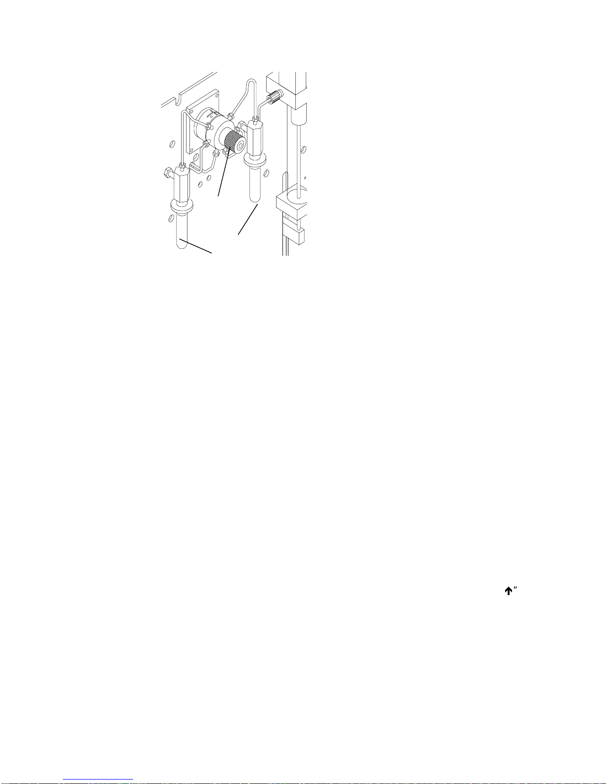
System Setup
Standard
Valve
5 mL
Vials
Figure 6-1
After the lines have been primed, select the menu line <Rear Park>. Press
ENTER, the arm will now move to the rear of the cabinet.
Note: See Section 7 for standard vial installation instructions.
6.3.2 Adjust Counters
The Archon maintains a movement count of critic al com ponents that c an be used
to schedule routine maintenance.
They are: Vial count, this is a continuous count of sample vials run.
Select the *Adjust Counters* menu line, pr ess ENTER. The Counter” menu will
be displayed.
The numeric key pad is used to change the count data. The ENTER and “UP”
key will scroll through the menu lines.
6.3.3 Shipping Position
* Counter Adjust *
<Vial xxxxx>
Plunger xxxxx
Waste Block xxxxx
Syringe Plunger, this is a movement count of the 26 ml syringe
plunger each time it reaches its “home” (up) position.
Waste Block, this is a count of the movement of the water probe
into the Waste Block. During the clean up cycle, the tip of the
water probe is covered and the entire probe is flushed with water
and helium.
Selecting this prompt will move the XYZ mechanism and syringe elevator to a
secure position. Remove the sample tray, install the shipping sc rew and spacer
on the left side of the unit, disconnect the gases, and remove power from the unit.
03-914642-00:6
6-3
Page 59

6.3.4 Clean Syringe
This prompt will m ove the XYZ mechanism to the fr ont of the unit to allow c lear
access to the syringe. The display will prompt you for each step of the syringe
cleaning. Refer to Section 7.13 “Cleaning or Replacing the Syringe Plunger ORing” for a description of the procedure.
6.3.5 Elevator up/down
This prompt will exer cise the sam ple elevator up and down. Press “Enter” ke y to
stop operation.
6.4
System Calibration
This menu allows the selection of r outines for calibrating target positions for the
Robotic Arm and Gripper. The "Calibration Test" and "Auto Calibrate" are
automated routines that check and adjust a num ber of positions. The remaining
menu items allow manual positioning and calibration for specific instrument
operations.
[keypad display]
*Calibration Setup*
Auto Calibrate
Calibration Test
Vial 22 Position
Water Probe Vial Position
Equilibrium block
Knockoff Clearance
Standard Clearance
Once a calibration step is initiated, all of the above steps must be
Note:
performed to assure the unit is properly aligned.
The "Calibration Test" and "Auto Calibrate" routines allow automated testing and
readjustment of m ost of the robotic arm calibration settings . These routines are
used to quickly verify the operational status of the robotic arm and to make
adjustments to compensate for normal wear.
6.4.1 Calibration Test
To run
The
the
This test will verify if the current s ettings are s till appropriate. Us e the "8" or the
"2 " key to scroll to the "Calibration Test" menu line and press ENTER.
Following the displayed instructions, remove all but vial #1 and press ENTER
again. The test will begin.
Observe the gripper as it lowers over the vial. It should clear the vial with no
jamming and hesitations. If an ERROR code appears or the gripper movement
looks abnormal, refer to Section 9.
“Calibration Test”
*SYSTEM SET UP*
“Calibration”
program, press the
menu will be displayed. Using the “2” or “8” k ey scroll to
menu line and press ENTER.
“SYSTEM”
key, from the key pad.
6-4
Page 60

Note: If calibration test fails go to Section 6.4.2.
Note: Before beginning refer to the Default Operation Value Table on page 6-15.
6.4.2 Auto Calibrate
The "Auto Calibrate" program allows the Archon to automatically establish the
correct coordinate position s ettings for removal and r eplacement of sample vials
in the sample tray, water vial sampling station, soil/solid s am pling station, and the
equilibrium ID station. These settings are essential for accurate vial / gripper
movement. After the Archon has been installed to the pur ge and trap, and
running the first sample
should also be run after ANY service to the vial gripper assembly or if ANY
gripper movement error message has been displayed. Also, if the Archon has
been relocated for some reason, run the "Calibration Test " program.
Note: Once Auto Calibrate is initiated, all other calibration steps must be
performed to assure the unit is properly aligned.
Locate the Calibration Bar (P/N DY-505894-00) and Calibration Pin (P/N DY505893-00) shipped with your instrument.
System Setup
before
, run the "Calibration Test" program. The program
Note: To order a replacement Calibration Bar and Calibration Pin, order Kit
Number DY-505419-90.
To run the "Auto Calibrate" program, press the "System” key, from the key
pad. The *System Setup* menu will be displayed. Using the “2” or “8” key scr oll
to the "Calibration" menu line and press ENT ER. Scroll up one position using
the “8” key to the “Auto Calibrate" menu line. Press ENTER. The following
menu is displayed:
Insert Bar in Tray
10 and 17. Press
Enter when ready or
- to Abort.
Insert the Calibration Bar into the sample tray in positions 10 and 17.
Press ENTER.
The following message will appear:
Insert Bar Sensor in Gripper.
Press any key to
Continue.
Slide the bar sensor device up into the vial gripper. Note: The end with the silver
rod protruding through the device goes DOWN. Press any key to begin the
calibrate program. The vial gripper will now move to the Calibration Bar in the
sample tray, then to the water vial sampling station, equilibrium ID station and
then the soil / solid sampling station.
After completion of the program, the following message will appear:
03-914642-00:6
Remove Bar Sensor in Gripper.
Press Any key to Continue.
6-5
Page 61

Remove the sensor device fr om the vial gripper . (Gently pull it down until it slides
out.) Press any key to park the vial gripper.
CAUTION
If you fail to insert the sensor device into the vial gripper, the Archon will still
attempt to run the program, however, it will not be able to detect the sensor bar
and the following message will appear:
Calibration Failed.
Press Enter to Retry
- to exit.
Press ENTER and then insert the sensor device and run the program again.
Once the
Scroll down using the #2 key to <vial 22 position) and c alibr ate the ver tic al height.
Press the 7 key for Train. Press “7” key for train again, com pare fir st and sec ond
calibration numbers. If the numbers stay within 5-6 digits complete “water pr obe”
and “equilibrium block” using the #7 key to train.
After completing calibrations , you should run the “calibration test” again. If unit
does not fail, you are not ready to began running samples.
Note: Knockoff clearance (01100) and standard clear (00970) should only be
“Auto Calibration”
checked for default setting. DO NOT TRAIN.
is complete place a 40 mL VOA in
Position 22.
6-6
Page 62
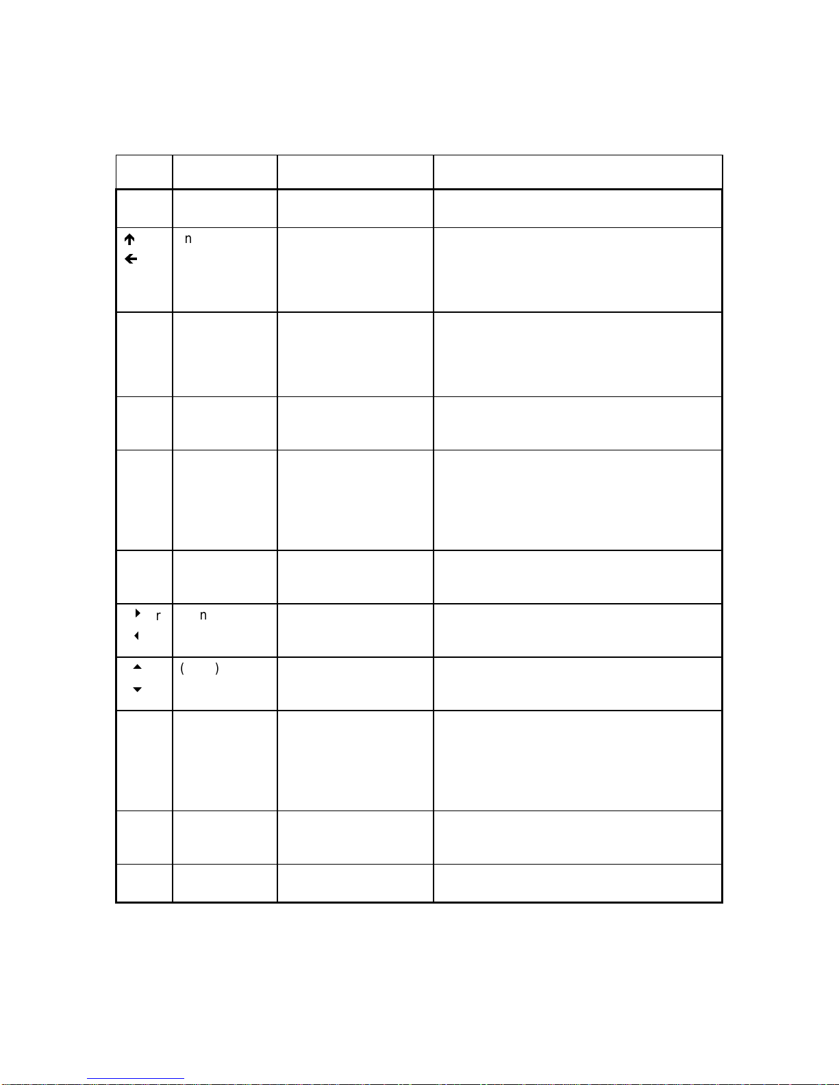
System Setup
The position adjustment commands are described below:
Key Menu Label Action Comments
0 Grip Opens/Closes Gripper Press "0" to release any vial before making
position adjustments
or
(none) Selects Axis to adjust Press an Arrow key to select the axis to
calibrate. Note: before moving the robotic
arm horizontally, choose the vertical axis and
then press "1" Home to move the arm up and
give it clearance above vials in the tray
9 (none) Allows direct entry of
the numeric step value.
After choosing the axis to calibrate, press
"9", then edit the numeric step value.
Pressing ENTER will then command the
instrument to move along the selected axis to
the position of the new numeric step value.
1 Home Commands movement
to the reference
position of the axis
3 Step/Jog Chooses a "step" or
"jog" response when a
motion key is pressed
When calibrating a position, always go to
"Home" on the axis and then move to the
position. This gives an accurate pulse count
In Step mode, pressing a motion key
commands a movement of one step. The
step size is described below. In Jog mode,
the axis motor runs c ontinuously as long as
the motion key is pressed. Jog is used for
long, fast movements.
5 Step Size Allows editing of the
step size for motion in
the Step mode
6 or
4
8 or
2
(none) Directional motion keys
for Left/Right axis
(none) Directional motion keys
for Front/Rear and
Vertical axes
7 Train Calibrates the gripper's
vertical position for
grasping a vial
The step size is relative to the number of
pulses sent to the axis motor. More pulses
gives longer steps resulting in greater travel
The step size is relative to the number of
pulses sent to the axis motor. More pulses
gives longer steps resulting in greater travel
Pressing these keys causes motion if the
Front/Rear axis or the Vertical axis has been
chosen for calibration
When the gripper is above a capped vial in
the tray, choose the vertical axis in the menu,
press "1" to Home, and then "7" to Train. The
gripper will move down until it senses the
cap. This will establish the proper height for
grasping vials
Enter (none) Activates motion,
saves position values
to memory
— (none) Aborts actions and
changes
03-914642-00:6
6-7
Page 63
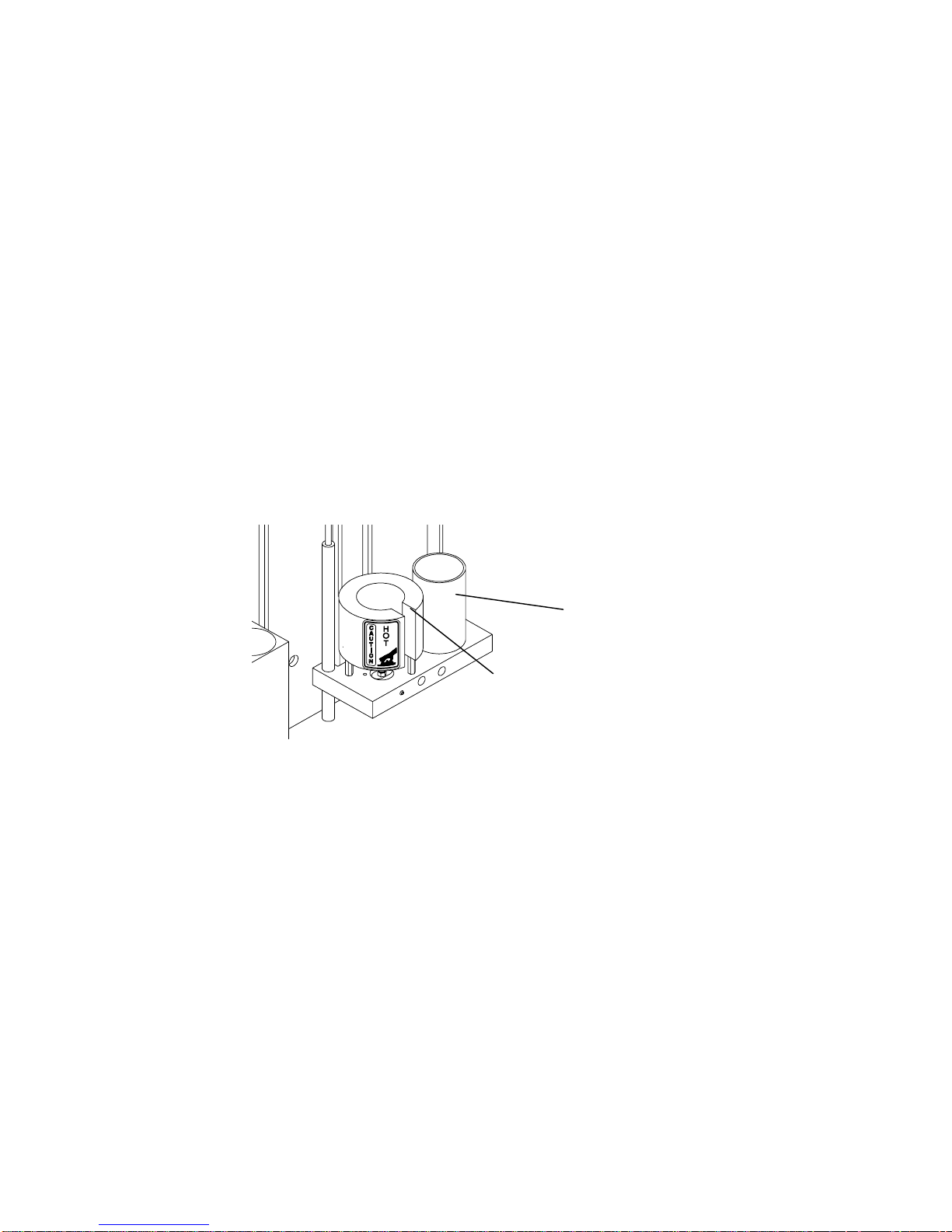
6.4.3 Vial 22 Position
The Vial 22 position is critical bec ause all other tray vial locations ar e determ ined
from this setting. Use the following protocol to recalibrate this position:
1. Pus h the sample tr ay towards the rear of the Archon to m ake s ure the tray is
properly positioned.
2. Place a capped, full vial in sample tray position 22.
3. From the Calibration Setup menu, scroll to the "Vial 22 Position" m enu item
and press ENTER.
4. The Robotic Arm will move and a vers ion of the Coor dinate Settings menu as
described in Section 6.4.8 will be displayed.
5. Press "7" to train the gripper's vertical height for grasping vials.
6. Press “7” again to confirm that the trained position is constant.
7. Pres s ENTER to s ave the position values and com plete the routine. T he arm
will return to its home position.
6.4.4 Water Probe Vial Position
This coordinate setting positions a 40 m l water sam ple vial into the water vial c up
insuring the probe will penetrate the vial properly (see Figure 6-2).
Water Probe Vial
Position (waste block)
Soil Chamber
Figure 6-2
Use the following procedure to recalibrate this position:
1. Place a capped full vial in sample tray position 22.
2. From the Calibration Setup menu, scroll to the "Water Probe Pos" m enu item
and press ENTER.
3. The Robotic Arm will move and the following message will be displayed:
* Water Probe Pos *
Press Enter to get vial 22 for Alignment
or any other key to skip
4. Pres s ENTER. The arm will retrieve the vial, go to the water probe cup and a
version of the Coordinate Settings menu as described in Section 6.4.2 will be
displayed.
5. Press "7" to train the gripper's vertical height for grasping vials.
6. Press “7” again to confirm that the trained position is constant.
6-8
Page 64
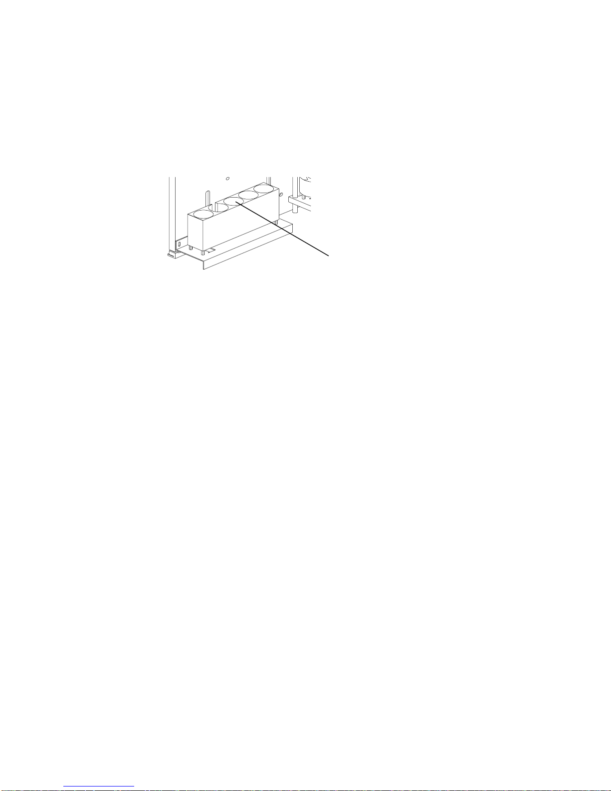
7. Pres s ENTER to s ave the position values and com plete the routine. T he arm
will return to its home position.
6.4.5 Equilibrium Block
This coordinate setting positions the 40 ml water sample vial into the c enter vial
position of the Equilibrium Block . From this point, the other vial positions in the
block are determined (seeFigure 6-3).
Figure 6-3
Use the following protocol to recalibrate this position:
1. Place a capped full vial in sample tray position 22.
2. From the Calibration Setup menu, scr oll to the "Equilibrium Block " menu item
and press ENTER.
3. The Robotic Arm will move and the following message will be displayed:
4. Press ENTER. The ar m will retrieve the vial, go to the equilibrium block area
and a version of the Coordinate Settings menu as descr ibed in Section 6.4.8
will be displayed on the screen.
5. Press "7" to train the gripper's vertical height for grasping vials.
6. Press “7” again to confirm that the trained position is constant.
7. Pres s ENTER to s ave the position values and com plete the routine. T he arm
will return to its home position.
System Setup
Equilibrium Block
Set Point
* Equilibrium Block *
Press Enter to get vial 22 for Alignment
or any other key to skip
6.4.6 Knockoff Clearance
This coordinate setting will allow the gripper with a vial to pass under the Knockoff
plate and into and out of the soil and water sampling positions (see Figure 6-4).
03-914642-00:6
6-9
Page 65

Knockoff plate
clearance
Figure 6-4
Use the following protocol to recalibrate this position:
1. From the Calibration Setup menu, scroll to the "Knockoff Clearance" m enu
item and press ENTER.
2. The Robotic Arm will move and the following message will be displayed:
* Knockoff Clearance*
Press Enter to get vial 22 for Alignment
or any other key to skip
4. Press “1” The arm will go to the equilibrium block plate area and a ver sion of
the Coordinate Settings menu as descr ibed in Section 6.4.8 will be displayed
on the screen.
5. Inspect the positioning of the gripper below the Knockof f Plate. If there is a
clearance of at least 1/16" (2 mm), skip to Step 8 as no adjustment is
necessary. The Knockoff clearance value set at the f actory is 01100. If the
clearance needs to be readjusted, continue with the next step.
6. Press "3" as necessar y to enter the “Step” mode. (This will toggle from step
to jog.)
7. Press a Directional Motion ke y (either "8" or "2") to adjust the clearance.
(If the gripper steps too far, adjust the step size by pressing "5").
8. Pres s ENTER to s ave the position values and com plete the routine. T he arm
will return to its home position.
6.4.7 Standard Clearance
This coordinate setting establishes the correct clearance for the gripper arm to
pass under the glass standard vials when acc ess ing the vial identif ic ation pos ition
in the Equilibrium Block. Use the following procedure to recalibrate this position:
1. From the Calibration Setup menu, scroll to the "Standard Clearance" m enu
item and press ENTER.
2. The Robotic Arm will move and the following message will be displayed:
4. Press “ENT ER” The arm will retrieve the vial, go to the Standard vial area
and a version of the Coordinate Settings menu as descr ibed in Section 6.4.8
will be displayed on the screen.
5. Inspect the positioning of the gripper below the Standard Vial. If there is a
clearance of at least 1/16" (2 mm), skip to Step 7 as no adjustment is
6-10
* Standard Clearance*
Press Enter to get vial 22 for Alignment
or any other key to skip
Page 66

necessary. The standard clearance value set at the f actory is 00970. If the
value clearance needs to be readjusted, continue with the next step.
6. Press a Directional Motion key (either "8 " or "2 ") to adjust the c learance. (If
the gripper steps too far, adjust the step size by pressing "5").
DO NOT ALLOW THE GRIPPER TO CONTACT THE G LASS STANDARD
VIALS.
7. Pres s ENTER to s ave the position values and com plete the routine. T he arm
will return to its home position.
After all calibration steps are performed, r un the Calibration Test to confirm
system operation. Once this is c omplete, press the System k ey twice to exit
the Calibration routine.
6.4.8 Manual Calibration: Coordinate Settings M enu I tems
The remaining menu items of the Calibration Setup menu allow manual
calibration of specific positions of the robotic arm and gripper. These are used
less frequently than the automated routines, primarily in the initial instrument
setup and particular troubleshooting situations. Thes e routines allow the user to
move the arm or gripper increm entally until the user determines that the correct
position has been achieved. The user then saves the position coor dinates to the
Archon memory.
System Setup
The routines also allow the user to directly enter a position value determined by
other means. Note that the original positional settings determined at the f actory
during the instrument's manufacture are recorded on the reference sheet
attached to the inside of the Archon right chassis panel. In certain instances, it
may be useful to directly re-enter these original values through the Manual
Calibration menu items.
When a m anual calibration routine is chosen from the Calibration Setup m enu,
the screen will display a new Coordinate Settings menu of the general format
shown below. The title and other minor features will differ to be appropriate for the
task. The menu allows the user to adj ust positions along one axis at a tim e. The
axis currently addressed is shown on the last (fourth) line with the numer ic step
value of the current position. The sec ond and third menu lines list the num eric
commands for moving the arm or gripper along that axis.
(Keypad display figure)
* (Title will vary) *
1- Home 3-Step (Jog) 0- Grip
5- Step Size xxx 7- Train
Front/Rear xxxxx (Left/Right) (Vertical)
1. Inspect the positioning of the gripper around the vial and determine if the
horizontal positioning along the Left/Right axis or the Front/Rear axis s hould
be improved. If not, skip to Step 7.
2. If the gripper position around the vial is to be recalibrated, press an Arrow key
to select the desired horizontal axis.
3. Press "3" as necessary to enter the Step mode.
4. Press a Directional Motion key to adjust the Gripper position. (I f the gripper
steps too far, adjust the step size by pressing "5").
03-914642-00:6
6-11
Page 67

5. If the other horizontal axis needs to be adjusted, press an Arrow key to select
6. Press an Arrow key to select the Vertical axis
7. Pres s ENTER to s ave the position values and com plete the routine. T he arm
6.5
System Diagnostics
the other axis and adjust the gripper positioning with the appropriate
Directional Motion key.
will return to its home position.
The “
Diagnostics
the Archon to be tested. Verify the motor and its circ uitry is operating properly.
There are no adjustments from this menu, only movement control.
Diagnostics functions will not operate if the Archon is running.
*
System Setup
Menu"
Select the desired menu line with the “2” or “8” key. Press
selected, the screen will display the function (Left/Right Motor, etc.). If the
function is for a "Motor or the Gripper Solenoid", the following message will be
displayed.
Press
completed the display will show it passed.
line and press ENTER. The following menu will be displayed.
ENTER
” menu allows the motors and Remote Input/Output functions of
Note: The
From the
* menu, move the brack ets with the “2” key, to the “
* System Diags *
<Left/right Motor>
Front/rear Motor
Up/Down Motor
Probes U/D Motor
Gripper Solenoid
Remote Inputs
Remote Outputs
(Function Left/Right Motor)
to be tested. Press
Enter to test, Any
other key to abort.
. The selected motor will move back and forth on its axis. W hen
Test Passed. Press
any key to continue.
Diagnostics
ENTER
. Once
Press any key to return to the
If the selected function is for “ Remote Inputs”, the screen will display the current
status of the Input signal from the Purge and Trap concentrator.
Pressing the “2” or “8” key will scroll through the Input signals. They will be
shown on the U/D line. The following is an explanation of the signals.
6-12
*System Diags*
* Remote Inputs *
<U/D >
Status xxx
Standby
Desorb Drain
Emergency Stop
Extra
menu to select another function.
Page 68

System Setup
Standby:
This signal line will verify the status of the Standby signal
received from the concentrator.
Desorb Drain:
This signal line will verify the status of the signal received
from the concentrator to empty the sparge tube during the
concentrator's Desorb step. Most concentrators can send
the signal at either the beginning or the end of the Desorb
step.
Emergency Stop:
This would be an incoming signal to stop the sampling
sequence of the Archon, returning it to the pre start-up
mode. This is a true “stop all” operations function.
Extra:
This is an unused signal line. Possibly for future expansion.
If the selected function is for “Remote Outputs”, the screen will display the
following:
* Remote Outputs *
U/D
L/R
Press Enter to test
This screen allows the relay Output signals to be tested. The line U/D scrolls
through the relay signals. Use the “2” or “8” keys to scroll. The L/R line c hanges
the status of the relay Output from keep“ open" to “closed” pulse. Use the “ 4” or
“6” keys to scroll. The ENTER key is used to “pulse” the signal for test purposes.
Injection Mark
Aux. Output
Soil Vial
Start Purge
03-914642-00:6
The Output signals are:
Injection Mark:
This is a test of the “Inj ection Mark or Star t Out” signal. This
could be used to start the concentrator's purge cycle. Each
time the ENTER key is pressed the relay will operate.
Aux. Output:
Provides a test of the output signal for the Auxiliary Output
relay. This signal would occur per the setting for the Auxiliary
Timer.
Soil Vial:
This is a signal test for an output at the point when the upper
soil probe is inserted into the soil vial.
Start Purge:
This is a test of the signal used to star t the purge cycle on the
concentrator. The signal will occur af ter the sample is loaded
into the sparge tube.
6-13
Page 69

6.6
System Settings
This menu allows the changing of the overall system parameters. These include
temperature settings, motor speeds and acceleration rates, signal polarity, vial gripper
time specifications, delay time and equilibrium data. When the
line is selected, press ENTER, the following menu will appear on the display.
The “System Settings” value may need to be changed depending on the signal output of
the purge and trap or GC / GC/MS. The Settings are defined as follows:
Display Full Name Description
* System Settings
<US Probe Temp XXX>*
XFER Line Temp
US Valve Temp
Gripper Open:
Gripper Closed:
Standby Pol.
DesbDrn Pol.
STOP Pol.
Equib. Count
Equib. Time
*System Settings*
menu
Upper Soil Probe Upper Soil Probe
Temperature.
XFER Line Temp Transfer Line Temperature. This is the temperature setting for the
Upper Soil Valve
Temp.
Gripper Open: Vial Gripper T ime to adjust the delay after the vial
Gripper Closed: Vial Gripper Time to adjust the delay after the vial
Standby Pol. Standby Polarity This sets the input signal from
Upper Soil Valve
Temperature
This is the temperature setting for the
Soil VOC upper probe.
temperature setting of “0” will turn the
heater OFF.
VOC transfer line to the purge and
trap.
“0” will turn the heater OFF.
This is the temperature setting for the
three-way valve attached to the VOC
transfer line, used to stop the helium
purge gas flow during a water purge.
Note:
turn the heater OFF.
Gripper opens.
gripper closes.
shorted Standby signal from the
concentrator (Normally Closed), to an
open (Normally Open) position.
A temperature setting of
Note:
A temperature setting of “0” will
Note:
A
6-14
Page 70

System Setup
DesbDrn Pol. Desorb Drain Polarity This is at the Desorb mode on the
concentrator. This sets the input
signal from shorted (Normally
Closed), to an open (Normally Open)
position.
STOP Pol. Stop Polarity Incoming signal used for the
Emergency Stop. This sets the input
signal from shorted (Normally
Closed), to an open (Normally Open)
position.
Equib. Count Equib. Count This will set the number of positions
to be used in the Equilibrium section
of the Archon.
Equib. Time Equilibrium Time The minimum time the sample will
remain in the Equilibrium section to
reach ambient temperature
The “2 ” and “8” keys will step the brackets to the next menu line. The
numeric keypad is used to change numeric value settings, the “4” and “6”
keys are used to toggle from “Open” to “Closed” on s ignal polarity settings. The
ENTER key will accept the value and toggle to the next line.
Default Operation Value Table
Parameter Factory Default Value Range Allowed
Upper Soil Probe Temp 110C amb-250C
XFER Line Temp 110C amb-250C
Upper Soil Valve Temp 95C amb-132C
Gripper Open: 750 0-999 milliseconds
Gripper Closed: 999 0-999 milliseconds
Standby Pol. CLOSED CLOSED/OPEN
DesbDrn Pol. CLOSED CLOSED/OPEN
STOP Pol. CLOSED CLOSED/OPEN
Equib. Count 0 0-5
Equib. Time 0 0-999
03-914642-00:6
6-15
Page 71

6.7
System Options
The *System Options* menu allows f or enabling optional features of the Archon.
When *System O ptions* is selected, the following menu is displayed. The “2”
and “8” keys are used to scroll through the menu lines. The “4” and “6”
keys are used to toggle the “NO - YES" response. The ENTER key will accept the
selection. Note: The following menu shows the system default settings as
shipped from the factory.
* System Options *
<Barcode Scanner?
Needle Sparge?
Ign. Vial Type
Ignore No Vial?
Hot Water Rinse?
Vial Checks?
Beep on Error
NO
YES
NO
YES
YES
YES
YES
>
Barcode Scanner:
Needle Sparge:
Ignore Vial Type:
If the Archon is equipped with an optional Barcode
Scanner, answering “YES” will tell the Archon Robotic
Arm to place the sample vials in the Barcode Scanner
Zone prior to vial type detection. The barcode label on the
vial will be read and the information m ay be retrieved to a
PC for its use. Only one barcode label will be retained for
each vial position.
If the Archon is setup for Needle Sparge sampling, this
option must be “YES.” The sample vial type sensor will
then be reversed to detect water (40 ml VOC) vials. If a
SoilVial is detected, an error will be reported.
This option disables the sample vial sensor . W hen “YES"
is selected, only the “sample type" parameter will
determine the sampling loc ation. See “Method Setup” for
further details.
CAUTION
6-16
If “YES is selected, SEVERE damage will occur if the
sample tray is not loaded correctly. SoilVials and W ater
vials MUST be installed per the Sample T ype parameter.
See Section 5.2 Method Parameters for more details.
See Section 1.5 for vial types
Page 72

System Setup
Ignore No Vial:
Hot Water Rinse:
Vial Checks:
Beep on Error:
When this option is “YES,” tray positions that have no
vials will be ignored. The Gripper “No Vial” sensor will
always be used to detect the presence of a vial and the
potential of lost vials in transit. The default should be
“NO”.
When this option is “YES”, the “Hot Water" reservoir is
heated during the syringe and sparge tube rinses. This
reservoir is located inside the rear or the unit. Water
passes through the heated reservoir prior to entering the
25 ml syringe and sample transfer lines.
This option will cause the Robotic Arm to search the
equilibrium and vial sampling locations for vials during
start-up. The Archon will remove the vials and return
them to the sample tray.
CAUTION
This option should be set to “YES” to prevent vial jams.
This option causes the Archon to produce an audible
“Beep” when a System error occurs. The beep will sound
every five seconds. This would be anything which may
interrupt or stop the sample run. If a problem occurs and
the Archon “Beeps”, immediate action must be taken to
resolve the problem. An error message should be
displayed indicating the problem.
03-914642-00:6
6-17
Page 73

6-18
Page 74
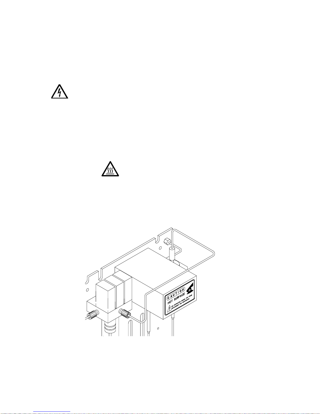
7 Maintenance
This section describes maintenanc e procedures for the Archon, including how to
change the soil and water probes and soil transfer line.
WARNING:
SHOCK HAZARD
When cleaning any components of the Arc hon, e.g., exterior, r obotic slide rods or
leadscrews, gripper arms or sample tray, use only an isopropanol and water
solution placed on a lint-free and oil-free cloth.
7.1
Removal and Replacement of the Needle Sparge or SoilVial Probe
Service to the Archon should only be performed by qualified
service personnel. Before any service is performed, turn the
instrument OFF and remove the main power cord. Allow
sufficient time for all heated zones to cool before
proceeding.
WAR NING:
The cover and probe are hot.
.)
(1)
(Refer to
Removal
1. Loosen the #4-40 socket head screw securing the cover
BURN HAZARD
Figure 7-1, Figure 7-2
cover.
, and
Figure 7-3
. Remove the
Figure 7-1
03-914642-00:6
1 Cover
7-1
Page 75
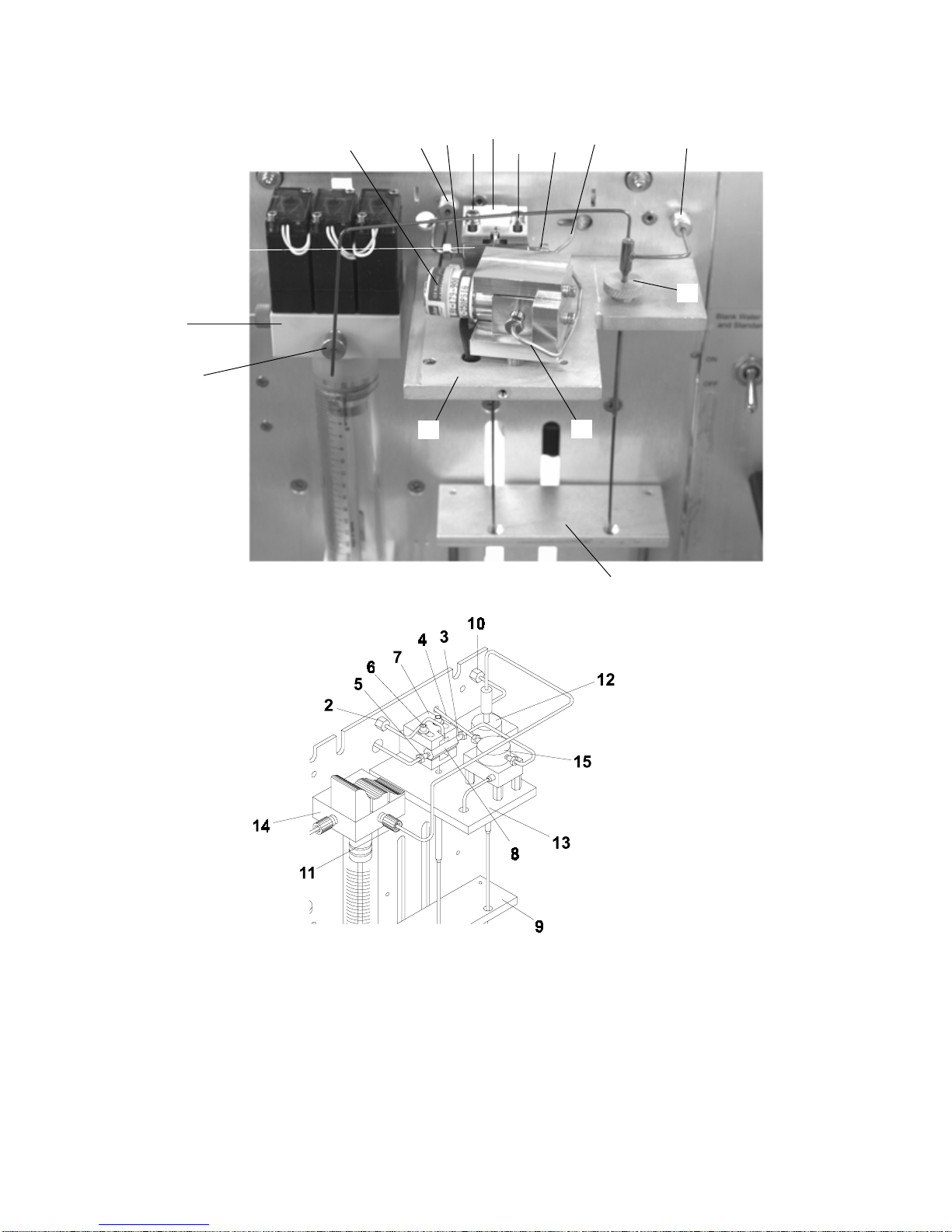
14
11
5
15
8
2
7
6
6
4
3
10
12
Figure 7-2
13
16
9
Figure 7-3
Cover (See Figure 7-1).
1
Bulkhead nut
2
Sample out line (shor t line)
3
soil transf er line (and nut)
4
Helium flush line
5
#4-40 Screws
6
Probe retainer
7
Probe body
8
7-2
9
10
11
12
13
14
15
16
Knock off plate
Gas line and nut
Reverse ferrule/ S uper Flangeless nut/ferrule
Retaining nut
Mount plate
Valve manifold
Upper soil valve
Short line
Page 76

2. W ith a 1/4" wrench, loosen the nuts on the sample out line (3) and on the
helium flush line (5). Remove the lines from the probe.
3. W ith a 5/16" wrench, loosen and remove the bulk head nut (2) with line, on
the helium purge gas / water in line.
4. Loosen the two #4-40 s crews (6) securing the probe retainer (7). Slide the
cover back exposing the probe body (8). Pull the probe body up, out of the
housing and out of the knockoff plate (9).
Replacement
1. Insert the probe into the mount plate (13) and down through the knockoff
plate (9), (needle sparge only). (Soil probe will not insert thr ough knockoff
plate).
2. Push the body of the probe (8) into the heated housing, slide the retainer
forward, tighten the two # 4-40 screws (6).
3. Attach the sample out line (3) and the helium flush line (5).
4. Attach the 5/16" nut (2) to the bulkhead fitting for the helium purge/water
supply line.
Maintenance
5. Be certain all fittings are tight, snug and 1/4 turn.
6. Replace the cover.
7.2
Removal and Replacement of the Water Probe
(Refer to Figure 7-2 and Figure 7-3.)
Removal
1. With a 5/16" wrench, loosen and remove the brass nut securing the
pressurizing gas line (10).
2. Remove the blue plastic nut with reverse ferrule (11) securing the water line.
3. Loosen the retaining nut (12) securing the probe to the mount plate (13).
4. Lift the probe up and out.
Replacement
1. Slide the tip of the probe into the hole in the mount plate (13) and into the
hole in the knockoff plate (9).
2. Finger-tighten the retaining nut (12).
3. Attach and tighten the 5/16" brass nut securing the press urizing gas line (10)
to the bulkhead fitting.
03-914642-00:6
7-3
Page 77

4. Attach the flangeless f itting and ferrule (11) into the hole in the center of the
valve manifold (14). Be c ertain the line, with ferrule, is seated all the way to
the bottom of the hole. Finger-tighten the nut.
7.3
Cleaning the Soil Transfer Line Frit (PN DY-505599-00)
(Refer to Figure 7-2 and Figure 7-3)
Removal
1. Remove the soil probe as described in Section 7.1.
2. Blow into the left side with about 40-50 psi of clean air or nitrogen.
Installation
1. Install the probe as described in Section 7.1.
2. Be certain all fittings are tight.
7.4
Replacement of the Water Line Screen (P/N DY-505598-00).
(See Figure 7-2 and Figure 7-3).
1. Remove the flangeless fitting and ferrule (11) from the valve manifold (14).
2. Using a small diam eter pick or pointed wire, reach into the hole and pull the
screen out.
3. Insert the screen into the hole, the white side of the screen faces out.
4. Insert the flangeles s fitting and ferrule (11) into the hole in the manifold (14).
Finger-tighten the nut.
7.5
Replacement of the Soil Transfer Line
(Nickel Line Only) (DY-505745-00)
(See Figure 7-2 and Figure 7-3).
Removal
1. Remove the upper s oil valve cover shown in Figure 7-1. Refer ring to Figure
7-2 and Figure 7-3, loosen and remove the nut (4) securing the transfer line
to the upper soil valve (15).
2. If necess ary, remove any covers from the purge and trap, allowing access to
the fitting on the end of the transfer line. Disc onnect the line from the purge
and trap.
3. Cut one end off, with fitting, from the line.
4. Slide the line out of the heater's sheath.
Replacement
1. Uncoil and straighten the new line. Insert the line into the heater's sheath.
Carefully slide the line all the way through until it is inside the cabinet. Blow
through the line with helium before connecting.
7-4
Page 78
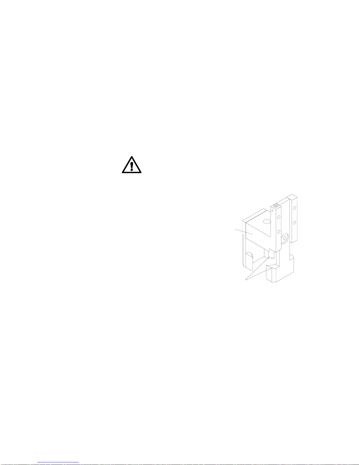
2. Slide the Valco nut and a compression ferrule set onto the new line. Insert the
6
line, with nut and ferrule into the upper soil valve (15). Using a 1/4" open
wrench tighten the nut.
3. Attach the other end to the purge and trap using whatever fittings are
required.
4. Recheck the fittings. Install all the covers.
7.6
Replacement of the Soil Purge Gas Needle (DY-505463-00)
1. Remove the sample tray.
2. Park the Robotic Arm in the "Front.” See Section 6.1
3. Us ing a 5/16" nut driver or deep soc ket loos en the br ass nut and rem ove the
needle.
4. Replace the needle and tighten with the 5/16" wrench. Do not overtighten.
Maintenance
CAUTION
7.7
Cleaning the Vial Gripper
Approximately once a month, the vial gripper arms
(17), should be wiped clean. This will insure the
gripper's arms hold the vial properly.
1. Move the robotic arm to “Front Park.” See
Section 6.1.
2. Use a soft tissue or a cotton swab with 30%
isopropanol in water, and wipe the rubber
gripper pads.
3. Press ENTER to move the arm back to “Home.”
7.8
Leak Check Helium Purge Gas Flow
(Refer to Figure 7-2 and Figure 7-3).
Do not use any tools and do not
overtighten.
Vial G ripper
Vial Gripper
(17)
Arms
1
Figure 7-4
Section 2.12 described the helium purge gas flow adjustment, however, if the flow
rates, out of the host purge and trap's vent and the bulkhead fitting (2) do not
match, a leak exists. Use the following procedures to locate the helium leak.
First, check each fitting in the flow path using isopropanol and water. The leak
may only be a loose fitting. If all the fittings are leak tight, continue to the following
steps.
03-914642-00:6
7-5
Page 79
WAR NING:
BURN HAZARD
Components may be hot! Be certain the
“UPPER SOIL PROBE TEMP” and “UPPER SOIL
VALVE TEMP” are OFF and the parts are cool
before continuing.
1. Remove the soil probe cover. Disconnect the short line
heated upper soil valve
Load a clean vial with a new septum in the tray and run it as a manual soil
sample. Check the flow rate out of the line. It should be the sam e as the f low
from the soil probe bulkhead nut
2. If the two flow rates are not equal, replace the vial and septum and repeat the
soil purge. If the flows still do not m atch, the soil pr obe m ay be dam aged and
should be replaced. See Section 7.1.
3. If the f lows do match, chec k the flow com ing out of the upper soil valve
A “jig” should be made to test the flow. Remove the transfer line
upper soil valve. Using a 2-3" (5.0 cm - 7.5 cm ) piece of 1/16" OD stainless
steel tubing, a Valco nut and a two piece compress ion ferrule, insert the jig
into the valve and tighten. Measure the purge flow out of the jig. The flow
should be equal to the flow from the shortline
4. If the flows do not match, the upper soil valve is leaking, and it should be
replaced.
5. If the flows do match, the fitting on the end of the soil transfer line in the
purge and trap may be leaking, or a leak exists within the purge and trap.
6. Reattach the transfer line into the upper soil valve and recheck the flow at the
host purge and trap vent. If the flows do not match, check the fitting, on the
soil transfer line, in the purge and trap, and leak check the host purge and
trap per its recommendations.
7. Using isopropanol and water, recheck all the fittings again to insure that they
are leak tight. Once these steps have been completed and the flow rates now
match, the system is leak tight and ready for use.
. Attach the tubing from a flow meter to the line.
(15)
.
(2)
.
(6)
going into the
(16)
(4)
(15)
from the
.
Replacement of the Heated Upper Soil Valve
7.9
Use the following procedure to replace the upper soil valve, refer to Figure 7-2
and Figure 7-3.
WARNING:
SHOCK HAZARD
1. Turn off the power to the instrument and remove the power cable.
2. Remove the rear panel by loosening the two quarter-turn fastener s loc ated at
the top of the panel.
3. Rem ove the Upper Soil Valve cover by loosening the front screw with a 3/32”
Allen wrench. Also, remove the upper soil probe.
4. Loosen and rem ove the two 1/16” lines
wrench. Remove the three screws under the valve plate
screws on the right of the valve.
7-6
Disconnect instrument from power source
before proceeding.
installed in the valve using a ¼”
(16)
and the two
(13)
Page 80

5. Trace the valve wires to the rear panel and unplug the connector. Cut off the
old connector, then remove the valve (15) from its mount.
6. Install the new valve in the reverse order. Run the valve wires through the
back panel then attach the connector. Reins tall the probe, upper soil valve,
and cover. Reinstall the power cord and turn the power back on.
Note: In Figure 7-3 when removing Angar valve you must rem ove metal plate
under mount plate (13). Remove insulated divider then remove three
socket head screws on top of mount plate.
7.10
Sample Stir Motor Speed Adjustment
The speed of the sample stir motor may be increased or decreased by the
adjustment of a pot. A s mall jeweler's screwdriver ( 1/16" flat blade or Phillips) is
required.
1. Loc ate the pot access hole, on the r ear panel of the Arc hon on the upper lef t
side. The hole is below the 9-pin “D” connector labeled “Remote RS-232.”
2. Start a manual sample. Be certain the stir motor is turned “ON” in the
method.
Maintenance
3. Insert the screwdriver into the hole and rotate the pot, CW will increase the
speed and CCW will decr ease the speed. Observe the response on the stir
motor magnet.
Only slight pressure is necessary. Do not push hard
CAUTION
4. Once the speed is adjusted, stop the run.
with the screwdriver as damage may occur.
Stir Motor
Adjustment Hole
Figure 7-5
03-914642-00:6
7-7
Page 81
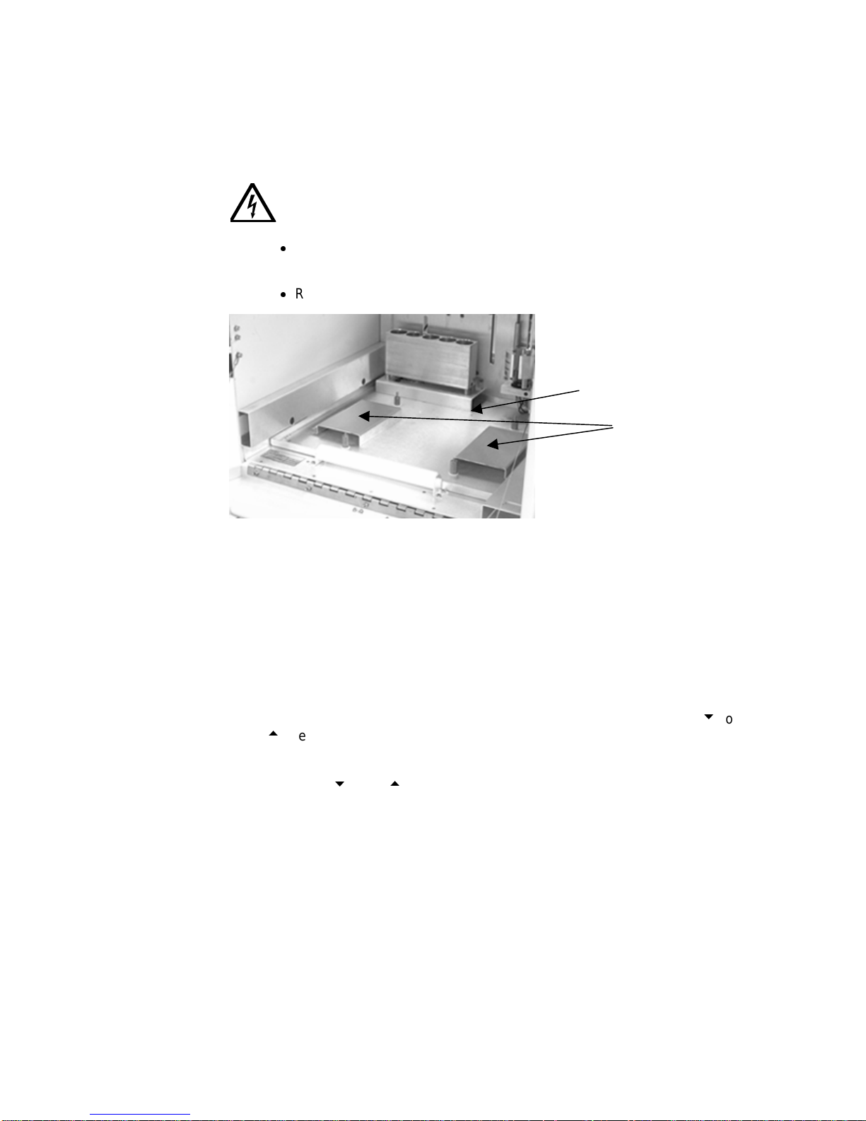
7.11
Drip Pan Cleaning
The drip pan, located under the sample tray, should be cleaned occasionally to
prevent or remove any algae buildup.
WARNING:
SHOCK HAZARD
Wipe the pan and clean the drain hole with a pipe cleaner or a small
brush.
Restore power to the unit.
Figure 7-6
7.12
Cleaning or Replacing the Syringe Plunger O-ring
Disconnect instrument from power source
before proceeding.
Drip Pan Fittings
Tray Supports
The 26 ml syringe plunger assem bly
plunger assembly must be r emoved from the glass syringe barrel to acc omplish
this. Refer to Figure 7-7.
1. Turn the helium flow Toggle Switch “OFF.”
2. Start from the main Arc hon menu. Press the “System” key. Using the “2” or
“8” key, scroll through the menu selec tions until the “Maintenance” line is
selected. Pre ss ENTER.
3. Using the “2” or “8” key again, scroll through the menu until the “ Clean
Syringe” line is selected. Press ENTER, the gripper will move to the f ront and
the following menu will be displayed. Follow the instructions and remove the
thumbscrew
4. The display will show “Clean Syringe” while the plunger arm
down. When the movement stops the display will show the following
from the bottom of the plunger arm
(2)
Remove thumbscrew.
Press any key to continue.
Remove the 2 screws
from lower block
Press any key to continue.
should be cleaned once a month. The
(1)
.
(3)
is moving
(3)
(4)
7-8
Page 82

Maintenance
5. The following menu will be displayed.
Remove syringe
Pull down carefully
Press any key to continue.
Gently pull the syringe barrel down off the valve manifold assembly (6).
Examine the plunger and o-ring for any corrosion or damage. If the o-r ing has
been leaking or there is obvious damage to the o-ring, it should be replaced.
Remove syringe
Pull down carefully
Press any key to continue.
7. If the o-ring requir es only cleaning, rinse the plunger assembly with a diluted
(50:50) solution of acetic or nitric acid, followed by rinsing the plunger with
very warm water and drying it with air or nitrogen. This will r emove any Teflon
particles from the o- ring and any salt deposits on the plunger body. Rinse the
inside of the glass barrel with water and wipe it dry with a soft tissue. Note:
Make sure the barrel and plunger are free of any buildup
8. If the o-ring needs replacement, remove the old o-ring from the plunger.
Warm the new o-ring in very hot water for several minutes. T he new o-ring
will slide on the plunger from the rear. W ith ONLY your fingers, gently push
the o-ring into the plunger's groove. Do not scratch the o-ring with your
fingernails.
NEVER
use a tool. Note: Make sure the barrel and plunger are
free of any buildup
9. W et the top end of the 26 ml syringe glass barrel and the plunger assem bly
with warm water. Gently push the plunger back into the barrel.
10. Press any key and the following menu will be displayed.
Install syringe
push up carefully
Press any key to continue.
Carefully align plunger along axis of glass barrel
WARNING
and do not force the plunger as breakage may
occur.
11. Replace the barrel with the plunger assembly back up onto the valve manifold
assembly. Push it up VERY gently. Reinstall the support block with the two
Allen socket head screws.
12. Press any key. The display will show “Clean Syringe” and the plunger rod arm
will begin to move up. The following menu will be displayed.
Align plunger rod
in plunger arm.
Press any key to continue.
03-914642-00:6
7-9
Page 83

13. The plunger rod arm will stop about ½" from the
bottom of the plunger rod (5). Gras p the plunger rod
with your fingers and pull it down into the hole in the
arm (3).
14. Press any key. The display will now show the
following menu. Replace the thumbsc rew then press
any key.
Replace thumbscrew.
Press any key to continue.
15. The display now shows “Clean Syringe” and the
plunger will move up. The vial gripper will m ove bac k
to the home position. Press the System k ey twice to
exit back to the main Archon menu.
Turn the helium toggle switch "ON.” The Archon is
now ready to begin running samples.
1
2
3
7.13
(Refer to Figure 7-8).
If the recovery of the internal standard(s) appears to
be too low or is erratic, the lines to and from the
internal standard valve and the valve rotor should be
cleaned. The following steps detail the cleaning
maintenance procedure. A 1/4" open end wrench is
necessary.
Syringe Plunger Assemby
Thumbscrew
Plunger Arm
4
5
6
Cleaning the Internal Standard Valve and Lines
Screws
Plunger Rod
Valve manifold Assembly
Turn the helium gas OFF with the toggle switch,
(refer to Figure 7-10).
1. Remove the reservoir vial (1) or
(2). Disc onnect the pickup tube (3
or 4). From the Valco valve, blow
through the pickup valve tubes
with 40-50 psi nitrogen or helium.
Figure 7-7
2. Disconnect the two waste lines (5
or 6) from the Valco valve.
1
2
3
4
5
6
7-10
Reservoir vial #1 DY-505484-00
Reservoir vial #2 DY-505484-00
Pickup tube DY-700020-00
Pickup tube DY-700020-00
Waste lines DY-700017-00
Waste lines DY-700018-00
7
8
9
10
11
Figure 7-8
Lines DY-505502-00
Lines DY-505501-00
Knuled retaining knob
Valve DY-505407-00
Thumb nut
Page 84

Maintenance
3. Blow through the lines with clean nitrogen or helium.
4. Remove the two lines (7or 8) from the bottom of the valve. These two lines
are water/sample supply lines to and from the valve m anifolds. Unscrew the
lines from the m anifold assemblies and using c lean nitrogen or helium blow
through the lines.
5. Uns crew the knurled r etaining knob (9) on the front of the valve body. Do not
use an Allen wrench.
6. W ith a sm all pick ( the tool used to remove a G C septum work s well) rem ove
the valve rotor. If this is not possible try a small magnet. Note the position of
the groove (loop) on the rotor. It MUST be facing down.
7. Blow through the valve (10) f rom the fr ont using clean nitrogen or helium . Be
certain there is flow coming out of each hole.
8. Reattach all the lines to their proper locations. Be certain all the f ittings are
tight.
9. Insert the r otor into the valve.
Install the knurled knob. Using your fingers, tighten the k nob until it will no
longer rotate.
10. Turn the helium toggle switch to “ON.”
Note:
If it is necessary to remove the 5 ml standard reservoir vials, be very
certain the helium toggle switch is off. Grasp the vial before rotating the black
thumbnut (11).
Installation of the Internal Standard Vials
7.14
Before beginning a sample run, be cer tain the 5 ml Standard Vial(s) are filled with
the required internal standard or surrogate.
To fill the vials:
1. Turn the helium gas “OFF” with the toggle switch.
2. Grasp the vial and loosen the black thumbnut. Slide the vial with Thumbnut
and ferrule down clearing the pickup tube.
3. Clean the vial, dry it thoroughly and fill the vial with approximately 5 ml of
standard and / or surrogate.
4. Remove black thumbnut, slide over neck of vial with 3/8” Teflon ferrule (P/N
28-694637-00). Then slide the vial up into standard mount. Finger-tighten
until it is snug.
BE SURE THE GROOVE IS FACING DOWN!
03-914642-00:6
CAUTION
Do not use any tools and do not
overtighten.
7-11
Page 85

Standard
Mount
Black
Thumbnut
Figure 7-9
5. Return the toggle switch to the ON position.
Prime the lines as described in Section 6.3.1.
5mL
Reservoir Vials
Figure 7-10
7.15
Shipping Instructions
If the Archon must be s hipped, the “Shipping Positions” m enu must be ac cessed
to set the Archon in its correct shipping mode. Press the “System” key, scroll
down to the *System Maintenance*, menu line “Shipping Positions.” Press
ENTER, the display will now show “Shipping Positions”, then:
The robotic arm will m ove to the shipping location, the 26 m l syringe plunger will
lower and the sample elevator will be raised. Once all movement has ceased,
turn the power off, unplug the power cord, rem ove the sam ple tray and install the
shipping screw and spacer through the left s ide into the robotic arm. The Archon
is now ready to be packaged and shipped.
CAUTION
7-12
“Remove tray
Remove Power.”
The shipping screw and spacer must be installed or serious
damage will occur!
Page 86

8 Remote I/O Cable Hookup Instructions
The following drawings are to be used to interface the Archon to the purge and
trap and or gas chromatograph. The interface will allow the Archon, the purge and
trap, and the GC to send and receive correct signals such as the GC ready and
remote start. Each m ake and model purge and trap and GC will have slightly
different I/O connections, therefore, refer to the dr awing which is specific to your
system.
WARNING:
SHOCK HAZARD
If any panels must be removed to make cable installations, turn the power
off and unplug the instrument.
Archon REMOTE I/O connector signal pin-outs.
Pin Number Signal Wire Color
1 Logic Ground Black
2 Logic Ground Brown
3 Logic Ground
4 Logic Ground
5 Start Purge (no), Relay Output Red
6 Start Purge (nc)
7 Soil Purging (com)
8 Aux Output (no)
9 Aux Output (nc)
10 Soil Purging2 (com)
11 Serial Output Reserved
12 Serial Clock Reserved
13 Serial Load Reserved
14 Standby (L), Signal Input Blue
15 Drain (L), Signal Input Green
16 Emergency Stop (L)
17 Spare Reserved
18 Start Purge (com), Relay Output White
19 Soil Purging (no)
20 Soil Purging (nc)
21 Aux Output (com)
22 Soil Purging2 (no)
23 Soil Purging2 (nc)
24 not used
25 +5 Vdc Reserved
NOTE: All pin outs in
03-914642-00:6
Bold
are used on the Archon cables.
8-1
Page 87

8.1
Archon to Tekmar LSC-2000 and 3000, P/N DY-505872-00
Male
Female
Pin Outs
Remote I/O
Archon Color Tekmar Function Color
IN OUT
Desorb
Drain
Green 24 3 GC Ready Green #6 Spade Term.
15
Brown 23 4 GC Ready White #6 Spade Term.
2
Red
Black
Start
Purge
P&T
Ready141
The DIP switch UO12 settings in the LSC 2000 must be as follows; 3 OPEN and 4
Note:
Red 1 21 GC Start Red #6 Spade Term.
5
White 2 22 GC Start Black #6 Spade Term.
18
Blue 16 21 Start Red
Black 15 22 Start Black
CLOSED. All others CLOSED. DIP switch UO13 all OPEN.
For a 3000 installation, the Tekmar GC Port must be specified.
1. At the Standby Screen, press the key labeled “CONF.”
2. At the Configuration Screen, press A (GC I/O Port). The GC Port Screen appears.
3. Choose Standard. GCType =63. Press ENTER to save the selection.
4. Turn the instrument off.
The Tekmar 3000 must be programmed to give a switch closure at purge ready. This switch
closure will initiate the Archon to begin the sample Cycle. Select method 14 to provide correct
polarity settings for the purge ready output. If another method is selected please refer to the
Tekmar manual for additional information.
Connect the cable to the Archon and to the purge and trap.
secure the connector to the chassis.
The spade terminals will attach to the GC and Data
Be certain the locking screws
System at their appropriate connections. Refer to your GC and Data System manuals f or correct
connector locations.
8-2
Page 88

Remote I/O Cable Hookup Instructions
8.2
Archon to Tekmar 3000 with HP 5890, P/N DY-505869-00
Male
Female
Pin Outs
Remote I/O
Archon Color Tekmar Function Color
IN OUT
Desorb
Drain
Green 24 3 GC Ready Green 5
15
Brown 23 4 GC Ready W h ite 9
2
Red
Black
HP
5890
Start
Purge518
P&T
Ready141
The DIP switch UO12 settings in the LSC 2000 must be as follows; 3 OPEN and 4
Note:
Red 1 21 GC Start Red 1
White 2 22 GC Start Black 2
Blue 16 21 Start Red To
Black 15 22 Start Black Data System
CLOSED. All others CLOSED. DIP switch UO13 all OPEN.
For a 3000 installation, the Tekmar GC Port must be specified.
1. At the Standby Screen, press the key labeled “CONF.”
2. At the Configuration Screen, press A (GC I/O Port). The GC Port Screen appears.
3. Choose Standard. Press ENTER to save the selection.
4. Turn the instrument off.
The Tekmar 3000 must be programmed to give a switch closure at purge ready. This switch
closure will initiate the Archon to begin the sample Cycle. Select method 14 to provide correct
polarity settings for the purge ready output. If another method is selected please refer to the
Tekmar manual for additional information.
Connect the cable to the Archon and to the purge and trap.
secure the connector to the chassis.
The 12-position connector will connect to the HP 5890
Be certain the locking screws
and the red and black to the Data System. Refer to your GC and Data System manuals for correct
connector locations.
03-914642-00:6
8-3
Page 89

8.3
Archon to Tekmar LSC 2000/3000 with Varian 3400/3600
P/N DY-505868-00
Male
Female
P23
Red
Black
Pin Outs
Remote I/O
Archon Color Tekmar Function Color
IN OUT
Desorb
Drain
Start
Purge
P&T
Ready141
Note:
15
2
5
18
The DIP switch UO12 settings in the LSC 2000 must be as follows; 3 OPEN and 4
Green 24 3 GC Ready Green
Brown 23 4 GC Ready White
Red 1 21 GC Start Red
White 2 22 GC Start Black
Blue 16 21 Start Red To
Black 15 22 Start Black Data System
J23-J16
Varian Motherboard
3
P23
1
4
P16
3
CLOSED. All others closed. DIP switch UO13 all OPEN.
For a 3000 installation, the Tekmar GC Port must be specified.
1. At the Standby Screen, press the key labeled “CONF.”
2. At the Configuration Screen, press A (GC I/O Port). The GC Port Screen appears.
P16
3. Choose Standard. Press ENTER to save the selection.
4. Turn the instrument off.
The Tekmar 3000 must be programmed to give a switch closure at purge ready. This switch
closure will initiate the Archon to begin the sample Cycle. Select method 14 to provide correct
polarity settings for the purge ready output. If another method is selected please refer to the
Tekmar manual for additional information.
Connect the cable to the Archon and to the purge and trap.
secure the connector to the chassis.
3400/3600 GC motherboard at connector s J23 and J16. T he grounding clam p should be secured
to the GC chassis. Attach red and black wires to the Data System. Refer to your GC and Data
System manuals for correct connector locations.
Note: Make sure to select Aquatek 50.
8-4
Be certain the locking screws
The connectors P23 and P16 will connect to the Varian
Page 90
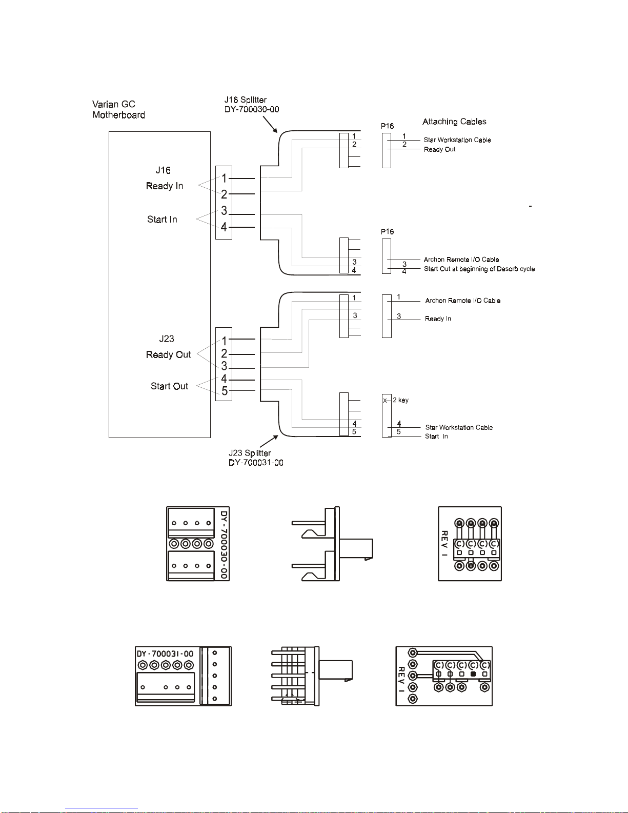
Remote I/O Cable Hookup Instructions
8.3.1 Varian GC Motherboard Attachments – J16 and J32
8.3.2 J-16 Splitter DY-700030-00
8.3.3 J-23 Splitter DY-700031-00
03-914642-00:6
8-5
Page 91

When connecting to a Varian series 3400 or 3600 GC with Star Workstation, connectors from
both the Archon I/O cable and the Star Workstation cable must access the J16 and J23
connectors on the GC motherboard. This is possible using the J16 Splitter (DY-700030-00) and
the J23 Splitter (DY-700031-00) following the instructions below:
1) Turn off the power and unplug the power cord f rom the GC. Remove the top panels
to allow access to the GC motherboard.
2) Route the GC-end of the Arc hon I/O cable and the GC-end of the Star W orkstation
cable through the back panel of the GC (see Star Workstation installation diagram).
3) Connect the 5-pin female Molex connec tor (P-23) from the Star Workst ation cable to
the male connector on the J-23 Splitter with 4 pins (the #2 position lacks a pin).
4) Connect the 5-pin female Molex connector from the Archon I/O cable to the 5-pin
male connector on the J-23 Splitter.
5) Connect the J-23 Splitter to the J-23 connector on the GC motherboard (see GC
manual for motherboard layout schematic).
6) Connec t the 4-pin female Molex connector from the Archon I/O cable to either of the
4-pin male connectors on the J-16 Splitter.
7) Connect the 4-pin female Molex connec tor (P-16) from the Star Workst ation cable to
either of the 4-pin male connectors on the J-16 Splitter.
8) Connect the J-16 Splitter to the J-16 connector on the GC motherboard (see GC
manual for motherboard layout schematic).
9) Complete the installation of the Archon I/O cable and of the Star Work station cable
according to the standard instructions for those cables.
Technical Note: The following sequence occurs when the Archon and a Purge and T rap unit is
configured with the Varian 3400 and 3600 GC with Star Workstation:
1) The Archon begins its sample handling after receiving a Ready signal from the Purge
and Trap unit. As configured above, the Purge and Trap goes to Ready without
waiting for the GC. This allows the user to prepar e the GC or W orkstation while the
sample is being purged and collected in the Purge and Trap.
2) The Purge and Trap collects the purged sample onto its trap and waits for a Ready
signal from the GC. This occurs after the Workstation issues a Ready signal to the
GC through the Workstation’s cable plug attached to the GC’s J-16 “Ready-In” pins,
1 and 2. In turn, the GC sends a “Ready-Out” signal from its J-23 pins 1 and 3 into
the Archon I/O cable.
3) When the Purge and T rap has both com pleted its purge cycle and detec ted a Ready
signal from the GC, the Purge and T rap desorbs the s ample from its trap and issues
a “Desorb-Out” signal to both the Archon and to the Var ian GC. This signal travels
through the Remote I/O cable supplied with the Archon.
4) The Desorb- Out s ignal f rom the Purge and Trap starts the Arc hon’s “AutoDr ain” c ycle
which drains the sparge vessel if a water-sample method is being run on the Archon.
5) The Desorb-Out s ignal simultaneously travels through the Archon Remote I/O cable
to its connector attached to the GC’s J-16 Start-In pins, 3 and 4, and initiates the GC
run. The GC in turn initiates a “Start-O ut” signal through J-23 pins, 4 and 5, which
triggers the Workstation to begin data collection.
8-6
Page 92

8.4
Archon to Tekmar LSC 2000 / 3000
GC/MS with HP-1000/RTE GC/MS Software, HP 5890 MSD RTE (RTE-A, RTE-6, or Rev
F2), P/N DY-505876-00
Female
Remote I/O
Archon Color Tekmar Function Color Connection
IN OUT
Desorb
Drain152
Green 24 3 GC Ready Red 25 / 27
Brown 23 4 (Slave) GC Ready Black 26 / 28
Remote I/O Cable Hookup Instructions
with HP 5895/96/85/87/88/92
Male
Pin Outs
Start
Purge518
P&T
Ready141
The DIP switch UO12 settings in the LSC 2000 must be as follows; 3 OPEN and 4
Note:
Red 1
White
Blue 16 21 GC/MS Remote Start Button
Black
2
15 22
(Master)
GC/MS Remote Start Button
CLOSED. All others closed. DIP switch UO13 all open (If you are using the Master Cable or if
you are using Revision F or greater switch 5 is to be CLOSED.
For a 3000 installation, the Tekmar GC Port must be specified.
1. At the Standby Screen, press the key labeled “CONF.”
2. At the Configuration Screen, press A (GC I/O Port). The GC Port Screen appears.
3. Choose Standard. Press ENTER to s ave the selection. (Master m ode) or user, G C Type=32
(slave mode).
4. Turn the instrument off.
The Tekmar 3000 must be programmed to give a switch closure at purge ready. This switch
closure will initiate the Archon to begin the sample Cycle. Select either method 14 or 15, to
provide correct polarity settings for the purge ready output. If another m ethod is selected pleas e
refer to the Tekmar manual for additional information.
Connect the cable to the Archon and to the purge and trap.
secure the connector to the chassis.
The Tekmar unit can be operated in one of two m odes: Master mode or Slave mode. In Master
mode, the Tekm ar unit commands or signals the GC/MS or data system to start processing a
03-914642-00:6
Be certain the locking screws
8-7
Page 93

sample. In Slave mode, the GC/MS or data s ystem c ommands or signals the T ek mar unit to start
processing a sample.
This interface has two cables , Master and Slave control. If you install the Master cable, the unit
will operate in Master mode. If you install the Slave control cable, your system will operate in
Slave. If you are using Revision F or greater HP software, install both cables. O therwise choose
the mode to use and install the appropriate cable. Use these guidelines:
If your software is not Revision F or greater and you have a cryofocusing module installed in
your system, install the Master cable. Do not install the Slave cable.
If your software is not Revision F or greater and you do not have a cryofocusing module
installed, decide which system suits your needs.
If the total cycle time is shorter than the G C/MS c ycle tim e, ins tall the s lave c able. T his will ins ur e
the Archon and 3000 are ready when the GC/MS gives the start signal.
If the GC/MS cycle time is shorter than the Arc hon and 3000, install the m aster cable. When in
Master mode, be certain the GC/MS is ready when the start signal is given.
Connections:
Master Cable
1. Locate the remote start button on the GC/MS.
2. Locate the Master cable. Note drawing.
3. Connect the Master cable to the receptacle on the rear of the remote start button.
Slave Cable
1. Locate the Molex plug labeled “Accessory Connection” on the rear of the GC/MS.
2. Remove the Molex plug from the remote start button.
3. Locate the Slave cable. Note drawing.
4. If you have Revision F or greater software, attach the two pins, from the Slave cable, to
position 27 and 28 on the Molex plug. It does not matter to which position each pin attac hes.
If you do not have Revision F or greater, attach the two pins, from the Slave cable, to position
25 and 26 on the Molex plug. It does not matter to which position each pin attaches.
GC/MS Programming Guides
1. If your software is Revision F or greater: Select MNUAL under INJECTOR CONTROL.
2. If you are using DATAC in Slave mode: Select relay #1 - ON 0.1 min.; OFF 0.2 min.
3. If you are using BATCH SEQ UENCE in Master mode, select the following: Bottle #1 ( use
remote start button.), ALS stroke 1.
4. If you are using BATCH SEQUENCE in Slave m ode, select the f ollowing: Bottle # 0 (non-HP
autosamplers), ALS stroke 1, Relay #1 ON, 0.10 min; OFF 0.2 min.
8-8
Page 94
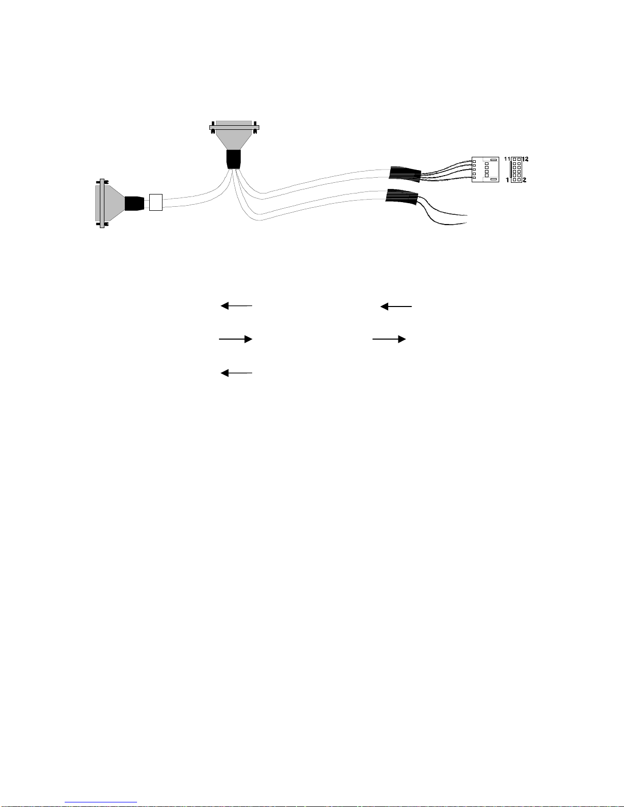
Remote I/O Cable Hookup Instructions
8.5
Archon to Tekmar LSC 2000 / 3000 with HP 5890 w/5970/71/72
MSD and UnixB or MS-DOS Software, and HP 5890/5989 MS Engine, P/N DY-505874-00
Male
Female
Pin Outs
Remote I/O
Archon Color Tekmar Function Color
IN OUT
Desorb
Drain
15
2
Green 24 3 GC Ready Green 6
Brown 23 4 GC Ready White 5
HP
5890
Start
Purge518
P&T
Ready141
The DIP switch UO12 settings in the LSC 2000 must be as follows; 3 OPEN and 4
Note:
Red 1 21 Start Purge Red 1
White 2 22 Start Purge Black 2
Blue 16 21 Start Red To
Black 15 22 Start Black Data System
CLOSED. All others CLOSED. DIP switch UO13, 5 closed all others OPEN.
For a 3000 installation, the Tekmar GC Port must be specified.
1. At the Standby Screen, press the key labeled “CONF.”
2. At the Configuration Screen, press A (GC I/O Port). The GC Port Screen appears.
3. Choose User GC Type=31 Handshaking: ON. Press ENTER to save the selection.
4. Turn the instrument off.
The Tekmar 3000 must be programmed to give a switch closure at purge ready. This switch
closure will initiate the Archon to begin the sample Cycle. Select method 14 to provide correct
polarity settings for the purge ready output. If another method is selected please refer to the
Tekmar manual for additional information.
Connect the cable to the Archon and to the purge and trap.
secure the connector to the chassis.
The 12-position connector will connect to the HP 5890
Be certain the locking screws
and the red and black to the Data System. Refer to your GC and Data System manuals for
correct connector locations.
Note: HP5890 w/5972 needs special box and cable:
1. Parallel REM remote PCA 05990-60320
2. Parallel cable 05990-60019.
03-914642-00:6
8-9
Page 95
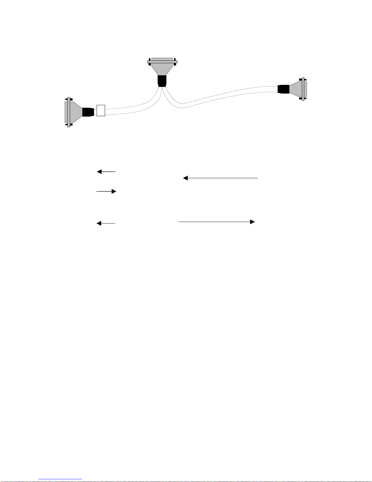
8.6
Archon to Tekmar LSC 2000 / 3000 to HP 6890, P/N DY-505873-00
Male
Female
Pin Outs
Remote I/O
Archon Color Tekmar Function Color
IN OUT
Desorb
Drain
Start
Purge518
P&T
Ready141
15
2
Green 24 GC Ready
Brown 23 4 GC Ready White 7 7 - Ready
Red 1 1,17,19 Start
Purge
White 2 20 Start
Purge
Blue
Black
16
15
21
22
Start Black 1
Male
HP
6890
Red 1 1 - GC
Green 6,9 3 - Start
3
M/S
If you are installing to a 2000 set the DIP switches as follows:
Note:
The DIP switch UO12 settings in the LSC 2000 must be as follows; 3 OPEN and 4
CLOSED. All others CLOSED. DIP switch UO13 all OPEN.
For a 3000 installation, the Tekmar GC Port must be specified.
1. At the Standby Screen, press the key labeled “CONF.”
2. At the Configuration Screen, press A (GC I/O Port). The GC Port Screen appears.
3. Choose User GC-31. Press ENTER to save the selection.
4. Turn the instrument off.
The Tekmar 3000 must be programmed to give a switch closure at purge ready. This switch
closure will initiate the Archon to begin the sample Cycle. Select method 14 to provide correct
polarity settings for the purge ready output. If another method is selected please refer to the
Tekmar manual for additional information.
Connect the cable to the Archon and to the purge and trap
secure the connector to the chassis.
The 9-position “D” connector will connect to either of the
. Be certain the locking screws
HP 6890 APG (Analytical Product Group) remote connectors. These c onnectors are located near
the MIO INET card on the rear of the GC.
8-10
Page 96

Remote I/O Cable Hookup Instructions
8.7
Archon to OI 4460/4560 with HP 5890, P/N DY-505871-00
Female
Pin Outs
Remote I/O Archon
Desorb
Drain
15
2
Color
Green
Brown
Relay I/O
OI Function Color
Terminal
5 GC Ready Red 1
4 GC Ready Black 2
Red
White
Black
HP
5890
Start
Purge 18
P&T
Ready 1
5
14
Attach the “D” connector of the cable to the Ar chon.
Red 7
White 8
6 GC Start Green 5
7 GC Start White 9
Blue 1
Black 2
5 Start Red To
Start White Data
4 Start Black System
Be certain the locking screws secure the
connector to the chassis.
Attach the 12-position connector to the HP 5890.
Attach the individual wires to the Relay I/O terminal at the rear panel of the OI concentrator.
The remaining cable can be used to start the data system.
Refer to the above schematic for the correct wiring locations and to your GC and Data System
manuals for correct connector locations.
Note: 4460A
Archon Color OI
15 Green 4
3Brown5
Dip Switches
03-914642-00:6
1 on (closed)
6 on (closed)
7 on (closed)
8-11
Page 97

8.8
Archon to OI 4460 / 4560 with Varian 3400/3600, P/N DY-505870-00
Female
Pin Outs
Remote I/O Archon
Desorb
Drain
15
2
Color
Green 5 Start Purge Red 3
Brown 4 Start Purge Black 4
Relay I/O
OI
Terminal
Function Color
P23
P16
Red
White
Black
J16-J23
Varian
Motherboard
P16
Start
Purge
P&T
Ready
5
18
14
1
Attach the “D” connector of the cable to the Ar chon.
Red 7
White 8
Blue 1
Black 2
P23
6 GC Starat Green 3
7 GC Start White 1
5 Start Red
Start White
4 Start Black
Be certain the locking screws secure the
connector to the chassis.
Attach connectors P16 and P23 to the Varian GC (J16 and J 23 on the Motherboard) and secure
the grounding clamp to the GC chassis.
Attach the individual wires to the Relay I/O terminal at the rear panel of the OI concentrator.
The remaining cable can be used to start the data system.
Refer to the above schematic for the correct wiring locations and to your GC and Data System
manuals for correct connector locations.
8-12
Page 98

Remote I/O Cable Hookup Instructions
8.9
Archon to OI 4460 / 4560 to HP 5890, RTE HP 1000 GC / MS Software
HP 5970 MSD or HP 5988 MS, P/N DY-505875-00
Female
Pin Outs
Remote I/O Archon
Desorb
Drain
15
2
Color
Green 5 Start
Brown 4 Start
Relay I/O
OI Function Color
Terminal
Red 1
Purge
Black 2
Purge
HP
5890
Red
White
Black
Start
Purge
P&T
Ready
5
18
14
1
Attach the “D” connector of the cable to the Ar chon.
Red 7
White 8
6 GC Ready Green 6
7 GC Ready White 5
Blue 1
Black 2
5 Start Red
White
4Black
4 Start Shield
5 Start Center
Be certain the locking screws secure the
connector to the chassis.
Attach the 12-position connector to the HP 5890.
The remaining cable can be used to start the data system.
Attach the BNC connector to the start box on the GC/MS.
Refer to the above schematic for the correct wiring locations and to your GC and Data System
manuals for correct connector locations.
03-914642-00:6
8-13
Page 99

8.10
Archon to Tekmar 2000/3000 with Varian 3800, PN 03-925673-01
Male
Female
Pin Outs
Remote I/O
Archon Color Tekmar Color 3800
IN OUT
Desorb/
Drain 2
Start
Purge 18
P&T
Ready
Signal
The DIP switch UO12 settings in the LSC 2000 must be as follows; 3 OPEN and 4
Note:
15
5
14
1
Green 24 3 Brown 17 RDY out
Brown 23 4 Orange 16 RDY out
Red 1 21 Black 22 GND
White 2 22 Red 15 Start In
Blue 16
Black 15
CLOSED. All others closed. DIP switch UO13 all OPEN.
Male
For a 3000 installation, the Tekmar GC Port must be specified.
1. At the Standby Screen, press the key labeled “CONF.”
2. At the Configuration Screen, press A (GC I/O Port). The GC Port Screen appears.
3. Choose Standard. Press ENTER to save the selection.
4. Turn the instrument off.
The Tekmar 3000 must be programmed to give a switch closure at purge ready. This switch
closure will initiate the Archon to begin the sample Cycle. Select method 14 to provide correct
polarity settings for the purge ready output. If another method is selected please refer to the
Tekmar manual for additional information.
Connect the cable to the Archon, to the purge and trap, and 3800.
screws secure the connector to the chassis.
Refer to your GC and Data System manuals for
Be certain the locking
correct connector locations.
8-14
Page 100
9 Error Code Screen Messages
Message Description
Must Calibrate (Target
Position) first.
Vial 1 position
Water Probe
Equilibrium Block
Knockoff Clearance
Press any key to reset.
This message appears if one of the Calibrations has
not been performed. Refer to Section 6.
First vial > last in method #.
Press any key to continue.
Vial # type is different in
method # and method #.
Press any key to continue.
Position out of range. Try
again.
Press any key to continue.
Could not sense vial.
Press any key to continue.
Can't Front Park while running.
Press any key to continue
Can't calibrate while running.
Press any key to continue
Can't diagnose while running.
Press any key to continue
Can't control standard while
running.
Press any key to reset.
This message appears if the First vial parameter in the
method number shown, is larger than the Last vial #'s
parameter. Edit the method and change the vial
number entries.
This message shows there are duplicate sample type
settings for the indicated vial two or more methods.
Current settings are greater than 1/4" from previous
settings.
This message occurs if the vial sensor switch does not
detect a vial. The sensor could be damaged or the
vertical coordinate setting could be incorrect. See
Section 6.
This message displays if the Front Park command is
attempted while the instrument is running.
This message displays if Calibration Setup was
attempted while the instrument is running.
This message displays if any of the System
Diagnostics was attempted while the instrument is
running.
This message displays if the Control Standard was
attempted while the instrument is running.
Door Ajar
Resuming
(Front/Rear) Motor timed out.
Left/Right
Vertical
Press any key to reset.
03-914642-00:6
This indicates the sample tray door is open. The door
must be closed while the Robotic Arm is moving.
After the sample tray door is closed, the display will
indicate Resuming.
This message indicates one of the four motors has not
reached its intended position within a set time, or there
is a mechanical blockage, belt slippage, or a loose
Allen set screw.
9-1
 Loading...