

Varian 380-LC, 385-LC Service Manual

Service Manual
FOR
Varian 380-LC & 385-LC
EVAPORATIVE
LIGHT-SCATTERING
DETECTOR
Version 1.0 January 2008
PL0890-0360
Polymer Laboratories Ltd, Now a part of Varian, Inc., Essex Road, Church Stretton,
Shropshire SY6 6AX, UK
Tel +44 (0)1694 723581, Fax +44 (0)1694 722171, Service Tel +44 (0)1694 724333
Polymer Laboratories, Varian, Inc., Amherst Fields Research Park, 160 Old Farm Road,
Amherst, MA 01002, USA Tel +1 413 253 9554, Fax +1 413 253 2476
Polymer Laboratories, Varian B.V., Herculesweg 8, 4339 PL Middelburg,
The Netherlands Tel +31 (0)118 671500, Fax +31 (0)118 671502
Polymer Laboratories, Varian Belgium NV SA, Mechelsesteenweg 362,
2860 St.-Katelijne-Waver, Belgium Tel +32 (0) 15 556460, Fax +32 (0) 15 556186
Polymer Laboratories, Varian Deutschland GmbH, Alsfelder Straße 6,
D-64289 Darmstadt, Germany Tel: +49 (0)6151 7030 Fax: +49 (0)6151 703237
Varian S.A.,7 Avenue des Tropiques, Z.A. Courtaboeuf, B.P. 12
F-91941 Les Ulis Cedex, France Tel +33 1.6986.3838 Fax: +33 1.6928.2308

Document Revision History (6/27401)
Revision # Date Section
Changed
Changes Approval
Draft 24th Jan 2008 All Originated SMB
DO NOT ISSUE THIS PAGE

CONTENTS
INTRODUCTION................................................................................................................... ........................................1
SAFETY ........................................................................................................................................................................2
INSTALLATION............................................................................................................................................................3
Site Preparation Check List........................................................................................................................................3
Unpacking the detector...............................................................................................................................................4
Packing list...................................................................................................................................................................4
Power Connections.....................................................................................................................................................4
Gas Connection...........................................................................................................................................................4
Fluid Connection.........................................................................................................................................................5
Extraction.....................................................................................................................................................................5
Data Connection..........................................................................................................................................................5
Analogue Signal Connector....................................................................................................................................... 5
Serial RS232 Connector............................................................................................................................................5
Connection to a Varian Star 800 Module Interface Box ............................................................................................6
Control I/O connector ................................................................................................................................................6
Installing the Detector.................................................................................................................................................7
Storing the Instrument................................................................................................................................................8
OPTIMISING DETECTOR PERFORMANCE................................................................................................................9
General Considerations..............................................................................................................................................9
Optimisation Parameters............................................................................................................................................9
Gas Flow ................................................................................................................................................................... 9
Evaporator Temperature ...........................................................................................................................................9
Nebuliser Temperature..............................................................................................................................................9
Optimisation Procedure..............................................................................................................................................9
OVERVIEW OF DETECTOR’S OPERATION MODES...............................................................................................11
Standby Mode............................................................................................................................................................11
Run Mode...................................................................................................................................................................11
TROUBLESHOOTING................................................................................................................................................12

Instrument Error Codes............................................................................................................................................12
General Problems......................................................................................................................................................13
REPAIRING THE VARIAN ELSD...............................................................................................................................14
Overview of Main Assembly.....................................................................................................................................14
Removing The Front Panel .....................................................................................................................................15
Overview of Nebuliser Assembly.............................................................................................................................17
Removing The Nebuliser.........................................................................................................................................18
Installing The Nebuliser........................................................................................................................................... 20
Replacing The Nebuliser Heater Assembly............................................................................................................. 22
Replacing The Nebuliser Chamber .........................................................................................................................24
Replacing The Solvent Leak Assembly................................................................................................................... 26
Replacing The Vapour Sensors ..............................................................................................................................27
Replacing The Fan Assembly .................................................................................................................................30
Overview of Varian 380-LC Evaporator Assembly..................................................................................................32
Removing And Cleaning The Evaporator Cartridge (Diffuser) ................................................................................33
Replacing The Evaporator Heater Assembly (Evaporation Tube)........................................................................... 35
Replacing The Mass Flow Controller ...................................................................................................................... 37
Replacing The Gas Inlet Plug Assembly .................................................................................................................38
Replacing The Gas Inlet Assembly .........................................................................................................................39
Replacing The Nebuliser Gas Regulator................................................................................................................. 41
Overview of Varian 385-LC Evaporator Assembly..................................................................................................43
Removing And Cleaning The Varian 385-LC Evaporator Cartridge (Diffuser) ........................................................44
Replacing The Varian 385-LC Cooled Evaporator Assembly.................................................................................. 46
Overview of Optical Assembly.................................................................................................................................50
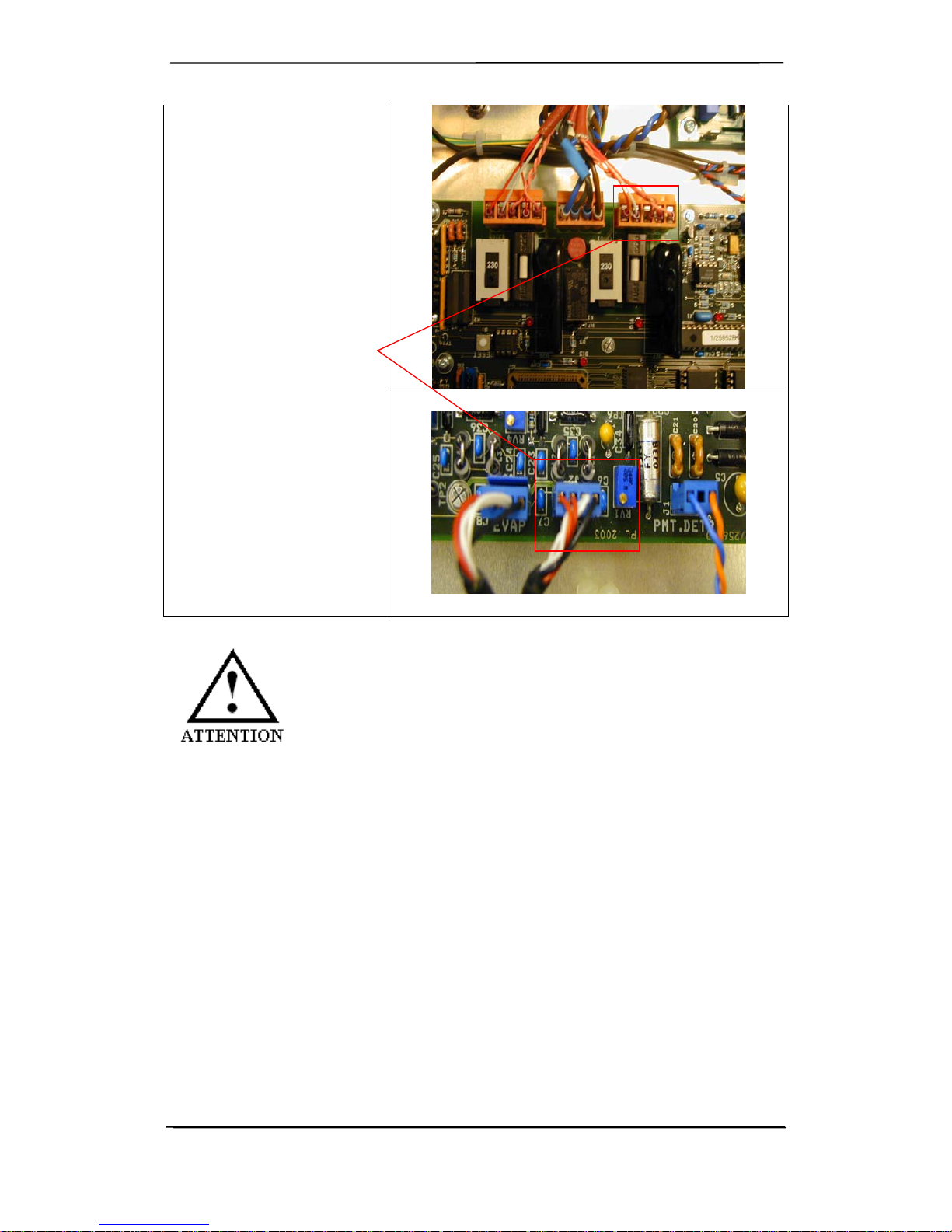
Removing The Photodetector (PMT) Assembly ......................................................................................................51
Adjusting Photodetector (PMT) Sensitivity ..............................................................................................................53
Replacing The LED Light Source Assembly............................................................................................................ 55
Cleaning The Optical Lens Assembly ..................................................................................................................... 57
Replacing The Optical Light Trap............................................................................................................................ 59
Replacing The Optical Heater .................................................................................................................................61
Removing & Cleaning The Prism Assembly............................................................................................................62
Electronics.................................................................................................................................................................64
Replacing The Main Control PCB ...........................................................................................................................64
Replacing The Power Supply ..................................................................................................................................66
Firmware.....................................................................................................................................................................69
Device Identifier ...................................................................................................................................................... 70
Upgrading Firmware................................................................................................................................................ 71
Programming Device Identity ..................................................................................................................................76
IDENTIFYING PARTS AND MATERIALS..................................................................................................................80
INSTRUMENT SPECIFICATIONS...................................................................................................... ........................82
CLEANING & DECONTAMINATION PROCEDURES................................................................................................83
Cleaning .................................................................................................................................................................. 83
Decontamination .....................................................................................................................................................83
#6/27401 1
Varian ELSD Service Manual
INTRODUCTION
The combined Varian ELSD Service Manual is designed for use by personnel who have had training and are
experienced in servicing this type of equipment. Whilst the ELSD has been designed for easy repair, there are
potential hazards associated with servicing this instrument. We strongly recommend that our service engineers
perform all servicing
It is understood that the purchaser must assume all risk in the use of this manual for the purpose of performing
service upon the instrument it covers. There are no user-serviceable parts in the Varian ELSD
Varian, Polymer Laboratories strongly recommends the use of original Varian spare parts only, otherwise we do not
guarantee any specification or liability
It is strongly recommended that the operator read the entire manual carefully before attempting to service the
instrument. In addition, be sure to observe all signs and pictographs that are specifically defined as follows:
WARNING:
The “warning sign” denotes a hazard. It calls attention to a procedure,
practice which, if not correctly done or adhered to, could result in severe
injury or damage or destruction of the instrument. Please do not proceed
beyond a warning sign until the indicated conditions are fully understood
and met.
ATTENTION:
The “attention sign” denotes relevant information. Read this information
first before proceeding, it will be helpful or necessary to complete the
task.
NOTE:
The “note sign” denotes additional information.
It provides the user with advice and suggestions to facilitate the
operation of the instrument
#6/27401 2
Varian ELSD Service Manual
SAFETY
The following procedures require opening the main cover of the detector. Always ensure
that the detector is disconnected from the mains power when the side panel is opened. The
Varian ELSDhas a safety bar at the power input socket that prevents the detector’s side
panel being opened when the power cable is still connected.
WARNIN
To disconnect the detector from the mains supply line, unplug the power cord. When
working with solvents please observe appropriate safety procedures (for example, safety
goggles, gloves and protective clothing), especially when toxic or hazardous solvents are
used.
NOTE AUTION
Electronic boards and components are sensitive to electronic discharge (ESD). In order to
prevent damage always use ESD protection when handling electronic boards and
components.
WARNING
The LED light source is a Class 1 LED product. Temporary discomfort may result from
directly viewing the light produced by this source. Do not look into the beam.
Make sure that only fuses with the required rated current and of the specified type (superfast, fast, time delay etc) are used for replacement. The use of repaired fuses and the shortcircuiting of fuse-holders must be avoided.
Any adjustment, maintenance, and repair of the opened instrument under voltage should be
avoided as much as possible. When inevitable, this should only be carried out by a skilled
person who is aware of the hazards involved.
Use of a mains isolating transformer is recommended.
Read and understand the Varian ELSD user manual before undertaking any service
operations on this instrument.
#6/27401 3
Varian ELSD Service Manual
INSTALLATION
Site Preparation Check List
Environmental Conditions
Temperature 15° to 35°C (59 to 86°F)
At constant temperature
Avoid positioning in direct sunlight
Humidity 10-80%
Power
USA and Japan 115V (AC) ±10%
50/60 Hz, 2A max, with a protective earth connection.
Europe 230V (AC) ±10%
50/60 Hz, 2A max, with a protective earth connection.
Gas Supply
Gas: Nitrogen (98% purity or better and filtered to 0.2µm)
Notes:
⇒ Air can only be used for non flammable solvents
⇒ The mass flow controller is not calibrated for use with
gases other than Air or Nitrogen
⇒ For operation with other inert gases contact Polymer
Laboratories for advice.
Gas flow: up to 3.25 SLM @ 60 psi @ 25°C
Pressure operating range: 60 – 100 psi (4-6.7 bar)
Maximum Pressure: 100 psi (6.7 bar)
Extraction Requirements
During normal operation the carrier solvent is evaporated as it passes
through the instrument and must be extracted safely at the rear of the unit.
The exhaust from the instrument (13mm ID PVC tubing) must be extracted to a fume hood or similar
solvent disposal unit. If the extraction tube provided with the instrument is to be extended it is
recommended that the diameter of the extension is increased to at least 50mm (2”) diameter tubing so the
extraction quality is not inhibited.

#6/27401 4
Varian ELSD Service Manual
Unpacking the detector
Care has been taken to ensure that the instrument should be received in proper condition. The packing and
protection are designed for normal hazards of road, rail or air transit. Any damage to the container or instrument
should be reported immediately to your local distributor, or to Varian. It is recommended that the shipping container
be kept, if possible, for re-shipment or return to a service centre.
Examine the shipping carton for visible signs of exterior damage. Unpack the instrument and examine it for transit
damage. Check that all items on the packing list are included.
Notify your local distributor or Polymer Laboratories, Varian of any damage or missing items.
Packing list
• Varian ELS Detector
• Operation Manual
• Control Software[SMB1]
• Mains leads (UK, EUR, USA)
• RS232 data cable
• Analogue output Cable
• Gas Tubing (2m)
• PVC Exhaust hose (2m)
• Tygon SE200 waste hose (7cm)
• 500ml Solvent waste container
Power Connections
• Before connecting the power cable, ensure the instrument voltage rating matches your local power supply.
• Use only a supply with protective grounding.
• The correct fuses should be installed.
• For 115V (AC) or 230V (AC) use two 250V H 2A T fuses
THIS UNIT IS DOUBLE - FUSED.
RISK OF FIRE, REPLACE FUSES AS MARKED!
If the voltage rating and fuses are correct for your power source, connect the power cable
Gas Connection
The instrument should be supplied with clean, dry nitrogen gas at a minimum head pressure of 60psi. A 4mm pushin connector is provided at the rear of the instrument for a convenient connection to the gas source.
To prevent against unnecessary gas usage, an automatic but controlled gas shut off valve is integrated into the gas
inlet manifold. This will only allow gas to pass into the instrument when the instrument is operating. Should the
instrument default to a standby mode the gas valve will close after 15 minutes.

#6/27401 5
Varian ELSD Service Manual
THE GAS INLET VALVE WILL BE CLOSED WHEN THE INSTRUMENT IS FIRST
POWERED ON AND WILL ONLY OPEN ONCE THE INSTRUMENT IS SET TO
RUN MODE
Fluid Connection
The eluent from the chromatography system is connected to the front of the instrument via the low dead volume
Valco bulkhead connector provided.
USE ONLY VALCO FITTINGS
The liquid inlet port is connected directly to the nebuliser by a short length (130mm) of capillary tube giving a delay
volume from port to nebuliser tip of ~5µl.
Extraction
The Varian ELSD is provided with tubing for venting the exhaust gases and vapors, and so does not need to be
placed in a fume cupboard. Instead, the exhaust hose provided must be attached to the rear of the unit and vented to
a fume hood or other disposal unit. Ensure the exhaust hose has an upward slope from the Varian ELSD so that any
condensed solvent is collected in the waste bottle at the front of the unit and to prevent it accumulating in the tubing.
THE EXHAUST MUST BE EXTRACTED TO A SUITABLE FUME EXTRACTION
SYSTEM
Data Connection
Analogue Signal Connector
The Varian ELS detector is supplied with a 1V analogue output cable (PL0890-0300) that allows data collection via
an A/D interface, such as a Star MIB 800 module. The gold end fitting of the analogue cable plugs into the gold pin
on the rear of the detector and the opposite end connects to the positive and negative inputs of the A/D interface.
Serial RS232 Connector
The Varian ELS detector is fitted with a standard RS232 (DTE-DCE) 3-wire serial interface.
The serial RS232 connector provides a 24bit (10 or 40Hz) digital output for connection to a PC running a data
acquisition package (e.g. Galaxie Chromatography software.
If controlling the instrument from a PC, a free serial port is required. A USB port on the PC can be used but a USBto-Serial adapter is required (PL0860-0620).
The Varian ELS detector is also fitted with a service connector, located below the RS232 port, for flash upgrading
firmware (see pg 71)

#6/27401 6
Varian ELSD Service Manual
Connection to a Varian Star 800 Module Interface Box
The Star 800 Module Interface Box (MIB) provides analogue-to-digital signal conversion (ADC). Connections are
made by connecting the analogue output cable to one of the analogue signal input ports on the middle right side of
the Star 800 MIB. For more information about connecting your Varian ELS detector to a Star 800 MIB, refer to your
Star 800 MIB documentation.
Control I/O connector
The Varian ELS detector can be connected to auxiliary equipment, such as an autosampler, or pump via the 15pin
I/O connector. The I/O connector can be configured in several ways to allow on-board timetable events to be
triggered or to remotely auto-zero and shutdown the detector.
The ELS detector is equipped with 2 contact closures (normally-open) for stopping the operation of a pump if the unit
reports an error condition.
The Varian ELS detector is also equipped with one contact closure, which is normally open, and two TTL logic inputs,
both active-low (with internal pull-up resistors to 5 V).
Pump stop facility must be employed if the instrument is to be left unattended,
or if units are stacked.
I/O description Pin number
Inputs Remote Start 14 & ground
Remote Standby 13 & ground
Remote A/Z 7 & ground
Output Pump stop contact closure – normally open 3 & 10
Ground (to case) 1, 5, 6, 11
Varian ELS detector I/O connections
The instrument is not supplied with a 15 pin I/O cable for the I/O socket or remote start cable. For remote start
operation, and I/O connections additional cables are required and can be purchased from Varian Inc (Remote start
cable Part # PL0890-0350, I/O Cable PL0890-0345).

#6/27401 7
Varian ELSD Service Manual
Installing the Detector
Connect the power cord to the IEC inlet at the rear of the unit.
• Check the operating voltage of your instrument, 110V 2A or 230V 2A, on the IEC inlet fuse-holder on rear
of unit.
• Attach the gas inlet tube to the gas inlet at the back of the instrument.
• The gas connection is a 4mm OD push-in fitting. The nitrogen gas should be dry, filtered and have a
minimum inlet pressure of 60psi, 60-100psi is required to achieve the maximum operating instrument gas flow
rate of 3.25 SLM throughout the temperature range.
• Connect the waste tube to the waste outlet at the front of the detector and position the other end in a waste
collection bottle.
• The solvent waste container supplied with the detector can be sited on the bench in front of the instrument.
Alternative waste collection vessels can be used if required but the bottom of the waste tube must be below the
height of the waste outlet from the instrument. The waste tube must NOT be submerged in the liquid.
• Connect the exhaust hose between the exhaust outlet and a fume hood.
• Connect the instrument to the data recorder (computer, chart recorder, etc.) using the cable provided. One
output socket is provided giving a signal in the 0-1V range.
• Connect the column outlet to the eluent inlet at the front of the unit) using a short length (10cm) of tubing
(1/16” OD, 0.010” ID) and a 1/16” Valco fitting.
• Turn on the source gas to a pressure of about 60-100 psi. The gas will not flow though the detector until
the instrument in set to RUN mode.
• Switch on the ELSD and select method “XXX”.
• Start heating by selecting RUN mode using the arrow keys on the front keypad.
• When the unit has equilibrated, the baseline should be checked to ensure that it is acceptable for the
experiment. At this point, with no liquid flowing into the instrument, the noise should be no more than 0.3mV
peak-peak. This verifies that the gas supply is clean and dry. Any spikes in the baseline are usually indicative
of particulate matter or water in the gas supply.
• Turn on the eluent flow and allow the system to stabilize for approximately 15 minutes.
THE ELUENT FLOW CAN BE TURNED ON BEFORE THE INSTRUMENT HAS
REACHED EQUILIBRIUM. IF THE ELUENT IS NOT EFFICIENTLY NEBULISED IT WILL
EXIT THE INSTRUMENT FROM THE NEBULISER DRAIN TUBE.
• Again check the baseline noise as it should not have increased significantly. and should be <1mV.
Typically the baseline noise is 0.3mV peak-peak.
If the baseline noise is excessive, then one of the following may be taking place: -
• poor evaporation due to gas flow being too low
• poor evaporation due to evaporation temperature being too low
• poor nebulisation due to temperature being too high and solvent boiling
Any of these problems will cause the baseline to shift upwards, as the amount of scattered light within the instrument
has increased. If the baseline continues to show unacceptable noise even when the evaporation conditions have

#6/27401 8
Varian ELSD Service Manual
been improved, and the solvent does not contain non-volatile species, then please refer to Chapter 5
Troubleshooting.
Where noise and all other conditions are acceptable, the instrument is ready to begin work.
NON-VOLATILE BUFFERS ARE NOT COMPATIBLE WITH THE ELSD
Storing the Instrument
If the instrument is to be stored or not used for a period of time it is recommended to follow the procedure outlined
below:-
• Allow the instrument to cool to ambient temperature in STANDBY mode with the gas supply still connected.
• Tip the instrument forwards and empty the 'P' trap contents through the front waste tube (i.e. into the bottle)
• Pour 10 to 20mls of acetone into the exhaust tube to flush out the P trap, collecting the waste in the waste
bottle at the front of the instrument.
• Again tip the instrument forwards to drain the p-trap
• Disconnect the waste bottle
• Using the gas supply, blow nitrogen gas through the exhaust to evaporate any remaining acetone in the p-
trap. Cover the waste tube with tissue paper to collect any acetone residue.
• Plug the exhaust and waste tubes with the plastic caps provided.
• Plug the solvent inlet.

#6/27401 9
Varian ELSD Service Manual
OPTIMISING DETECTOR PERFORMANCE
General Considerations
The Varian ELSD instrument should be thought of as a detector like any other designed for liquid chromatography.
The main distinguishing feature is the ability to evaporate the solvent from the column eluent. Therefore, normal
system set-up precautions should be remembered when starting to use the instrument. Any solvent intended for use
with the ELSD should be fully miscible with any previously used in the liquid chromatograph; if there is any
uncertainty, a mutually miscible solvent should be run through the system as an intermediate liquid. The sample loop
should also be flushed with miscible solvent where necessary. The intended eluent should be thoroughly degassed,
contain no
non-volatile salts or material and should be fully compatible with the column(s). All connections should be
made with zero dead volume fittings and tubing with an I.D. <0.010”.
The Varian ELSD requires nitrogen (purity >98%), capable of generating 60-100psi inlet pressure. If in-house
nitrogen is not available then we recommend the use of a nitrogen generator, giving a constant uninterrupted supply
of high purity gas. Air can be used with non-flammable solvent systems. The eluent of choice should be fully volatile
under the chosen detector parameters – any non-volatilised eluent will increase baseline noise and reduce
sensitivity.
Optimisation Parameters
Gas Flow
An increase in gas flow rate causes a decrease in signal response. Lower gas flow rates are more favourable since
less gas is consumed and a better sensitivity is achieved. However, there comes a point at which this benefit is
counterbalanced by the increase in baseline noise due to inefficient evaporation of the eluent. In general, gas flow
rates of 1.0-2.0SLM tend to be a reasonable compromise between baseline stability and high reproducible response
for eluent flow rates >0.5ml/min. Reducing the eluent flow allows a reduction in the gas flow rate to maintain the
optimum particle stream concentration, resulting in greater sensitivity.
When operating the Varian 385-LC at sub-ambient temperatures in aqueous solvents, gas flow values of >2.0SLMs
maybe necessary to control the baseline noise.
Evaporator Temperature
The effects of altering the evaporator temperature tend to be less dramatic than changing the gas flow, although the
temperature must be high enough to evaporate the solvent and to sufficiently dry the particle plume without having a
detrimental effect on the sample being studied.
The Varian ELSD can be operated at sub-ambient temperatures to improve the detection of semi-volatile
compounds. In aqueous solvents, baseline noise may become too excessive at temperatures <15°C. However, for
organic solvents, the baseline can be controlled down to 10°C, provided the gas flow is increased to compensate
.
Nebuliser Temperature
The nebuliser temperature is the parameter requiring least adjustment. In the majority of cases the nebuliser
temperature is set to the temperature of the chromatography system. However, increasing this temperature can
improve instrument performance by increasing the efficiency of nebulisation by reducing the viscosity and surface
tension of incoming solvent. Setting the nebuliser temperature too high may result in a deterioration of detector
performance due to solvent boiling in the nebuliser, giving rise to increased noise on the baseline due to spiking
Optimisation Procedure
Set the system at the minimum evaporator and nebuliser temperatures and a gas flow rate of 1.6 SLM. Make an
initial injection of the test component and monitor the signal response. With each subsequent injection increase the

#6/27401 10
Varian ELSD Service Manual
nebuliser and evaporator temperatures by 10°C whilst reducing the gas flow rate, until optimum sensitivity is
achieved. In some cases, especially for volatile samples, it has been found that maximizing the nebuliser
temperature permits a lower evaporator temperature and thus an increase in sensitivity

#6/27401 11
Varian ELSD Service Manual
OVERVIEW OF DETECTOR’S OPERATION MODES
The Varian ELSD can be operated in two modes; STANDBY and RUN as described below:
To display the current mode and/or select a new mode, highlight the MODE function on the instrument display. The
current mode will now be displayed on the screen. Using the ▲▼ keys, scroll up or down until the desired option is
displayed. The instrument acknowledges the command by displaying the mode of operation in the top right hand
corner of the screen.
Standby Mode
The STANDBY mode is the “ground state” of the Varian ELSD instrument, which is initiated automatically after power
on. In this mode of operation the heaters are off, and the gas manifold valve is closed. The STANDBY mode
enables the user to set-up the operational parameters (gas flow, nebuliser and evaporator temperatures) before
switching the unit into RUN mode. The instrument will default to STANDBY mode should an error occur on the
instrument
When the instrument is switched from RUN mode to STANDBY mode, following a command or error then the gas
flow is set to a minimum flow of 1.2SLM for 15minutes before the gas manifold valve is closed. This minimum
“blanket” gas is enough to nebuliser and evacuate solvent should the instrument default to STANDBY mode with
solvent still flowing [firmware 1.1.8 or later].
If the Instrument is left in STANDBY mode for longer than 15mintes, gas flow
to the unit is stopped to minimize gas usage.
It is strongly recommend that the pump stop from the I/O connector of the
Varian ELSD is connected to the HPLC pump to prevent solvent flooding of
the detector should an error occur
Run Mode
The RUN mode is the detector’s normal operational mode. In this mode, the instrument controlled at the set
temperatures and gas flow, and the system is fully operational. During heating or cooling the instrument will display
‘NOT READY’ to show the system has not
reached the set conditions. When the instrument has reached the set conditions and equilibrated, ‘READY’ will be
displayed and the instrument is ready for use.
USING THE INSTRUMENT IN ‘NOT READY’ STATUS MAY NOT PRODUCE
CONSISTENT RESULTS ACCORDING TO THE SET PARAMETERS, AS THE
SYSTEM IS NOT EQUILIBRATED.

#6/27401 12
Varian ELSD Service Manual
TROUBLESHOOTING
If a problem is encountered Polymer Laboratories advises a system test be performed via the Varian ELSDPC
control software to ensure that the detector is working correctly. If there is an error or fault, please refer to the
following table. If you follow the recommended course of action and the result is not satisfactory, then please direct
the matter to Polymer Laboratories or your local distributor.
Instrument Error Codes
Error Code Description Suggestions
10 Air Temp <= 10°C Inside Enclosure Environmental Temp Too Cold
11 Air Temp > 40°C Temp Inside Enclosure Environmental Temp Too Hot
12 On-Board Sensor Heater Failed Vapour Sensor Needs Replacing (see
page 27)
13 Rear Panel Sensor Heater Failed Vapour Sensor Needs Replacing (see
page 27)
14 Leak Detected Inside Unit Solvent Vapour Detected.
Stop Pump
15 Liquid Leak Sensor Has Detected Liquid In
Drip Tray
Liquid In The Base Of The Unit- Stop
Pump And Investigate
16 Fan Driver IC Thermal Shutdown Fault With The Circuitry / Wires / Fan
17 Fan Stopped Fault With The Circuitry / Wires / Fan
(see page 30)
18 Nebuliser Temperature Exceeded Threshold
After Stabilizing
Faulty Thermocouple Or Heater
Control
19 Evaporator Temperature Exceeded Threshold
After Stabilizing
Faulty Thermocouple Or Heater
Control
20 Light Source Error Replace Light Source Assembly (see
page 38)
21 Evaporator Gas Flow Rate Exceeded
Threshold After Stabilizing
Check Operating Head Pressure,
Otherwise Faulty Mass Flow
Controller
(see page 37)
22 Invalid Nebuliser Temp Reading (FAULTY
RTD)
Replace Nebuliser Heater Assembly
(see page 22)
23 Invalid Evaporator Temp Reading (FAULTY
RTD)
Replace Evaporator Assembly (see
page 32)
24 Fan failure on cooled evaporator Replace Cooled Evaporator Assembly
(see page 43)
25 Bridge current outside of normal range Replace Cooled Evaporator Assembly
(see page 43)

#6/27401 13
Varian ELSD Service Manual
General Problems
Fault/Problems Possible Cause(s) Remedy
Baseline noise The particle plume is not sufficiently dried
in the evaporator tube.
• Increase the temperature of the
evaporator by 10° intervals until the
noise is acceptable
Baseline noise Poor nebulisation of solvent • Increase the gas flow rate
• Decrease the nebulisation
temperature
Baseline noise Pump pulsations, especially in microbore
applications where low flow rates are used.
• Use a pulse free pump
• Increase the back pressure on the
pump by fitting a back pressure
regulator between the pump and the
injection valve.
• Use a pulse dampener directly
after the pump in the system.
Baseline spikes 1. Particulate matter in the gas supply
2. Column shedding
3. Poor nebulisation
• Filter the incoming gas, or change
the supply
• Replace column or fit an inline filter
with a 0.2µm membrane filter directly
after the column.
• Nebuliser temperature may be too
high and solvent may be boiling; reduce
nebuliser temperature
Low sensitivity and
baseline noise
Diffuser saturated with solvent • Stop the eluent flow and increase
the evaporator temperature to 50°C
above the current set temperature.
Increase the flow rate to 2.8SLM and
wait 15mins.
Large Baseline offset 1. Inefficient evaporation
2. High concentration of non-volatile
buffer or stabiliser
3. Contaminated diffuser
• Increase the evaporator
temperature and/or gas flow.
• Use a lower concentration of
stabiliser, unstabilised solvent or a more
volatile buffer
• Perform ‘steam clean’. (Section
4.2 Operation’s manual)
Peak tailing Eluent particles lingering in the optical
chamber
• Increase gas flow rate
Instrument Fails to zero Offset too high or output unstable • Ensure the instrument is in RUN
mode
• Refer to local distributor or
Polymer Laboratories
No power
1. Mains lead not connected
2. Fuse failure
• Attach mains lead to socket and
inlet on rear of instrument
• Replace fuse
No response (completely
flat baseline)
1. Data acquisition leads not connected
2. Light source inactive
3. Instrument in STANDBY mode
• Ensure connectors to computer or
integrator are sound
• Check LED
• Select RUN mode
Temperature error as soon
as instrument powered on
Temperature probe fault or disconnected • Check RTD connections
Display not on, but power
connected, blue glow ON.
Instrument in service mode • Rear panel switch-set to RUN
#6/27401
14
Varian ELSD Service Manual
REPAIRING THE VARIAN ELSD
Overview of Main Assembly
To allow easy access to the internal components of the Varian ELSD, the left-side panel folds outwards. The lock is located at the rear of the instrument, which
can be opened using the access key (part # 0890-0440)
See page 56
See page xx
See page xx
See page 67
See page 33 Varian 380-LC
See
pag
e 44 Varian 385-LC

#6/27401 15
Varian ELSD Service Manual
Removing The Front Panel
When required: For majority of internal repairs
Tools required: Allen keys
Varian ELSD Enclosure Access Key (# 0890-0440)
Parts required:
Ensure that the detector is disconnected from the mains power
before proceeding.
To prevent personal injury, the power cable must be removed from
the instrument before opening the detector. Do not connect the
power cable to the detector while the covers are removed.
Use the Access key to open
the lock located at the rear
of the instrument. Fold
down the left-side panel of
the detector
Disconnect the nebuliser
tubing and cables from the
inside of the front panel.

#6/27401 16
Varian ELSD Service Manual
Remove screws located at
the top and bottom of the
inside side panel, to allow
removal of the front panel.
Remove the front panel by
lifting and pulling
backwards, to release the
four locating screws from
the bulkhead.

#6/27401 17
Varian ELSD Service Manual
Overview of Nebuliser Assembly
The nebuliser assembly is based around a nebuliser chamber (white PTFE block) into which
the nebuliser, drain tubes, gas tubes and evaporation tube are connected. Access to the
nebuliser section requires the removal of the front panel (see page 15)

#6/27401 18
Varian ELSD Service Manual
Removing The Nebuliser
When required: If Nebuliser becomes blocked
Tools required: Allen keys
Spanners
Parts required: ELSD Nebuliser (# 0890-0390)
Ensure that the detector has cooled down before proceeding
Ensure that all gas and solvent connections are disconnected
prior to proceeding
Open the detector and remove the front panel as
described in “Removing the front panel”(pg 15).
Disconnect the nebuliser tubing from the inlet
bulkhead.
Disconnect the gas inlet as highlighted

#6/27401 19
Varian ELSD Service Manual
Loosen the nebuliser mounting plate by loosening
the top screw as highlighted
VERY carefully remove the nebuliser from the
mount as shown
Check the nebuliser for damage or blockages
To install the nebuliser see “installing the nebuliser
section (pg20)
DO NOT PLACE THE NEBULISER IN AN ULTRASONIC BATH
BLOCKAGES MUST BE REMOVED USING A SPECIAL CLEANING TOOL

#6/27401 20
Varian ELSD Service Manual
Installing The Nebuliser
When required: If Nebuliser becomes blocked
Tools required: Allen keys
Spanners
Parts required: ELSD Nebuliser (# 0890-0390)
Ensure that the detector has cooled down before proceeding
Ensure that all gas and solvent connections are disconnected
prior to proceeding
Check that the nebuliser is not damaged before
removing from packaging.
Fit the gas connector and finger-tight connector to
the nebuliser as shown.
Connect the nebuliser to the inlet tubing via the
union connection

#6/27401 21
Varian ELSD Service Manual
Very carefully insert the nebuliser into the
nebuliser mount
Connect the gas tubing to the nebuliser
To check the correct gas flow is being delivered to
the nebuliser, connect a gas flow meter in-line
between the gas regulator (shown), and the
nebuliser.
NOTE: the instrument needs to be switched on
and set to run mode
The correct gas flow to the nebuliser should be
0.40SLM.
If the gas flow is incorrect adjust the gas regulator,
by pulling down the black knob and twisting, until
the correct flow is achieved
Disconnect the in-line flow meter and reconnect
the regulator to the nebuliser.
The IQ/OQ procedure must now be preformed to
ensure the detector is performing as specified
(see PMT section pg 51)
A quality control test must be performed following nebuliser removal, to ensure
detector performance. (Appendices 3 and 4 Varian ELSD Operation Manual)

#6/27401 22
Varian ELSD Service Manual
Replacing The Nebuliser Heater Assembly
When required: Failure of Nebuliser heater
Tools required: Allen keys
Spanners
Parts required: Varian Neb mount assembly (#PL0890-0485)
Ensure that the detector has cooled down before proceeding
Ensure that all gas and solvent connections are disconnected
prior to proceeding
Open the detector and remove the
front panel as described in
“Removing the front panel”(pg 15).
Remove the nebuliser as described
in “Removing the nebuliser”(pg 18).
Disconnect the gas tubing from the
nebuliser mount and Remove the
three mounting screws with an
Allen key as shown.
#6/27401 23
Varian ELSD Service Manual
Disconnect the two Nebuliser
Heater Assembly cables from the
main control board (NEB.HTR &
NEB) and remove the nebuliser
heater assembly.
Ensure that the earthing cable is connected to the nebuliser
heater assembly before switching on the instrument
 Loading...