

Page 1

NOTICE: Varian, Inc. was acquired by Agilent
Technologies in May 2010. This document is provided
as a courtesy but is no longer kept current and thus
will contain historical references to Varian. For more
information, go to www.agilent.com/chem.
Varian, Inc.
2700 Mitchell Drive
Walnut Creek, CA 94598-1675/USA
Saturn® 2000 GC/MS
MS Workstation
Version 6
Operation Manual
©Varian, Inc. 2003-2009 Printed in U.S.A. 03-914979-00:5
Page 2

Page 3

Contents
Getting Started........................................................................................................................11
About this Manual/Help ............................................................................................................................................11
Additional Manuals/Help...........................................................................................................................................11
MS Workstation Toolbar ........................................................................................................13
Overview...................................................................................................................................................................13
Elements of the MS Workstation Toolbar.................................................................................................................14
Launching Applications from the MS Workstation Toolbar
Using the Application Icon Buttons...........................................................................................................................19
Using the Data File and Method Quick Link buttons................................................................................................19
................................................19
MS Workstation Toolbar Options..........................................................................................21
Moving the MS Workstation Toolbar........................................................................................................................21
The MS Workstation Toolbar Options Menu............................................................................................................21
2000 MS Module Control........................................................................................................25
Starting System Control the First Time ....................................................................................................................25
Configuring the Instrument.......................................................................................................................................25
Configuring the 3800 or 3900 GC Communication (No Company Network) ...........................................................32
Configuring the GC for a Company Network............................................................................................................34
Using a Password to Protect BOOTP Settings ........................................................................................................39
Adding a GC and Varian MS to the Instrument in System Control ..........................................................................41
2000 MS Instrument Control Command Reference
Saturn Module Dialogs.............................................................................................................................................47
2000 Module Window...............................................................................................................................................48
2000 MS Instrument Window
The 2000 MS Instrument Window............................................................................................................................59
Status and Control Window......................................................................................................................................73
.................................................................................................59
.............................................................47
3800 GC System Control Window.........................................................................................99
The Instrument Window............................................................................................................................................99
The 3800 GC Status and Control Window.............................................................................................................100
Documenting Module Information ..........................................................................................................................104
3800 GC Injecting a Single Sample.....................................................................................107
Overview.................................................................................................................................................................107
Using the Inject Single Sample Dialog Box............................................................................................................107
Specifying the Data File Name and Path ...............................................................................................................108
1
Page 4

Specifying Per-Sample Data Handling Parameters ...............................................................................................109
Specifying a RecalcList ..........................................................................................................................................110
Monitoring the Status of the Run............................................................................................................................110
Using QuickStart.....................................................................................................................................................111
3800 GC Injecting Multiple Samples ...................................................................................113
Introduction.............................................................................................................................................................113
Using a SampleList in System Control...................................................................................................................113
Specifying the Data File Name and Path ...............................................................................................................115
Specifying Per-Sample Data Handling Parameters ...............................................................................................116
Specifying a RecalcList ..........................................................................................................................................116
Changing Default SampleList Entries.....................................................................................................................117
Reading Vial Positions from an 8200 AutoSampler ...............................................................................................117
Monitoring the Status of Runs................................................................................................................................118
Saving SampleLists for Later Use..........................................................................................................................119
Using More Than One Method for Injections..........................................................................................................119
3900 GC System Control Window.......................................................................................123
The Instrument Window..........................................................................................................................................123
The 3900 GC Status and Control Window.............................................................................................................124
Documenting Module Information ..........................................................................................................................128
3900 GC Injecting a Single Sample.....................................................................................131
Overview.................................................................................................................................................................131
Using the Inject Single Sample Dialog Box............................................................................................................131
Specifying the Data File Name and Path ...............................................................................................................132
Specifying Per-Sample Data Handling Parameters ...............................................................................................132
Specifying a RecalcList ..........................................................................................................................................133
Monitoring the Status of the Run............................................................................................................................133
Using QuickStart.....................................................................................................................................................134
3900 GC Injecting Multiple Samples ...................................................................................137
Introduction.............................................................................................................................................................137
Using a SampleList in System Control...................................................................................................................137
Specifying the Data File Name and Path ...............................................................................................................139
Specifying Per-Sample Data Handling Parameters ...............................................................................................140
Specifying a RecalcList ..........................................................................................................................................140
Changing Default SampleList Entries.....................................................................................................................141
Monitoring the Status of Runs................................................................................................................................141
Saving SampleLists for Later Use..........................................................................................................................142
Using More Than One Method for Injections..........................................................................................................142
System Control Menus.........................................................................................................145
File Menu................................................................................................................................................................145
Edit Menu................................................................................................................................................................146
Inject Menu.............................................................................................................................................................147
Automation Menu....................................................................................................................................................147
Recalculate Menu...................................................................................................................................................148
Instrument Menu.....................................................................................................................................................148
Windows Menu.......................................................................................................................................................149
Help Menu ..............................................................................................................................................................150
2
Page 5

System Control Toolbar.......................................................................................................151
Main Toolbar...........................................................................................................................................................151
2000 MS Method Basic Scan Functions .............................................................................153
Introduction.............................................................................................................................................................153
2000 MS Method Chemical Ionization.................................................................................155
Introduction.............................................................................................................................................................155
The Chemical Ionization Scan Function.................................................................................................................155
Ion Formation By Chemical Ionization....................................................................................................................157
The CI Parameters .................................................................................................................................................158
Chemical Ionization Using Fixed Parameters ........................................................................................................162
Using Liquid CI Reagents.......................................................................................................................................162
Adjusting the CI Reagent Gas Pressure for Gases Other Than Methane.............................................................165
Tuning for CI Operation..........................................................................................................................................166
Low-Pressure CI vs. High Pressure CI...................................................................................................................166
Recommended Reading.........................................................................................................................................167
2000 MS Method Command Reference...............................................................................169
Spreadsheet editing................................................................................................................................................169
The CI Parameters .................................................................................................................................................175
CI Fixed Parameters...............................................................................................................................................176
Ion Storage (SIS) Parameters................................................................................................................................177
Customize SIS........................................................................................................................................................177
The MS/MS Ion Prep Method.................................................................................................................................178
The MS “q” Calculator ............................................................................................................................................178
Ion Preparation MS/MS..........................................................................................................................................183
MSn.........................................................................................................................................................................185
2000 MS Method Electron Ionization ..................................................................................189
The Electron Ionization Scan Function with Automatic Gain Control (AGC) .........................................................189
Ion Formation..........................................................................................................................................................190
AGC Prescan..........................................................................................................................................................190
Mass Scanning.......................................................................................................................................................191
Basic Equation of the AGC Software .....................................................................................................................192
Software Parameters..............................................................................................................................................193
2000 MS Method Ion Preparation
The Ion Preparation Method...................................................................................................................................199
Theory of Operation of the SIS Option...................................................................................................................201
Selected Ion Storage (SIS) Parameters.................................................................................................................202
Customize SIS........................................................................................................................................................203
Tips for Using SIS...................................................................................................................................................205
The MS “q” Calculator ............................................................................................................................................205
........................................................................................199
2000 MS Method MS/MS Option: Theory of Operation.....................................................207
Overview.................................................................................................................................................................207
The MS/MS Ion Prep Method.................................................................................................................................212
The MS “q” Calculator ............................................................................................................................................214
Customize Non-resonant Method...........................................................................................................................214
Customize Resonant Method................................................................................................................................217
3
Page 6

Tandem Mass Spectrometry (MS/MS)...................................................................................................................219
Automated Methods Development.........................................................................................................................221
MS/MS....................................................................................................................................................................224
Unit Resolution Selected Ion Storage ....................................................................................................................224
MS/MS/MS..............................................................................................................................................................224
2000 MS Method Section......................................................................................................227
Overview.................................................................................................................................................................227
Using Star Assistant to Create a New Method.......................................................................................................227
The Method Builder Window ..................................................................................................................................230
The 2000 MS Method Windows .............................................................................................................................231
The Flow Sampling Segment .................................................................................................................................233
2000 MS Method System Control
The Startup Method................................................................................................................................................235
Editing Methods from the Saturn Status and Control Window...............................................................................236
Changing Method End Time from the Saturn Control and Status Window............................................................236
Importing Method Sections.....................................................................................................................................237
Deleting Method Sections.......................................................................................................................................238
Printing the Method ................................................................................................................................................239
Password Protecting a Method ..............................................................................................................................239
........................................................................................235
3800 GC Method Command Reference...............................................................................241
3800 GC AutoSampler ...........................................................................................................................................241
3800 GC Sample Delivery......................................................................................................................................248
3800 GC Injector ....................................................................................................................................................249
3800 GC Flow/Pressure.........................................................................................................................................253
3800 GC Column Oven..........................................................................................................................................256
3800 GC Detector...................................................................................................................................................257
3800 GC Output......................................................................................................................................................265
3800 GC Data Acquisition......................................................................................................................................266
3800 GC Method Section......................................................................................................267
Overview.................................................................................................................................................................267
Using Star Assistant to Create a New Method.......................................................................................................267
The Method Builder Window ..................................................................................................................................270
The 3800 GC Method Windows .............................................................................................................................271
Sample Delivery Window........................................................................................................................................274
Injector Window......................................................................................................................................................276
Flow/Pressure Window...........................................................................................................................................281
Column Oven Window............................................................................................................................................285
Detector Window ....................................................................................................................................................286
Output Window.......................................................................................................................................................294
Data Acquisition Window........................................................................................................................................295
Autosampler Window..............................................................................................................................................296
Auto-Configuring the Method to Match the 3800 GC Hardware ............................................................................297
Uploading the Method from the 3800 GC...............................................................................................................297
The Startup Method................................................................................................................................................298
Editing Methods from the 3800 Status and Control Window..................................................................................298
Importing Method Sections.....................................................................................................................................299
Deleting Method Sections.......................................................................................................................................300
Printing the Method ................................................................................................................................................301
Password Protecting a Method ..............................................................................................................................301
4
Page 7

3800 GC System Control Command Reference.................................................................303
Status and Control Window....................................................................................................................................303
Setup Ethernet Ports Dialog Box............................................................................................................................327
8400/8410 SampleList Window Extensions...........................................................................................................330
3900 GC Method Command Reference
3900 GC AutoSampler ...........................................................................................................................................333
3900 GC Injector Section .......................................................................................................................................341
3900 GC Flow/Pressure Section............................................................................................................................343
3900 GC Column Oven Section.............................................................................................................................344
...............................................................................333
3900 GC Method Section......................................................................................................345
Overview.................................................................................................................................................................345
Using Star Assistant to Create a New Method.......................................................................................................345
The Method Builder Window ..................................................................................................................................348
The 3900 GC Method Windows .............................................................................................................................349
GC Control Window................................................................................................................................................352
Autosampler Window..............................................................................................................................................356
Auto-configuring the Method to Match the 3900 GC Hardware.............................................................................357
Uploading the Method from the 3900 GC...............................................................................................................357
The Startup Method................................................................................................................................................358
Editing Methods from the 3900 Status and Control Window..................................................................................358
Importing Method Sections.....................................................................................................................................359
Deleting Method Sections.......................................................................................................................................360
Printing the Method ................................................................................................................................................362
Password Protecting a Method ..............................................................................................................................362
3900 GC System Control Command Reference.................................................................363
Status and Control Window....................................................................................................................................363
Setup Ethernet Ports Dialog Box............................................................................................................................377
8200 AutoSampler Instrument Control Command Reference .......................................... 381
8200 AutoSampler Status and Control Window.....................................................................................................381
8200 SampleList Window Extensions....................................................................................................................385
8200 Method Command Reference
8200 Configuration Window ...................................................................................................................................389
Automated MS Report Generation
Overview.................................................................................................................................................................393
.....................................................................................389
......................................................................................393
Automation File Editor Command Reference ....................................................................395
Menus.....................................................................................................................................................................395
Main Toolbar...........................................................................................................................................................397
Open Automation File Dialog Box ..........................................................................................................................398
Save Automation File As Dialog Box......................................................................................................................399
Print Setup Dialog Box ...........................................................................................................................................400
Edit Notes Dialog Box.............................................................................................................................................401
RecalcList Window.................................................................................................................................................402
SampleList Window................................................................................................................................................408
5
Page 8

Sequence Window..................................................................................................................................................414
Automation File Editor.........................................................................................................415
Overview.................................................................................................................................................................415
Accessing the Automation File Editor.....................................................................................................................415
Editing or creating a RecalcList..............................................................................................................................415
Editing or creating a SampleList.............................................................................................................................417
Specifying the Data File Name and Path ...............................................................................................................419
Specifying Per-Sample Data Handling Parameters ...............................................................................................420
Specifying a RecalcList ..........................................................................................................................................421
Changing Default SampleList Entries.....................................................................................................................421
Using More Than One Method for Injections..........................................................................................................422
Editing or Creating a Sequence .............................................................................................................................423
GC Batch Report...................................................................................................................425
Overview.................................................................................................................................................................425
Method Selection....................................................................................................................................................426
Generating Reports................................................................................................................................................427
Changing Report Commands.................................................................................................................................427
GC Data Handling Calibration .............................................................................................429
Types of Calibration................................................................................................................................................429
Preparing the Method for Calibration .....................................................................................................................429
Automated Calibration............................................................................................................................................430
Inspecting Calibration Curves ................................................................................................................................431
Generating Calibration Block Reports....................................................................................................................433
Calibration Verification............................................................................................................................................434
GC Data Handling Fundamentals........................................................................................435
Introduction.............................................................................................................................................................435
Performing a Pilot Run ...........................................................................................................................................435
Peak Detection .......................................................................................................................................................436
Identifying Peaks ....................................................................................................................................................439
Building a Calibration Curve...................................................................................................................................439
External Standard Calibration.................................................................................................................................440
Internal Standard Calibration..................................................................................................................................441
Normalized Percent Calibration..............................................................................................................................441
Choosing a Calibration Type..................................................................................................................................441
GC Data Handling Method Command Reference
Integration Parameters...........................................................................................................................................443
Peak Table..............................................................................................................................................................445
Calibration Setup....................................................................................................................................................447
Calibration Curve Window......................................................................................................................................450
Verification Setup....................................................................................................................................................454
Time Events Table..................................................................................................................................................455
...............................................................443
GC Interactive Graphics Dialog Boxes...............................................................................459
Open Multiple Data Files Dialog Box......................................................................................................................459
Open Method File Dialog Box.................................................................................................................................462
Open Original/Recalc Dialog Boxes.......................................................................................................................463
6
Page 9

Save Method As Dialog Box...................................................................................................................................464
Saturn Printer Setup Dialog Box.............................................................................................................................465
Preferences Dialog Box..........................................................................................................................................465
Reintegration List Dialog Box.................................................................................................................................471
Fill Peak Table Window..........................................................................................................................................473
Exact View Dialog Box ...........................................................................................................................................474
GC Interactive Graphics Menus ..........................................................................................475
File Menu................................................................................................................................................................475
Edit Menu................................................................................................................................................................476
View Menu..............................................................................................................................................................476
Results Menu..........................................................................................................................................................477
Edit Method Menu...................................................................................................................................................478
Help Menu ..............................................................................................................................................................479
GC Interactive Graphics Toolbars.......................................................................................481
Toolbar Overview ...................................................................................................................................................481
Main Toolbar...........................................................................................................................................................481
Method Quick Link Toolbar.....................................................................................................................................482
Chromatogram Toolbar ..........................................................................................................................................482
GC Interactive Graphics Window........................................................................................485
Locator Window......................................................................................................................................................485
Main Window..........................................................................................................................................................486
Info-Panels..............................................................................................................................................................489
Visual Method Edit Window....................................................................................................................................491
GC Interactive Graphics .......................................................................................................497
Viewing Chromatograms in Interactive Graphics...................................................................................................497
Elements of the Interactive Graphics Window........................................................................................................498
Changing Viewing Options.....................................................................................................................................501
Selecting a Method.................................................................................................................................................504
Changing the Data Handling Parameters...............................................................................................................507
Filling the Peak Table.............................................................................................................................................510
Interactive Editing of Timed Events........................................................................................................................511
Moving Peak Start and End Points.........................................................................................................................513
Calculating Results.................................................................................................................................................513
Viewing Results......................................................................................................................................................515
Viewing Calibration Curves ....................................................................................................................................516
Printing and Copying the Chromatogram Display..................................................................................................517
GC Standard Report Method Command Reference
Print Options...........................................................................................................................................................519
Results Format .......................................................................................................................................................521
Chromatogram Format...........................................................................................................................................522
Calibration Block Report Format ............................................................................................................................524
...........................................................519
Generating GC Standard Reports .......................................................................................525
The Standard GC Reports Method Section............................................................................................................525
Automated Report Generation................................................................................................................................528
Automated Printing to Multiple Printers..................................................................................................................529
7
Page 10

Batch Report Printing without Recalculating..........................................................................................................530
Viewing a Report for a Single Run .........................................................................................................................531
Method Builder Dialog Boxes..............................................................................................535
Create/Open Method File Dialog Box.....................................................................................................................535
Open Method File Dialog Box.................................................................................................................................536
Save Method File As Dialog Box............................................................................................................................537
Add Password Dialog Box......................................................................................................................................538
Change Password Dialog Box................................................................................................................................539
Print Method Sections Dialog Box..........................................................................................................................540
Star Printer Setup Dialog Box.................................................................................................................................541
Delete Method Sections Dialog Box.......................................................................................................................542
Import Method File Sections Dialog Box................................................................................................................543
Star Assistant Wizard .............................................................................................................................................543
Method Builder Menus.........................................................................................................549
File Menu................................................................................................................................................................549
Edit Menu................................................................................................................................................................550
View Menu..............................................................................................................................................................550
Window Menu.........................................................................................................................................................550
Help Menu ..............................................................................................................................................................551
Method Builder Toolbars .....................................................................................................553
Overview.................................................................................................................................................................553
Main Toolbar...........................................................................................................................................................553
Directory Toolbar....................................................................................................................................................554
Window Toolbar......................................................................................................................................................555
Method Builder Window.......................................................................................................557
Overview.................................................................................................................................................................557
Method Directory ....................................................................................................................................................558
Method Parameters................................................................................................................................................559
Module Information Editor...................................................................................................561
Module Information Editor ......................................................................................................................................561
Creating a Section..................................................................................................................................................562
Deleting a Section ..................................................................................................................................................562
Renaming a Section...............................................................................................................................................562
Adding an Entry to a Section..................................................................................................................................563
Deleting an Entry from a Section............................................................................................................................563
Editing an Entry or Renaming an Item ...................................................................................................................563
Creating a Default Module Information Template ..................................................................................................564
Designing Documentation Structures.....................................................................................................................564
Retrieving Information from Data Files...................................................................................................................565
Commands .............................................................................................................................................................565
Dialog Boxes...........................................................................................................................................................566
Security Administration.......................................................................................................569
Overview.................................................................................................................................................................569
Passwords..............................................................................................................................................................569
Application Locking.................................................................................................................................................571
8
Page 11

File Revision Settings.............................................................................................................................................572
Standard GC Reports Command Reference ......................................................................575
File Menu................................................................................................................................................................575
Search Menu ..........................................................................................................................................................575
Font Menu...............................................................................................................................................................575
View Menu..............................................................................................................................................................576
Options Menu .........................................................................................................................................................576
Windows Menu.......................................................................................................................................................576
Help Menu ..............................................................................................................................................................577
Standard GC Reports Dialog Boxes....................................................................................579
Open Data File Dialog Box.....................................................................................................................................579
Print Dialog Box......................................................................................................................................................580
Printer Setup Dialog Box........................................................................................................................................581
Title Dialog Box.......................................................................................................................................................581
Chromatogram Options Dialog Box........................................................................................................................582
Results Options Dialog Box....................................................................................................................................584
Find Dialog Box ......................................................................................................................................................585
Standard GC Reports Format Descriptions .......................................................................587
Results Report........................................................................................................................................................587
Verification Report..................................................................................................................................................593
Standard GC Reports Toolbar.............................................................................................595
Main Toolbar...........................................................................................................................................................595
9
Page 12

10
Page 13

Getting Started
About this Manual/Help
This manual/help system contains information about how to acquire data, build
methods, and operate the Saturn GC/MS through the Varian MS Workstation.
This manual also describes the configuration of the 3800 and 3900 GCs for
standard Ethernet communication with the Saturn 2000 and MS Workstation’s
System Control application. Use this manual in conjunction with the other
manuals supplied with your MS Workstation and your 3800 GC or 3900 GC. All
of the information included in this manual is also available in the On-Line Help
section of the software.
Additional Manuals/Help
Other sources of information are available to help you get the most from this
product.
2000 GC/MS Hardware Reference Manual/Help
The Hardware Reference Manual/Help system provides the necessary
information for installing, maintaining, using and repairing your Saturn GC/MS
System. All of the information included in this manual is also available in the OnLine Help section of the software.
MS Workstation Manual/Help
This Manual/Help provide a practical way to quickly learn how to perform basic
tasks using the MS Workstation Software. While these tutorials use Saturn 2000
ion trap files, they can easily be adapted to your instrument configuration.
3800 and 3900 GC Operator’s Manuals
These manuals are included on the Varian MS Workstation CD-ROM and
describe the GC Method, instrument operation, and the process of connecting
your GC to a PC or to an existing network.
Context Sensitive Help
The MS Data Review, Method Builder and System Control sections of the
software contain Context Sensitive Help. Help can be obtained simply by
positioning the mouse pointer on the item of interest, clicking the right mouse
button and selecting "What's This".
11
Page 14

12
Page 15
MS Workstation Toolbar
Overview
Saturn GC/MS Workstation is a suite of applications for controlling
chromatographs, collecting data from chromatograph detectors, and analyzing
those data. The MS Workstation Toolbar provides quick and easy access to the
Saturn GC/MS Workstation applications. When activated, the MS Workstation
Toolbar behaves very much like the Windows Taskbar. It can be docked on any
of the four sides of the display screen and other Windows programs will not
cover or go behind it when they are opened in full screen mode.
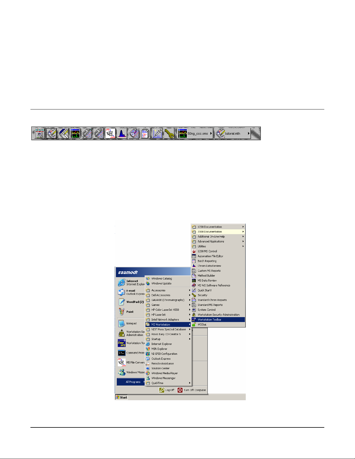
If the MS Workstation Toolbar is not already opened on your Saturn GC/MS
Workstation, you can start it from the Windows Start Menu.
13
Page 16
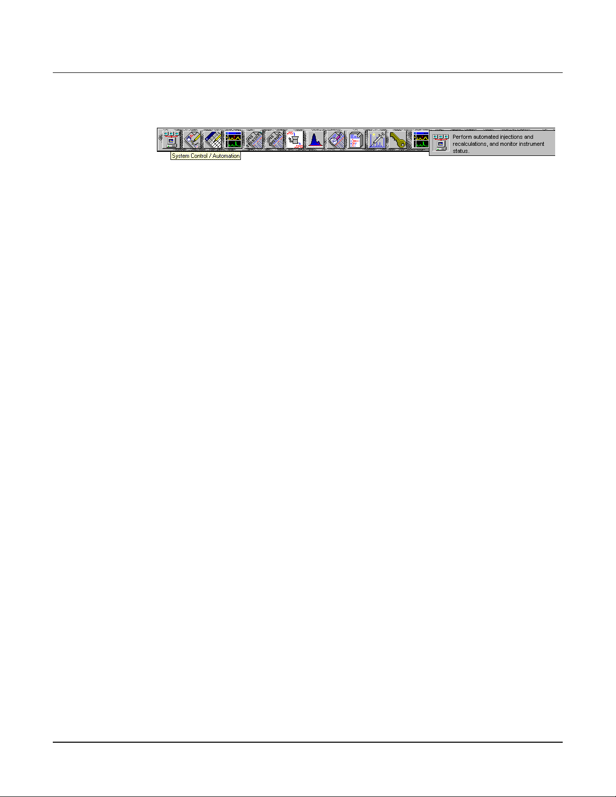
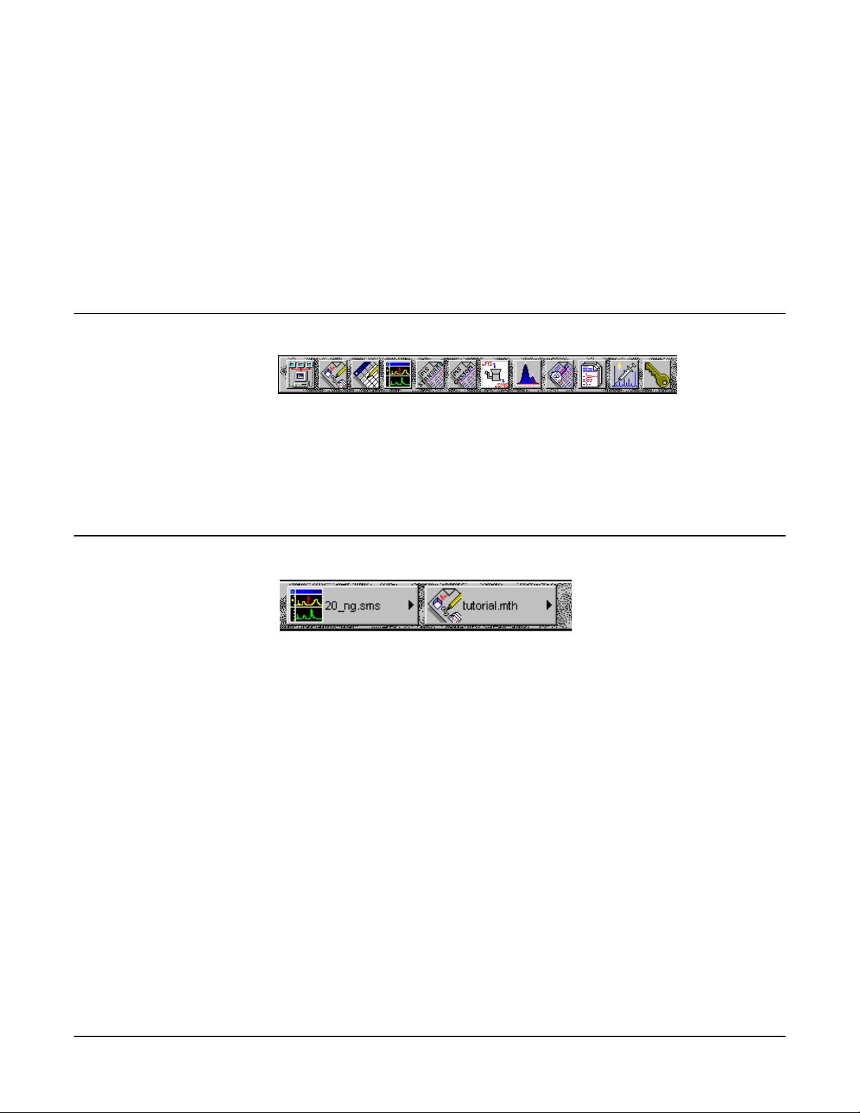
Elements of the MS Workstation Toolbar
Application Buttons for immediate access to the selected application.
Tooltip shows the application name when the cursor rests on the Application
Button.
Quick Link Buttons provide menu selections of operations to be performed on the
listed file.
Application Descriptions give a brief description of the application that will be opened
when the cursor rests on the Application Button.
14
Page 17
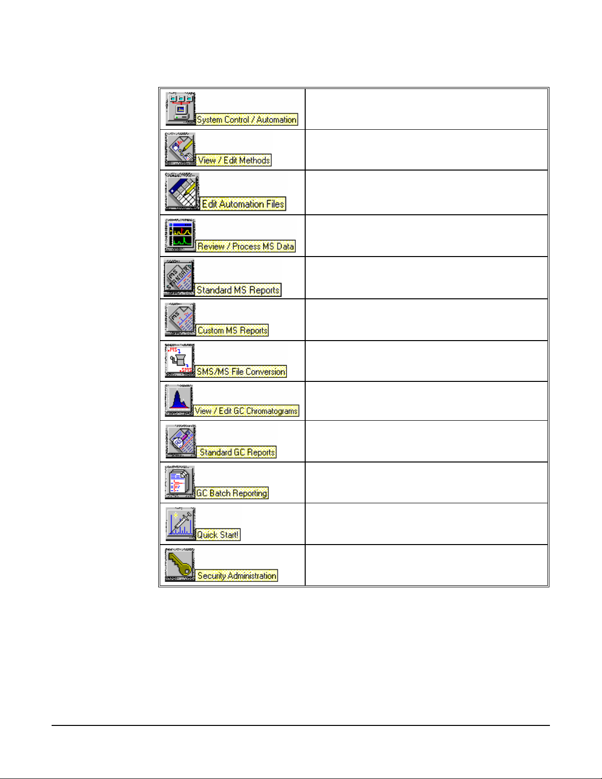
Application Buttons
Used to monitor instrument status, perform automated
injections, and perform batch recalculations.
Used to view and edit instrument operation, data
acquisition, and data handling methods.
Used for off-line editing of SampleLists, RecalcLists and
Sequences.
Used to review chromatograms and spectra, perform library
searches, and review and process quantitation results.
Used to create, edit, and view standard MS reports.
Used to create, edit, and view customized MS reports.
Used to convert data files between DOS and Windows
formats.
Used to review standard GC chromatograms, interactively
edit data handling parameters, and recalculate results.
Used to preview standard chromatogram and results
reports.
Used to generate standard reports for a group of Data Files
by dragging and dropping them on the Batch Report
Window.
Used to run a sample without a Sample List.
Used to set Saturn GC/MS Workstation security options and
passwords.
In addition, other application buttons may be added to the MS Workstation
Toolbar when you install additional Saturn GC/MS Workstation options, such as
StarFinder and Star Custom Report Writer.
15
Page 18
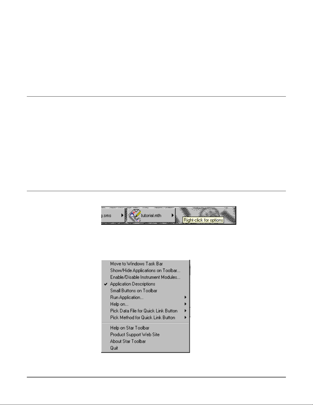
Quick Link Buttons
Most Recently Used Data File. A menu of operations that can be performed on
the Most Recently Used Data File are displayed when the button is pressed. A
different data file can be selected from a list of most recently used files.
Most Recently Used Method. Menu of operations that can be performed on the
Most Recently Used Method will be displayed when the button is pressed. A
different method can be selected from a list of most recently used methods.
16
Page 19
MS Workstation Toolbar Options
Right-click the bar to display the Toolbar Options. A menu of MS Workstation
Toolbar configuration options and operations that may be performed will be
shown.
17
Page 20

18
Page 21
Launching Applications from the MS Workstation Toolbar
Using the Application Icon Buttons
Saturn GC/MS Workstation applications appear as icon buttons on the MS
Workstation Toolbar. As you move the mouse over these buttons, the name of
the application is shown in a tooltip window below the cursor.
Click any icon in the MS Workstation Toolbar to launch the corresponding
application.
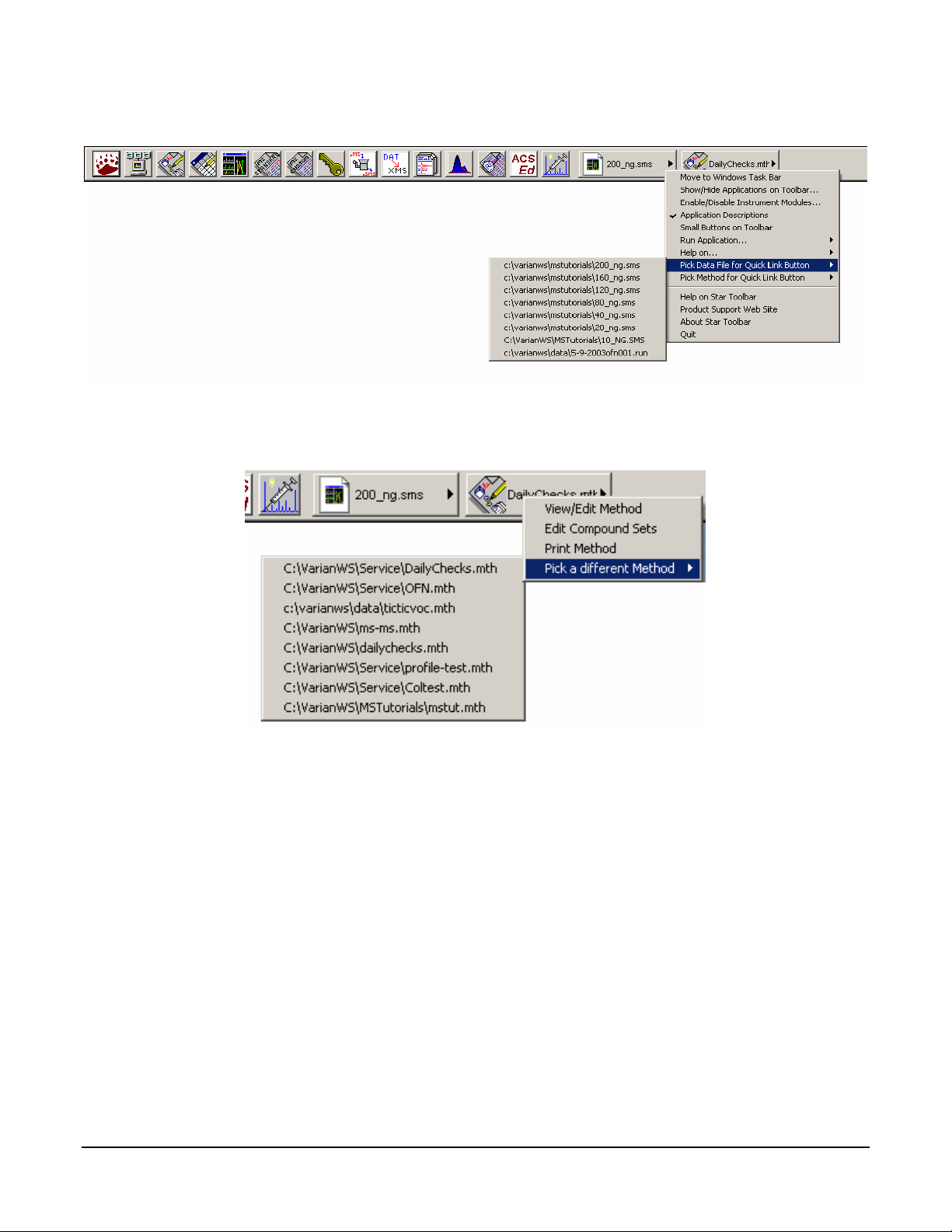
Using the Data File and Method Quick Link buttons
The two buttons to the right of the application buttons are Quick Link buttons.
These two Quick Link buttons correspond to recently used Data Files and
Methods. On each Quick Link button is the name of the file associated with that
button. When you click the Quick Link button, a menu is displayed showing
operations that can be performed on the corresponding file.
The Quick Link buttons in the MS Workstation Toolbar are always updated with
the most recently used Data File and Method. If the Data File or Method you wish
to use is not displayed in the Quick Link button, you can choose from the eight
most recently used files by selecting “Pick a different Data File (or Method)” from
Quick Link button’s menu.
19
Page 22

20
Page 23
MS Workstation Toolbar Options
Moving the MS Workstation Toolbar
The MS Workstation Toolbar can be moved to any edge of the Windows screen.
Click a portion of the MS Workstation Toolbar that does not contain application or
Quick Link buttons and drag the toolbar to the edge of the screen that you desire.
When you release the mouse, the toolbar will remain on that edge. The MS
Workstation Toolbar remembers its location the next time it is started.
Additionally, you can display the MS Workstation Toolbar as a Windows Taskbar
icon. To do so, select “Move to Windows Taskbar” from the MS Workstation
Toolbar options menu. Taskbar icons appear in the lower right (or bottom) of the
Windows Taskbar (the bar on which the “Start” button appears). When displayed
as a Taskbar icon, the toolbar no longer takes up space on the screen. When
you click the MS Workstation Toolbar icon, the options menu is displayed.
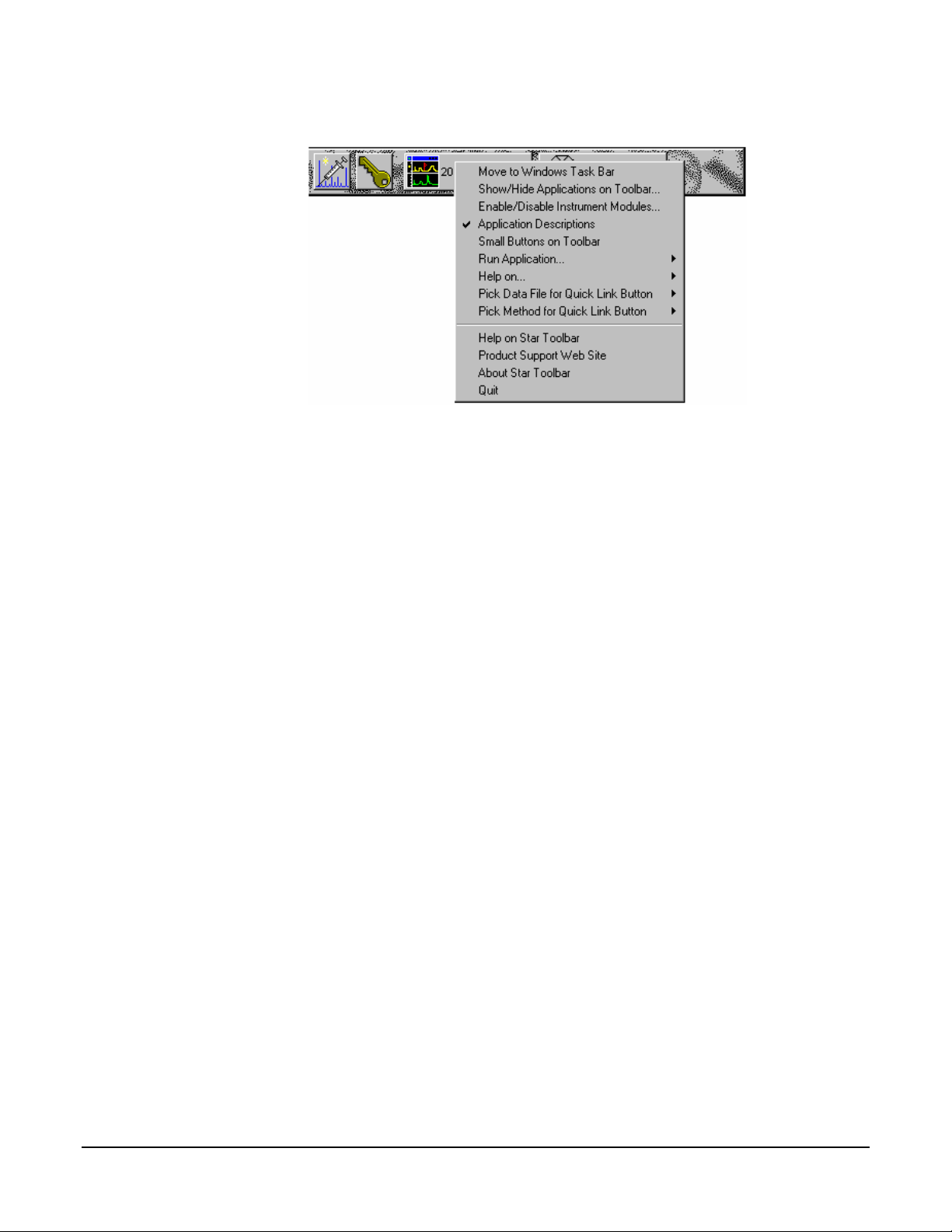
The MS Workstation Toolbar Options Menu
When you move the mouse over an area of the MS Workstation Toolbar not
containing application or QuickLink buttons, you may right-click to display an
option menu.
21
Page 24
Move to Windows Taskbar
You can display the MS Workstation Toolbar as a Windows Taskbar icon.
Taskbar icons appear in the lower right (or bottom) of the Windows Taskbar (the
bar on which the “Start” button appears). When displayed as a Taskbar icon, the
toolbar no longer takes up space on the screen. When you click the MS
Workstation Toolbar icon, the options menu is displayed.
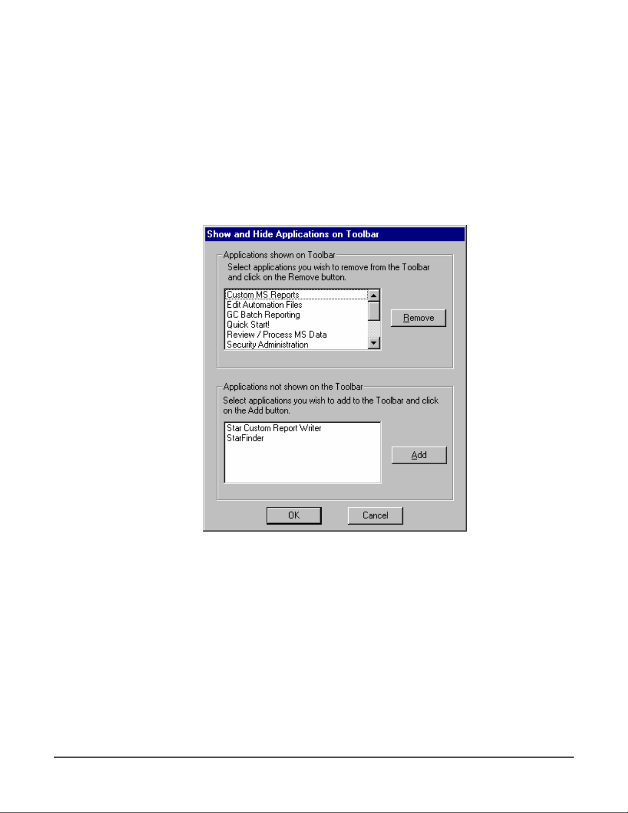
Show/Hide Applications on Toolbar
Selecting this option displays the Show and Hide Applications on Toolbar dialog
box.
This dialog box allows you to select which Saturn GC/MS Workstation
applications are represented by icons on the MS Workstation Toolbar. The top
list box shows all applications that are currently displayed in the toolbar. The
bottom list shows all applications that are installed but not displayed in the
toolbar. To remove an icon from the toolbar, select it from the top list and click
Remove. To add an icon to the toolbar, select it from the bottom list and click
Add.
Enable/Disable Instrument Modules
Selecting this option displays the Enable/Disable Instrument Modules dialog box.
22
Page 25
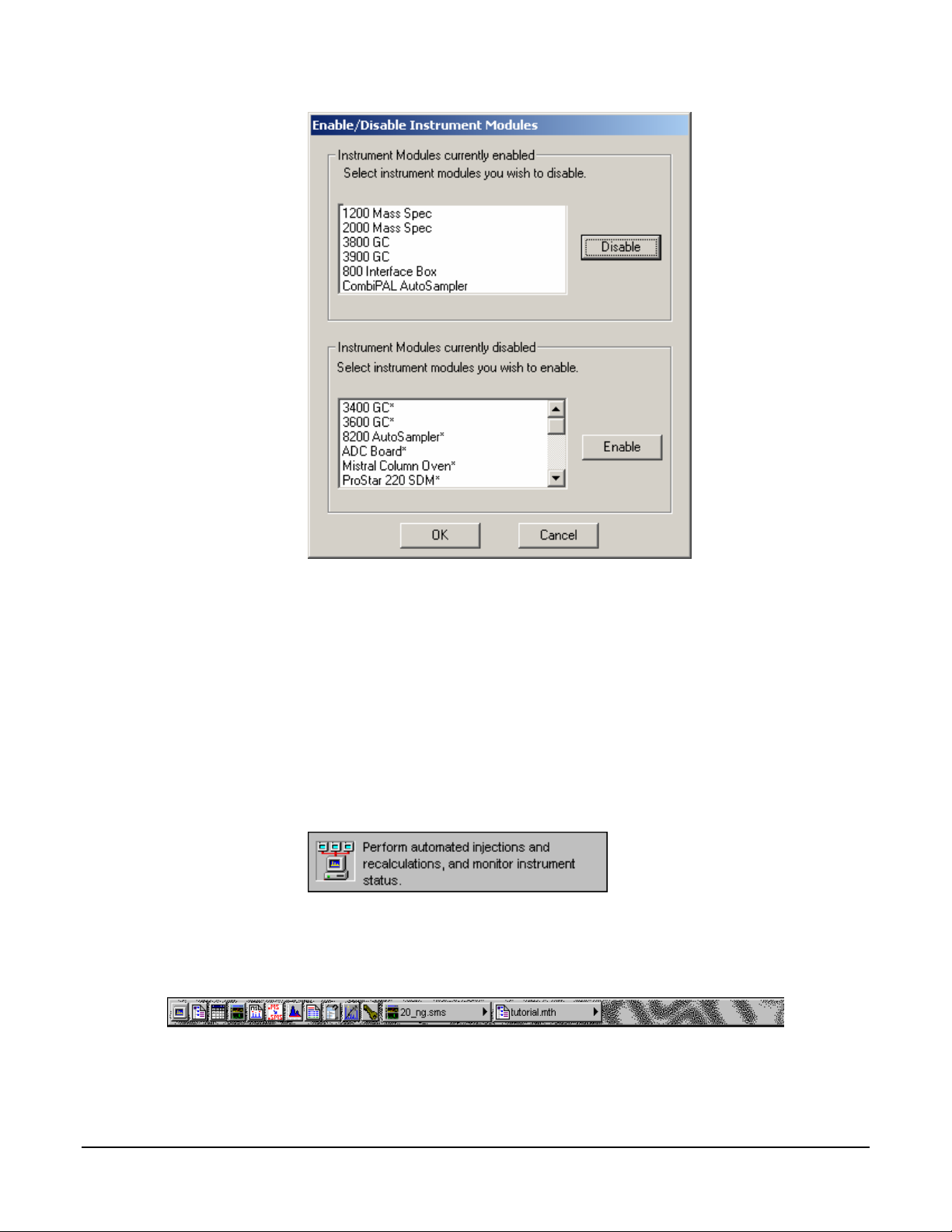
This dialog box allows you to select which Saturn GC/MS Workstation instrument
modules are available from this Workstation. When an instrument module is
available, it will appear in System Control if the corresponding instrument is
connected and powered-on, you will be able to create a Method section for it,
and you will be able to format reports for it.
The top list box shows all instrument modules that are currently installed and
enabled in the Saturn GC/MS Workstation. The bottom list shows all instrument
modules that are installed but not enabled. To disable an instrument module,
select it from the top list and click Disable. To enable an instrument module,
select it from the bottom list and click Enable.
Application Descriptions
When this menu item is checked, application descriptions are displayed when
you move the mouse over application buttons in the MS Workstation Toolbar.
Small Buttons on Toolbar
When this menu item is checked, the MS Workstation Toolbar is reduced in size.
23
Page 26

Run Application
This hierarchical menu item lists all applications showing on the MS Workstation
Toolbar. When you select an item from this list, the corresponding application is
launched.
Help on
This hierarchical menu item lists all applications showing on the MS Workstation
Toolbar. When you select an item from this list, the online help corresponding to
the application is displayed.
Pick Data File for Quick Link Button
This hierarchical menu item lists the eight most recently used Data Files in order
of use. When you select a Data File from this list, the Data File currently
displayed in the Quick Link button is changed to the selected file.
Pick Method for Quick Link Button
This hierarchical menu item lists the eight most recently used Methods in order of
use. When you select a Method from this list, the Method currently displayed in
the Quick Link button is changed to the selected file.
Help on MS Workstation Toolbar
Displays the help you are now using.
Product Support Web Site
If you have Internet access and a web browser installed on your computer, this
option will automatically open the Saturn GC/MS Workstation Product Support
Web Site. Here you will find the latest software and documentation updates for
the Saturn GC/MS Workstation suite of products, along with additional notes,
tips, and answers to frequently asked questions.
You may wish to visit this site periodically to see if new information is available
that may be pertinent to you.
About MS Workstation Toolbar
Displays the About Box for the MS Workstation Toolbar. The About Box contains
information about the software version, installation information, and a list of the
instrument control modules that you have installed.
Quit
Quits the MS Workstation Toolbar application. If you elected to run the MS
Workstation Toolbar automatically when Windows starts, the MS Workstation
Toolbar will reappear the next time you start Windows.
24
Page 27

2000 MS Module Control
Starting System Control the First Time
Before you enter System Control for the first time, confirm that the proper
instrument modules have been enabled and that any instrument modules that
are not part of the system have been disabled. To enable or disable instrument
modules refer to the section of the MS Workstation Toolbar, Enable/Disable
Instrument Modules.
Configuring the Instrument
Before beginning the configuration process, you should know whether you will be
attaching your Workstation and 3800 or 3900 GC to a company network or an
isolated network only used for instrument control. If you have a Network
Administrator on site, you may wish to ask which configuration is recommended.
Use this table to determine the order in which you should read the following
sections.
1. If an Ethernet card has not been installed and configured on your PC, read
Installing and Configuring the Ethernet Card in Your PC and one of the
following:
No Company Network: Configuring TCP/IP Parameters with no
Company Network.
Company Network: Configuring TCP/IP Parameters for a Company
Network.
2. Read Connecting Your 3800 or 3900 GC to Your PC or Network.
If you have not already installed the Varian MS Workstation, do so before
3.
proceeding.
No Company Network: Read Configuring the 3800 or 3900 GC
Communication (No Company Network).
Company Network: Read Configuring the GC for a Company Network.
Continue reading the rest of the sections, starting with Adding a GC and
4.
Varian MS to the Instrument in System Control.
Installing and Configuring the Ethernet Card in Your PC.
5.
NOTE: The following section describes a procedure that is relatively generic;
consult your Windows documentation and that of the Ethernet card’s
manufacturer for more detailed explanations.
25
Page 28
Refer to the installation instructions packaged with your Ethernet card for
information on installing the Ethernet card in your computer. Before proceeding,
your Ethernet card should be recognized by your Windows version. When done,
the Network Neighborhood icon should appear on your Windows desktop.
NOTE: For the following procedure, the use of disks other than the ones that
were used for the original Windows installation may result in a Ethernet driver
version mismatch that keeps Windows from starting. Should this occur, it may be
necessary to remove the Ethernet Board from the computer to remove the
incorrect Ethernet drivers.
You must configure your computer’s network settings to allow communication
with the 3800 or 3900 GC. You do so by running the Windows Control Panel.
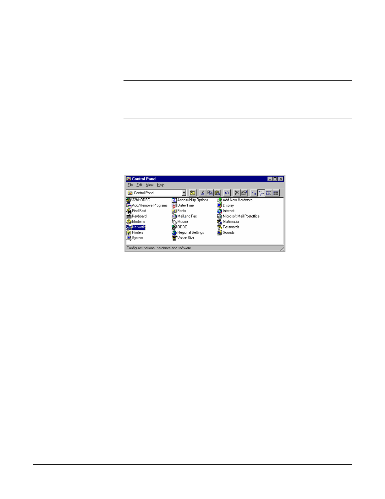
1. Run the Control Panel by selecting it from the Start menu (under Control
Panel or Settings).
The Control Panel window is displayed.
2. Double-click the Network icon to set your Network options.
26
Page 29
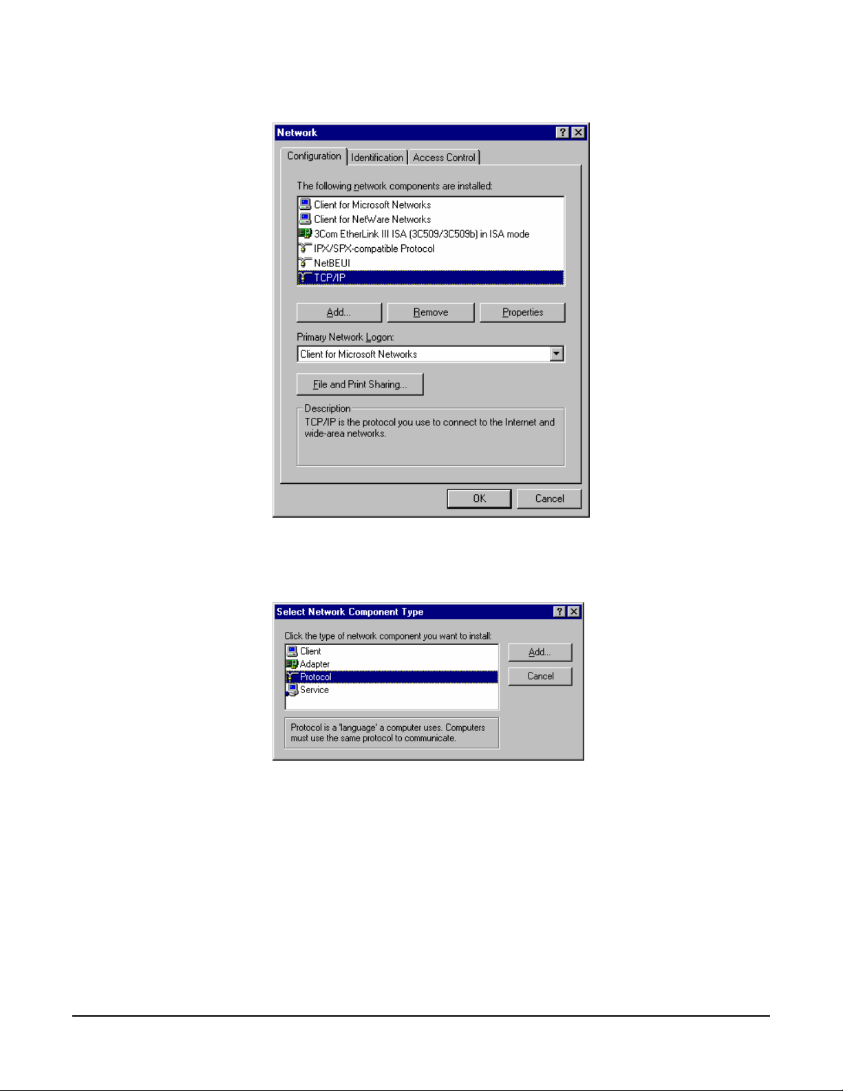
The Network dialog box is displayed.
3. If TCP/IP is already listed in the list of network components, skip to the Note
after step 5, otherwise, click Add.
The Select Network Component Type dialog box is displayed.
4. Select Protocol and click Add.
27
Page 30
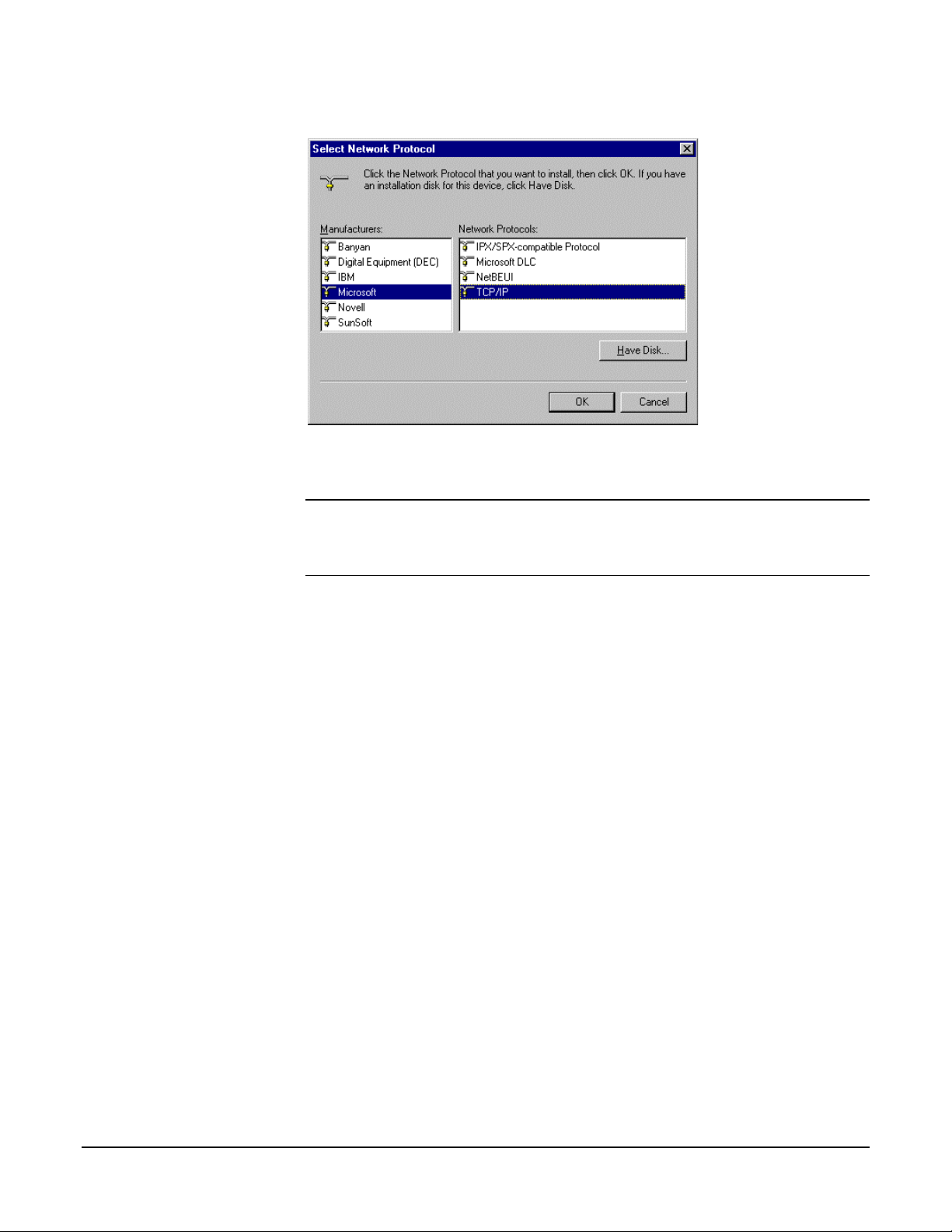
The Select Network Protocol dialog box is displayed.
5. Select Microsoft as the manufacturer. Select TCP/IP as the protocol. Click
OK. The protocol is added to your installed network Component list.
NOTE: If you are not connecting your Workstation to a company network (that
is, you are not assigned an IP address by a Network Administrator), follow the
next three steps. If you are connecting your Workstation to a company network,
skip to Configuring the GC for a Company Network.
Configuring TCP/IP Parameters with no Company Network
The following three steps assume you have completed steps 1 through 5 from
the previous procedure.
1. Select TCP/IP from the network components list and click Properties. The
TCP/IP properties dialog box is displayed.
28
Page 31

Enter an IP address in the range 10.2.128.1 through 10.255.255.254. Note that if you
are adding more than one Workstation to this network, each Workstation PC must
have a unique IP address within this range. The Subnet Mask will be automatically
set to 255.0.0.0. Do not change this value.
29
Page 32

Ensure that no entries have been made in your Gateway, and that Domain Name
Server (DNS) and WINS Configuration have been disabled. These entries are not
used in an isolated network and may cause problems if they are present. Delete
any settings that may have been entered from a previous configuration.
2. Click OK. Reboot Windows for the changes to take affect.
NOTE: Refer to Communication Problems in the Diagnostic and
Troubleshooting section for information about diagnostic tools to verify that your
network installation is correct.
Configuring TCP/IP Parameters for a Company Network
The following three steps assume you have completed steps 1 through 5 from
the previous table.
3. Select TCP/IP from the network components list and click Properties. The
TCP/IP properties dialog box is displayed.
Enter the IP address to be used by this Workstation. Contact your Network
Administrator (or whoever assigns IP addresses in your network) to get the
appropriate address. Note that each Workstation PC must have a unique IP
address. Enter the appropriate Subnet Mask to be used with this IP address.
4. Your Network Administrator may instruct you to obtain an IP address
automatically by selecting the appropriate radio button.
30
Page 33

Contact your Network Administrator (or whoever assigns IP addresses for your
network) to see what the appropriate settings are for your Gateway, and whether
Domain Name Server (DNS) and WINS Configuration are needed.
5. Your Network Administrator may also instruct you to specify parameters in
the Bindings and Advanced tabs.
6. Click OK. Reboot Windows for the changes to take affect.
NOTE: Refer to Communication Problems in the Diagnostic and
Troubleshooting section for information about diagnostic tools to verify that your
network installation is correct.
Connecting Your 3800 or 3900 GC to Your PC or Network
Refer to the Installation Instructions for the 3800 GC Communications Board
(packaged with the 3800 GC Communications Kit) for details on adding the
communications board to your 3800 GC (if not previously installed). Also, refer to
the “Communications” section of the 3800 GC Operator’s Manual or 3900 GC
Operator’s Manual for instructions on connecting your GC to the PC or a
company network. Before proceeding, your GC should be connected to your PC
or network.
31
Page 34

Configuring the 3800 or 3900 GC Communication (No Company Network)
Use the following instructions if either a 3800 or 3900 GC and Varian MS
Workstation PC are being connected to an isolated network, that is, a network
dedicated to Varian MS Workstations and the instruments they control. In this
case, a Network Administrator will not be involved in assigning IP addresses.
NOTE: If you are connecting your 3800 GC and Varian MS Workstation PC to a
multi-purpose company network managed by a Network Administrator, refer to
Configuring the 3800 or 3900 GC Communication (No Company Network).
You may connect one 3800 GC directly to one Workstation…
After you have configured your computer’s network settings start System Control.
Click System Control/ Automation.
When System Control has started for the first time, the Star Assistant
Communication Configuration Wizard will appear to guide you through the setup
and network connections of your 3800 GC. Use the following procedure for
configuring the IP address for your GC.
The first time the Star Assistant guides you through the setup of your 3800 you
will get the following messages:
Read the description presented in each window and click Next.
32
Page 35

From the Setup Ethernet Ports, click Setup for IP Address Management [BOOTP
Server].
Click Setup.
When the Setup BOOTP Server dialog box is displayed, turn on the 3800 or
3900 GC that has been connected to the network.
NOTE: If more than one Workstation is being connected on the same network,
only one Workstation should manage the IP addresses for all GCs connected (all
others should have the Manage IP addresses from this Workstation checkbox
unchecked
conflicts may arise.
As the GC is powered on, an entry is added to the table. For each entry, an IP
address is automatically assigned. For each GC, you provide a host name that
will be used to identify it in the Varian MS Workstation.
). If more than one Workstation is managing IP addresses, naming
33
Page 36

Click the Manage IP addresses from this Workstation checkbox to manage your
GC’s IP address from this Workstation. As the GC is turned on, its Ethernet address
is added to the list.. The IP address is automatically generated. Enter a host name for
each GC. This name is used to identify the GC in the Workstation. You cannot
connect to a GC until you provide it a name. Click OK after entering host names
for each GC.
NOTE: Proceed to Using a Password to Protect BOOTP Settings.
Configuring the GC for a Company Network
Use the following instructions if either a 3800 or 3900 GC and Varian MS
Workstation PC are being connected to a company network, that is, a multipurpose network used for services in addition to instrument control. In this case,
a Network Administrator will be involved in assigning IP addresses. If the GC and
Varian MS Workstation computer are the only devices being connected together,
refer to Configuring the 3800 or 3900 GC Communication (No Company
Network).
You may connect virtually any number of 3800 and 3900 GCs and any number of
Varian MS Workstation computers to a company Ethernet network.
Depending upon your network configuration, all Varian MS Workstations will be
able to control all 3800 and 3900 GCs on the network.
After you have configured your computer’s network settings start System Control.
34
Page 37

Click System Control/Automation.
When System Control has started for the first time, the Star Assistant
Communication Configuration Wizard will appear to guide you through the setup
and network connections of your GC.
NOTE: Before proceeding with this section, consult your Network Administrator
about whether a central BOOTP Server is available on the network.
1. If IP addresses are managed by a central BOOTP Server, then proceed
to Specifying IP Addresses from a Central BOOTP Server.
2. If IP addresses are specified by a Network Administrator but not centrally
managed, then continue reading Specifying IP Addresses from System
Control.
Specifying IP Addresses from System Control
The Varian MS Workstation can be used to specify IP addresses to 3800 and
3900 GCs attached to the network.
Use the following procedure to manage IP addresses form System Control.
The first time the Star Assistant guides you through the setup of your GC you
will get the following messages:
Read the description and click Next.
35
Page 38

From the Setup Ethernet Ports dialog box select Setup to display the BOOTP
Server dialog box.
Select Setup to display the BOOTP Server dialog box.
The BOOTP Server dialog contains a table listing all 3800 and 3900 GCs to
which IP addresses may be assigned.
36
Page 39

NOTE: If more than one Workstation is being connected on the same network,
only one Workstation should manage the IP addresses for all GCs connected (all
others should have the Manage IP addresses from this Workstation checkbox
unchecked). The Workstation acting as BOOTP Server must remain running all
the time to allow other Workstations to connect to GCs. If more than one
Workstation is managing IP addresses, naming conflicts may arise.
Check this box to enable the BOOTP Server.
If 3800 or 3900 GCs are already connected to the network and powered on, their
Ethernet addresses will appear in this table.
You must enter a name for each GC. The IP address will not be assigned to the
GC until a name is entered.
You may manually assign any IP address to any GC. When this item is selected, type
the IP addresses directly into the table. Select OK when all addresses and names
have been entered.
37
Page 40

When the Assign # IP addresses starting from: #.#.#.# radio button is selected,
the bottom portion of the dialog changes.
You may select to consecutively assign IP addresses beginning from a particular
address. Enter the number of IP addresses you want to assign automatically. Enter
the starting address here. As 3800s are powered on, IP addresses are automatically
assigned starting with this address.
NOTE: Proceed to Using a Password to Protect BOOTP Settings.
Specifying IP Addresses from a Central BOOTP Server
If IP addresses are managed by a Network Administrator from a central source,
the 3800 and/or 3900 GCs must be added to the list of devices requiring IP
addresses. IP addresses must be assigned to GCs using a BOOTP Server. A
BOOTP Server lists Ethernet addresses (which are unique to each
communication card installed in each 3800 and 3900 GC) along with the IP
addresses that are to be assigned to the corresponding device. You may obtain
the Ethernet address for each GC from the GC’s front panel or the label on the
Ethernet card within the 3800 GC. Turn on the 3800 GC and press any key to
allow it to start in local mode. The Ethernet address will be automatically loaded
into the BOOTP Server list for 3900 GCs.
START STOP
NOT
READY READY RUN
METHOD
ACTIVATE
EDIT MENU
AUTOMATION
SINGLE METHOD
METHOD SEQUENCE
PRIORITY SAMPLE
SUSPEND RESUME
SELECT/
EDIT
GC CONTROL INSTRUMENT
SAMPLE
DELIVERY INJECTOR
COLUMN
OVEN DETECTOR OUTPUT
PRESSURE
FLOW/
STATUS SETUP
MENU
PAGE CURSOR
TABLE EDIT
NEW
DELETE
LINE
LINE
ENTRY
HELP UNDO
CLEAR
TABLE
ENTERDECRINCR
When the GC has completed its initialization process, press the menu button.
38
Page 41

The Instrument menu is displayed. Press 1 to select the Remote/ Local Control
screen. The Ethernet address, IP address and Alias (which may not yet be
assigned) are displayed.
ACTIVE
METHOD
Method 1 Method 1 0.00 20.00
EDIT
METHOD
REMOTE / LOCAL CONTROL
Ethernet Address: XX:XX:XX:XX:XX:XX
IP Address: XXX.XXX.XX.XXX
Alias: 3800A
CTRL RUN
Enable
TIME
END
TIME
Use the Ethernet address shown here when setting up the BOOTP Server. The IP
Address and Alias (host name) are assigned by the BOOTP Server.
If the BOOTP Server that you are using automatically updates its table with
Ethernet addresses broadcast by devices on the network, then the Ethernet
addresses from 3800 and 3900 GCs connected to your network and powered on
will automatically appear. Note that the frequency with which these addresses
are broadcast by the GC decreases over time to a maximum rate of once per
minute. This means that the BOOTP Server may not receive an Ethernet
address for up to a minute from any given GC.
If you are using a 3800 GC on a 2000R system and the BOOTP Server that you
are using does not automatically update its table with Ethernet addresses
broadcast by devices on the network, then the Ethernet address can be obtained
from the label on the Ethernet card in the 3800 GC.
Once you have entered the Ethernet address for each GC on the network to the
BOOTP Server, power each GC off then on again. Check that the IP address
shown on the front panel of each GC (in the Remote/Local Control screen)
matches the intended address entered into the BOOTP Server. If they do not
match, verify the Ethernet address, updating the BOOTP Server if necessary.
Powering the GC off and on will update the IP address.
NOTE: When IP addresses are managed from central location by a Network
Administrator, the BOOTP Server on your workstation must be disabled. Verify
that the Manage IP addresses from this Workstation is unchecked in the Setup
Ethernet Ports dialog box.
Using a Password to Protect BOOTP Settings
You may wish to restrict access to the BOOTP Server dialog box to avoid
inadvertent or unauthorized changes to IP address assignments. To do so,
enable password protection in the BOOTP Server dialog box. If the Setup
39
Page 42

Ethernet Ports dialog box is not displayed, select the Setup Ethernet
Communications menu item from the Instrument menu to display the Star
Assistant Communication Wizard. Click Next.
Select Setup to display the BOOTP Server dialog box.
The BOOTP Server dialog is displayed.
Check this box to enable password protection.
The next time you enter the BOOTP Server dialog box from the Setup Ethernet
window, you will be prompted for a password.
Enter a password here. Once successfully entered, you may change the password
below. Enter a new password here twice.
The initial password is blank (no password). To set your password initially, enter
the desired password in the Enter new password and Re-enter new password
fields. Subsequent entry into the BOOTP Server will require this password.
NOTE: Refer to Recovering a Lost Password for BOOTP Server Access in the
Diagnostics/Troubleshooting section for instructions on resetting the password.
40
Page 43

Adding a GC and Varian MS to the Instrument in System Control
Once you have configured your Workstation computer and 3800 or 3900 GC for
network communication, you may select one GC to be controlled from each
Varian MS Workstation.
If it is not already running, start System Control. The Star Assistant
Communication Configuration Wizard will be displayed if you have not yet
configured your GC Ethernet connections. Click Next.
Click Address to attach to a 3800 GC on the Ethernet network.
When the Address button is selected, the Module Selection dialog box is
displayed.
Select the GC that you wish to connect to the address (44). Click OK.
NOTE: If you are running on a company network, only GCs on the same local
subnet appear in the Select Available Modules dialog box. To connect to a GC in
a different subnet, type its IP Address directly into the IP address field in the
Setup Ethernet Ports dialog box. Consult your Network Administrator about
subnets on your network.
After you have completed your selection, the Setup Ethernet Ports Dialog Box
shows the 3800 GC connected to your Workstation.
41
Page 44

This 3800 GC is connected to Port 44. The status indicates the availability of the GC.
The IP address of the GC is shown here. Click OK, and wait for the 3800 to connect.
When the GC connects to System Control, it will be represented by an icon at the
bottom of the Configuration Window. The icon will have a label reading 3800.44,
and will include the Host Name of the GC appended to the label. The number 44
is a System Control communication addresses that correspond to the Ethernet
port connected to the device. The same principles are true for the 3900 GC.
Modules and Instruments Defined
The Varian MS system consists of two modules, the 3800 GC and the 2000 MS.
Additionally, a third module is present if you have the 8200 AutoSampler (Note
that the CP-8400 and CP-8410 AutoSamplers will not have a separate icon but
will be included on the 3800 or 3900 Status and Control Window). These
modules also have addresses and the message logs frequently refer to the
module and address. The modules and allowed addresses are listed below.
Module Name Address
Mass Spectrometer 2000 40
Gas Chromatograph 3800 44
AutoSampler 8200 26
Other communication addresses are used for different types of communication
hardware: 16,18,20,22 for Varian ADC Boards; 17,19,21,23 for Varian 3400 and
3600 GCs, and 24 - 39 for Serial Port devices.
If an 8200 AutoSampler is attached to the J4-SID1 connector on the 3800 GC,
the 8200 icon will also appear with the Host Name of the corresponding GC
appended to the label.
NOTE: Refer to the 8200/SPME AutoSampler for 3800 GC Manual for
information about configuring your 8200 for use with the 3800 GC.
42
Page 45

Elements of the Configuration Screen
After the 3800 or 3900 connects to System Control, configure it in an Instrument
by moving its icon from the bottom of the Configuration Window into the
Instrument Area. System Control will remember where to put the icon the next
time that the 3800 connects.
If the 3800 is to be operated with an 8200, make the 8200 the AutoControl
Module. Place the GC icon in the AutoControl Module if either a CP-8400 or CP8410 AutoSampler will be used with the GC. If the 3800 or 3900 is to be
operated without an AutoSampler controlled from the Varian MS Workstation,
leave the AutoControl Module box empty. If you are using a sampling device with
the 3800, the device must be connected to the synchronization port of the GC.
The Varian MS is usually configured into 2 modules, the 2000 and the GC.
Additionally, an 8200 AutoSampler can also be part of the system. After each
module connects to System Control, configure it in an Instrument by moving its
icon from the bottom of the Configuration Window into the Instrument Areas.
System Control will remember where to put the icon the next time that the system
connects.
43
Page 46

Instrument Parameters, Instrument Name, Operator Name, and Instrument status are
listed here. AutoStart Module area. Place the 8200 AutoSampler Module icon in this
box. Module icon showing that 3800 GC Module 44 has been configured to
Instrument #1. Click button to enter or change the Instrument Name, Operator Name,
and Maximum allowable error count. Modules that have logged in and are available
for configuration into an instrument are displayed here.
Once the modules are in place you are ready to proceed.
Setting Instrument Parameters
Some parameters used by the Instrument are set in the Instrument Parameters
dialog box accessed from the Configuration window.
The instrument name appears on reports and in the instrument window. The
operator name appears on reports. The Ready File is used only with older Varian
44
Page 47

software versions (i.e. the forth software system). When the maximum number of
non-fatal errors is exceeded during automation, the automation sequence halts.
Setting this value to zero disables this feature. You are optionally prompted for
this information when you start an automated sequence of injections or
recalculations.
Running an MS Method Without a GC Method
To run an MS method without the GC module or GC method, open System
Control. Under the menu Instrument, select Configuration. Move the GC icon
from the mid field to below the bar labeled Available Modules, by click, drag and
dropping the icon . When a MS method is activated, the GC method will not be
downloaded. To activate the GC and AutoSampler modules, click-drag-drop the
icons into the active field.
NOTE: If an AutoSampler icon is present: click, drag and drop the AutoSampler
icon in the Available Modules area.
45
Page 48

46
Page 49

2000 MS Instrument Control Command Reference
Saturn Module Dialogs
Saturn Module Keypad Dialog
This dialog can be hidden by clicking on Hide Keypad.
47
Page 50

Spectrum Toolbar
Click the green arrow t hide the toolbar. Click the upper left of the full
screen display to restore the toolbar.
Click full scale to normalized to chromatogram. Double-clicking the
chromatogram does the same.
Click to return the xy axes to the previous scale.
Click spectrum plot to open a preview of the spectrum.
Click scale to choose between Auto Scale and Fixed Scale Intensity.
Click mass range to choose between Acquired Mass Range, Fixed
Mass Range, or Maximum.
information.
Click select preferences to change the color of the chromatogram display,
labels, axes, font, and other features.
Click Report Preferences to choose the chromatogram and spectra
options for the standard report.
2000 Module Window
Click to switch graphics or text displays of ion intensity and status
48
Page 51

Item Description
Manual Control Click the Manual Control to turn on or off the trap controls (rf,
Filament, and Multiplier) and to open the CI and Cal gas valves.
Also adjust the rf response, the CI gas pressure, and the Cal
gas pressure. This mode is also used to select the current trap
filament and to adjust the axial modulation voltage. Although
scans may be taken and displayed under method conditions of
any one of the MS Method segments, data may not be acquired
while in this mode. To acquire data, Acquisition Mode must be
selected.
Auto Tune Tune the instrument, including the multiplier setting, mass
calibration, and trap function calibration.
Temperatures Change the temperature of the ion trap or transfer line. Do
bakeout to remove volatile materials absorbed on electrode
surface.
Diagnostics Check the system for status and faults.
Shutdown Shutdown for routine maintenance or for an extended period.
Acquisition Acquire data for a single sample or an automated list .
Manual Control
Ion trap schematic
Item Description
On/Off Turn on or off the ion trap (the filament, rf and multiplier).
Hide Keypad Remove the upper portion of the screen display so that the
Display Selection Select from to view the spectrum in profile or centroid mode.
Turn on or off the rf
Turn on or off the filament.
Turn on or off the multiplier.
Open the valve to turn on the CI gas.
Open the valve to turn on the Cal gas.
lower portion is expanded.
49
Page 52

Instrument Settings
Item Description
Method button Opens the Method Editor program.
Segment # box Select the current segment of the active method.
Scan Mode Ionization mode of the current segment, such as EI-Auto.
Ion Prep. Ion preparation method of the current segment, such as
MS/MS.
Setpoints tab
Item Description
Filament Selection Click to select the current filament. Saturn has 2 filaments so
the system can be used if one burns out.
Axial Modulation
Voltage
Apply button Apply changes you make to the Axial Modulation Voltage. If the
Select the voltage to apply to the upper end caps. Recalibrate
the mass axis when you change this value.
voltage edit control has the focus, press enter to apply the
changes.
Adjustments tab
50
Page 53

Item Description
Adjust Cal Gas Click to adjust the cal gas pressure.
Adjust rf Ramp Change the rf setting for the instrument by turning the screw at
the bottom front panel.
Adjust Set the proper CI reagent pressure for CI analysis. The
pressure is very dependent on the reagent gas used.
Reagent Gas
Selection Box
Done Used when you complete your adjustment.
Choose which CI gas you are using.
Status
Item Description
Mode State Indicates what function the Saturn MS is currently performing, such as
scanning or adjusting cal gas.
Fault State Indicates if a fault has occurred.
Ion Time Indicates the ionization time of the last scan.
Ion Count Indicates the ion count of the last scan.
Auto Tune
51
Page 54

Item Description
Start Auto Tune Begins the event sequence that will tune the instrument. Only
checked boxes will be executed.
Reset Stops the auto tune process.
Continue Starts the next selected function if the single step option has been
checked.
Hide Keypad Causes upper portion of the screen to be removed so that the lower
portion can be expanded in the display.
Display
Selection
Select the display.
Method
Item Description
Air/Water Check Measures the air and water content of the trap, to
determine if there is a leak.
Electron Multiplier Tune Autoset the electron multiplier voltage.
FC-43 Mass Calibration Calibrate the mass axis. Choose Straight Line or FC-43.
Trap Function Calibration Calculate the waveforms for CI, MS/MS and SIS.
Single Step Observe each step in the auto tune process. Use Continue
to proceed after each step.
Set Points
52
Page 55

Item Description
Electron Multiplier Voltage Manual adjustment of the Final Gain Setting determine
from the Auto Tune check.
SIS Amplitude Adjust
Factor
Adjust each trap system for optimum ion sensitivity and
ejection. The voltage adjustment range is between 50 to
200%. The default is 100%.
Temperatures
Item Description
Start Bakeout Execute the bakeout conditions, which removes volatile
material from the ion trap surface.
Reset End a bakeout before the specified time.
Hide Keypad Hide the upper portion of the screen and expand the lower.
Analysis Conditions Set temperature for trap, manifold and transfer line. Click
Apply to initiate conditions.
Bake out Conditions Hold Time specifies the number of hours for bake out. Under
Trap, set the bake out temperature, such as 220 C. The
manifold bakeout temperature is fixed. The transfer line
bakeout temperature matches the analysis temperature.
Diagnostics Mode
53
Page 56

Item Description
Start Click Start to execute the desired test
Reset Cancel a test executed with Start.
System Test
Item Description
Run To Completion Click to run all tests without stopping.
Halt On Error Halts the system checks when an error is detected.
Detailed test of the heater zones
Item Description
Trap Tests the Ion Trap heater element May take up to 13.5
hours to complete.
Manifold Tests the Manifold Heater element.
Transfer Line Tests the Transfer Line heater element.
54
Page 57

Monitor Window
Item Description
Multiplier check box Display the voltage (center left) on the
multiplier when on.
rf check box For Service Engineers.
Filament check box Display the status of the system filaments
(upper right).
Ion gauge check box View the vacuum status using the filament
selected by the Filament Radio Button.
Filament Select a filaments and view the ion gauge
vacuum system test.
Shows current temperature readings for each zone
55
Page 58

Shutdown Mode
Item Description
Shutdown button
Reset button
Shuts down the system in an orderly manner. The pump
speed is slowly reduced and the heaters are turned off so
that the system slowly cools.
Brings the system back to a ready state if the Shutdown
procedure was started. This restarts the pumps and turns
on the heaters.
Diffusion Pump Shutdown Sequence
NOTE: The Diffusion Pump System shutdown sequence takes at least 30
minutes:
The Saturn GC/MS heaters are turned OFF.
The GC temperature zones should be cooled downed before maintenance is
performed.
The diffusion pump heater is turned OFF while the Peltier Baffle cooler is
kept on. The DIFFUSION PUMP STATUS changes from NORMAL to
COOLING. After 15 minutes, when there is no pump vapor to contaminate
the system, the Peltier Baffle cooler is turned OFF. After another 15 minutes,
the cooler has warmed to the point that it won’t condense water vapor, and
the pump is considered to be off. The DIFFUSION PUMP STATUS then
changes from COOLING to OFF.
NOTE: If the word “FAULT!” is displayed in the Vacuum Status box, click
Diagnostics for detailed information.
The Vacuum Status represents the state of the diffusion pump. To precisely
identify the problem, the USER should go to the Diagnostics mode and run
"System Test to Completion”. Fault messages may appear on startup or during
normal operation.
56
Page 59

Turn OFF main power by placing switch at rear of system into OFF (down)
position. Manually vent the system for at least 5 minutes using the lever on front
panel.
NOTE: DO NOT ATTEMPT to VENT SYSTEM by any other method (via transfer
line, foreline vacuum clamps, etc.). Rapid, improper venting of the system will
cause diffusion pump fluid to backstream into the manifold and ion trap.
Maintenance procedures SHOULD NOT BE attempted until the shutdown
program has finished!
Acquisition Mode
Item Description
Start Acquisition button
Reset button
End time button
Hide Keypad button
Display Box Selector
Method button
Click to start the analysis.
Will end the acquisition and reset the
conditions to their initial conditions.
Click to increase or decrease the end time of
the analysis.
Causes the upper portion of the screen to be
removed so that the lower portion can be
expanded in the display.
Allows you to choose among chromatogram,
spectra, or both.
Used to open the Method Editor with the
active method. You can edit the method and
then return to this screen for analysis.
57
Page 60

58
Page 61

2000 MS Instrument Window
The 2000 MS Instrument Window
System Control has four major sections: the System Control Menu bar, System
Control Toolbar, Saturn Keypad Dialog, Chromatogram and Spectrum Toolbar,
and Spectrum Display.
File Menu
59
Page 62

Activate Method allows you to choose a method from those already prepared.
This will set the conditions for the GC, MS, AutoSampler and data handling.
Other sections will also be activated if they are part of the method.
Upload Active Method from Modules
will allow you to get the conditions from the
existing modules to be saved in a new method. Whichever method is active will
now be converted to the conditions of the active modules.
New Sample List
Open Sample List
allows you to open the dialog box to create a sample list.
allows you to select and activate an existing sample list. The
sample list dialog box is shown below.
New Recalc List
Open Recalc List
allows you to open the dialog box to create a recalculation list.
allows you to select and activate an existing recalculation list.
The Recalc list dialog box is shown below.
NOTE: You may process a Recalc List either in System Control (by clicking the
Begin button) or in SaturnView. In SaturnView use the menu command
Quantitation… Process/Review Recalc List to access this feature. Also note
that processing of a Recalc List takes more time when done from System Control
but has the advantage of allowing AutoLink functions such as automated
reporting with SaturnWriter templates.
New Sequence List
Open Sequence List
allows you to open the dialog box to create a sequence list.
allows you to select and activate an existing sequence list.
The sequence dialog box is shown below.
60
Page 63

Edit Menu
Click the Edit menu and highlight Edit Module Info.
Each module in your system (3800GC, 2000MS, 8200 AutoSampler) contains its
own message log and documentation screen. The Module Documentation
screen shown below allows you to keep a record of performance, maintenance,
hours used, or any other comments you wish to make.
Use the Add, Edit, and Delete buttons to record any information you wish about
the MS module.
61
Page 64

Inject Single Sample Menu
The command will allow you to give the sample information prior to an injection.
The dialog box below will appear when this command is invoked. The 2000
module window must be in acquisition mode for the system Not Ready to convert
to Ready and then a manual injection can be made. If an AutoSampler is used,
click Inject in the bottom left corner.
The sample type can be changed by double clicking in the field below Sample
Type. The following displays your choices.
The same procedure can be used for injection notes. Any notes that you wish to
enter here will be saved with the data file. The AutoLink button works in the same
way. Note the picture below.
A command can be entered here to execute a program once the data file
acquisition is completed. For example, this can be a program to activate Saturn
Writer to print the sample reports. To run a SaturnWriter report in automation
enter the directory path and the name of the SaturnWriter template (for example
C:\VarianMS\EPA525.swt). Note that SaturnWriter templates should always be
stored in the VarianWS directory. The browse command can be used to select
the command executable file. Select OK when you have made your selection.
62
Page 65

Automation Menu
Below is a picture of the Automation pull down menu and a description of the
functions.
Begin Sample List
line.
Begin Sequence
automation. An example of this might be to run a set of samples using EI and
then the same set of samples using a different MS method for CI.
Begin At
completed.
Suspend Automation
Resume Automation
where it was suspended.
Stop Automation
Reset Modules
Enable Automated Printing
automation.
starts an automation at a particular line and runs until the last line is
will cause an automation to start at line 1 and end at the last
will allow you to change methods and sample list during an
stops an automation at its last completed sample.
starts the automation after it has been suspended. It starts
ends the automation action.
brings the various modules to there ready states.
allows the printer functions to work during an
Recalculate Menu
The above picture highlights the Recalculate pull down menu. Note that
recalculation may be performed here in System Control or in SaturnView under
the menu command Quantitation… Process/Review Recalc List. Also note
that processing of a Recalc List takes more time when done from System Control
than in SaturnView but has the advantage of allowing AutoLink functions such as
automated reporting with SaturnWriter templates.
63
Page 66

Begin RecalcList will allow you to start an automated recalculation. A
recalculation list must already be prepared and selected to do this. A New Recalc
list may need to be made.
Begin at Selected RecalcList Line
starting with a chosen line and proceeding with the rest of the list.
View Calibration Curves
compounds in the active method. An example of the calibration curve screen is
given below. For a complete explanation of this screen, go to the Quantitation
section.
will allow you to view any of the curves for the calibrated
allows you to process a recalculation list
Instrument Menu
The pull down Instrument menu:
Saturn GC/MS #1
Configuration
necessary if additional hardware is added such as an additional GC detector.
denotes that this is the instrument configured.
allow you to add new modules to the existing instrument. This is
64
Page 67

Instrument 1 Faults allows you to see if there are any faults in any of the modules
contained in Instrument 1. An example of this screen is shown below. The
update key will allow you to periodically check for new faults without opening and
closing the dialog box. 2000 faults are not reported in this window.
Setup Ethernet Communication
between the 3800 GC and System Control.
will allow you to set up the communication
Windows Menu
The pull down menu titled Windows allows you to view any of the windows
associated with the system control. This list is shown in the picture below.
Show Module Windows
configured in the instrument. In this example the module available is the 2000.
Iconize Module Windows
at the bottom of your screen.
allows you to see all of the module windows that are
causes the individual module windows to become icons
Show Automation Windows
These are the Sample list, Recalc list, and Sequence list.
Arrange Icons
Control window.
Sequence List
Sample list
Recalc list
arranges the icons, if any, in a row at the bottom of the System
allows you to display the active sequence list.
allows you to display the active sample list.
allows you to display the active recalculation list.
allows you to view any of the automation screens.
65
Page 68

Instrument 1 Status allow you to view the status of the modules connected to the
system.
Message Log
display is shown below. All error messages for the Saturn Module will show up
here.
2000 module
allows you to view the event log for the MS module. The log
allows you to display the Saturn module control screen.
Help Menu
Click an item in the Contents box to open online help.
66
Page 69

In the Help dialog box, from the Index tab, you can select a particular topic. Click
the selection, go to the bottom of the screen and click Display.
67
Page 70

System Control Toolbar
The system control toolbar is located near the top of your screen. A picture of
this toolbar is displayed below.
Clicking on this button will allow you to create a new automation file.
Clicking on this button will allow you to select a new automation file.
Clicking on this button will allow you to view/edit or print a
method.
Clicking this button will allow you to activate a method.
Clicking on this button will allow you to edit notes for an automation file.
Clicking on this button will allow you to edit module information for any
module that is online such as the 2000, 3800GC, or 8200 AutoSampler.
Clicking on this button allows you to inject a single sample.
Clicking on this button allows you to start a recalculation list if you have one
active.
68
Page 71

Clicking on this button allows you to start a sample list that you have
created. The list must already be selected.
Clicking on this button allows you to start a sequence list that has been
created.
Clicking on this button allows you to suspend a list that is running.
Clicking on this button allows you to begin a list.
Clicking on this button is used to stop a list that is already running.
Saturn Module Keypad Dialog
This dialog can be hidden by clicking on Hide Keypad.
Click Show Keypad to display Saturn Module Modes : Manual, Auto Tune,
Temperatures, Diagnostics, Shutdown, and Acquisition. See Saturn Module
Modes for details.
69
Page 72

Spectrum Toolbar
Click the arrow to hide the toolbar. Click the upper left of the screen to
restore the toolbar.
Click full scale to normalize the chromatogram in the vertical and horizontal
directions. Double-click the chromatogram to do the same.
Click this to return the xy axes to the previous scale.
Clicking on the spectrum plot button will cause a window previewing the
spectrum to be displayed.
Clicking on the scale button allows you to choose between Auto Scale
Intensity and Fixed Scale Intensity.
Clicking on the mass range button allows you to choose between
Acquired Mass Range, Fixed Mass Range, or Maximum.
This button allows you to switch between graphics and text displays of
ion intensity and status information.
Configuring the Real-Time Chromatogram Display
Before performing an analysis the MS module window must be in acquisition
mode. To enter this mode, click Acquisition. During an analysis, observe the
chromatogram in the system control screen. From the following list box ,select
the Chromatogram, Spectrum, or both to be displayed.
70
Page 73

Choosing the Chromatogram only option will allow you to see a live
chromatogram as in the example below.
Click Hide Keypad to expand the chromatogram. Notice in the following picture
the text information at the top is hidden.
To bring the keypad display back, click Show Keypad.
Configuring the Real-Time Spectrum Display
During an analysis it is possible to observe the spectrum in the system control
screen. However, if there are insufficient processor resources, the spectrum
control will not be updated until those resources become available. Selecting the
time selector mode in the chromatogram display will also stop the real-time
update of the spectrum display. In the picture below the drop down list box allows
the selection of Chromatogram, Spectrum, or both to be displayed.
71
Page 74

Choosing the Spectrum only will allow you to see a live spectrum as in the
example below.
Click hide keypad to expanded the display.
72
Page 75

Click Show Keypad to display the keypad.
Status and Control Window
You are now ready to program the GC/MS to perform fully automated data
acquisition. Initially the MS Module Window will look similar to the figure below. If
you do not see this screen, go to the pull down menu labeled Instrument, and
select the item “Saturn GC/MS”.
The upper left side of the window shows the ion trap schematic, which allows the
ion trap to be turned on. If the trap is displayed in red, it is currently disabled. The
trap is disabled if the current segment is a filament/multiplier delay segment, one
with an ionization mode of none, or if a fault has occurred. If the ion trap icon is
not currently disabled, clicking in the center of the ion trap will turn on the trap.
The black schematic will turn green to denote that it is on, as displayed below.
73
Page 76

You must select a method segment that is not a Filament/multiplier delay
segment for the ion trap to be enabled. This method and segment selection is
located in the center of the screen. This center section deals with the active
method and the instrument set points.
The ion trap symbol is a pictorial representation of the ion trap showing the
endcaps (two horizontal curved lines), the rf-voltage ring electrode (two vertical
curved lines), the electron multiplier (a curved cone), the filament (a triangle), the
tank for the CI reagent gas, and the reservoir for the calibration compound. By
clicking on the appropriate part of the ion trap symbol, or by clicking on the
corresponding button, you can turn on and off the various parameters shown in
the symbol (i.e. click triangle to turn on filament). Click in the center of the trap
and the Cal Gas bulb, a spectrum of PFTBA will be displayed.
Method
Now notice the three tabs in the center of the System Module: Method,
SetPoints and Adjustments. There is always an active method controlling the
GC/MS system. This method is the last method selected from a previous use or
the default method if the instrument is just being configured. In the default
method, the first MS Method Segment defines a "Filament/Multiplier Delay."
When such a segment is active, the trap controls are forced off and scans are
not taken to protect the trap from solvent peaks that elute shortly after injection.
This kind of segment is specified in the method by selecting an Ionization Mode
of "None." When such a segment is active in Manual Control, the trap icon
appears red, indicating that the trap is off and that its state cannot be changed.
To actually take (and display) scans, an MS Segment must be specified that has
an Ionization Mode of other than "None." Once this is done, the color of the trap
icon will return to black and the trap may again be turned on by clicking on the
trap icon. (Note that the trap icon may also temporarily appear red while the
system is initializing). Below the method button is the segment number. Click the
up arrow to select segment 2. See Saturn Method Editor for more information on
methods.
74
Page 77

The informational fields displayed in the above dialog are taken from the
currently executing method.
The Scan Mode
example, EI-Auto.
The Ion Prep.
MS/MS.
The Range
describes the ionization mode of the current segment, for
is the ion preparation method of the current segment, such as
will show the mass range being scanned by the current segment.
Operating Conditions
The Operating Conditions located to the far left of the Saturn Module window
allows you to observe the current instrument information.
The Mode State
such as scanning or adjusting cal gas.
The Fault State
will indicate what function the Saturn MS is currently performing
will indicate if a fault has occurred.
The Ion Time
The Ion Count
this is the total ion count. If centroid mode is selected, this is the reconstructed
ion count.
indicates the ionization time of the last scan.
indicates the ion count of the last scan. If profile mode is selected,
SetPoints
The SetPoints tab allows us to select the filament and the axial modulation
voltage. Clicking on that tab will bring up the following screen.
75
Page 78

Two filaments are provided to reduce down time for maintenance. The selection
of the filament is made by choosing the radio button. The Axial Modulation
voltage can be changed by using the up/down arrows and then clicking the apply
button.
The Axial Modulation Voltage is applied to the endcap electrodes as described in
the section Saturn Method Editor. Proper setting of this voltage is critical to
resolution and sensitivity in the ion trap. In most cases, the best Axial Modulation
voltage is the lowest value at which there is still good resolution of the 131/132
and 414/415 cal gas peaks. For most instruments this value will be between 2
and 4 volts.
The Axial Modulation voltage must be adjusted to its proper value before the
AGC target TIC is determined and before the mass calibration is done.
If the value of the Axial Modulation voltage is too low, high molecular weight ions
will not be observed. If the value for the Axial Modulation voltage is too high, the
peak widths for low molecular weight ions will be broadened and mass
misassignments may occur.
NOTE: The mass calibration must be done if the axial modulation setting is
changed. See the autotune section for mass calibration.
Adjustments
The third tab is the Adjustments tab. Clicking on this tab will bring up the screen
below.
This tab is used to adjust the Cal gas pressure, the CI reagent gas pressure,
select the CI reagent, and to adjust the rf ramp.
When you select Adjust rf Tuning Ramp, you obtain a screen from which you
can determine if the rf voltage is in tune throughout the entire mass range of the
Saturn GC/MS. This is done by observing the rf modulator response.
76
Page 79

When the rf Modulator Response screen is displayed, it shows a real time view
of the rf modulator response from 20 to 650 m/z. The vertical axis of the display
is in percentage of counts, and the horizontal axis is mass units. One scan, over
the entire mass range, requires about 1s.
The Counts are displayed as Average rf modulator response and Highest rf
modulator response in counts.
To monitor the rf voltage, observe the displayed ramp. If the rf voltage generator
circuit is properly tuned, the ramp will rise gradually in a generally straight line
from low mass to high mass without any sudden rises in the ramp, and the
Average number counts will be less than 1000. If the rf voltage generator is not
tuned properly all the way to 650 m/z, the end of the ramp will rise sharply at the
mass above which the generator is out of tune, and the Average number of
counts might be above 1000. If this is the case, the rf voltage amplitude must be
adjusted.
The text just to the left of the rf button will tell you if an adjustment is necessary. If
the rf voltage is tuned throughout the entire mass range, you will receive the
following message:
rf response within limits
continue adjustment to minimize highest reading
If the rf voltage is out of tune, you receive the following message:
rf response out of range adjust the rf screw
for a linear response
The rf coil is tuned by adjusting its resonant frequency to match that of the output
of the rf generator board. This is done as follows.
Open the front door and insert a flat head screwdriver into the tuning rod within
the hole labeled “rf ADJUSTMENT” on the lower part of the front panel.
Slowly turn the screw clockwise until the slope of the ramp increases, then turn
the screw counterclockwise until either the slope of the ramp is at its lowest or
there is a sudden rise at the end of the ramp. At that point, turn the screw three
turns clockwise and verify that the Average number of counts is less than 750
and the Highest number of counts is less than 1500. If they are, the coil is
successfully adjusted. If not, run Diagnostics and call a qualified service
representative.
77
Page 80

When it is properly adjusted, the dialog will say the rf response is within limits.
When you are finished, select the Done button.
To adjust the Cal gas pressure click “Adjust Cal Gas”. You obtain a screen from
which you can check and adjust the setting of the calibration compound needle
valve.
When adjusting the cal gas, the following happens automatically. The filament,
electron multiplier, and rf voltage are turned on; the calibration compound
solenoid operated valve is opened; and the scan range is set to display
calibration compound peaks from 45 to 135 m/z. Then, the program determines if
the calibration compound pressure in the vacuum manifold is too low, too high, or
satisfactory.
Under Control and Status dialog box, messages are displayed that indicate the
status of the calibration compound pressure in the vacuum manifold. The
messages are listed below.
Below the dialog box, a progress bar display that shows the status of the
pressure visually.
If the pressure is satisfactory, you will receive the following message:
The calibration gas pressure is OK. Allow time for the gas to flow and the
emission current to equilibrate.
In this case, click Done.
If the calibration compound pressure is too low, you receive the following
message:
Increase calibration gas pressure by adjusting the calibration needle valve.
Allow time for the gas to flow and the emission current to equilibrate.
In this case, turn the calibration compound needle valve 1/4 turn
counterclockwise. Wait for about 30 seconds for the instrument to equilibrate.
Then, note the message again.
If the pressure is too high, you will receive the following message:
Decrease calibration gas pressure by adjusting the calibration needle
valve. Allow time for the gas to flow and the emission current to
equilibrate.
In this case, turn the calibration compound needle valve 1/4 turn clockwise. Wait
for about 30 seconds for the instrument to equilibrate. Then, note the message
again.
If you are using Chemical Ionization you will need to select a CI reagent gas
and adjust its pressure. Select the reagent gas you are using by clicking on the
arrow below the word Adjust.
78
Page 81

In CI, as in EI, the Saturn GC/MS is tuned to achieve the best combination of
maximum peak height (sensitivity), optimum resolution of peaks, and smooth
peak shape. And in CI, as in EI, the key to proper tuning is to optimize the
number of ions in the ion trap: Too few ions, sensitivity suffers; too many ions,
resolution and peak shape suffer.
In CI, the two main factors that affect the number of ions in the ion trap are the
ionization time and the reaction time. (Once again, the emission current is an
important third factor.)
The CI ionization time is the time that energetic electrons, emitted from the
filament, are allowed to interact with reagent gas to form reagent ions. The
reaction time is the time that reagent gas ions are allowed to react with sample
molecules to form ions.
To a first approximation, the number of reagent ions formed is directly
proportional to the ionization time, and the number of sample ions formed is
directly proportional to the reaction time.
Once you have selected methane as the CI reagent gas it is time to adjust the
flow rate of the gas into the mass spectrometer. Make sure that the gas tank is
open and connected to the back of the instrument. Select the adjust button. This
will open the CI valves, turn on the filament and multiplier. You will see the
screen below. This is an example of the CI gas spectrum for methane, when the
CI gas pressure is too low and needs to be increased. Notice the resolution and
relative ratio between masses 10 and 30.
See the Chemical Ionization
section in the Hardware Manual for setup and CI gas adjustment.
79
Page 82

Increase the CI gas pressure by adjusting the CI needle valve on the front of the
2000. Turn the knob clockwise to increase the pressure. When the pressure is
correct you will see the picture below.
If you increase the pressure too much, you will see a picture like the one below
and you will have to decrease the pressure until you get the picture above.
Once the pressure is adjusted properly you are finished and ready to perform
chemical ionization experiments.
Autotune Mode
It is necessary to perform an auto tune when the instrument is first setup.
Additionally, you must recalibrate the mass axis (FC-43 Mass Calibration)
whenever the temperature, axial modulation, or rf adjustment is changed. Each
time the system is shut down the auto tune must be performed when it is
restarted.
There are four major sections to the Auto Tune window: the Control and Status
display, the Method & Set Points, the Operating Conditions display and the
Spectrum and Event Message window.
80
Page 83

Control and Status
The Auto Tune methods are started from this display by clicking on the Start
Auto Tune button. The method maybe stopped by clicking on the Reset button.
The State
function or is idle.
The Function
displays whether the Saturn MS is currently executing an auto tune
shows which tuning function is currently being performed.
Method and Set Points
There are four auto tune checks to automatically set up, tune and calibrate the
mass spectrometer. Air/Water check, Electron Multiplier Tune, Mass Calibration
and Trap Function Calibration.
Set Points are for manual adjustment of the Electron Multiplier Voltage and
the SIS Amplitude Adjust Factor.
5
NOTE: The Air/Water Check will use the last 10
not the manual setting. If the electron multiplier is replaced, the autotune of
Electron Multiplier Tune must be done before the Air/Water Check.
Electron Multiplier Setting and
Operating Conditions
The operating conditions of the auto tune display will vary depending on the
currently executing auto tune function. The display will show the current results
of the function.
81
Page 84

An example: The dialog for the air/water check is shown below.
The mass 28 peak width
is used to determine if air is present in the trap. The
progress bar labeled “Air Level” is a graphical representation of the peak width.
The mass 19/18 ratio value
is used to determine if water is present in the trap.
The progress bar labeled “Water Level” is a graphical representation of the ratio.
Spectrum and Event Message Window
On the left side of the auto tune screen you will see the picture below. You can
select what information you wish to see displayed during the auto tune tests by
clicking on the arrow and selecting from the display options drop down list box.
The Hide Keypad button will cause the upper portion of the screen to disappear
and for the lower portion to be expanded.
The Current Module Attributes is the information stored from the last auto tune.
When you are finished performing the auto tune you can view this information
which is stored in an auto tune log.
82
Page 85

Auto Tune Checks
In the top center of the screen you will see 4 check boxes. These are the auto
tune steps that are to be performed. If your system does not contain SIS, or
MS/MS the Trap Function Calibration does not need to be performed. To perform
the auto tune click the check boxes and click Start Auto Tune.
Each one of the items that you selected in the check boxes will now be executed.
If you checked the single step button, a single step will be executed but will not
proceed to the next until the continue button is clicked. You can stop the auto
tune at any time by clicking on the Reset button.
Air/Water Check
When you select Air/Water Check, you obtain a screen from which you can
determine the relative amount of air and water vapor in the vacuum manifold.
When you display the Air/Water screen, the following happens automatically: The
filament, electron multiplier, and rf voltage are turned on; AGC is turned off; and
the scan range is set to display the air/water spectrum (14 to 44 m/z). To
determine the air background, the width of the peak for mass 28 at 10% peak
height is calculated. To determine the water background, the ratio of mass 19 to
mass 18 is calculated.
83
Page 86

On the left side of the dialog box is an progress bar that indicates the relative
amount of AIR in the system. A message is displayed below the bar.
If the display reads OK, there is essentially no air leak in the system. If the
message MAYBE is displayed, there is a small air leak. The system can be
operated, but performance might not be optimum.
If the display reads HIGH, there is a significant air leak. The leak must be found
and corrected before the system can be operated.
On the right side of the dialog box is an progress bar that indicates the relative
amount of WATER in the system. A message is displayed below the bar.
If the meter reads OK, there is very little water in the system and the system can
be operated.
If the display reads MAYBE, there is a small amount of water, and the system
can be operated, but performance might not be optimum. If the meter reads
HIGH, there is a comparatively large amount of water present in the system, and
the system must be bake out to remove the water before the system can be
operated. (A relatively high water background is generally observed immediately
after you have vented the instrument. It will usually go away within a few hours of
restoring the instrument to its normal operating conditions.)
5
NOTE: The Air/Water Check uses the electron multiplier voltage giving a 10
gain and not the manual setting. If the electron multiplier is replaced. The
autotune of Electron Multiplier Tune must be done before the Air/Water Check.
Electron Multiplier Tune
84
Page 87

The Electron Multiplier Tune will determine three proper settings: the Integrator
Zero, the 10
5
gain for the Electron Multiplier and the Electron Multiplier voltage
boost for optimum peak intensity and resolution.
The Integrator Zero Set obtains the average value of the signal level coming
from the Integrator Circuitry when the filament is off. When the filament is off, the
major source of signal coming from this circuitry is electronic noise. The
Integrator zero is adjusted such that the average value of electronic noise is
slightly greater than zero.
NOTE: The average value for the integrator zero; it should be between 0.20 and
0.80 counts. The Setting can range between 0 and 255.
The Electron Multiplier Tune program can automatically set the electron
multiplier voltage, such that the electron multiplier gain is approximately 10
5
electrons per ion. The program to set the electron multiplier voltage should only
be run when there is no sample of any kind in the instrument. For example, you
should wait at least 30 minutes after you close the calibration compound valve
before you run the program.
5
For the determination of 10
gain, Electron Multiplier Tune program runs in two
phases. In the first phase, the electron multiplier is set to a low test voltage, the
message PRE-ADJUSTMENT PHASE is displayed. The electron multiplier
voltage is increased by 100V increments until a signal is detected coming from
the electron multiplier. The electron multiplier voltage is then set to 300V less
than the value at which a signal was first detected. This ends the first phase.
In the second phase of the program, the electron multiplier voltage is increased
by 100V increments beginning with the final value of the first phase of the
program. In this phase, the Locate Low Voltage End where 10
achieved and Locate High Voltage Start where 10
5
gain is exceeded.
5
gain is not
NOTE: The electron multiplier is approaching the end of its lifetime when the
voltage setting nears 3000 volts.
The final determination is the Electron Multiplier boost, which determines the EM
voltage and AGC Target value for optimum peak intensity and resolution. It uses
the calibration compound peak at mass 131. The program adjusts the target TIC
value to a level that provides reasonable resolution of the major peak and its first
isotope peak. The program determines the height and area of the major peak of
interest, the height and area of the isotope peak, the height of the valley between
the two peaks, and ratio of the height of the valley and the height of the isotope
peak. The Final Gain setting will reflect any increase in the voltage for optimal
85
Page 88

sensitivity and resolution. This setting is also the value displayed in the Set
Points dialog, in the Electron Multiplier voltage field.
Mass Calibration
The mass calibration function adjusts the rf Scale for a coarse full mass range
calibration and, then locates several FC-43 masses for a multi-point calibration
curve.
To initiate mass calibration based on FC-43, click the button to the left of FC-43
Calibration. When you initiate the program, the calibration compound valve is
opened, and the electron multiplier, filament, and rf voltage are turned on
automatically. The program then automatically uses the calibration compound
peaks at masses 69, 131, 264, 414, 464, 502, and 614 to create a calibration
curve.
Factors Affecting the Mass Calibration:
The program also uses the air peak at mass 28 for the calibration of low
masses. Any air leak results in a distorted calibration at low mass. Therefore,
do not run the Mass Calibration program if your instrument has an air leak.
If one or more of the mass peaks are not found by the program, the rf voltage
amplitude might need to be adjusted.
Temperature changes can adversely affect the mass calibration and this
procedure should be initiated after the manifold has reached its equilibrium
point (i.e., approximately 3 hours after the set-point temperature has been
established).
An ideal slope (that of a straight line calibration) is 6.300 steps per atomic mass
unit. You will generally obtain a slope of 6.3 0.1. The standard deviation should
be 0.15 steps per atomic mass unit or less. (If the standard deviation you obtain
86
Page 89

is outside of these limits, check if the rf voltage amplitude is adjusted properly
over the entire mass range).
Straight Line Mass Calibration
To initiate a straight line mass calibration, click Straight Line Calibration and Start
Auto Tune. A straight line calibration assumes a linear relationship between DAC
steps and mass. It is used for certain hardware adjustments. When you initiate
the program, a straight line calibration curve is calculated with the zero DAC step
set equal to 0 m/z and 4095th DAC step set equal to 650 m/z.
Trap Function Calibration
When the mass calibration has completed, the trap function calibration can be
performed, if an MS/MS or SIS key is installed on the SAP/Wave Board. This
calibration determines parameters which are required for the operation of ion
preparation methods such as MS/MS and SIS. It takes several minutes to
complete and the Trap Function calibration should be done each time a mass
calibration is done. If you are not using any ion preparation methods, the trap
function calibration does not have to be done. However, before you activate an
ion preparation method, you must then repeat the mass calibration with a trap
function calibration.
At the completion of Trap Function Calibration, the Event Message Window
displays the secular frequency values for the two trap function calibration points.
Nominal values are 257 and 255, respectively. These values can vary up to 4
KHz between instruments.
Set Points
x
The electron multiplier voltage and the SIS amplitude adjust factor can be set by
either changing the value in the edit box or by clicking on the up/down arrows.
The values are not set until the apply button is clicked and will be reset to their
previous values if the setpoints tab is left before clicking the apply button. If one
of the edit controls has the focus, the enter key can be pressed instead of the
apply button.
Electron Multiplier Voltage. Final Gain Setting determine from the Auto Tune
check of EM.
87
Page 90

SIS Amplitude Adjust Factor. Each trap system must be adjusted for optimum
ion sensitivity and ejection. See Tutorial on SIS Calibration for your system.
The voltage adjustment factor may be set between 50 to 200%. The default is
100%.
Temperatures Mode
The temperature settings to control the Saturn and the transfer line are
accessible by clicking on the Temperature button located in the top center of the
instrument control screen. When you select this a screen like the following
opens.
Click any temperature to change it. After you change a setting, the Apply button
becomes active and you must click this for the changes to occur.
Manifold temperature (range 0°C to 120°C; default = 40°C), the Trap heater
(range 0°C to 250°C; default = 150°C), and the Transfer Line temperature (range
0°C to 350°C; default = 170°C).
The manifold heater is primarily used for baking out the analyzer and should not
exceed 50°C when performing acquisition. The default temperature of 40°C is
recommended. The transfer line temperature should be adjusted so that its
temperature is no lower than that of the trap or the GC oven.
NOTE: DO NOT heat the transfer line above the maximum temperature
specified for the capillary column.
Whenever any temperature is changed, 2 to 3 hours should be provided to allow
the system to equilibrate after the temperature has reached its setpoint. Once
equilibrium is reached, the rf tuning should be checked, and adjusted if
necessary.
The Start Bakeout button will cause the Bakeout Conditions (time and
temperature) to be activated. The reset button will end the bakeout session. The
manifold bakeout temperature is fixed at 120 C. The transfer line bakeout
temperature defaults to its Setpoint temperature.
88
Page 91

Whenever you execute changes, the event log at the bottom of the screen will be
updated with the time and the event that has occurred. The screen below is an
example.
At the conclusion of the bakeout, the trap, and manifold temperatures will return
to the set point values. New setpoint values can be applied during a bakeout. A
bakeout must be halted, by clicking the reset button, before a new bakeout
duration or new bakeout temperatures can be set.
Diagnostics Mode
Click Diagnostics in the top center of the screen.
The upper portion of the screen is divided into 3 sections: Control and Status,
Diagnostic Method, and Monitor States.
An automated diagnostics can be initiated by clicking on the Run to Completion
Box and clicking the Start
89
Page 92

The Monitor and Event Message window will detail results of the basic system.
If a fault had occurred, the message would indicate what test failed and the
source of the problem.
A more detailed test of the heater zones can be done by clicking in the box of the
zone to be tested under Heater Test. To complete these tests can take up to
13.5 hours for the trap, 2 hours for the manifold, and three hours for the transfer
line. The manifold and transfer line tests can be run simultaneously.
At the far right of the window is a dialog box of Monitor States, which allows you
to monitor the multiplier, rf, Filament, and Ion Gauge if present. Click the check
box to activate the selection. Some elements of the diagnostic display are active
if some trap components are not on.
90
Page 93

Also, present temperature values for each of the heating zones is displayed.
Monitoring diagnostics on startup will identify any problems. Please refer to the
Trouble Shooting section of the Hardware manual for additional information.
Shutdown Mode
The shutdown procedure is used to shut the system down in an orderly fashion.
The screen is shown below and it is accessed by clicking on the top button
labeled Shutdown.
After you see the screen and you want to shut down the GC/MS system, click
Shutdown in the left center of the screen, just above the Reset button. This
91
Page 94

action will cause the heaters to be turned off and the system will begin to cool.
Additionally, the turbo pump will be slowly turned off. In the screen below the
shutdown command has been activated. Notice that the turbo pump speed is
being reduced as the temperature is being cooled.
Should you wish to restart the system after you have activated the shutdown,
simply hit the reset button on the left side of the screen above. This will restart
the pumps and turn on the heaters.
After the temperature zones have cooled, turn OFF main power by placing switch
at rear of system into OFF (down) position. Manually vent the system for at least
5 minutes using the lever on front panel.
Diffusion Pump Shutdown
NOTE: During the SHUTDOWN procedure, the MS temperature zones are
reduced (<80°C). The system is manually vented to atmosphere when the trap
temperature is less than 80°C.
From System Control click Shutdown. The Shutdown display appears, click
Shutdown above the reset button.
The shutdown procedure and capabilities for the Diffusion Pump system are
similar to the turbomolecular system.
Shutdown Page
NOTE: The Diffusion Pump System shutdown sequence takes at least 30
minutes:
The Saturn GC/MS heaters are turned OFF.
The GC temperature zones should be cooled down before maintenance is
performed.
The diffusion pump heater is turned OFF while the Peltier Baffle cooler is
kept on. The DIFFUSION PUMP STATUS changes from NORMAL to
COOLING. After 15 minutes, when there is no pump vapor to contaminate
the system, the Peltier Baffle cooler is turned OFF. After another 15 minutes,
92
Page 95

the cooler has warmed to the point that it won’t condense water vapor, and
the pump is considered to be off. The DIFFUSION PUMP STATUS then
changes from COOLING to OFF.
NOTE: If the word “FAULT!” is displayed in the Vacuum Status box, click on the
Diagnostics mode button for detailed information on the cause of the fault.
The vacuum status represents the state of the diffusion pump. To precisely
identify the problem, the USER should go to the Diagnostics mode and run
"System Test to Completion”. Fault messages may appear on startup or during
normal operation.
Turn OFF main power by placing switch at rear of system into OFF (down)
position. Manually vent the system for at least 5 minutes using the lever on front
panel.
NOTE: DO NOT ATTEMPT to VENT SYSTEM by any other method (via transfer
line, foreline vacuum clamps, etc.). Rapid, improper venting of the system will
cause diffusion pump fluid to backstream into the manifold and ion trap.
Maintenance procedures SHOULD NOT BE attempted until the shutdown
program has finished!
Diffusion Pump Startup
NOTE: The Diffusion Pump System Startup sequence takes at least 30 minutes:
First, the Peltier Baffle cooler is turned on while the pump heater is left off. This
step lasts 15 minutes and allows the cooler to drop in temperature before any
pump vapors are created. When the foreline pressure reaches proper vacuum
(~500 mTorr), the pump heater is turned on. When the heater has reached
operating temperature, after approximately 15 minutes, the ion trap electronics
can be turned on.
If a diffusion pump fault occurs the system will go to the shutdown mode. The
USER may check for faults on Startup by going to the Diagnostics mode and
checking the Vacuum Status field for "Fault". "Run Tests to Completion" and
check the event window for messages.
Diagnostics Page to Determine Diffusion Pump Status
93
Page 96

NOTE: The Vacuum System status should be periodically checked during
Startup for foreline pressure. The pressure should read below 500 mTorr in 5
minutes and <
Refer to the Troubleshooting chapter in the Hardware manual.
100 mTorr after 45 minutes. Higher values may indicate a leak.
Acquisition
Selecting the Acquisition button activates the 2000 module for analysis. When
you first go into this screen the module will load the information for the active
method so that it is ready to collect data according to the conditions prescribed in
the method. You will see a screen similar to the one below on the left side of your
monitor.
Within a few moments you will see the red lights turn to green. This is an
indication that the Saturn module is ready for analysis. If the GC and/or
AutoSampler are not ready you will see a Not Ready message at the top of the
screen. Once the GC and AutoSampler come to a ready state, the not ready
message will change to Ready. To determine the individual ready states of the
components you can go the top pull down menu under Windows and see the
states for the 2000, 3800, and 8200 modules. Once all components are ready,
you are ready to start an analysis.
An analysis can be run as a single sample or through an automated sequence.
To run a single sample, go to the top pull down menu called Inject. Select inject
single sample. You will see a screen similar to the one below.
All of the fields in the picture above are editable for your particular sample. Be
sure to give the correct information about sample name, vial position and
injection volume if an AutoSampler is used, and data file path. Once this
information has been entered correctly, select the inject button in the bottom left
corner. If no AutoSampler is used, inject the sample the sample manually when
the GC ready light illuminates on the GC keyboard. If an AutoSampler is used, it
will now be activated and make the injection for you. Refer to the Tutorial Manual
or Help for more information on injection.
94
Page 97

In the above screen there are additional buttons which allow you to browse or
check data files that already exist to make sure that you are not overwriting an
existing file. Prior to making the injection any of these buttons can be selected
and checks can be made.
The sample type can be changed by double clicking in the field below Sample
Type. Note the picture below for the selections that can be made.
The same procedure can be used for injection notes. Any notes that you wish to
enter here will be saved with the data file. The AutoLink button works in the same
way. Note the picture below.
A command can be entered here to execute a program once the data file
acquisition is completed. This can be a program to activate Saturn Writer to print
the sample reports, for example. The browse command can be used to select the
command executable file. Select OK when you have made your selection.
The RecalcList button can be used to create a list of samples for data processing
from the injection that you are making. This will save you some time in creating
the list manually. See the picture below.
95
Page 98

Select one of the 3 radio buttons and name the recalculation list you are using if
appropriate.
In order to perform automated injections of a group of samples you must first
build a sample list and then a sequence list. An example of a sample list is
displayed below. This screen can be activated from the pull down menu under
File, New Sample List. You must create the list from the empty table you see on
your screen. All of the entry fields are the same as the previous information in
this section for single sample injections. Be especially sure that the AutoSampler
vial information is correct in your sample list.
Once the sample list is created, it is time to create the sequence which will cause
the injections to be made. An example is given below. Select Inject for action,
type the name of the method that you wish to run, and type the name of the
sample list you wish to be injected. When this is completed you are ready to
inject your samples. Use the begin button to start the sequence.
General Parameters that Affect EI Operation
Electron Multiplier Gain
Normal Saturn GC/MS operation assumes that the electron multiplier gain is set
up to produce approximately 10
automatically with Auto Tune.
The AGC software operates on information derived from the prescan
measurement of the TIC (the AGC peak).
(See Main Method Editor in the Saturn Method Manual for details of scan
function). Unlike the ionization time or filament emission current that can alter the
actual number of ions created in the ion trap, changing the electron multiplier
gain only alters the amplification of the ion current signal of ions after they are
96
5
electrons per ion. This is accomplished
Page 99

scanned out of the ion trap. Thus, when the multiplier gain is changed, there is
no change in the actual quantity of ions formed and measured in the prescan
measurement, but the peak area of the AGC peak will be changed. The AGC
software will misinterpret this change in peak area as a real change in the
number of ions created in the ion trap and will adjust the ionization time
accordingly. An incorrect ionization time may cause a change in mass resolution.
The AGC software is dependent on the multiplier gain remaining constant in
order to measure the quantity of ions in the ion trap correctly and set the proper
ionization time.
Under certain circumstances (low background, small signal) increasing the
electron multiplier gain by +100 or +200 volts above the 10
5
gain can decrease
the detection limit. As explained in the note above, the same multiplier gain must
be used for determining the calibration curve and analyzing unknown samples.
Axial Modulation
The number of ions stored in the ion trap cavity is proportional to the ionization
time and the filament emission current. Although the maximum ion-storage
capacity of the ion trap is approximately 10
occurs when the number of ions exceeds 10
cause a loss in unit mass resolution. To overcome this limitation, a small ac
voltage, the axial modulation voltage, is applied to the endcap electrodes.
The axial modulation voltage is applied at a fixed frequency and amplitude during
the ramp of the rf voltage. The frequency of the axial modulation voltage is 485
kHz, which is about one-half of the frequency of the rf voltage. Only when an ion
is about to be ejected from the ion trap cavity is it in resonance with this
frequency. When an ion comes into resonance with this frequency, it moves
away from the center of the trap, where the field generated by the rf voltage is
zero (and space-charge effects are strong), into a region where the field
produced by the rf voltage is strong (and space-charge effects are small). As a
result, the ejection of the ion is facilitated, and mass resolution is significantly
improved. The default axial modulation voltage is 4.0. Once the optimum axial
modulate ion amplitude has been set for a given instrument, it need not be
changed.
6
to 107 ions, space-charge repulsion
4
to 105. Space-charge interactions
Emission Current
The number of ions formed in the trap is a function of both the ionization time
and the intensity of the electron beam. In general, increasing the filament
emission current increases the quantity of ions produced. The relationship
between the filament emission current and the measured TIC (i.e., the number of
ions generated in the ion trap) is not a strictly linear one. In particular, the
emission current and the measured TIC do not vary linearly for emission current
values above 40 µA and at high sample concentration.
In certain cases, a high emission current can be used to increase the sensitivity.
One of these is EI/MS/MS where the MS/MS isolation step eliminates the higher
background that would normally arise from a high emission current.
Ion Trap Temperature
After the system has been shut down and the ion trap vented to the atmosphere,
we recommend an initial trap temperature of 220°C for the rapid removal of water
vapor. After this period, a reduction in trap temperature to 150-175°C will extend
the turbomolecular vacuum pump lifetime. Some applications may require higher
97
Page 100

temperatures and this is okay. In general use the lowest temperature which
provides acceptable chromatography. The manifold bakeout functions can be
used to do this overnight and reset the temperatures to operating conditions
automatically.
The trap temperature value selected should be high enough so that
chromatographic performance is not affected. We have found trap temperatures
can be 50-75°C below the ending temperature for the GC column temperature
ramp, without compromising chromatographic performance.
Certain compounds (e.g., straight chain hydrocarbons) will show more
fragmentation at hotter ion trap temperatures.
AGC Target TIC Value
In EI mode with AGC on, the target TIC value determines how many ions AGC
allows into the ion trap during the calculated ionization time. While increasing the
target TIC value will increase peak heights, increasing it too far will result in a
loss of mass resolution. This would be observed as mass misassignments and/or
incorrect isotope abundance ratios. For full-scan EI operation, a target TIC of
20,000 is a good starting point. Under special circumstances, e.g., MS/MS, a
much lower target TIC is required. As the m/z distribution of the stored ions
becomes smaller, fewer ions can be trapped without a loss of resolution.
98
 Loading...