


Varedan Technologies
VSA Series
PWM Servo Amplifiers
VSA-1530-2 Module
VSA-1530-1 Module
VSA-1530-SA Stand Alone
Product User Guide
Revision C

VSA Series Product User Guide
Record of Revisions
Rev Date Valid For Description
A1 1/4/2011 Beta Units Initial release
B 4/19/11 Production Added commands and drawings
C 9/14/11 Production Added Stand Alone information
Technical changes to improve performance may be made at any time without notice!
All rights reserved. No part of this work may be reproduced in any form without written permission from
Varedan Technologies.
Page 2

VSA Series Product User Guide
Contents
1 Introduction .......................................................................................................................................... 5
1.1 Model Part Numbering .......................................................................................................................... 8
2 Safety Information................................................................................................................................ 9
2.1 Hazardous Voltage Information............................................................................................................. 9
2.2 Airflow and Cooling ............................................................................................................................... 9
2.3 Selecting a mounting area..................................................................................................................... 9
3 Module Specifications ........................................................................................................................ 10
3.1 Mechanical & Environmental............................................................................................................... 10
4 Stand Alone Specifications ................................................................................................................ 11
4.1 Mechanical & Environmental............................................................................................................... 11
5 Electrical Specifications ..................................................................................................................... 12
5.1 I/O Interface Drawings......................................................................................................................... 13
5.1.1 Digital Inputs..................................................................................................................................... 13
5.1.2 Digital Outputs.................................................................................................................................. 13
5.1.3 High-Speed Digital Input .................................................................................................................. 13
5.1.4 Regen Output ................................................................................................................................... 14
5.1.5 Analog Inputs DAC A+, DAC A-, DAC B+, DAC B-.......................................................................... 14
5.1.6 High Current Output ......................................................................................................................... 14
5.1.7 Encoder Inputs and Outputs............................................................................................................. 15
5.1.8 Hall Inputs ........................................................................................................................................ 15
5.1.9 Motor Temperature Switch Input ...................................................................................................... 15
6 Connector Descriptions...................................................................................................................... 19
6.1 Main Signal Connector ........................................................................................................................ 19
6.1.1 Main Signal Connector for 2-Phase Models..................................................................................... 19
6.1.2 J1 Main Signal Connector (-1 and -3 models).................................................................................. 20
6.2 J2 Motor Feedback Connector (-1 and -3 models only)...................................................................... 21
6.3 Motor and Power Connectors.............................................................................................................. 22
6.3.1 Module Motor and Power Connectors.............................................................................................. 22
6.3.2 Motor Connector For Stand Alone Model (Front of Stand Alone Case)........................................... 22
6.3.3 AC Power Connector For Stand Alone Model (Rear of Stand Alone Case)..................................... 23
6.4 J4 USB Connection Micro USB-B (optional) ....................................................................................... 23
6.5 J5 RS-232 Serial Interface Connector (optional) ................................................................................ 23
7 Amplifier Input Power Requirements ................................................................................................. 24
7.1 Module DC Input Power ...................................................................................................................... 24
7.2 Stand Alone AC Input Power............................................................................................................... 24
8 User Intefaces.................................................................................................................................... 25
8.1 Serial Interface .................................................................................................................................... 25
8.1.1 RS232 Serial Interface ..................................................................................................................... 25
8.1.2 USB Interface ................................................................................................................................... 25
8.1.3 Communication Format.................................................................................................................... 26
8.2 Pusbutton Switch S1 ........................................................................................................................... 27
8.3 Firmware Programming Switch S2 & LED D2..................................................................................... 27
8.4 Status LED .......................................................................................................................................... 28
9 Protection Functions .......................................................................................................................... 29
9.1 I2T Over Current Protection................................................................................................................. 29
9.2 Internal Protection ............................................................................................................................... 30
10 Modes of Operation........................................................................................................................ 31
10.1 Single-Phase or Brush Motor Torque Mode...................................................................................... 32
10.1.1 Single Phase Torque Mode Settings.............................................................................................. 32
10.2 Single-Phase Veolcity Mode.............................................................................................................. 33
10.2.1 Single-Phase Velocity Mode Settings............................................................................................. 33
10.3 2-Phase Sine Mode (External Sine Commutation) ........................................................................... 34
Page 3

VSA Series Product User Guide
10.3.1.1 2-Phase Sine Mode Settings................................................................................................... 34
10.4 Three-Phase Torque Mode ............................................................................................................... 35
10.4.1 Three-Phase Torque Mode Settings .............................................................................................. 35
10.5 Three-Phase Veolcity Mode .............................................................................................................. 36
10.5.1 Three-Phase Velocity Mode Settings ............................................................................................. 36
10.6 Three-Phase Position Mode.............................................................................................................. 37
10.6.1 Three-Phase Position Mode Settings............................................................................................. 37
10.7 Three-Phase Commutation Phase Finding....................................................................................... 38
10.8 Three Phase Mode Modulation ......................................................................................................... 38
10.8.1 Space Vector or Field Oriented Control ......................................................................................... 38
10.9 Traditional Sinusoidal Modulation ..................................................................................................... 38
11 Command List ................................................................................................................................ 39
12 Appendix A – Sending and Receiving Setup Files ......................................................................... 47
12.1 Capturing Settings............................................................................................................................. 47
12.2 Manually Creating a Settings File...................................................................................................... 47
12.3 Edit the Captured Settings ................................................................................................................ 48
12.4 Sending Files To The Amplifier ......................................................................................................... 48
13 Appendix B – Firmware Updates.................................................................................................... 49
14 Sales and Service........................................................................................................................... 49
Page 4

VSA Series Product User Guide
1 Introduction
This manual describes the operation and installation of the VSA series PWM servo amplifiers
manufactured by Varedan Technologies. This is the section most people skip over, but it does have some
useful information, so please take the time to read it.
The VSA Series Pulse Width Modulated (PWM) Servo Amplifiers are designed for high performance
OEM applications requiring PWM switching type amplifiers. These fully digital servo amplifiers are
available in a variety of power ranges to drive three-phase brushless motors, single-phase brush-type
motors or voice coils. These amplifiers operate in position, velocity, or torque (current) mode using either
an analog input or digital command, or 2-phase sine input mode using analog inputs.
Programmable commutation options include sinusoidal from a motor mounted encoder, externally
commutated 2-phase sine input or trapezoidal commutation using motor mounted hall sensors.
Packaging options include a DC powered module or an AC line powered stand-alone.
Most connections are identical between the module and the stand alone with the exception of the motor
connector and the power connector. Please refer to section 6.
The design of these amplifiers includes an on-board high-speed Digital Signal Processor (DSP) which
performs the PID loop controls as well as monitors all key system functions in real-time to protect the
amplifier in the event of a system fault.
Serial communication options include both USB and RS-232 interfaces. An intelligent operating system
allows setup and storage of all system parameters using simple ASCII command over the serial interface.
The serial interface can also be used to view all operating parameters in real-time. Non-volatile memory
provides storage of the parameters during power off conditions.
A front-panel 7-segment LED display provides real-time indication of system status. Depending on the
mode of operation, up to 20 errors conditions are monitored by the DSP in real-time. The DSP disables
the outputs and displays an error code in the event of system malfunction.
The amplifier has a built in operating system that has many commands to perform the set up and
configuration of the unit. While it may seem daunting at first to have to learn all of these commands, only a
handful are typically used by any particular application. The large number of commands allows this
amplifier to be extremely flexible so it can easily be used across many different applications. Please feel
free to contact the factory for help with configuration and proper use of the commands.
For most applications, once the configuration is set using the serial commands, a simple WRITE
command is issued to save the settings in internal non-volatile memory (NVM). Following the WRITE
operation, all settings will be restored following a power-on reset so in most cases, no serial
communication is required one the unit has been set up and the settings saved. To automate the process
of setting up multiple units with the same configuration, a text file can be downloaded to each unit over the
serial interface.
Page 5

VSA Series Product User Guide
1.1 Main Parts
1.1.1 Module Parts
USB/RS232Connection
DSP Program Switch
Status LED
Signal Connector
Reset Switch
Feedback Connector
DC Bus Connector
Motor Connector
Baseplate
Page 6

VSA Series Product User Guide
1.1.2 Stand Alone Parts
USB/RS232Connection
DSP Program Switch
Status LED
Signal Connector
Reset Switch
Feedback Connector
Motor Connector
Baseplate
AC Power Input
Page 7

VSA Series Product User Guide
2 Model Part Numbering
The following table illustrates the various part numbers used to define the available model configurations.
2.1 Modules
VSA - 1530 - 170 - 1 - 1
Varedan switching amplifier
Continuous Power
Peak Power
Maximum DC Bus Voltage
Hardware Configuration Code
1=Standard Module (as shown top left)
2=Alternate Connector Configuration (as shown top right)
3-999=Other customer specified configurations
Software Configuration Code
1=Standard configuration
2-999 = Customer specific options
2.2 Stand Alone
VSA - 1530 - SA -170 - 1 - 1
Varedan switching amplifier
Continuous Power
Peak Power
Stand Alone Package
Maximum DC Bus Voltage
Hardware Configuration Code
1=Standard Module (as shown above)
2-999=Other customer specified configurations
Software Configuration Code
1=Standard configuration
2-999 = Customer specific options
Page 8

VSA Series Product User Guide
3 Safety Information
You REALLY need to read this information before operating this amplifier.
3.1 Hazardous Voltage Information
Hazardous voltages are present at the motor output terminals, input
power connection, and within the sheet metal enclosure.
Disconnect the power before plugging / unplugging any
connections or before servicing or disassembling the enclosure.
3.2 Airflow and Cooling
CAUTION
The user must insure proper airflow for the application. Failure to
do so may cause permanent damage to the unit and is not covered
3.3 Selecting a mounting area
The VSA amplifier module should be mounted in a solid, clean, dry location with adequate ventilation.
Avoid mounting areas that:
Obstruct the intake or exhaust vents.
Allow dust, debris to enter and contaminate the cooling capability of the drive.
Have humidity above 80% or are susceptible to moisture or coolant.
Are prone to corrosive or flammable materials.
Have an ambient temperature higher than 85°F (30°C).
Are under water.
Vibrate, are susceptible to vibration or that could transmit the cooling fan vibration to sensitive
test equipment.
CAUTION
under warranty.
Page 9

VSA Series Product User Guide
4 Module Specifications
4.1 Mechanical & Environmental
Size 7.125 X 4.60 X 1.45 inches
Weight 0.94 lb (0.43 kg)
Ambient temperature 0 to +45 °C operating, -40 to +85 °C storage
Humidity 0% to 95%, non-condensing
Contaminants Pollution degree 2
Environment IEC68-2: 1990
Cooling Heat sink and/or forced air-cooling may be required for continuous power output
Figure 1: VSA Module Dimensions
7.1250
1.4500
4.6000
0.8000
1.4500
6.7250
3.2500
4.6000
0.7300
7.1250
7.1250
0.8000
1.4500
6.7250
Page 10

VSA Series Product User Guide
5 Stand Alone Specifications
5.1 Mechanical & Environmental
Size 7.125 in X 4.60 in X 2.50 inches
Weight 0.94 lb (0.43 kg)
Ambient temperature 0 to +45 °C operating, -40 to +85 °C storage
Humidity 0% to 95%, non-condensing
Contaminants Pollution degree 2
Environment IEC68-2: 1990
Cooling Heat sink and/or forced air-cooling may be required for continuous power output
Figure 2: VSA Stand Alone Dimensions
STAND A LONE DI GITAL PWM AMPLIFIER
1 2
Line
AC
Neutral
3
Earth Ground
Motor C
Motor B
Motor A
J3
123
Bottom Surface
Bottom Surface
VSA-1530-SA
VSA-1530-SA
STAND ALON E DIGITAL PWM AMPLIFIER
Encoder Controller I/O
Reset
J2 J1
Status Display
DSP Program
RS232 / USB
Page 11

VSA Series Product User Guide
6 Electrical Specifications
Module Stand Alone
MODEL
Input Voltage 70-340 VDC 70-340 VDC 80-240 VAC Single-Phase
Motor bus = AC Input Volts * 1.414
Output Power
Peak Current 30 50 30 50 Amps
Peak time 1 1 1 1 Seconds
Continuous current 15 20 15 20 Amps
PWM Outputs 20 kHz center-weighted PWM (Can be factory adjusted)
PWM Ripple Frequency 40 kHz (Can be factory adjusted)
Commutation and Control
Current loop 20 kHz (50 µs period) update rate
Velocity Loop 4 kHz (250 µs period) update rate
Position loop 1 kHz (1mS period) update rate
Commutation Field Oriented Control (FOC) or Traditional Sinusoidal
Phase Initialization Selectable: Hall startup then sinusoidal from encoder
Encoder startup, no halls required
External 2-phase analog sine input
Bandwidth 3 kHz typical, varies with load inductance
Minimum Load Inductance 400uH line to line
Current Monitor Output
Output Voltage Range 0-10 VDC 0-10VDC
Scaling 1V = 4 Amps 1V=6 Amps 1V = 4 Amps 1V=6 Amps
Serial Interface
Interface Type RS-232 or USB
Baud 115k
Data Format 8 Data bits, No Parity, 1 Stop Bit
Protocol ASCII
Encoder Power Supply Output
Output Voltage +5 VDC
Maximum Output Current 250mA, Internally fused
VSA-1530 VSA-2050 VSA-1530-SA VSA-2050-SA
Page 12
VSA Series Product User Guide
6.1 I/O Interface Drawings
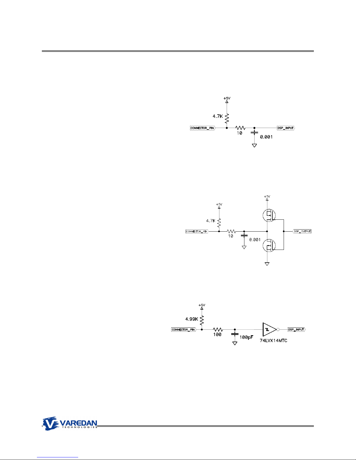
6.1.1 Digital Inputs
The following drawing shows the circuitry for Enable, Reset, Fault and the User I/O pins when configured
as inputs.
Fault, Enable, Reset, User1,2,3,4 Configured As Inputs
Input Voltage Range 0-5 VDC
Internal Pull-up 4.7k ohms
Absolute Maximum Voltage 5.5 VDC
Logic High +2 to +5 VDC
Logic Low -0.5 to 0.8 VDC
Filter 16MHz
6.1.2 Digital Outputs
The following drawing shows the circuitry for Fault and User I/O pins when configured as outputs.
Fault, User 1,2,3,4 Configured As Outputs
Internal Pull-up 4.7k ohms
High Level Output Current -10mA
Low Level Output Current 25mA Maximum
High Level Output Voltage 4 VDC
6.1.3 High-Speed Digital Input
The following drawing shows the circuitry for the High-Speed digital input.
Input Voltage Range 0-5 VDC Schmitt Trigger Input type 74LVX14
Internal Pull-up 4.99k ohms
Absolute Maximum Voltage 7 VDC
Logic High Threshold +2.2 VDC
Logic Low Threshold 0.9 VDC
Filter 16MHz
Page 13

VSA Series Product User Guide
6.1.4 Regen Output
The following drawing shows the circuitry for Regen output. This output can be used to control an external
relay when the bus voltage exceeds a preset level. The relay should have a dumping resistor connected in
a manner that will safely handle the extra voltage.
Output Type Digital
High Level Output Voltage 3 VDC @Ioh = -50uA
Low Level Output Voltage 0.1 VDC @Ioh = -50uA
6.1.5 Analog Inputs DAC A+, DAC A-, DAC B+, DAC B-
The following drawing shows the typical analog input circuitry for the DAC inputs. The inputs are scaled to
accept a maximum of +/-10 VDC. For single-ended operation, apply the voltage to the DAC + input and
connect the signal ground to the DAC - input.
Input Voltage Range +/-10VDC Differential, non-isolated
Maximum Voltage +/-10VDC
Input Impedance 10k ohms
Resolution 12-bit
6.1.6 High Current Output
The high current output is a general-purpose output driven by an open drain MOSFET. It can sink up to
500mA of current.
Output Type Open Drain MOSFET
Internal Pull-up 4.7k ohms
High Level Output Current -5mA
Low Level Output Current 500mA Maximum
High Level Output Voltage 5 VDC
Page 14

VSA Series Product User Guide
6.1.7 Encoder Inputs and Outputs
The following drawing shows the typical encoder input circuit. Jumper JP3 controls the encoder load. With
the jumpers all in, 100-ohm resistors are place across the encoder inputs as shown. When Encoder Type
is set to “S” in software for single ended, the 1K ohm pull up/pull down pair is switched in as shown.
If using JP3, always insert or remove all 3 jumpers at a time. JP3 is located under the cover directly
behind the Reset button.
Encoder Inputs A+, A-, B+, B-, I+, I-
Input Type Single-ended or RS-422 Differential
Single Ended Input Voltage Range 0-5 VDC
Differential Input Voltage Range +/-5.8 VDC
Absolute Maximum Differential Voltage +/-12 VDC
High Level Input Voltage +2 VDC
Low Level Input Voltage 0.8 VDC
Maximum Switching Frequency 25MHz
Input Termination 100 ohms, software configurable
Encoder Outputs A+, A-, B+, B-, I+, I-
Output Type RS-422 Differential Line Driver
High Level Output Voltage 3 VDC @Iol=20mA
Low Level Output Voltage 0.2 VDC @Iol=20mA
Differential Output Voltage 2.6 VDC @Rload = 100 ohms
Maximum Switching Frequency 25MHz
6.1.8 Hall Inputs
The following drawing shows the typical hall input circuitry.
Input Voltage Range 0-5 VDC Schmitt Trigger Input
Internal Pull-up 1k ohms
Absolute Maximum Voltage 7 VDC
Logic High Threshold +2.2 VDC
Logic Low Threshold 0.9 VDC
Filter 3.3kHz
6.1.9 Motor Temperature Switch Input
The motor temperature switch input is designed to connect to a motor mounted thermal switch, either an
PTC or open contact type device. The active level of the fault condition can be set in software.
Input Voltage Range 0-5 VDC Schmitt Trigger Input
Internal Pull-up 1k ohms
Absolute Maximum Voltage 7 VDC
Logic High Threshold +2.2 VDC
Logic Low Threshold 0.9 VDC
Filter 3.3kHz
Page 15
L1
L2
Fuse
Fuse
Line
Earth Ground
!
VSA Series Product User Guide
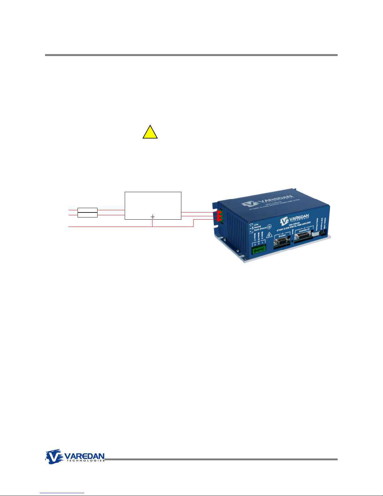
6.2 Stand Alone AC Input Power Wiring
The following drawing shows the recommended connection for the AC input to the stand alone package.
Connect the AC mains and earth ground to the appropriate pins on the mating connector and double
check the wiring before plugging the mate into the amplifier. The warranty does not cover damage due to
improper wiring of the power connector.
DANGER
Hazardous voltages are present at the motor output terminals, input power connection, and within the
sheet metal enclosure. Disconnect the power source before plugging / unplugging any connections or
before servicing or disassembling the enclosure.
Earth
Ground
Line
Line Filter
Load
Page 16

+
-
A
C
A
C
A
C
VSA Series Product User Guide
6.3 Stand Alone Motor Wiring
6.3.1 Three-Phase Motor Wiring
6.4 Single-Phase Brush Motor Wiring
Case Ground
Case Ground
Brushless
Servo
Motor
Brush
Servo
Motor
Page 17

A
C
A
C
+
A
C
A
C
+
VSA Series Product User Guide
6.5 Module Motor and Bus Connections
6.5.1 Three-Phase Motor and Bus Connections
6.5.2 Single-Phase Motor and Bus Connections
DC
Bus
Supply
Brushless
Servo
Motor
Case Ground
DC
Bus
Supply
Brush
Servo
Motor
Case Ground
Page 18
VSA Series Product User Guide
7 Connector Descriptions
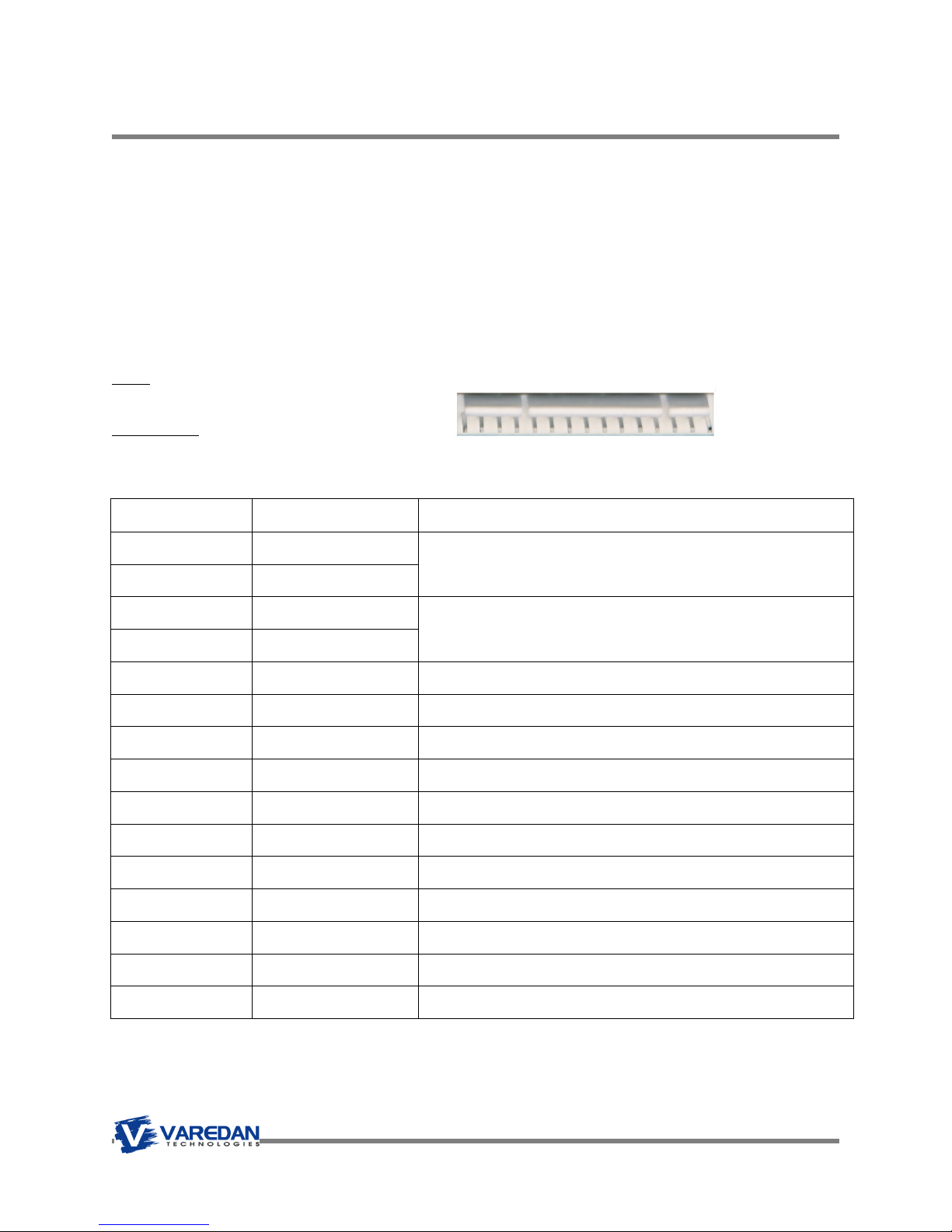
7.1 Main Signal Connector
There are 2 different connector options for the main signal connector, a 15-pin Molex or a high density
DB-26. The 15-pin Molex is typically used for 2-phase external current mode configurations. The signals
for each connector are shown below.
7.1.1 Main Signal Connector, 15-Pin Molex
Type: Molex 22-05-3151
Typical Mate
Molex: 22-01-3157
Digikey: 22-01-3157-ND
Pin Signal Name Description
1
2
DAC A+ Input
+/-10 VDC analog phase A command input
DAC A- Input
Pin 1
3
4
5
6
7
8
9
10
11
12
13
14
15
DAC B+Input
+/-10 VDC analog phase B command input
DAC B- Input
No Connect
Digital Ground
Current Monitor Output
Analog Ground Common for Analog DAC inputs.
No Connect
Enable
Fault Output
Digital Ground
Reset Input
Motor Temp Input Normally Closed thermal switch input from motor
No Connect
Common for logic level inputs and outputs.
Analog 0 to 10VDC output scaled to absolute value of maximum
phase current.
Logic level input to used to enable the amplifier. Active level is
programmable in software.
Logic level input from other amplifiers. Active level is programmable
in software
Common for logic level inputs and outputs.
Logic level input used to reset the amplifier. Active level is
programmable in software.
Page 19
VSA Series Product User Guide
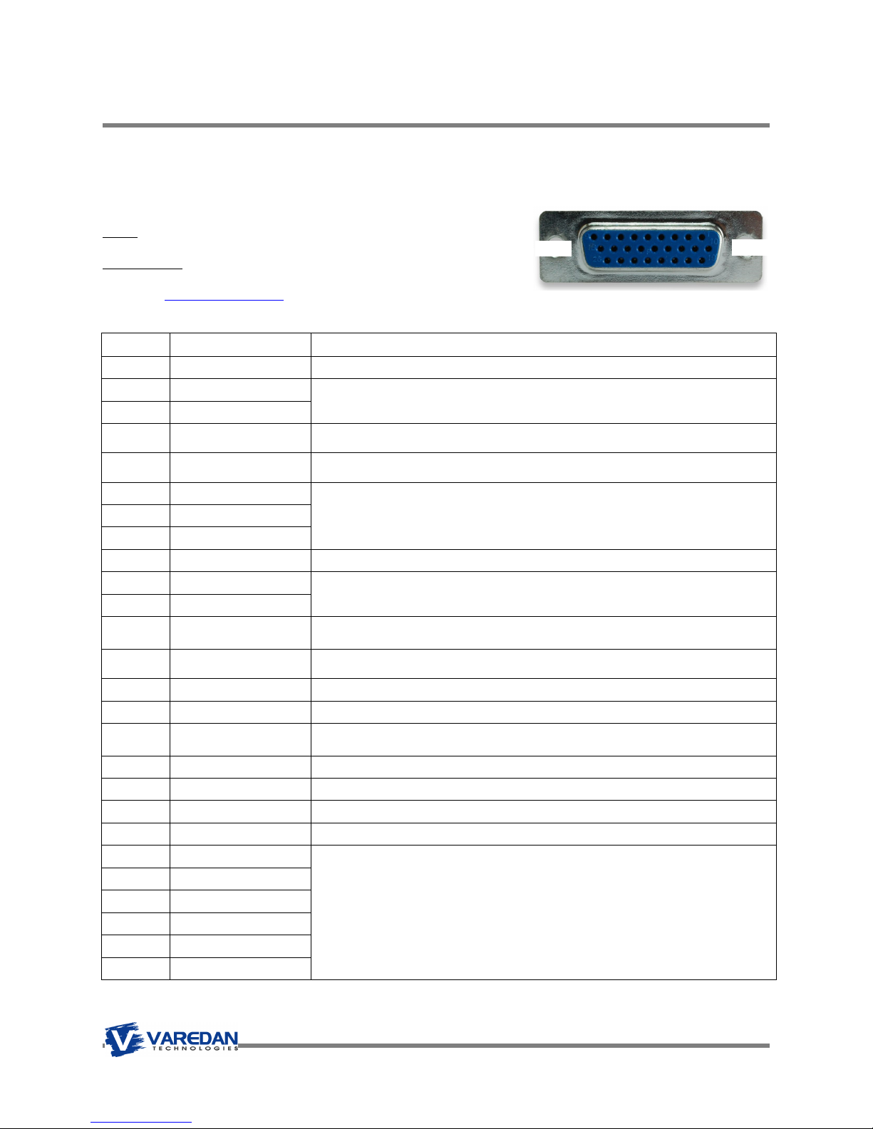
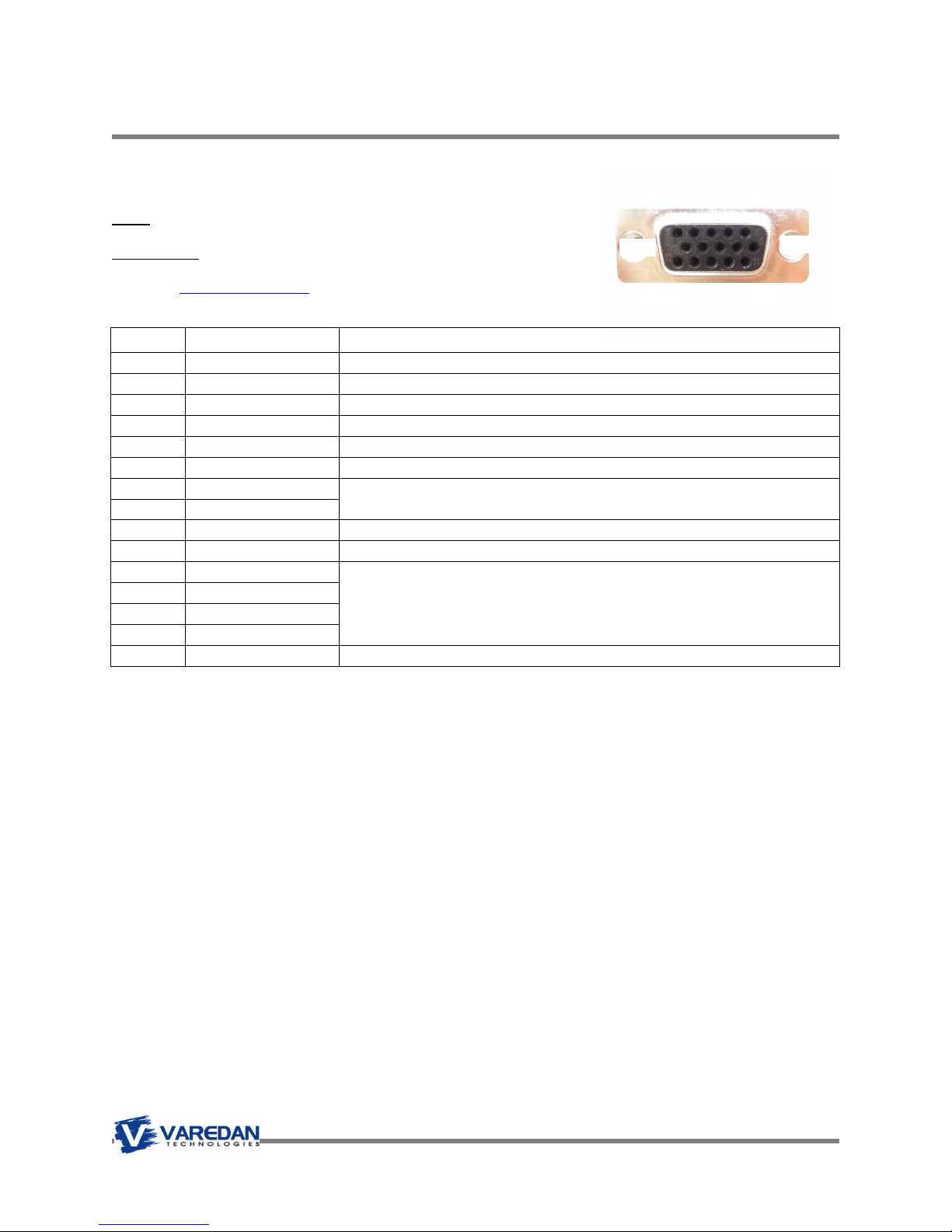
7.1.2 J1 Main Signal Connector DB-26HD
Type: DB-26HD Female
Typical Mate
Norcomp: 180-M26-103L031
Digikey: 180-M2631MN-ND
Pin Signal Name Description
1
2
3
4
5
6
7
8
9
10
11
12
13
14
15
16
17
18
19
20
21
22
23
24
25
26
Earth Ground Provides electrical connection to the chassis and heatsink of the amplifier
DAC A- Input
DAC A+ Input
Enable Input
Reset Input
User I/O 1
User I/O 2
User I/O 3
Fault Output Logic level input from other amplifiers. Active level is programmable in software
DAC B+Input
DAC B- Input
User I/O 4
High Speed Input
Current Monitor Output Analog 0 to 10VDC output scaled to absolute value of maximum phase current.
Digital Ground Common for logic level inputs and outputs.
High Current Output
Analog Ground Common for Analog DAC inputs.
Regen Clamp Output Logic level signal activated when measured bus voltage exceeds 350VDC.
Digital Ground Same as pin 15.
+5VDC Output +5VDC (200mA limit).
Encoder I- Output
Encoder I+ Output
Encoder B- Output
Encoder B+ Output
Encoder A- Output
Encoder A+ Output
+/-10 VDC analog command input used for analog velocity, analog
torque, or 2-phase sine input mode
Logic level input to used to enable the amplifier. Active level is programmable in
software.
Logic level input used to reset the amplifier. Active level is programmable in
software.
General purpose logic level signals, software programmable as inputs or
outputs.
+/-10 VDC analog command input used for 2-phase sine input mode or
as tachometer input in single-phase mode.
General purpose logic level signal, software programmable as input or
output.
Logic level input used to trigger hardware driven events in software. Can also be
used as a general purpose input.
Open drain output with 100mA drive capability. Programmable in
software.
Differential outputs driven from motor encoder inputs.
Pin 9
Pin 18
Pin 26
Pin 1
Pin 10
Pin 19
Page 20
VSA Series Product User Guide
7.2 J2 Motor Feedback Connector
Type: DB-15HD Female
Typical Mate
Norcomp: 180-M15-103L031
Digikey: 180-M1531MN-ND
Pin Signal Name Description
1
2
3
4
5
6
7
8
9
10
11
12
13
14
15
Notes: 1) +5vdc to J2-2 and J2-4 is internally fused at 250mA.
Earth Ground
+5VDC Output
Hall A Input
+5VDC Output1
Digital Ground
Hall B Input
Encoder I- Input
Encoder I+ Input
Hall C Input
Motor Temp. Switch
Encoder B- Input
Encoder B+ Input
Encoder A- Input
Encoder A+ Input
Digital Ground
1
Provides electrical connection to the chassis and heatsink of the amplifier
Provides encoder power, max 200mA.
Logic level input from hall sensors
Same as pin 2. Total current capacity for both pin 2 and pin 5 is 200mA
Common for logic level inputs and outputs.
Logic level input from hall sensors
Differential encoder channel input
Logic level input from hall sensors
Logic level or PTC input from motor temperature switch.
Differential encoder channel input
Common for logic level inputs and outputs.
Pin 10
Pin 15
Pin 5
Pin 1
Pin 6
Pin 11
Page 21
1 2 3 4 Pin 5
1 2 Pin 3
VSA Series Product User Guide
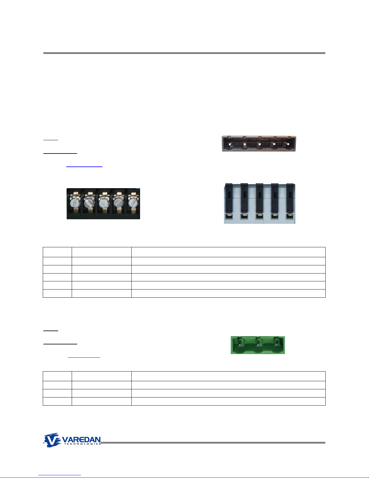
7.3 Motor and Power Connectors
The motor and power connections for the module can be one of three types; plug-in, screw terminal or
spring clamp, as shown below. The stand alone uses separate connectors for the motor and power
connections as shown in sections 7.3.2 and 7.3.3.
7.3.1 Module Motor and Power Connectors
Various connector options are available for the motor and power connectors for the module. The various
choices and their mates are shown below. All variations of connectors have a common pin out.
Type: Amphenol ELFH05410 5-position header, 0.300” spacing.
Typical Mate
Amphenol: ELFP05410
Digikey: APC1188-ND
Screw Terminals
Pin Signal Name Description
1
2
3
4
5
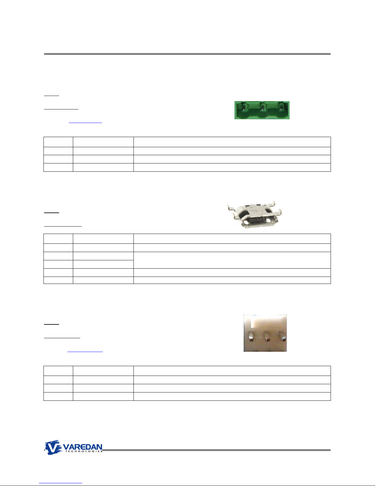
7.3.2 Motor Connector For Stand Alone Model (Front of Stand Alone Case)
Type: On Shore Technology EDSTLZ960/3
Typical Mate
On Shore Technology: EDZ960/3
Digikey: ED1734-ND
Motor Bus Voltage
Motor Bus Voltage
Motor Phase A
Motor Phase B
Motor Phase C
Pin Signal Name Description
1
2
3
Motor Phase A
Motor Phase B
Motor Phase C
Spring Clamp
DC bus voltage - input
DC bus voltage + input
Motor phase A connection
Motor phase B connection
Motor phase C connection
Note pin orientation compared to AC Connector
Motor phase A connection
Motor phase B connection
Motor phase C connection
Page 22
3 2 Pin 1
1 2 3
VSA Series Product User Guide
7.3.3 AC Power Connector For Stand Alone Model (Rear of Stand Alone Case)
Type: On Shore Technology EDSTLZ960/3
Typical Mate
On Shore Technology: EDZ960/3
Digikey: ED1734-ND
Pin Signal Name Description
Line
1
2
3
Neutral
Earth Ground
AC Line Input
AC Neutral Input
Chassis Ground
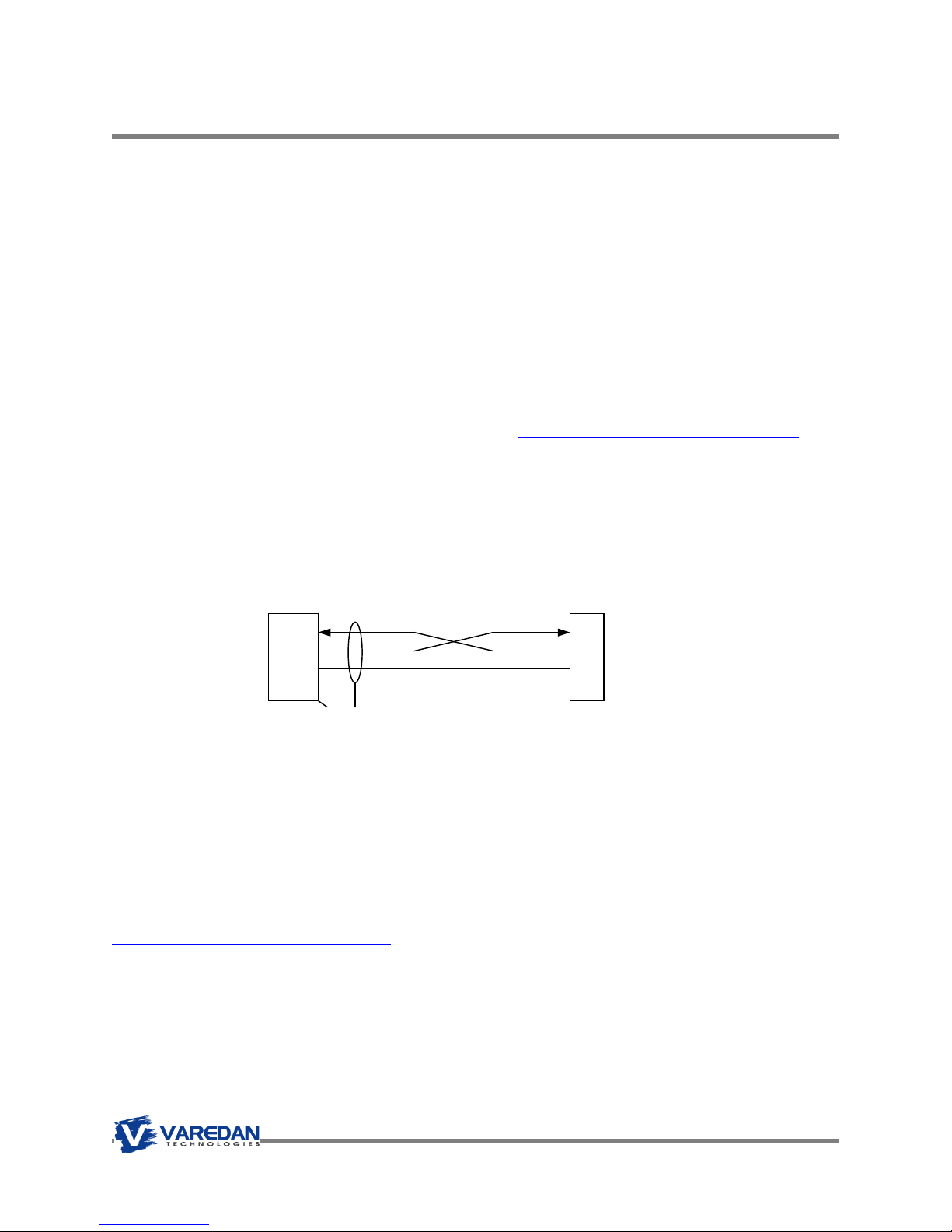
7.4 J4 USB Connection Micro USB-B (optional)
Type: USB Micro-B receptacle
Typical Mate: Standard USB micro-B cable
Pin Signal Name Description
1
2
3
4
5
5VDC
USB Minus
USB Plus
No Connect
Digital Ground
7.5 J5 RS-232 Serial Interface Connector (optional)
Type: Molex: 0022053031 3-position friction lock header.
Typical Mate:
Molex: 0010112033
Digikey: WM2602-ND
+5VDC from host computer
USB communication signals
Common
Pin Signal Name Description
1
2
3
RxD (input)
TxD(output)
Digital Ground
Rx input. Data from host computer, input to amplifier
Tx input. Data to host computer, output from amplifier
Common
Note pin orientation compared to Motor Connector
Page 23

VSA Series Product User Guide
8 Amplifier Input Power Requirements
8.1 Module DC Input Power
The VSA amplifier module requires a single DC input voltage in the range of 70-340 VDC (motor bus
voltage) connected to the B+ and B- inputs. All internal voltages are derived from this DC input voltage.
Note that B+ and B- are internally isolated.
8.2 Stand Alone AC Input Power
The VSA Stand Alone requires a single-phase AC line voltage input of between 80 and 230 VAC. Note
that this connection is to the rear of the case. Do not connect AC power to the J3 motor connector. A nonregulated linear power supply is used to derive the motor bus voltage from the AC line voltage. The
following function defines the resulting bus voltage given the AC line voltage:
Motor Bus Voltage (Volts DC) = AC Line Voltage * 1.414
Page 24
PC/Host
VSA
VSA Series Product User Guide
9 User Intefaces
9.1 Serial Interface
The VSA amplifier communicates with a host via a RS232 or USB connection at 115,200 baud.
Any “dumb terminal” serial communications program such as HyperTerminal can be used for
communications. The standard settings are 8 data bits, 1 stop bit, no parity and no hardware or software
handshaking.
In HyperTerminal, add a 100mS character delay by using the following steps:
Settings Emulation = ANSIW. ASCII Setup No boxes checked, 100msec delay,
HyperTerminal Note: When changing baud rates or establishing communication for the first time use the
call\disconnect and then call\call tab prior to cycling power to the amplifier.
A very good terminal emulator program can be found here: https://sites.google.com/site/terminalbpp/
That one is a bit more complex than HyperTerminal but it offers many more options and features than
Microsoft’s version.
9.1.1 RS232 Serial Interface
The amplifier can communicate with a host via RS-232 using a three wire DTE to DTE cross over serial
cable as shown below. Note that the J5 RS-232 interface pins (1 & 2) are disabled if the USB port is being
used, but the signal pins remain active.
RxD
TxD
Gnd
2
3
5
1
2
3
DB-9
Amplifier
Figure 8: Serial Data Cable Diagram
9.1.2 USB Interface
As an alternative to RS-232, USB can be used for communication. The VSA amplifier accepts a standard
USB Type MicroB connector.
The easiest way to use the USB interface is to establish a virtual com port (VCP) using the driver provided
by Future Technology Devices, Inc. which can be found at
http://www.ftdichip.com/Drivers/VCP.htm
This driver allows the USB port to be configured as a COM port by the operating system. Application
software can access the USB device in the same way as it would access a standard COM port with of the
same settings.
Be sure to set the baud rate for the VCP to 115,200 for Normal mode communication. When an active
USB cable is plugged into the USB port, the RS-232 communication on J5 is disabled.
Page 25

VSA Series Product User Guide
9.1.3 Communication Format
Once the host communication program is properly configured and the host cable is connected, apply
power to the VSA amplifier. The VSA amplifier should respond with the sign-on message which should
look like the following text in the terminal window. When the amplifier is ready to accept a new command,
the user prompt character “>” will be shown.
Commands can now be entered. The example below shows the reply from the CONFIG? command. It is
recommended to confirm the configuration of the amplifier to make sure it matches the motor and the
expected running parameters.
Figure
Once desired parameter values are found, use the WRITE command to save the changes. If a RESET is
issued before the WRITE command, any parameter changes will be lost and the amplifier will revert to the
last saved set of parameters.
In either RS-232 or USB modes, the following describes the command syntax and amplifier response
format:
Commands are entered using ASCII characters from the terminal or serial port. To enter a command with
a user entered data field, the command name followed by a “:” or “=” followed by the data for the
command, followed by Enter (carriage return) is used. As a minimum, all commands must be terminated
by the carriage return character (ASCII 13). The line feed (ASCII 10) is optional and is not used by the
amplifier.
A typical command has the following ASCII format. Control characters are shown in <>:
CONFIG?<Cr><Lf>
9: Serial Communications Interface
POLES=4<Cr><Lf>
All characters sent to the amplifier are echoed back. When the amplifier has accepted the command, the
prompt “>” is returned. Any invalid commands are ignored and the “Invalid Command” message is sent.
Page 26

D2
VSA Series Product User Guide
9.2 Pusbutton Switch S1
The pushbutton switch on the front panel (between the Encoder connector and Amplifier I/O connector) is
used to reset the amplifier. A quick press and release of the button should result in a full system reset. As
the amplifier comes out of reset (or power on), the 7-segment LED display will flash an “8” and then
indicate the operating mode as described later in this manual.
If the switch is held in and the power is applied (or cycled), the software version will be displayed
character by character on the 7-segment LED display, then the amplifier will enter normal operation. The
switch should be released as soon as the version number sequence starts on the LED display.
9.3 Firmware Programming Switch S2 & LED D2
S2 is a toggle switch used to put the DSP into programming mode. When this switch is in the down
position and the DSP is reset, the system will enter firmware programming mode and yellow LED D2,
which is adjacent to S2, will be on. When the DSP is in this mode normal amplifier operation is disabled.
For normal operation, this switch should be in the up position and LED D2 should be off. If the switch is
placed in the down position by accident, place the switch in the up position and reset the amplifier.
Programming mode is used to program the firmware in the DSP using the serial interface. See Appendix
B.
Figure 10. Program switch shown in normal operating position (up)
and LED D2 is shown in the off state.
Page 27

VSA Series Product User Guide
9.4 Status LED
The 7-segment LED display on the front panel shows the status of the amplifier in real-time. The amplifier
should display an “8” and then a “C” when first powered or after a reset in the disabled state with no
errors. The amplifier should display “0” when enabled. When an error is detected, the amplifier is disabled
and an error code is shown on the display.
The following table lists the front panel LED display codes and their meaning. If multiple errors are
present, the display will cycle through all the error codes, displaying each for ½ second. Most errors can
be reset by either pressing the front panel pushbutton switch or cycling power to the unit. Some errors
cannot be fixed in the field. Please contact the factor for assistance with any errors that do not clear after
a reset.
LED
Code
1
External fault Input is active
2
Non-volatile memory error
3
I2C internal bus error
4
Encoder phase error
5
Not used
6
+/-15v internal bias power supply error
7
Offset reference internal supply error
8
Power on reset (shows briefly following reset)
9
Not used
A
Logic internal power supply error
b
Bus over voltage
C
Disabled (normal message)
C
Checksum memory error (lower case c)
E
Hall error (only active when halls are enabled)
F
PWM over current fault
H
Heatsink over temperature
h
Motor over temperature input active
L
I2T Over current fault
O
Enabled (normal message)
o
Motor over speed (only active in velocity or position mode)
.
Decimal point indicates current is exceeding current limit set point
Description
Page 28

VSA Series Product User Guide
10 Protection Functions
The amplifier has a number of built-in protective functions that disable the amplifier in the event of a
sensed fault. The fault conditions are explained in the following sections.
10.1 I2T Over Current Protection
This function protects the amplifier and motor in the event of an over current condition. This algorithm
closely simulates the heating effect of current through the windings of a motor. The settings for this
function are user programmable within the limits of the amplifier and provide protection for both
continuous and peak over current conditions over time. This algorithm provides a trip time that is
proportional to the amount of over current, so for higher values, the amplifier will trip faster than lower
values.
Once the sensed motor current exceeds the CcLimit trip value, the DSP begins accumulating time. If the
sensed current remains above the CcLimit value, the amplifier will shut down, or trip, in the amount time
based on the following formulas. If the sensed current falls below the CcLimt, the accumulator decreases
until it reaches 0. If the amplifier trips due to the timer reaching the time-out value, an I2T Error (LED code
“L”) is reported.
The values that determine the limits for over current protection are as follows:
CcLimit = Allowable continuous current limit in amps. Set using the CCLIMIT command.
PkLimit = Allowable peak current limit in amps. Set using the PKLIMIT command.
PkTime = Allowable peak current time duration in seconds. Set using the PKTIME command.
The calculation for I2T over current is based on 2 equations:
Equation 1: I2T Limit = ((PkLimit2 - CcLimit2) * PkTime) in amp2*seconds
Equation 2: Trip time in Seconds = I2T Limit / (Sensed Current2 - CcLimit2)
Equation 1 is calculated after reset or if any of the above 3 current values are changed
Equation 2 is continually performed using the sensed current to determine if a trip condition exists.
For a given set of over current parameters and sensed current, the trip time can be calculated:
Example:
CcLimit = 5A
PkLimit = 15A
PkTime = 0.5 seconds
If Sensed Current = 18A (Slightly greater than PkLimit so trip time should be less than PkTime)
From Equation 1) I2T Limit = (152A - 52A) * 0.5 sec
=
100 amp2 * seconds
From Equation 2) Trip Time = 100 amp2 * seconds / (182A - 52A) = 0.344 seconds
If Sensed Current = 10A
From Equation 2) Trip Time = 100 amp2 * seconds / (102A - 52A) = 1.33 seconds
Page 29

VSA Series Product User Guide
10.2 Internal Protection
The amplifier has multiple internal protective functions that check for error conditions. If an error is found,
the amplifier is disabled and the appropriate error code(s) is displayed on the 7-segment LED and
reported over the serial interface. The parameters for these internal errors are fixed at the factory and are
not user programmable.
LED Fault Description
Error Code
1
2
3
4
5
6
7
8
9
A
b
d
c
E
F
H
h
L
O
o
. Decimal Point
(blank) No display
1 - If a reset or power cycle sequence does not correct error, amplifier maybe damaged and will need to
be returned to factory for further troubleshooting and repair.
Internal Reference Error
Motor Over Temperature
Condition of Fault Cleared/Corrected By
External Fault
NVM Error
I2C Error
Encoder Phase Error
Not Used
Internal Bias Error
None - Power on reset
Not Used
Internal Logic Power
Error
Bus Over Voltage
Disabled
Checksum
Hall Error
PWM Fault
Amplifier Over
Temperature
I2T Over Current Fault
Enabled
Over Speed
External fault input is
active
Internal memory error Reset1
Internal bus error Reset1
DSP detected illegal
encoder state
Internal power supply fault Reset1
Internal power supply fault Reset1
Normal, displays briefly
after reset
Internal power supply fault Reset1
External Bus > 340 VDC Lower bus voltage
Normal message in
disabled state
Internal memory error Reset1
Hall Sensor inputs are all
1's or 0's (illegal condition)
Internal PWM stage power
fault
Heatsink temperature >
70°C
Motor Temperature switch
active
Over current trip condition Reset. Reduce current, change I2T
Normal message in
enabled state
Motor speed > Overspeed
setting
I2T Over Current is about
to trip
Amplifier may be in
firmware update mode
Set Fault input inactive
Reset. Check encoder output and/or
wiring and encoder power
Check reset input or reset switch if
stuck on "8"
Check hall wiring and/or hall sensors
and encoder power
Reset1
Disable amplifier, provide adequate
cooling, reduce current
Disable amplifier, use less power, use
bigger motor
settings
Reset. Reduce speed. Change Over
Speed setting.
Reduce current, change I2T settings
Check programming switch (should be
up for normal operation). Cycle power.
Page 30

VSA Series Product User Guide
11 Modes of Operation
This amplifier is basically a device that outputs and controls current (torque in the motor) to its motor
phase connections in either a single-phase or three-phase configuration. How that current gets
commanded and where the command comes from is determined by the amplifier’s mode of operation. In
all modes of operation, a “command current” must come from somewhere in the system. Whether the
command current comes from an external controller or from inside the amplifier is determined by the
mode of operation. The DSP in this amplifier uses this current command to internally close the current
loop in each motor phase using pulse-width modulation (PWM) by allowing more or less current to flow
through the output transistors.
For modes that use an external command current, the command current can come from one of two
sources; the analog DAC input(s) or as a serial command from the user interface.
For modes that generate the current command internal to the amplifier as in the case of velocity or
position modes, a higher-level control loop is used to generate the command. For velocity mode, the
current command comes from the output of the velocity loop. The command for the velocity loop comes
from either the analog DAC input, or as a serial command from the user interface. For position mode, the
current command still comes from the velocity loop, but the velocity command now comes from the
internal position loop. The position loop command comes from either an external source over the serial
interface, or from the internal trajectory amplifier when the amplifier is commanded to move to a specific
position.
Operating Mode
Single-
Phase
modes
Three-
Phase
modes
Each of the modes is explained in detail in the following sections. For each of the modes, the serial
commands used to establish the mode of operation are given, followed by the commands that are active
in that particular mode.
The command used to establish the operating mode is AMPMODE. Use of this command will be
explained in the following sections.
Single phase mode torque
Single phase velocity mode
Single phase position mode
2-Phase Sine Mode
Three phase torque mode
Three phase velocity mode
Three phase position mode
1
2
3
4
5
6
7
Ampmode
Analog Input
Digital Input
Commutation
Velocity Control
Position Control
Page 31
Σ
CPGAIN
Σ
Σ
CPGAIN
Σ
VSA Series Product User Guide
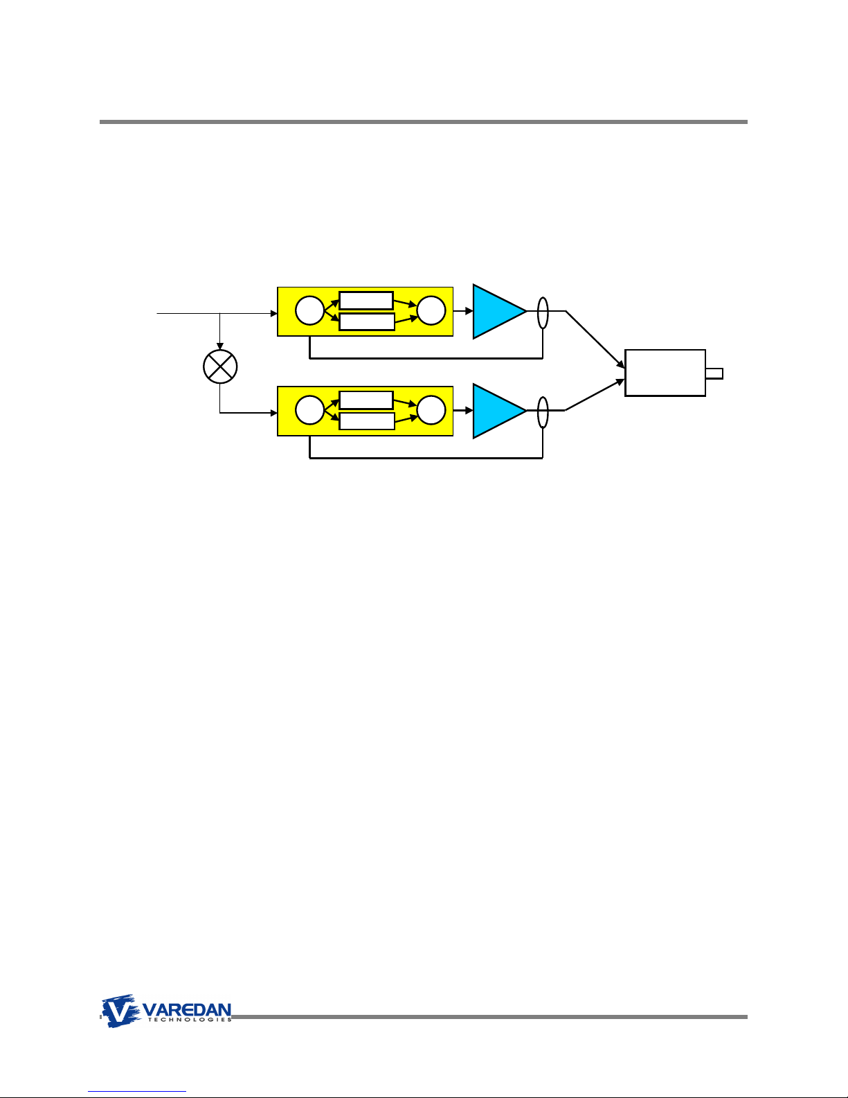
11.1 Single-Phase or Brush Motor Torque Mode
In this mode the output current is proportional to the applied +/-10 VDC analog voltage or serial
command current. The amplifier controls the current in phase A with the positive current command value
and the current in phase B with the inverse or negative current command value. The current command
comes from either an external amplifier or from the open loop OL command over the serial interface.
11.1.1 Single Phase Torque Mode Settings
To put the amplifier in this mode, use the following settings (with the amplifier disabled):
AMPMODE=1
To change the current loop PI parameters, use the following commands:
CPGAIN, CIGAIN, CINTLIMIT
To set the transconductance (volts to amps), use the following command:
ANALOGSCALE=2 (Sets gain for 1 volt input = 2 amps out.)
The amplifier can now be enabled using either the serial command EN or by setting the hardware Enable
input active. To use the hardware Enable input and set the active state of the Enable input, use the
following commands:
EXTENABLE=1 Use hardware Enable input as source for the amplifier enable
ENABLELEVEL=0 Set the Enable active state to 0 (low for enable)
WRITE Save these settings in NVM
Torque
Command
-1
Phase A Current Loop
+
CIGAIN
-
Feedback Current
Phase B Current Loop
+
CIGAIN
-
Feedback Current
+
+
+
+
PWM
A
Motor
PWM
B
Page 32
Commutation
Σ
VIGAIN
VPGAIN
Σ
VDGAIN
VSA Series Product User Guide
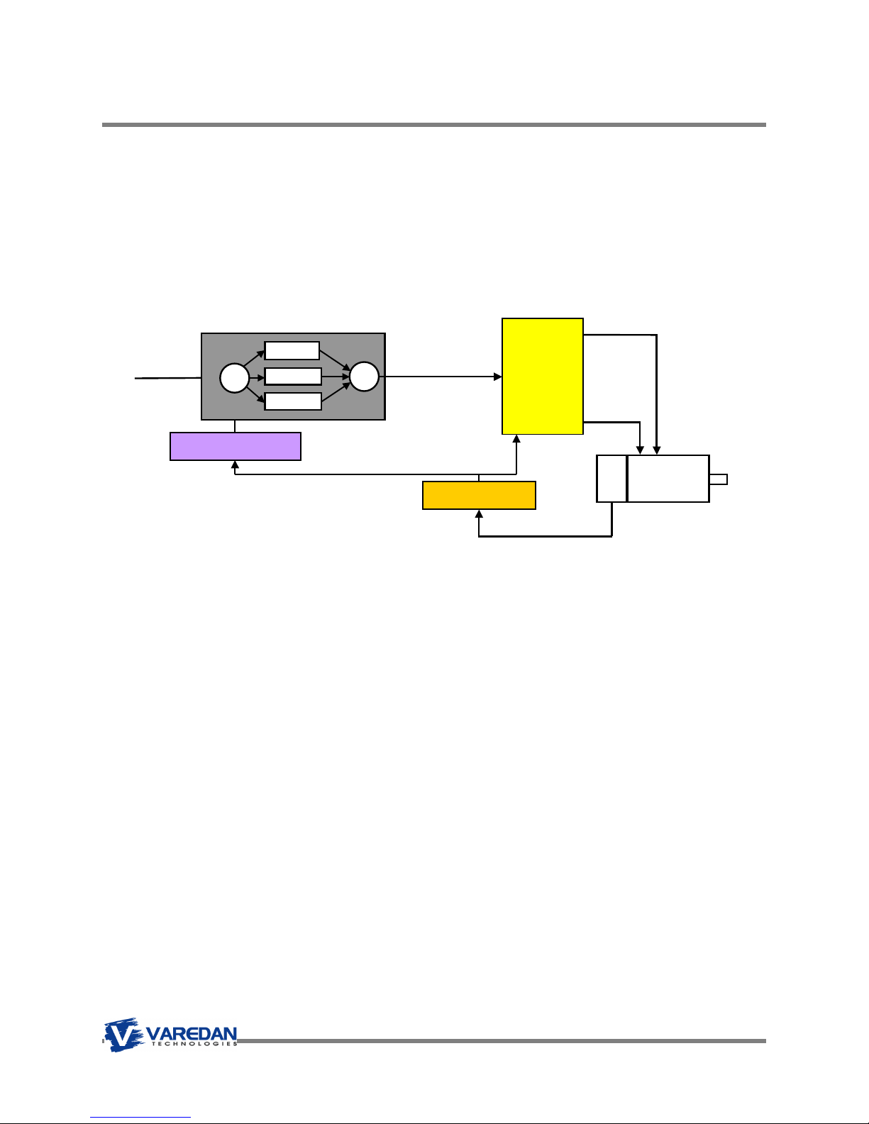
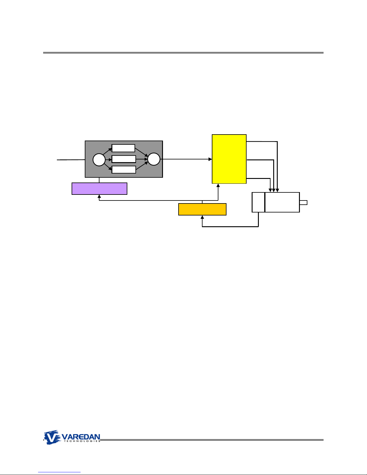
11.2 Single-Phase Veolcity Mode
In this mode, the amplifier uses either a motor mounted encoder or a tachometer to provide speed control
of the motor. The motor speed is controlled by the amplifier’s PID velocity loop, which in turn provides the
current (torque) command to the current loops. The velocity command can come from either the DAC A
analog input in the form of a +/-10 VDC command voltage, where +10v is full scale velocity or from the
Speed=x command from the serial interface (x can be any number between 0 and 30000 rpm, depending
of course on the motor and encoder or tachometer’s capabilities). The direction of rotation for a given
input polarity can be set using the CW or CCW commands.
Velocity
Command
11.2.1 Single-Phase Velocity Mode Settings
To put the amplifier in this mode, use the following settings (with the amplifier disabled):
AMPMODE=2
To change the current loop PI parameters, use the following commands:
CPGAIN, CIGAIN, CINTLIMIT
To change the velocity loop PID parameters, use the following commands:
VPGAIN, VIGAIN, VDGAIN, VINTLIMIT
The default input is to use the analog DAC voltage as the velocity command reference. The VELSCALE
command sets the relationship of input volts to motor RPM as follows:
VELSCALE=200 (Set gain for 1 volts = 200 RPM, or 10v = 2000 RPM.)
The amplifier can now be enabled using either the serial command EN or by setting the hardware Enable
input active. To use the hardware Enable input and set the active state of the Enable input, use the
following commands:
EXTENABLE=1 Use hardware Enable input as source for the amplifier enable
ENABLELEVEL=0 Set the Enable active state to 0 (low for enable)
WRITE Save these settings in NVM
Speed Calculation
Velocity PID Loop
+
-
+
+
+
Torque
Command
Motor Position
Current
Loops
And
Power
Stage
FB
Motor
Page 33
Σ
CPGAIN
Σ
Σ
CPGAIN
Σ
DAC A
DAC B
Σ
CPGAIN
Σ
VSA Series Product User Guide
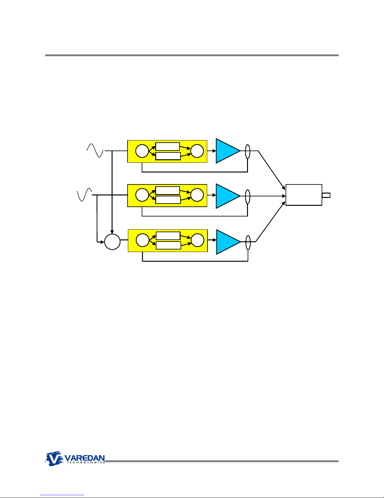
11.3 2-Phase Sine Mode (External Sine Commutation)
In this mode, an external motion controller provides commutation and supplies two current commands
(sine waves 120 degrees apart) to the DAC A and DAC B inputs. The amplifier internally generates the
current command for the third phase from the negative sum of the supplied phases C = -(A + B). The
amplifier closes all 3 current loops internally. The output current is proportional to the applied +/-10 VDC
analog voltage. No feedback from the motor to the amplifier is required since commutation is not
performed in the amplifier.
2-Phase Sine
commands
from external
amplifier
11.3.1.1 2-Phase Sine Mode Settings
To put the amplifier in this mode, use the following settings (with the amplifier disabled):
AMPMODE=3
To change the current loop PI parameters, use the following commands:
CPGAIN, CIGAIN, CINTLIMIT
To set the transconductance (volts to amps), use the following command:
ANALOGSCALE=2 (Sets gain for 1 volt input = 2 amps out.)
The amplifier can now be enabled using either the serial command EN or by setting the hardware Enable
input active. To use the hardware Enable input and set the active state of the Enable input, use the
following commands:
EXTENABLE=1 Use hardware Enable input as source for the amplifier enable
ENABLELEVEL=0 Set the Enable active state to 0 (low for enable)
WRITE Save these settings in NVM
+
-Σ
+
Phase A Current Loop
+
CIGAIN
-
Feedback Current
Phase B Current Loop
+
CIGAIN
-
Feedback Current
Phase C Current Loop
+
CIGAIN
-
Feedback Current
+
PWM
A
+
+
+
PWM
B
Motor
+
PWM
+
C
Page 34
Loo
k up
VSA Series Product User Guide
11.4 Three-Phase Torque Mode
In this mode, the amplifier uses the motor’s encoder to provide commutation. The current in the motor is
controlled by the amplifier’s PI current loops and is proportional to the current (torque) command. The
torque command can come from either the DAC A analog input in the form of a +/-10 VDC command
voltage, where +10v is full scale (peak) positive current or from the OL=x command from the serial
interface (x can be any number between 0.00 and 10.00 representing an equivalent input voltage).
Torque
Command
Sine wave
Motor Position
11.4.1 Three-Phase Torque Mode Settings
To put the amplifier in this mode, use the following settings (with the amplifier disabled):
AMPMODE=4
Setup the motor and encoder parameters:
ENCODERCOUNT= 1000 Setting for 1000 line encoder
ENCODERTYPE=S Single ended encoder
POLES=4 Four pole motor
To change the current loop PI parameters, use the following commands:
CPGAIN, CIGAIN, CINTLIMIT
The default input is to use the analog DAC voltage as the torque command reference. To use the open
loop software value, use the OL command with the equivalent DAC voltage as the data.
Example: OL=2.55 Sets the torque command to 2.55 volts, causing 2.55 amps to go to the motor.
To set the transconductance (volts to amps), use the following command:
ANALOGSCALE=2 (Sets gain for 1 volt input = 2 amps out.)
The amplifier can now be enabled using either the serial command EN or by setting the hardware Enable
input active. To use the hardware Enable input and set the active state of the Enable input, use the
following commands:
EXTENABLE=1 Use hardware Enable input as source for the amplifier enable
ENABLELEVEL=0 Set the Enable active state to 0 (low for enable)
WRITE Save these settings in NVM
Phase A Current
Phase B Current
Phase C Current
FB
Motor
Page 35
Commutation
Σ
VIGAIN
VPGAIN
Σ
VDGAIN
VSA Series Product User Guide
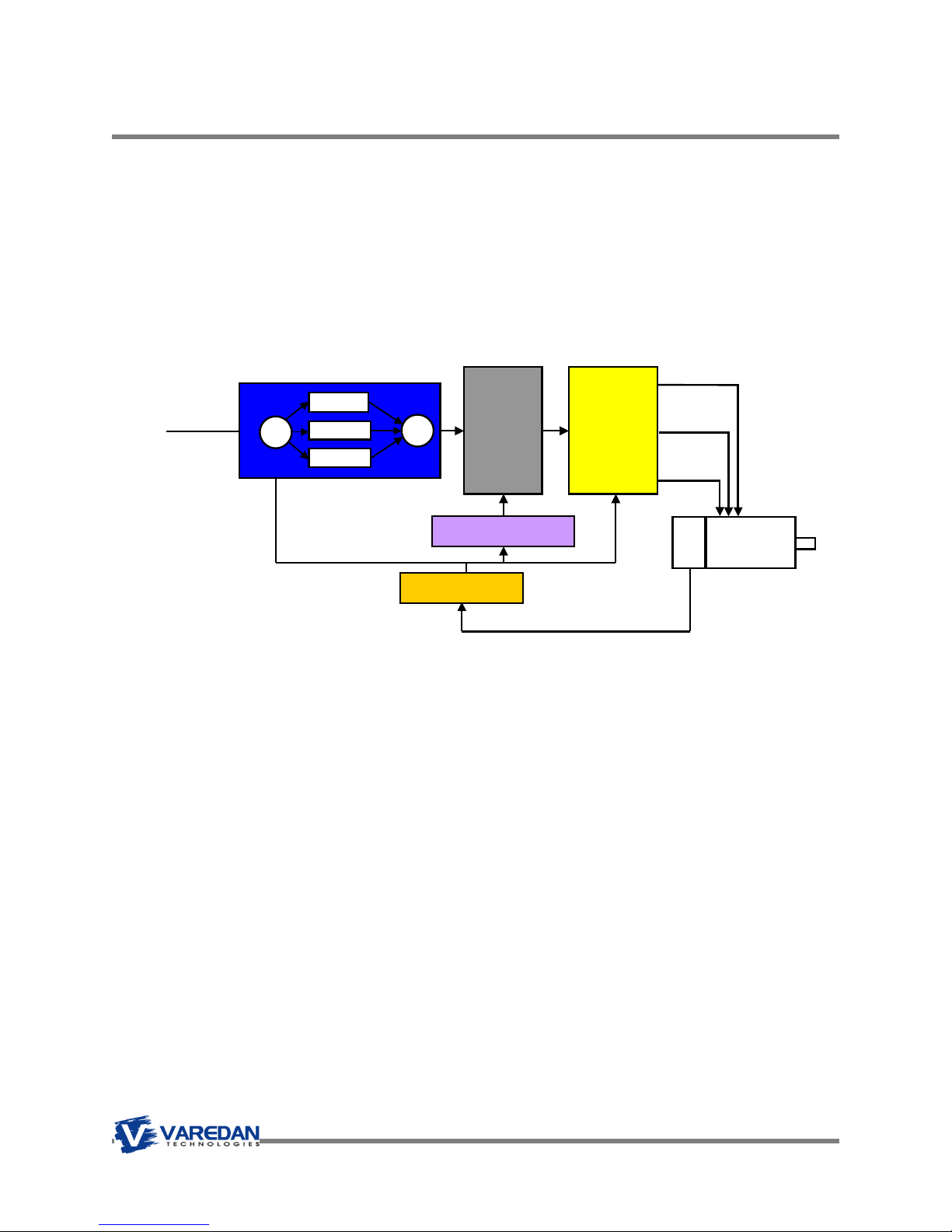
11.5 Three-Phase Veolcity Mode
In this mode, the amplifier uses the motor’s encoder to provide commutation and speed control. The
motor speed is controlled by the amplifier’s PID velocity loop, which in turn provides the current (torque)
command to the current loops. The velocity command can come from either the DAC A analog input in the
form of a +/-10 VDC command voltage, where +10v is full scale velocity or from the Speed=x command
from the serial interface (x can be any number between 0 and 30000 rpm, depending of course on the
motor and encoder capabilities). The direction of rotation for a given input polarity can be set using the
CW or CCW commands.
Velocity
Command
11.5.1 Three-Phase Velocity Mode Settings
To put the amplifier in this mode, use the following settings (with the amplifier disabled):
AMPMODE=5
To change the current loop PI parameters, use the following commands:
CPGAIN, CIGAIN, CINTLIMIT
To change the velocity loop PID parameters, use the following commands:
VPGAIN, VIGAIN, VDGAIN, VINTLIMIT
The default input is to use the analog DAC voltage as the velocity command reference. The VELSCALE
command sets the relationship of input volts to motor RPM as follows:
VELSCALE=200 (Set gain for 1 volts = 200 RPM, or 10v = 2000 RPM.)
The amplifier can now be enabled using either the serial command EN or by setting the hardware Enable
input active. To use the hardware Enable input and set the active state of the Enable input, use the
following commands:
EXTENABLE=1 Use hardware Enable input as source for the amplifier enable
ENABLELEVEL=0 Set the Enable active state to 0 (low for enable)
WRITE Save these settings in NVM
Speed Calculation
Velocity PID Loop
+
-
+
+
Torque
Command
+
Motor Position
Current
Loops
And
Power
Stage
FB
Motor
Page 36
Σ
PPGAIN
Σ
PDGAIN
Commutation
VSA Series Product User Guide
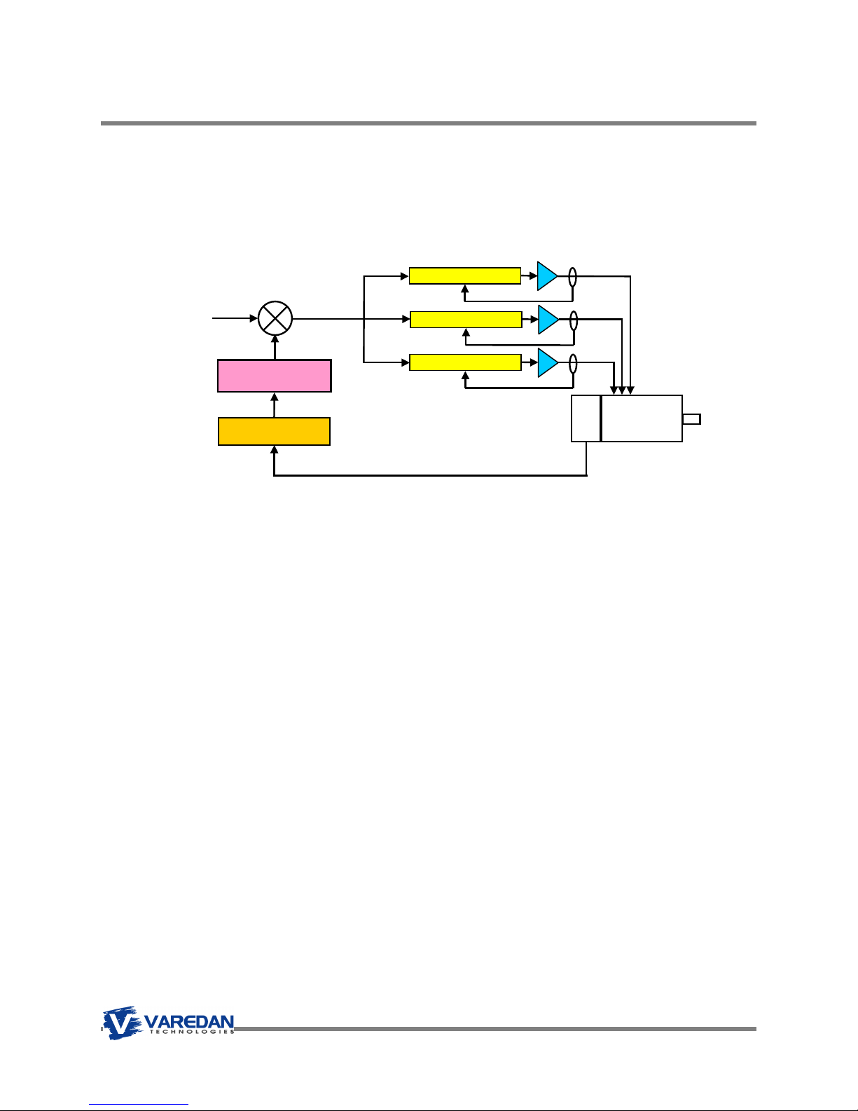
11.6 Three-Phase Position Mode
In this mode, the amplifier uses the motor’s encoder to provide commutation and position control. The
motor position is controlled by the amplifier’s position PID loop, which in turn provides the velocity
command and current (torque) commands to the internal loops. The position command comes from the
serial interface in the form of a GOTO=x command. The internal trajectory generator provides the ramping
and velocity control during the move. Once the motor reaches the end position, the motor holds within +/-1
encoder count at that position.
Position
Command
Position PID Loop
+
-
PIGAIN
+
+
Velocity
PID
Loop
+
Speed Calculation
Current
Loops
And
Power
Stage
FB
Motor
Motor Position
11.6.1 Three-Phase Position Mode Settings
To put the amplifier in this mode, use the following settings (with the amplifier disabled):
AMPMODE=6
To change the current loop PI parameters, use the following commands:
CPGAIN, CIGAIN, CINTLIMIT
To change the velocity loop PID parameters, use the following commands:
VPGAIN, VIGAIN, VDGAIN, VINTLIMIT
To change the position loop PID parameters, use the following commands:
PPGAIN, PIGAIN, PDGAIN, PINTLIMIT
WRITE Save these settings in NVM
The amplifier can now be used to position the motor using the GOTO=x command, where x = the deisred
position.
GOTO=1000 Moves to position 1000 and holds position
Page 37

VSA Series Product User Guide
11.7 Three-Phase Commutation Phase Finding
For three phase modes (torque, velocity and position), the motor will perform an initial phase finding when
first enabled. The type of algorithm used for the phase finding is determined by the TYPE=n command.
When n is set to 6, the amplifier uses the motor mounted halls to determine the initial phasing for the
motor, and then switches over to full sine commutation after the first hall transition. Using Type 6 mode
will result in no motor movement other than what’s commanded.
When n is set to 7, the amplifier requires only the encoder (no halls) for commutation. The downside is
that there is movement of the motor during this phase finding sequence. This phase finding sequence is
only performed once after power on reset. The value for COMCURRENT is used to determine the amount
of current to apply to the motor to perform the initial phase finding.
11.8 Three Phase Mode Modulation
When using sinusoidal commutation modes (Amp modes 5, 6 and 7), the user can select the type of
PWM modulation performed by the DSP. The 2 choices are Space Vector (a.k.a. Field Oriented Control
FOC) or Traditional Sinusoidal. The SVENABLE command selects which type is used.
11.8.1 Space Vector or Field Oriented Control
Space vector modulation is a PWM control algorithm used for multi-phase AC generation (as in the case
of driving brushless servo motors), in which the available bus voltage is used more efficiently than
traditional sinusoidal PWM modulation.
In the space vector PWM technique, there is 15% gain in motor voltage as compared to traditional analog
sinusoidal PWM. There is also a reduction in the harmonics generated by the output devices due the
switching methods used. What this means is that for a given bus voltage, the motor will be able to run
faster using FOC modulation.
While the resulting current control is sinusoidal, the motor voltages are non-sinusoidal and will have a
“flattened” top when displayed on an oscilloscope.
11.9 Traditional Sinusoidal Modulation
With traditional sinusoidal modulation, motor voltages are controlled on an individual basis using a look up
table with stored sine values. This technique results in smooth motor movement across the whole speed
range. The disadvantage is that it uses the motor bus voltage less efficiently than with space vector
modulation.
We make this modulation scheme available in our amplifiers for those system designers that have
always used sinusoidal modulation and do not want to change to space vector modulation.
Page 38

VSA Series Product User Guide
12 Command List
The following commands can be entered over the serial interface and are not case sensitive. When a
string of n’s (nnnnn) are shown the data is an integer value. When a string of f’s (ffff) are shown the data
is a floating point value. When a string of c’s (ccc) are shown, a character value is required (ex:
HALLS:ABC). For numeric values, the user interface does not care if more or less characters are entered.
Leading “0’s” on numbers are not needed. Not all commands apply to all operating modes. Note: The “:”
and “=” can be used interchangeably to separate a command from the input parameter data.
ACCEL:nnnnn Set this value to the desired acceleration rate in RPM/sec with a range from 1
to 40000 RPM/Sec.
ACCEL? Replies with the currently set acceleration rate in RPM/sec
ALARMRESET Resets faults in the amplifier.
AMPMODE:n Sets the operating mode of the amplifier. Amplifier must be disabled to
change modes.
AmpMode Description
1 Single-phase current mode
2 Single-phase velocity mode
3 Single-phase position mode
4 Three-phase external commutation mode
5 Three-phase current mode
6 Three-phase velocity mode
7 Three-phase position mode
AMPMODE? Display the mode setting.
ANALOGIN Sets the analog input as the command source for torque or velocity modes.
The External Enable Input is used to enable the system. CW and CCW
control the rotation direction for the sign of the input voltage. The default is
CW for a positive analog input voltage.
ANALOGOUT Disables the analog input as the command source.
ANALOGSCALE:f.f Used to scale the transconductance (volts in to amps out) for torque modes.
Default is 1 for 1VDC = 1Amp. The floating-point range is 0 – 10 (volts per
amp). Ex. ANALOGSCALE= 2.0 sets the scaling to 1 volt in = 2 amps out.
ANGLE:nnn Sets the motor commutation angle from 1 – 359 degrees. Also see OFFSET.
ATSPDLVL:n Sets the active state for the At Speed Output. Range is 0 or 1.
ATSPD? Replies with YES if the spindle is running within the at speed range. Also see
the LOKDLY and ATSPDLVL commands.
Page 39

VSA Series Product User Guide
CCLIMIT:nn Sets the allowable continuous motor current. Range is 0 to continuous rated
current, depending on model. When the sensed motor current exceeds this
setting, the over current protection algorithm begins timing for a trip.
CCW Sets the commanded spindle direction to Counter-Clockwise. For analog
input modes this command will set the spindle direction to CCW for a positive
input voltage.
CDGAIN:nnnn Current loop derivative gain. Range is 0-32767.
CIGAIN:nnnn Current loop integral gain. Range is 0-32767.
CPGAIN:nnnn Current loop proportional gain. Range is 0-32767.
CINTLIMIT:nnnnnn Current loop Integration gain limit. 0 – 500,000. Used to “shape” the initial
current profile. A lower value will “roll on” the current while a higher value will
be more “snappy.
CL Sets closed loop mode. (Only needed if OL is used for Open Loop).
COMCURRENT:nn Sets the commutation current when using Type=7. Range is 0-10 (amps).
COMMUTATION? Replies with a 6 (Hall Mode) or a 7 (Encoder / Sine) representing the
presently set commutation mode.
CONFIG? Replies with a brief listing of the amplifier configuration. Note: This is a legacy
command. Please use the DUMPALL command to view all parameters.
Drive parameters:
Speed: 5000
Torque: 100
Direction: CW
Acceleration: 5000
Acceleration: on
Top speed: 25000
Stop Speed: 10
Frequency: internal
System Control: remote
Polecount: 8
Encoder Linecount: 1024
Commutation Type: 7
Angle: 0 Angle Offset: 0
Deceleration: 2000
Encoder Type: Differential
BNC Output: all
Feedback Divisor: 1
CW Sets the commanded spindle direction to Clockwise. For analog input modes
this command will set the spindle direction to CW for a positive input voltage.
DECEL:nnnnn Set this value to the desired deceleration rate in RPM/sec with a range from 1
to 40000 RPM/Sec.
Page 40

VSA Series Product User Guide
DEFAULTS Do not use this command unless instructed to do so by the factory.
Important calibration values are cleared by this command.
Sets the factory defaults for all parameters as shown below. Note that the
Ampmode is set to 2-phase sine after executing this command. Values are
NOT saved to NVM after this command is issued.
ACCEL=3000 (set acceleration to 3000 rpm/s2)
AMPMODE=4 (2-phase sine mode)
ANALOGOUT (disable analog command)
ANALOGSCALE=1 (set analog input scaling to 1v)
ANGLE (phase advance angle = 0)
ATSPDLVL=0 (set At Speed Level output to 0 for active state)
CCLIMIT=4 (set continuous current limit to 4 amps)
CDGAIN=0 (set current loop d gain = 0)
CIGAIN=10 (set current loop i gain = 10)
CINTLIMIT=1000 (current loop integrator limit=1000)
CPGAIN=10 (set current loop p gain =10)
CW (default run direction for + command)
DECEL=3000 (set acceleration to 3000 rpm/s2)
DISFAULTS=FFF0
ENABLELEVEL=0 (set active enable level to 0)
ENCODERCOUNT=1000 (set encoder line count to 1000 lines)
ENCODERTYPE=S (Single-ended encoder)
EXTENABLE=0 (disable external enable input)
JERK=0 (disable jerk)
MAPIO0=0 (map user I/O 0 as input)
MAPIO1=0 (map user I/O 1 as input)
MAPIO2=0 (map user I/O 2 as input)
MAPIO3=0 (map user I/O 3 as input)
MINSPDOUT (disable minimum external frequency clock speed)
NOSWAP (disable internal swapping of encoder channels)
OFFSET=0 (hall offset angle = 0)
OVERSPEED=21000 (set overspeed fault to 21000 rpm)
PDGAIN=9 (set position d gain = 9)
PIGAIN=200 (set position i gain = 200)
PKLIMIT=10 (set peak current limit to 10 amps)
PKTIME=1 (set peak current time to 1 second)
POLES=4 (set motor poles=4)
PPGAIN=200 (set position p gain = 200)
RAMPIN (enable internal trajectory generator)
SPEED=1000 (set target run speed to 1000 rpm)
STOPS=1 (set stop speed to 1 rpm)
TOPSPEED=5000 (set topspeed limit to 5000 rpm)
TORQUE=100 (set maximum allowed motor torque to 100%)
TYPE=7 (Encoder startup commutation)
VDGAN=0 (set velocity d gain = 0)
VIGAIN=10 (set velocity i gain = 10)
VINTLIMIT=1000 (velocity loop integrator limit=1000)
VPGAIN=10 (set velocity p gain =10)
ZSPDLVL=1 (set Zero Speed Level output to 1 for active state)
(mask encoder phasing, overspeed, motor overtemp and hall
faults)
Page 41

VSA Series Product User Guide
DIR? Returns the actual motor direction as “CW” or “CCW”.
DIS Disables the amplifier (kills motor power). No deceleration is performed.
DISABLE Same as DIS.
DISFAULTS:nnnn Creates a bit mask for maskable faults within the amplifier. See DISFAULTS?
for the bit definitions.
DISFAULTS? Displays the DISFAULTS value and lists the enable/disable state for each
fault.
A “1” in a bit position indicates a fault is disabled.
2 Over Speed
3 Encoder Phasing
4 NVM (internal non-volatile memory)
5 Internal Logic Power Supply
6 Bus Over Voltage
7 ROM Checksum
8 I2C (Over Current Fault)
9 External Error (Fault Input Active)
10 PWM Fault (Internal Power Stage)
11 Amplifier Over Temperature
12 Instantaneous Over Current
13 Reserved
14 Reserved
Bit Fault
0 Motor Over Temperature
1 Hall Sequence
15 Reserved
Note that the amplifier does not allow all errors to be masked. The following
bits are always set to 0 by the amplifier: Bits 11, 10, 7, 5, and 4.
DUMPALL Lists all parameter names and settings in a format that can be copied and
saved into a text file for amplifier backup. See appendix A for more
information on the data. Note: The data shown by this command will vary
depending on the Ampmode setting. Only data that pertains to the
selected operating mode will be shown.
EN Enables the motor and accelerates to the commanded speed set by the
SPEED command. If the motor is not commutated, commutation is
performed before accelerating based on the TYPE setting.
ENABLE Same as EN.
ENABLE? Returns the enabled state as either “ENABLED” or “DISABLED”.
ENABLELEVEL:n Sets the active level for the External Enable Input to 0 or 1. Range is 0,1.
ENCODERCOUNT:nnnnn Set the encoder line count. Range is 500 to 16384.
Page 42

VSA Series Product User Guide
ENCODERTYPE:n Set the encoder electrical type as either “S” for single ended, or “D” for
differential.
EXTENABLE:n Configures the amplifier to use the external enable input. Setting this value to
“1” enables the external enable input as the enable source. A setting of “0”
disables the external input as the enable source.
FAULT? Displays either “FAULT” if any faults are present, or “OK” if no errors.
FAULTS? Lists any faults present in the amplifier, otherwise returns “No Faults”
FLT? Displays faults as a bit encoded binary word.
FLTA? Displays faults as a bit encoded ASCII word.
GAINS? Lists the gain settings. The displayed data depends on the operating mode.
CPGAIN: 4000
CIGAIN: 1000
CDGAIN:100
CINTLIMIIT:50000
VPGAIN:2000
VIGAIN:500
VDGAIN:0
VINTLIMIT:20000
PPGAIN: 50
PIGAIN: 100
PDGAIN: 100
PINTLIMIT:100000
GOTO:nnnn Position command. Motor moves to position nnnn. Range is +/- 2^31. Also
see the STOPHOLD command.
HALLS:ccc Used to set the hall relationship to the motor phases. Has same action as
swapping the hall wires. Example HALLS:ABC or HALLS:ACB.
HALLS? Returns the present hall state. Can be used for troubleshooting hall
connections.
HELP Lists the available commands.
I? Lists the phase currents, one per line.
IL? Lists the phase currents all on one line.
Page 43

VSA Series Product User Guide
INPUTS? Returns a binary word that is bit encoded with the state of the inputs.
bit 0 = Fault (LSB)
bit 1 = Enable
bit 2 = Ext. Reset
bit 3 = User1
bit 4 = User2
bit 5 = User3
bit 6 = User4
bit 7 = Reserved
bit 8 = Hall A
bit 9 = Hall B
bit 10 = Hall C
bit 11 = Motor Temp Switch
bit 12 = Push Button Reset
bit 13 = High Speed Input
bit 14 = Reserved
bit 15 = Reserved (MSB)
INPUTSA? Returns an ASCII list of the state of the inputs as follows:
Fault =0
Enable=0
User1=1
User2=1
User3=1
User4=0
Hall A=1
Hall B=0
Hall C=1
Motor Temp=1
(Example data shown). If a particular i/o is mapped as an output, the message
Userx=Output is shown instead of a logic state.
JERK Sets the amount of S-curve ramping for accel or decel. Range is 0-2000000.
JERK? Displays the calculated S-curve ramp values.
MAPIOn:x Configures an I/O pin as either an input or one of 4 possible output
configurations as shown by the following choices for x.
Value of x Pin Configuration/Function Description
0 Digital Input
1 General purpose output. Set state using SetOutputn command
2 Fault output - indicates fault state as 0=no fault, 1=fault
3 At Speed output - 1=at programmed speed, 0=not at speed
4 Zero Speed output - 1=velocity is 0, 0=velocity > 0
5 I2T Accumulating - 1=current is above I2T settings
Example: MAPIO1:2 maps I/O #1 as the fault output.
NOSWAP Disables encoder channel swap.
OFFSET:nn Sets the commutation offset angle.. For CW operation, this value is added to
ANGLE. For CCW operation, this value is subtracted from ANGLE. Range is
0-90.
OL:f.fff Sets open loop mode and DAC voltage. Range is 0.000v to 5.000v
OSPD:nnnnn Same as OVERSPEED.
Page 44

VSA Series Product User Guide
OVERSPEED:nnnnn Sets the speed in RPM for an overspeed fault condition. Range is 1 to 50000.
PKLIMIT:nnn Sets the allowable peak motor current in amps for the I2T protection. Range
is 0 to peak rated current, depending on model.
PKTIME:f.ff Sets the time out value for the I2T protection. Range is 0-9.99 seconds
POLES:nn Sets the number of mechanical motor poles.
POLES? Responds with the motor pole setting.
POS:nnnnn Sets the position counter. Range is +/-2^31.
POS? Returns the encoder position counter value.
PDGAIN:nnnnn Sets the positioning mode derivative gain. Range is 0 to 32767.
PIGAIN:nnnnn Sets the positioning mode integral gain. Range is 0 to 32767.
PINTLIMIT:nnnnnn Position loop Integration gain limit. Range is 0 – 500,000.
PPGAIN:nnnnn Sets the positioning mode proportional gain. Range is 0 to 32767.
RAMPIN Enables the acceleration and deceleration ramping as set by the ACCEL,
DECEL and JERK values.
RAMPOUT Disables programmable ramping. Sets the ramps to 10000 RPM/Second.
READ Reads the stored NVM values for all parameters.
READY? Responds with “YES” when the amplifier is ready, “NO” otherwise.
RESET Resets the amplifier.
RUN Same as EN and ENABLE.
SETOUTPUTx:n Set the state of a general purpose output, where x is the output number 1-4
and n is the desired state 0 or 1. Note that the i/o pin must first be configured
as an output using the MapOutputx:1 command to map the particular output
n as a general purpose output.
Example: Map output 2 as a general purpose output: MAPIO2:1
Set output 2 to 1: SetOutput2:1
Set output 2 to 0: SetOutput2:0
SPEED:nnnnn Sets the commanded run speed in RPM. Range is 1 to TOPSPEED.
SPD:nnnnn Same as SPEED.
SPEED? Responds with the set SPEED value in RPM.
SPD? Responds with the actual speed of the motor in RPM.
Page 45

VSA Series Product User Guide
STOP If running, the amplifier decelerates the motor to 0 RPM.
STOPHOLD If running, the amplifier decelerates the motor to 0 RPM and goes into
Positioning Mode. See the GOTO command.
STOPS:nnnnn Sets the stop speed in RPM. Range is 1 to the TOPSPEED setting.
SVENABLE:n Sets the modulation mode, either Space Vector (Field Oriented Control) or
Pure Sine wave mode. SVNABLE:1 sets Space Vector modulation,
SVENABLE:0 sets Sine wave mode. Note: Only available in Ampmodes 5,6
and 7.
SWAP Internally swap encoder channels A and B.
SWAP? Returns “TRUE” if SWAP is enabled and “FALSE” if NOSWAP is enabled.
TOPSPEED:nnnnn Sets the maximum value for the SPEED and STOPS commands in RPM.
The range is stop speed to 50000.
TORQ:nnn Same as TORQUE command.
TORQUE:nnn Sets the maximum torque output as a percentage of full scale. Range is 0 to
100%.
TORQUE? Returns the value of the TORQUE setting in %
TYPE:n Set the commutation type as either “6” for Halls or “7” for encoder. This is
only available in amp modes 5, 6 and 7.
VELSCALE:nn Sets the ratio of RPM (in 1000's) per volt for the analog reverence in analog
velocity mode. As an example, if VELSCALE:200 is used, 1 volt in =
200RPM. The range for nn is 1–1000 and the range for the input voltage is/-
10VDC. See ANALOGVEL command.
VDGAIN:nnnn Current loop derivative gain. Range is 0-32767.
VINTLIMIT:nnnnnn Velocity loop Integration gain limit. 0 – 500,000.
VIGAIN:nnnn Velocity loop integral gain. Range is 0-32767.
VPGAIN:nnnn Velocity loop proportional gain. Range is 0-3767.
VOLTS? List the internal voltages and heat sink temperature in the amplifier as sensed
by the DSP.
WRITE Saves all of the parameter settings to non-volatile memory.
ZERO? Returns “YES“ if the motor is at zero speed and “NO“ other wise
ZSPDLVL:n Sets the Zero Speed output polarity when the spindle is at zero speed. Range
is 0 or 1.
Page 46

VSA Series Product User Guide
13 Appendix A – Sending and Receiving Setup Files
13.1 Capturing Settings
The current settings can be captured to a file then loaded into another unit or saved and downloaded
for future reference.
1. Configure the amplifier with the desired settings to capture.
2. In the HyperTerminal screen, click on “Transfer”.
3. Select “Capture Text” in the drop down window.
4. A dialog window will open prompting for the name of the file to write the captured data to.
Select a file name and use the extension “.txt”.
5. Click “Start”. The dialog window will disappear and the HyperTerminal window will be
open. Anything you type will now be captured to the file you specified in step 4.
6. Type “DUMPALL” and press <Enter>. The amplifier will dump all of the settings to the
HyperTerminal screen and to the captured file.
7. Click “Transfer” again in the HyperTerminal window.
8. Select “Capture Text” and Select “Stop” in the drop down side bar. The data is now in the
file you specified and can be edited as described below.
13.2 Manually Creating a Settings File
If the whole command list does not need to be updated, a file can be created with just the necessary
commands to configure the amplifier for the particular application.
1. Open a file using any text editor. Windows WordPad is recommended.
2. Enter each command to send to the amplifier.
3. Press <Enter> at the end of each line to be sure a carriage return follows the command.
4. Save the file.
5. Go to the section on Sending Files to the amplifier below.
Page 47

VSA Series Product User Guide
13.3 Edit the Captured Settings
1. Navigate to the file specified in step 4 above.
2. Open the file using a text editor. WordPad is recommended.
3. The first few lines of the file should look similar to the following:
DUMPALL
>Speed:1100
>
>CCW
>
4. Remove the first line containing “DUMPALL”.
5. Review the values for all of the parameters and make any necessary changes. The blank
lines with prompts can be removed, but it’s not necessary.
6. The file is now ready to be used to send data to the amplifier. Exit and save the file.
NOTE: If the amplifier software version used to capture the settings is less than 2.01.01,
please perform the following additional steps to remove the extra characters from the
DUMPALL captured commands:
13.4 Sending Files To The Amplifier
1. HyperTerminal must be configured for a 100mS line delay. In the HyperTerminal window,
click “File” then select “Properties”. A window will come up with “Connect to” and
“Settings” tabs. Click the “Settings” tab. Click the “ASCII Setup” box near the right bottom
of the window. In the “Line Delay” box, enter the number 100. Click “Ok” to close that
window. Click “Ok” to close the “Settings” window. The HyperTerminal window should
now be the only one open.
2. Click “Transfer” in the HyperTerminal main window.
3. Click “Send Text File”. A file dialog window will open. Navigate to and click on the file
created when the settings were captured and edited. Click “Ok”
4. The file will be sent to the amplifier. You should see the commands echoed on the
screen as they are sent.
5. Write the settings to the amplifier using the “WRITE” command. Alternatively the “WRITE”
command can be added to the end of the file to do this automatically when the file is sent.
Page 48

VSA Series Product User Guide
14 Appendix B – Firmware Updates
It may become necessary to update the firmware in the amplifier if a new release of code becomes
available, or if additional features are added. Updates are easily done in the field using a personal
computer with a USB or RS-232 serial interface port and a small application program that sends the
updated code to the amplifier from the host PC. The amplifier contains a built-in boot loader that
updates the firmware via the RS-232 or USB interface. This boot loader becomes active when S2, the
programming switch is set to the down position and the amplifier is powered up or reset. In this mode
the normal serial interface is disabled and a special programming interface is activated. Please
contact the factory for more detailed programming instructions.
15 Sales and Service
Varedan Technologies
3870 Del Amo Blvd
Suite 503
Torrance, CA 90503
1-310-542-2320
www.varedan.com
sales@varedan.com
Page 49
 Loading...