

Page 1
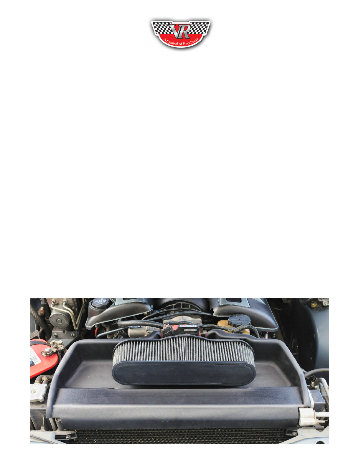
The All new Pontiac GTO/Holden, VR-SDR
(Vararam - Super Duty Racing Cold Air Induction System)
GTO/Holden (VR-SDR) Instructions
Tools needed
1. Flat head screwdriver or 8mm socket
2. Rotary saw with cutoff wheel (dremel)
3. Wire cutters
4. 30-45 min
Read the instructions completely through before beginning the installation, this includes the FAQ section.
We want your feed back, so drop us an email ([email protected]) or call us direct and let us know your
suggestions.
The GTO/Holden vehicle has a 3/4 inch variation from left to right and front to back and the engine is
twisted in the frame. We have made adjustments in the kit to allow for just about any combination. If you
run into something different during your install , don’t panic, our R&D department has over 20 different
combinations, just call us direct at 713-477-8100 and we will get you set up with what you need.
If you are uncomfortable with any aspect of this installation, simply allow a qualied installation technician to do the install for you.
Page 2
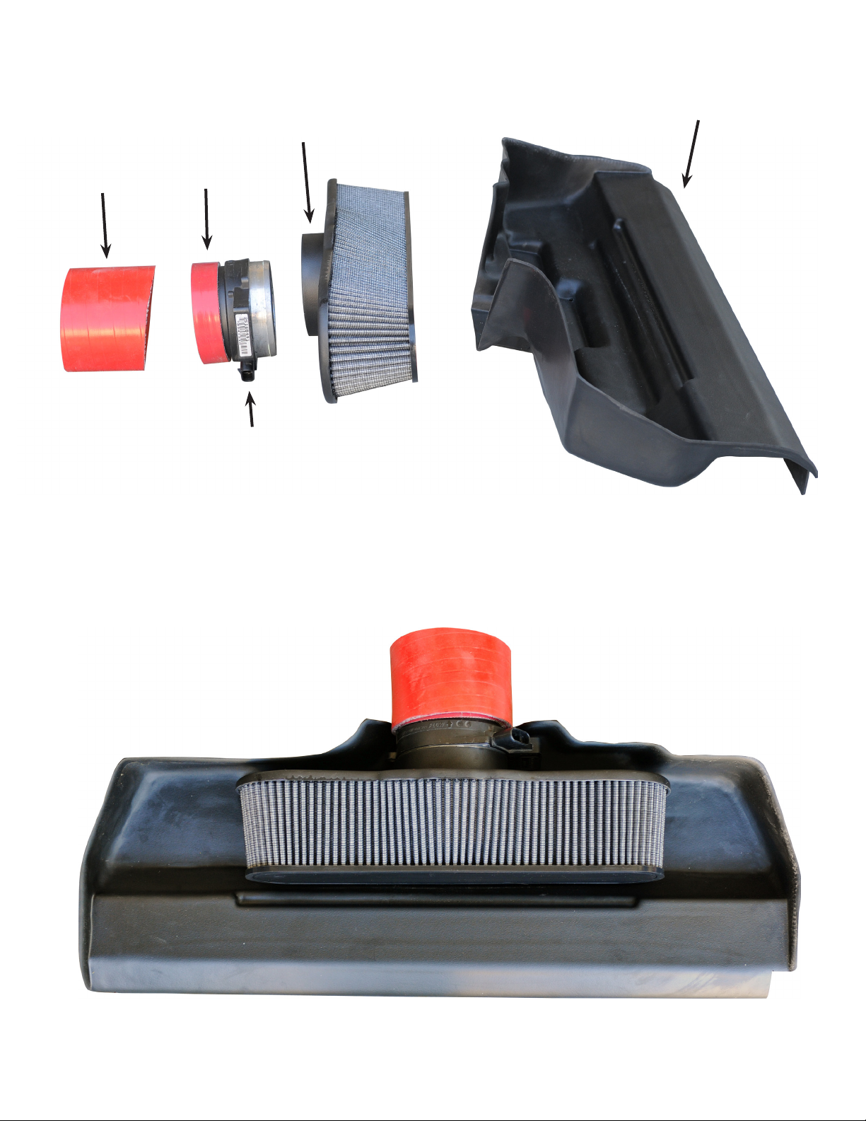
This is a blown up overview of how the kit ts together (side view)
lter housing
belly tray
angle hose
slip t hose
MAF
This is the kit assembled (top view)
Page 3
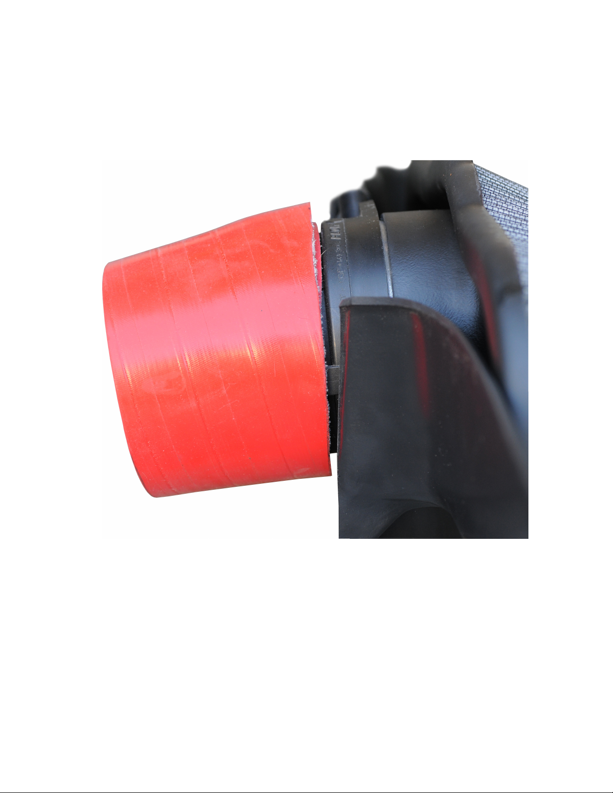
“Notice in the side view the angle cut hose”- this allows you to rotate the lter to the perfect horizontal
position, rather than pointing “UP” as your throttle body does.
Page 4
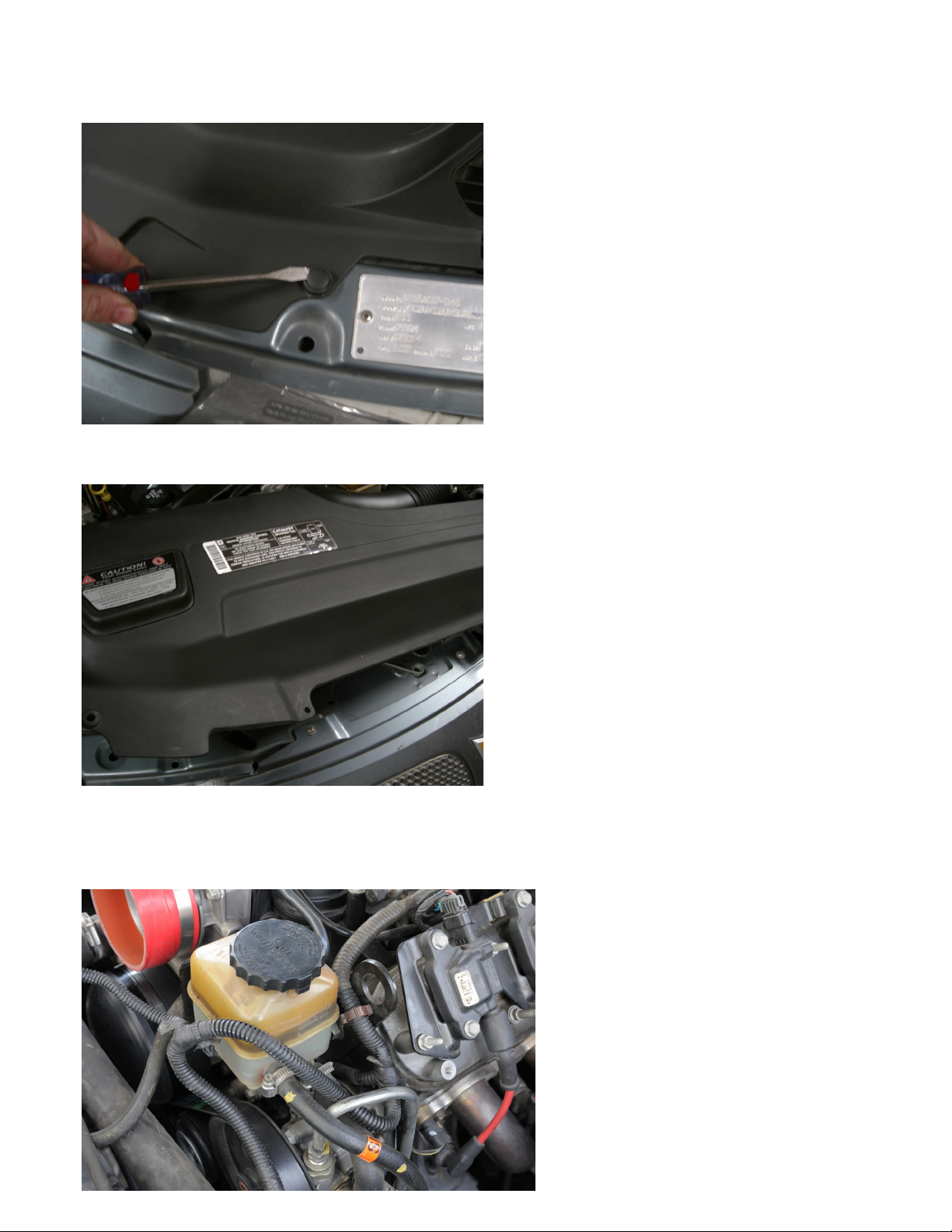
BEGINNING THE INSTALLATION
Remove your factory air box or existing cold air system.
Remove front facial cover by lifting the plastic push clips
Remove cover as shown
Pop or cut MAF wiring harness loose from driver side cylinder head, this is just behind and below the
power steering reservoir. This will give you extra slack allowing you to relocate the MAF in front of the
throttle body.
Page 5
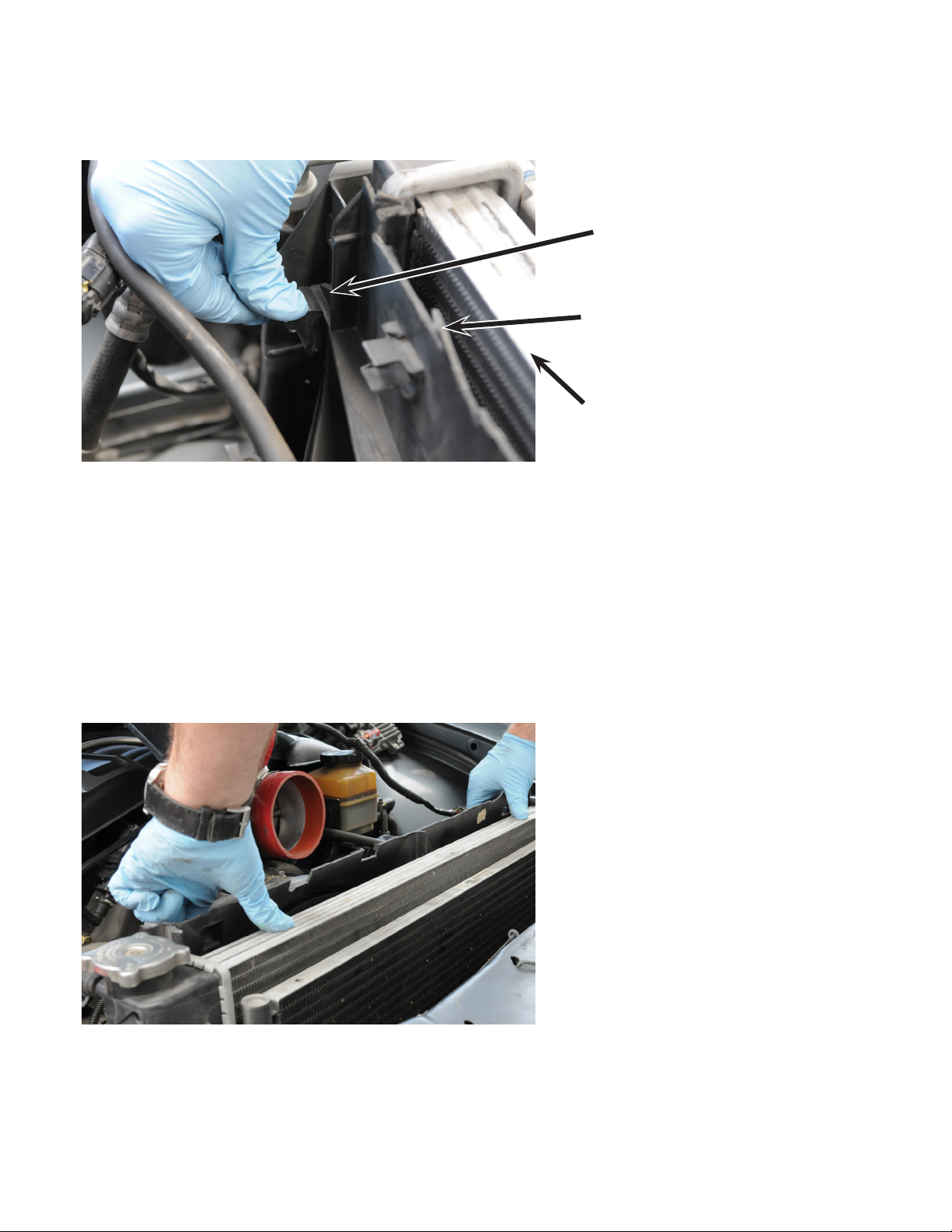
CUTTING THE SHROUD
Locate release clips approximately 1/4 the of the way down the “BACKSIDE” of the shroud (one on
each side)
Tab release
As shown after cut.
Top of radiator
Mark a “HORIZONTAL” line across the backside of the shroud 3/4 inch “BELOW” the top of the radiator line. This removes the small tabs that stick out at the back in one cut.
Next Release shroud from tabs and lift approximately 2-3 inches to allow for a safe cut. You can place a
piece of wood or something under the shrouds upper cover to hold it up and away from the radiator. We
used a short 2x4 but anything will do.
(You may want to place a towel in the engine compartment to keep it clean during the cutting process)
Using your cutoff wheel cut across the shroud. Once completed slide shroud back down into lock tabs,
your cut line should be 3/4 inches below the top of the radiator.
Page 6
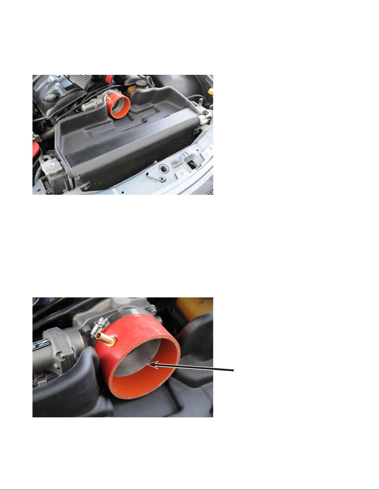
INSTALLING THE VR SYSTEM
(NOTE) there are many clearance cuts in the VR tray assembly, we have done this to allow for vehicle
variation and the many different applications from aftermarket intake manifolds to superchargers etc…
Start by placing the tray onto the radiator, notice the heat pad that is pre attached under the tray.
There are no brackets in this kit, the tray is a stressed member that is locked in place by the lter and
MAF connection and the hood when it is closed. (Refer to front overview picture if needed)
Using supplied hose (1) 3.5x1 inch for slip-t and (1) 4.0X2.5 inch angle cut hose with PCV already
tted. Slide the angle cut hose over mouth of throttle body, with the straight side towards the motor and
the PCV line pointing at the 11 o’clock position as shown. Tighten onto throttle body using supplied hose
clamp. (NOTE- check the transition inside from the hose ID to the ID of the throttlebody to ensure a
smooth transition, you may slide the hose clamp forward if needed about 1/4 inch or so to ensure a good
transition.)
(There were multitude of variations on the 6 GTO’s we used for R&D, this combination is used on a
stock vehicle with a stock intake manifold etc...)
Smooth transition
Page 7
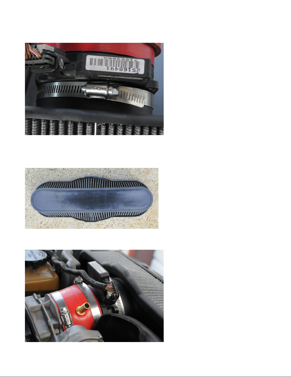
Counter sink MAF “INTO” the VR lter assembly , simply bottom this out, we precut this to set the desired depth. Use supplied hose clamp and tighten completely. Now place the (1) 1x3.5 hose “OVER” the
backside of the MAF. This is a slip t hose to bring the back of the MAF up to 4.0” O.D.
(NOTICE The lter is offset , this allows you to ip the lter by simply rotating it 180 deg. We do this
because your throttle body sits at an angle of 8-10deg pointing upward. This just allows you to further
compensate for vehicle variation to square everything up in the engine compartment. We like a clean factory racer look,so we have designed in lots of variation.
Fit lter housing with MAF into hose assembly as shown. You may need to use a athead screwdriver to
help you squeeze the hoses into place.
Rotate lter housing so that it sits horizontal not pointed up, this is why we have supplied you with the
angle cut hose that is on your throttlebody. (You can cut this hose further if needed)
Page 8

PCV
Using supplied PCV hose cut to length and simply press t hose into place.
FINAL PROCEDURE
Tighten all hose clamps, start vehicle and let idle with the hood closed until operating temp is reached
(210 deg F) for 5 min, now open hood and re-tighten MAF to VR airbox connection with a socket not a
screwdriver. This will cold form the plastic onto the MAF ensuring a precision t. (The plastics we use
are military spec and your lter housing uses a special mixture during the extrusion process . We mixed a
specied % of rubber compound with the ABS. This allows for -40 deg F and +275DegF without crack-
ing or stress) This is a VR Patented blend, that will never shatter or become brittle. Double check all connections especially the MAF wiring harness
Page 9

FAQ
Q: Do I need to custom tune the car after the lter installation?
A: ANY vehicle benets from a custom tune, but NO, you do not have to custom tune.
Q: My check engine light is on.
A: DO NOT PANIC, just allow the vehicle to learn the airow this takes about 100 miles of driving in
low and high RPM operation
Q: How often do I clean the lter?
A: The lter should be cleaned about every 8-10,000 miles.
General Tech Info #1-
This kit was built from day one to incase the airmeter inside the air box housing to help shield the
MAF from heatsoak. The system was built as a cold air, however, in testing it proved that through
data logging using HP tuners software that it would deliver colder than ambient temps. This is caused
by forcing air through the airmeter, which shows some ram effect. This has been reected in the units
high MPH improvements through the 1/4 mile, usually +3 mph on stock cars and +4 mph on modied
vehicles making 500 rearwheel HP+. Due to the GTO/ Holdens weight we concentrated the airboxes aero
package at shift recovery (4,500-5,500RPM) and in low end response to speed up engine windup, You
will nd that in real world testing there is “NO OTHER COLD AIR/ RAM AIR SYSTEM AVAILABLE
ANYWHERE” that can match the VR-SDR Systems on road/ track performance, NOBODY, NO
WHERE! Sorry AUSSIES your kits don’t even come close! We guarantee it or we will take the kit back!!
(check our webpage for more detailed R&D information, owbench testing etc.)
General Tech Info #2-
The GTO/ Holden system (VR-SDR) has gone through one of our most intense development programs.
the reason we took the time we did with this unit was because the car its used on has a massive amount of
variation, from motor alignment side to side front to back etc... If you look down the center of the car at
the motor it is actually twisted in the frame. There is simply no clear geometry , so we designed the kit to
move around side to side front to back with high mount throttlebodies as used on a blower combination
and stock mount as well.
If you run into something we have not compensated for, simply give us a call at 713-477-8100 chances
are our R&D dep has a solution, they built over 24 GTO prototypes and street/track tested them all with
different mounting combinations so chances are we have the x for your particular vehicle combination.
The lter - This may look small to some but make no mistake all VR lters are engineered to be as
compact as possible while maintaining minimal pressure drop across there surface area. We have spent
years designing street and race lters using all types of materials, foam,paper ,cotton gauze etc..Our
research has enabled us to establish formulas for every lter combination of pleat spacing and depth to
maximize both ow and ltration. The GTO Holden street units are rated up to a whopping 1500CFM!
(Race lters are available that can top 2000CFM)
We want feedback!! Call or email us: 713-477-8100 or [email protected]
 Loading...