

Page 1
ULS400
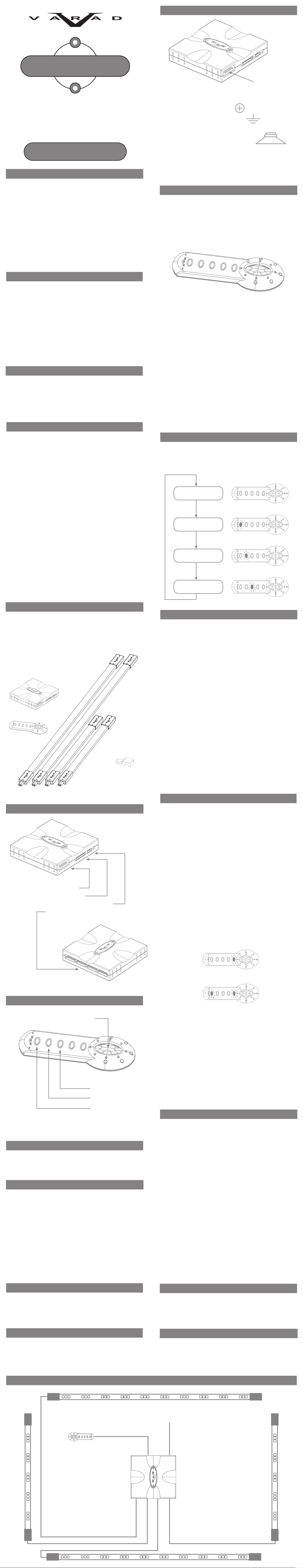
Wiring schematicWiring Schematic Continued
Connect wiring harness as indicated below:
SCANNING
LED UNDERCAR KIT
Installation Manual
General
Thank you for purchasing the ULS400 Scanning LED undercar
lighting system from VARAD. To ensure proper use, please read
this manual prior to installation.
The ULS400 demonstrates the innovation and technical abilities
of the engineering team atVARAD. Our latest kit combines superior
functionality with sleek product styling to put your ride at the
forefront of the tuner scene. With 4 low profile LED lightbars,
digital control module a nd a sleek wired hand-held controller,
you can command cool scanning patterns,strobing action or just
glow.With our patent pending new system configuration, optimum
color bleed is achieved using our latest high flux 70 degree LED’s.
These new high flux LED’s allow us to use fewer LED’s than those
found in typicalapplications to provide a more uniform and superior
color blend. If you demand the latest in lighting technology,
VARAD will take you there - Enjoy!.
• Red wire - Battery Positive
• Black wire - Negative (ground)
• Yellow wire - Ignition (+12v when ignition is “ON”)
• Blue wire - Positive speaker terminal
• White wire - Network (See “Networking pg 14”)
When all controllers and LED lightbars are installed you can
proceed to plug all connectors into the ULS400C controller.
Proceed to the “Operation of ULS400” section.
Operation of ULS400
The ULS400 is operated with a single button remote control. All
features can be controlled by three types of button operations:
• “Push and Hold” (greater than 1 second) to change modes.
• “Push and release” (momentary) to change features in
selected mode.
• “Double click” to change speeds (Mode 2 only)
Features
• 12 Scanning, 3 Strobing, 3 Comet and 2 Breathing patterns. 3
selectable speeds.
• S olid glow with 4 levels of intensity control.
• Selectable Music Reactor frequencies (40hz,80hz, 120hz).
• Network of multiple systems.
• Remote control acts as a SCANNERS™ Visual Theft Deterrent
when ignition is turned off.
• Compact digital controller for ease of installation.
• Wired remote control with LED’s that indicates pattern.
• Connectors on all LED lightbars for quick install.
• Low profile tub es (0.5”x 0.7”).
• Waterproof polycarbonate LED lightbars.
• Optional wireless remote control - ULS400WRC.
Precautions
To prevent fire or shock hazard,do not expose the digital controller
to rain or moisture.
To avoid electrical shock, do not open the digital controller. Refer
servicing to a factory authorized dealer.
Replace the fuse only with the type provided in the fuse holder.
Failure to do so c an cause malfunction.
Technical Specifications
For example:
To turn system “ON”
Push and hold button until Mode 1 LED is active. The system will
power up and go into Mode 1 (Solid Glow). The default intensity
is level 4 (Maximum brightness). Each momentary push of the
button will change the intensity level. Refer to “Mode Operation
Flow Chart” for more details.
There are three modes of operation:
Mode 1 - Solid Glow
Mode 2 - Scanning patterns/strobe/Breathing/Comet
Mode 3 - Music Reactor
Refer to “Mode Features” on page 13 for details on features for
each mode.
Turning system“OFF”
To turn the system“off”quickly, push and hold button until all
lights on the remote control turn “off”. This will take a few
seconds only.
Patterns:11 Scanning,3 Strobe, 2 breathing, 3 Comet
Speed: 3 selectable speeds
Glow: 4 Intensity levels
Music Reactor Frequencies: 40hz, 80hz, 120hz
Network ready for multiple kits
Physical Specifications:
Digital controller:
Height - 0.8”
Width - 4.0”
Length - 3.75”
Current draw - 20 ma to 1.4 amps depending on mode or pattern
Remote Control:
Height: 0.4”
Width: 1.25”
Length: 3.5”
LED LightBar:
Long LED LightBar length is 48.5” +/- 0.5”
Short LED LightBar length is 25” +/- 0.5”
Wires:
Each light bar has 12’ of cable
Electrical specifications:
LED’s:
Orange - ALINGAP,70ma, 70 degree
Red/Yellow - TS ALINGAP, 70ma, 70 degree
Blue/Green/White/Aqua - INGAN, 50ma, 70 degree
Mode Operation flow chart
“Push and Hold”
to change modes
Release button when mode
LED is illuminated
No Illuminated LED’s
OFF
LED 1 “ON”
MODE 1
GLOW
LED 2 “ON” momentarily
MODE 2
SCANNING
LED 3 “ON”
MODE 3
MUSIC REACTOR
Parts list
ULS400C - Digital controller.
1.
ULS400RC - Wired remote control.
2.
Two 48.5” LED lightbars.
3.
Two 25” LED lightbars.
4.
Power harness.
5.
Self tapping screws,12pcs.
6.
Tie straps,12pcs.
7.
Mounting clamps, 12pcs.
8.
Installation manual.
9.
ULS400C - Digital controller
ULS400RC -Remote control
Mode Features
Mode 1 • Solid Glow
Mode 1 features solid lighting of all segments.In this mode
you can select from four different levels of brightness.To
change the brightness level push the button once and
release.The remote control will show up to four LED’s
indicating the intensity level of the LED light bars. One LED’s
is for level 1,two LED’s is for level 2, three LED’s is for level 3
and four LED’s for maximum brightness.
Mode 2 • Scanning/Strobing/Breathing
When in mode 2 you can select the following with each
momentary push of the button. The system will remember
the pattern next time you return to this mode.
To change speed - Double click the button.There are 3
speeds available for most patterns.
• 11 Scanning patterns
• 3 Strobe patterns
• 2 Breathing patterns
• 3 Comet patterns
Mode 3 • Music Reactor
Mounting clamp
Items not showto scale
LED Lightbars
ULS400C Digital Controller Description
Power Harness
Wired Remote Control
Optional Wireless Remote Controller (ULX300WRC)
LED Lightbars
When in mode 3 you can select the following with each
momentary push of the button.
• 40hz (LED no.3 will flash 2 times to confirm)
• 80hz (LED no.3 will flash 3 times to confirm)
• 120hz (LED no.3 will flash 4 times to confirm)
2
Networking Multiple Kits
Each ULS400C controller features a built in “network ready” feature.
This feature allows multiple kits to be installed at the same time
on large vehicles such as SUV’s,Limousines, Semi’s,RV’s and Marine
applications. To activate this feature simply connect the white
wire of all digital controllers together during installation and set
up the master as shown below.
Installation notes!
Only one wired remote control needed. The digital controller
with the wired remote controller will be designated“Master”.
Only the “Master” unit requires hook up of the music input wire
(Blue wire).
All controllers must have ground wire, positive wire and ignition
wire connected at the same location.This will ensure best network
communication.
All controllers must have their own fuse. Do not use one fuse for
all systems!
ULS400RC Remote Control Description
Mode / Pattern select button
Setting up the “Master” controller.
Step 1:
Step 2:
Step 4:
All “Slave” systems on the network will replicate the “Master”
system in the following way:
Mode 1: Solid.
All networked controllers will change to the master system “ONLY”
after the intensity has been selected.
Turn ignition“OFF”
Push and hold button until LED no.1 is “ON”.
(release button after LED turns “ON”).
Push button once to turnLED no.4 “ON”.Step 3:
Network mode is now “Active”.
To exit set up mode - Push and hold button until
allLED’s turn “OFF”.
Mode 3 LED indicator
Mode 2 LED indicator
Mode 1 LED indicator
The remote control also indicates the scanning pattern with each
of the 5 LED’s.Each LED on the remote control corresponds to a
section of the LED lightbar.
ULS400RC - Visual Theft Deterrent
The remote control will flash a Scanning pattern when ignition is
turned off.The Scanning pattern cannot be changed.
Installation of LED lightbars
Visually inspect underneath your vehicle to determine a suitable
location for mounting each LED lightbar. Hold the LED lightbar
up in the prospective mounting location to verify that it will not
interfere with existing parts under the vehicle.For the 48.5”
lightbars it is important that the wire leads face the same
direction (front or rear) to ensure symmetry of the Scanning
patterns.When you have found a suitable location, begin to
install the mounting clamps. There are 4 clamps for each side
lightbar and 2 for each front and rear lightbar. Space each clamp
approximately 1 foot between each other. It is important to
install all mounting clamps in a straight line. It helps to use a
reference point on the chassis such as the pinch weld seam, etc.
Mark each drilling point and pre-drill each hole with a 1/8”drill
bit. Install all clamps facing the same direction. Now hold the
lightbar up and install a tie strap through the clamp at each
mounting point. Trim excess tie strap material. Repeat the
process for each lightbar.
Mode 2: Patterns/Strobing/Breathing/Comet
All networked controllers will have an initial delay in synchronizing
to the master controller.
Mode 3: Music Reactor.
All networked units will react in sync with the master controller.
Trouble Shooting
System does not turn “ON”
Check to see that the ribbon cable from the remote
controller is fully inserted into the contro ller.
Check “Ign ition Wire”, make sure it i s getting constant 12
volts positive when engine is “ON”.
Check fuse. If fuse looks bent or blown replace with a 5amp
fast acting glass fuse.
Make su re that ribbon cable from remote control is not
pinched or damaged.
LED l ightbar does not work.
Check to see that cable be tween LED lig htbar and controller
is not damaged.
Plug into another port to verify tha t it is the LED lightbar.
A Section of my LED lightbar is not working
Plug LED lightbar into another port to verify that it is the
LED lightbar.
Check to see that all the wires on the LED lightbar connector
are fully inserted into the heade r.
For technical support:
Check website www.varad.com
or email questions to: techsupport@varad.com
Warranty
Required tools
• Wire stripper
• Wire cutter
• Assorted drill bits
• Cordless drill
• Screwdriver
Installation of Controllers
Install the Digital Controller inside the vehicle. Find a location
that will allow all the wires to the LED lightbars to connect
without binding. The location should be 36” from where you
decide to install the wired remote control. The wired remote
control should be installed in a location within reach of the
driver.
Wiring Schematic
See “Wiring Schematic Continued Page 9”
Register your product
In order to provide you with prompt warranty service and technical
su ppor t pl ease regist er y our product on line at
www.varad.com/techsupport/register. Be sure to have your product
serial number ready.This can be found on the bottom of the digital
controller.
Send us your photos
We would love to have pictures of your install on our street gallery.
Go to www.varad.com/street-gallery.html for more information.
WWW.VARAD.COM
Front of vehicle
• There are no specific plug
locations for plugging in the LED
light bars.
 Loading...