

Varad SPIDER-VS260, EVO-VS360, AERO-VS460, RAPTOR-VS560 User Manual
®
Tri-Color Series
Thank you for purchasing our new generation
of SCANNERS . With our latest LED
technology, microcontroller and software
design we have added many new features
to provide you with the best visual theft
deterrence ever. This generation of
SCANNERS have 40 new and exciting
patterns along with three color LEDs,
adjustable speeds and programmable
features. You can select from a variety of
color changing, glowing and strobe patterns.
Each pattern is unique and will provide extra
excitement for visual theft deterrence!.
SCANNERS is a registered trademark of Varad USA
®
®
®
IM-VSX60V2
Features:
• 40 Selectable patterns
• Tri - Color SMT LED - Red/Blue/Purple
• Network multiple SCANNERS
®
• Three speed selections.
• Low power enable/disable mode.
• Temporary shut down.
• Temporary low power mode.
Mounting the SCANNERS :
®
Find suitable location for installation. Drill any holes if
necessary and clean surface with rubbing alcohol to
remove oils. Use the provided 3M™ double sided tape
and mount. Refer to following diagram for wiring
instructions.
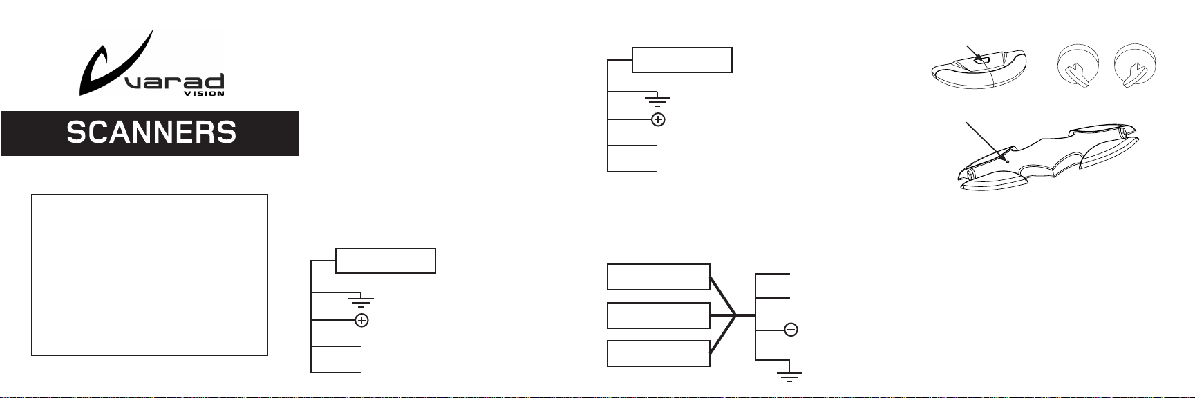
Installation with alarm system:
SCANNERS will activate when alarm system is activated.
Black
Red
Orange
White
®
SCANNERS
®
Battery negative or chassis ground
Battery positive (constant)
Alarm system accessory output or ground
output when armed.
Network for multiple SCANNERS . See
®
“Networking” for details
SCANNERS will activate when engine is turned off.
Black
Red
Orange
White
®
SCANNERS
®
Battery negative or chassis ground
Battery positive (constant)
Ignition - Ground when engine is “OFF”.
(See fuse box)
Network for multiple SCANNERS
®
installation. See “Networking” for details
Networking multiple SCANNERS :
This type of installation requires multiple SCANNERS .
®
®
Be sure to connect all wires together at the same location.
This will ensure proper network communication.
SCANNERS
SCANNERS
SCANNERS
®
®
®
White -
Orange
Red
Black
Connect all white
wires together.
How to operate SCANNERS :Installation without alarm system:
Program button
Program button on Raptor
(Use a small paper clip)
®
Ignition
OFF
Ignition
ON
How to select Patterns:
Ignition must be “ON”, press program button (Paper clip
for VS560C) momentarily and SCANNERS will display
®
next pattern. Repeat to view next pattern. The SCANNERS
has a total of 40 patterns. Note! - After 30 seconds you
cannot change patterns. To change patterns after 30
seconds cycle the ignition.
How to change speed:
Ignition must be “ON”, push program button rapidly two
times. SCANNERS will display the next speed. Repeat
to select next speed. The SCANNERS has three speed
®
®
selections.
®

Special Modes:
Occasionally, you may want to leave your vehicle for
extended periods of time. In order to save power and
maintain visual theft deterrence you can activate the low
power mode. Or, you can leave the SCANNERS off
®
completely. The following are instructions for each option.
How to select low power mode momentarily:
Ignition must be “ON”, hold program button until no.1 and
no.2 LED turn on then release (approximately 5 seconds
for no.1 LED and additional 5 seconds for no.2 LED).
SCANNER S will flas h tw o ti mes to confirm that
SCANNERS will be in low power mode when ignition is
®
®
turned off. This mode is temporary and will be reset when
ignition is turned on.
How to shut down momentarily:
Ignition must be “ON”, hold program button until no.1 LED
is on (all networked units) then release (approximately 5
seconds for no.1 LED to turn on). SCANNERS (all
networked units) will flash one time to confirm that
SCANNERS will remain off when ignition is turned off.
®
®
How to enable/disable low power mode:
If you’re not sure how long your car will be parked you
can program SCANNERS to enable/disable the low power
mode. When the low power mode is enabled, a clock
begins to count 5 days. After 5 days the SCANNERS will
®
®
activate the low power pattern with a single flashing LED.
The count down begins each time the ignition is turned
off. For network installations, only one unit needs to be
programmed. You do not need to program all units!
How to enable/disable low power mode (contd.)
Follow these steps:
Ignition must be “OFF”, hold program button until no.1
LED turns on (all networked units, approximately 7
seconds). Continue holding program button and turn
ignition “ON” then release program button. At this time
no.2 LED will turn on (all networked units). Now push
program select button one more time and the no. 3 LED
will turn on (all networked units). The SCANNERS is now
®
in the low power enable/disable mode. To enable the low
power mode push program select button and no.7 LED
will turn on (all networked units). This confirms that the
SCANNERS will activate the low power mode after
®
approximately 5 days. To disable the low power mode
push program select button and the no.7 LED will turn off
(all networked units). Turn ignition off to save and exit this
mode. The SCANNERS will flash once (all networked
®
units) each time the ignition is turned off to confirm that
the low power mode is enabled.
NOTE! Due to a wide variety of tolerances in electronic
components. The low power mode timing will vary between
2 to 8 days.
How to reset to default mode:
Under certain circumstances it may be necessary to reset
the SCANNERS (all networked units) to default mode.
Situations that will require a reset are when networked
SCANNERS are out of sync or you simply want to return
to the default mode. The following steps will allow you to
reset the SCANNERS :
®
®
®
How to reset to default mode (contd.)
Follow these steps:
Ignition “OFF”, hold program button until no.1 LED turns
on (all networked units, approximately 7 seconds). Continue
holding program button and turn ignition “ON” then release
program button. At this time no.2 LED will turn on (all
networked units). Now, turn off ignition and SCANNERS
(all networked units) will flash red then blue once to confirm
reset.
30 Second lock out:
The SCANNER patterns can only be changed for 30
®
seconds after ignition is turned on.
Trouble shooting - frequently asked questions
SCANNERS does not remember pattern
®
Memory loss will occur whenever the positive wire loses
contact with the battery for a moment. This can occur if
the positive wire is attached to the wrong contact on the
fuse box or some other location in the vehicle. Try to
connect the SCANNERS positive wire directly to the
®
battery positive terminal.
SCANNERS does not work when connected to my
alarm
If you want the SCANNERS to turn on when you activate
®
®
you alarm system you must connect the orange SCANNER
wire to the grounded output (when armed) of your alarm
system. DO NOT CONNECT TO THE LED OUTPUT!.
The LED output wire only provides a 2-3 volts flashing.
Refer to your alarm system installation manual or ask
your local dealer for the correct ground output wire.
My SCANNERS patterns are out of sync.
®
This can happen for many reasons. If you push the
program select button too fast or too soon before a pattern
cycle is finished. If there is a poor or loose connection on
the network wire line (white wire). If you push buttons on
more than one unit at a time. If this occurs you can perform
®
a “reset”. Refer to the “How to reset to default mode”
section.
My SCANNERS does not turn off when I arm my
®
alarm system.
This situation is caused by ground leakage through the
ignition kill relay. You must install a diode per the following
diagram.
®
SCANNERS
Alarm system
Varad’s product warranty covers against breakage due to defects in materials or workmanship
for one year from the date of purchase. Warranty is only valid with proof of purchase from
an Authorized Varad Dealer. Varad’s warranty program does not cover cosmetic damage,
and damage due to acts o f God, acci dent, misuse, abuse or negligence to the product.
Repair or replacement as provided under this warran ty is the exclusive remedy of the
consumer. Varad shall not be liable for any incidental or consequential damage for breach
®
of any express or implie d warranty on this product. Except to the extent provided by this
warranty or prohibited by applicable law, there are no implied nor expressed warranties or
merchantability or fitness for a particular purpose of this product.
Ground output
when armed
Red
Orange
Switching diode
1N4148, 1/2 Watt
www.varad.com
tech supp ort@ varad.com
Desig ned a nd E ngineere d in U.S .A. • Asse mbled in China
Black
Starter Kill
Relay
 Loading...