

Page 1
Page 2

Table of Contents
Intended Use................................................................................................................................................................. 3
Indications, Warnings and Cautions .......................................................................................................................... 5
Transfer Unit Components ................................................................ .......................................................................... 5
Transfer Unit Assembly ............................................................................................................................................... 6
Using the System ....................................................................................................................................................... 19
Cleaning and Maintenance ........................................................................................................................................ 21
Troubleshooting and Support ................................................................................................................................... 21
Referenced Documents ............................................................................................................................................. 21
Specifications ............................................................................................................................................................. 21
2 3100563 Rev. B
Page 3

Intended Use
The Vapotherm Transfer Unit (VTU) allows the mobile delivery of high-flow humidified respiratory therapy within a
hospital environment. With a fully charged battery module and full gas cylinders, the length of available mobile
therapy depends on 2 factors:
Cylinder gas supply: From 14 minutes to 18.7 hours, based on the O2/air gas ratio and flow rate settings
on the Precision Flow.
Battery life: Up to 1.5 hours from a full charge.
o Tripp Lite recommends that the Power Supply be plugged into a wall outlet, charging the battery as
often as possible. Charging the batteries for brief intervals DOES NOT adversely affect battery
performance. However, leaving the batteries fully discharged for long periods of time DOES
adversely affect battery performance.
o For long term storage, the battery should be fully charged at a minimum of once per month.
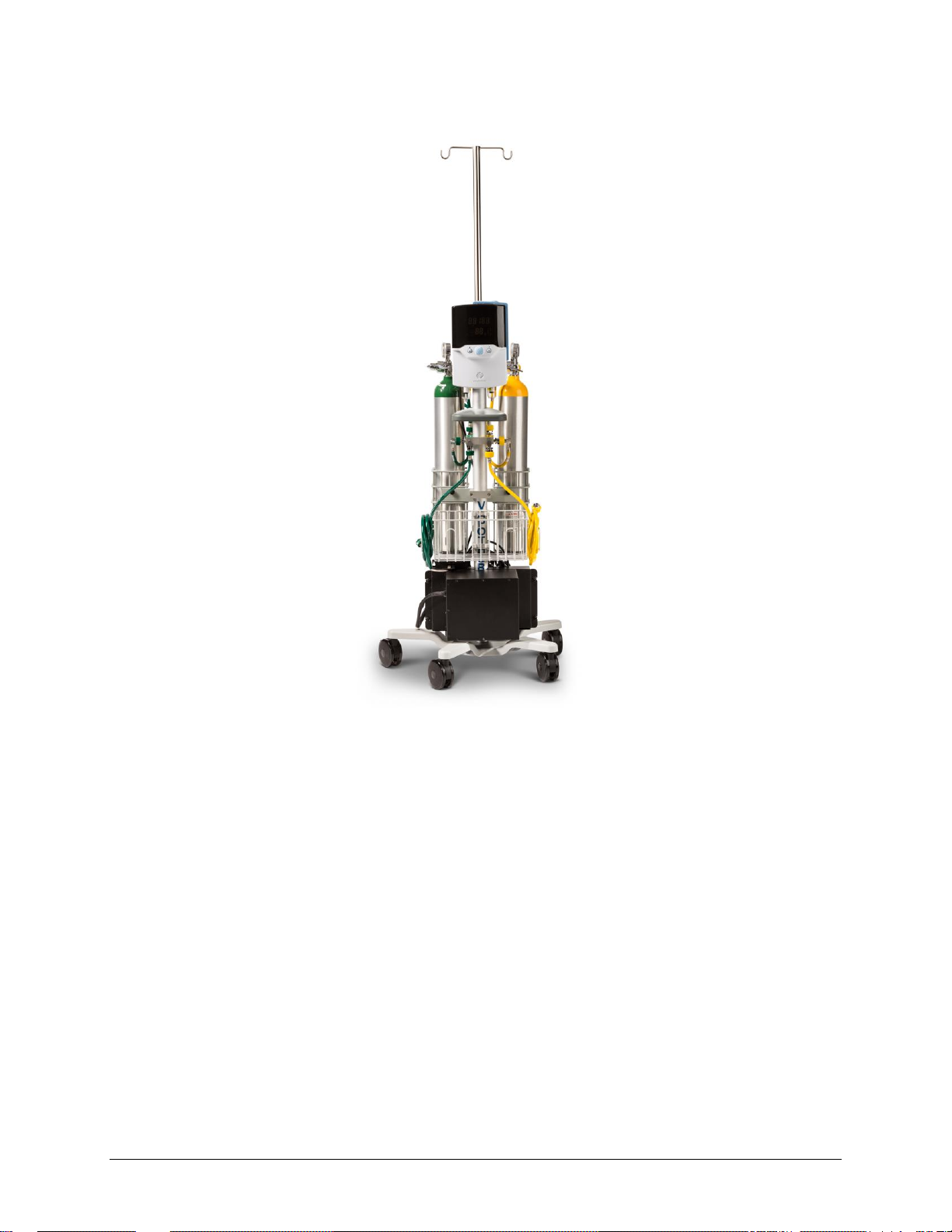
The VTU consists of the
GCX Roll Stand
Medical-Grade Mobile Power Kit
Medical Air and Oxygen Manifold and E-Cylinder Holder
Vapotherm Precision Flow (Optional)
3100563 Rev. B 3
Page 4
4 3100563 Rev. B
Page 5

Indications, Warnings and Cautions
Item Description
Qty
Precision Flow Roll Stand – 5 Wheel Locking Base
1
Mounted Medical-Grade Mobile Power Supply Kit:
Battery Module
Power Supply Module
Remote User Interface
Communication Cables (1 Black – 1 Grey)
1
1
1
1
Manifold and E-Cylinder Holder Kit:
Air Manifold Block with CGA 950 Regulator,
preset at 50 PSI, and Air Hosing
Oxygen Manifold Block with Hosing
Dual E-Cylinder Holder
AC Plug Cover
NOTE: The VTU does not ship with an oxygen regulator.
1
1
1
2
Tools Required:
5/32” (4 mm) Hex Wrench
Phillips Screwdriver (for 10-32 x 9/16” PHMS)
1
1
For ease of assembly and to avoid injury when handling the heavy power components, the VTU should be assembled
by a minimum of 2 trained professionals.
Only the Tripp-Lite Medical-Grade Mobile Power Retrofit Kit, model HCRK-36, has been validated for use with the
Vapotherm Precision Flow. Using a power supply not validated by Vapotherm for use with the Precision Flow may
result in inadequate device performance. Battery should be fully charged once a month at a minimum.
Before assembly and use of the system, please refer to the following indications, warnings and cautions:
Vapotherm Precision Flow: Indications, Warnings and Cautions, as published in the Precision Flow Operating
Instruction Manual.
Tripp Lite Medical-Grade Mobile Power Retrofit Kit: Important Safety Instructions, as published in the
Owner’s Manual.
To understand the alarm behavior of the system, please refer to the description of alarms in the following
documentation:
Vapotherm Precision Flow Operating Instruction Manual
Tripp Lite Medical-Grade Mobile Power Retrofit Kit Owner’s Manual
The VTU shall only be used in medical settings including the following medical environments: NICU, PICU, Adult
ICU, Medical ICU, Cardiothoracic ICU, Surgical ICU, PACU, Long Term Acute Care Hospital, and Emergency
Departments.
The VTU is not MRI compatible.
The VTU should never be used in pre-hospital settings.
Transfer Unit Components
Before assembling the Vapotherm Transfer Unit, make sure that you have the following system components:
3100563 Rev. B 5
Page 6
Vapotherm Transfer Unit Assembly
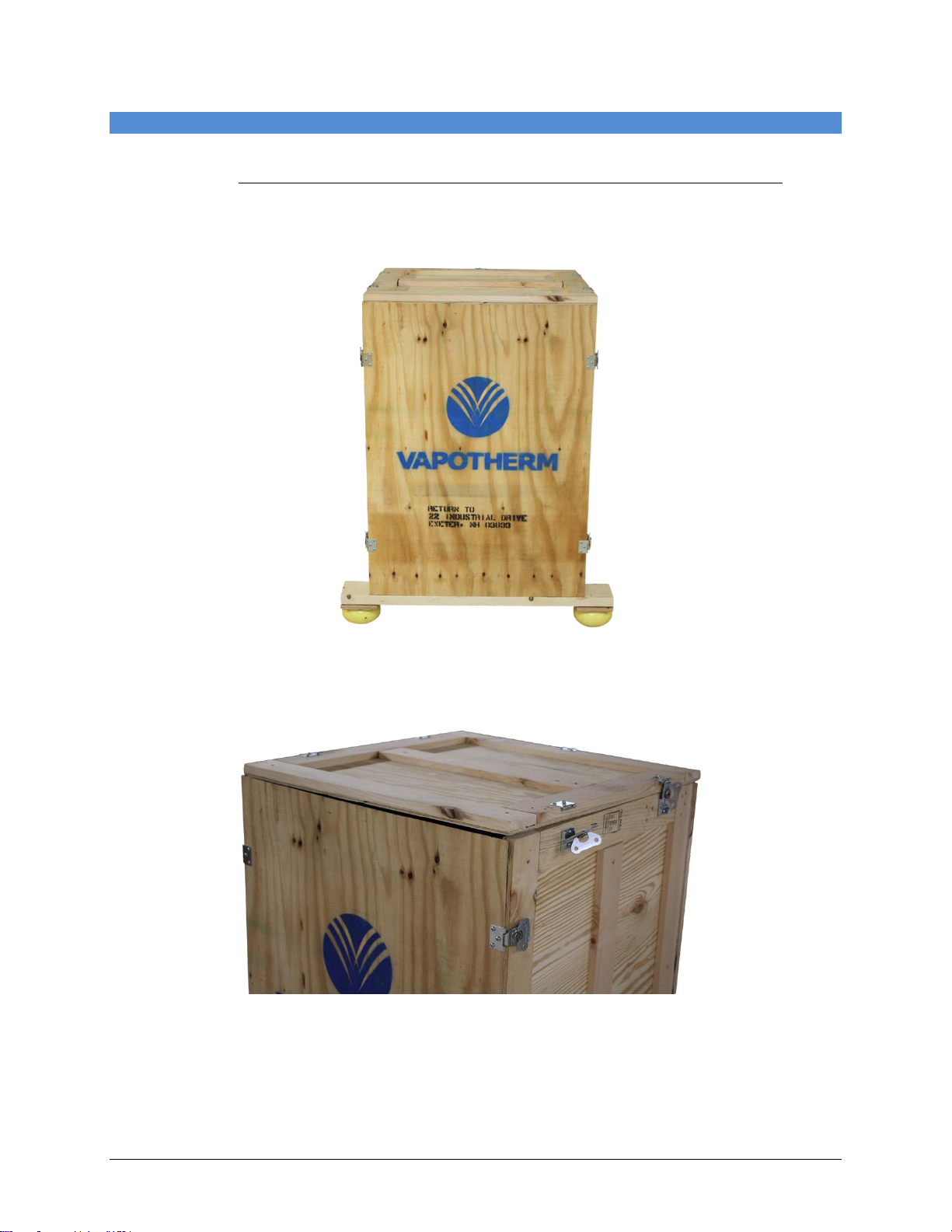
For ease of assembly, Vapotherm recommends the following assembly sequence. The VTU arrives in the Vapotherm
Transfer Unit Crate. The VTU Crate is reusable and should be sent back to Vapotherm after VTU assembly.
Vapotherm Shipping Address: 22 Industrial Drive, Exeter, New Hampshire, 03833
1. The VTU arrives in the crate shown below.
2. Remove the lid of the crate by unlatching the fasteners (5).
6 3100563 Rev. B
Page 7
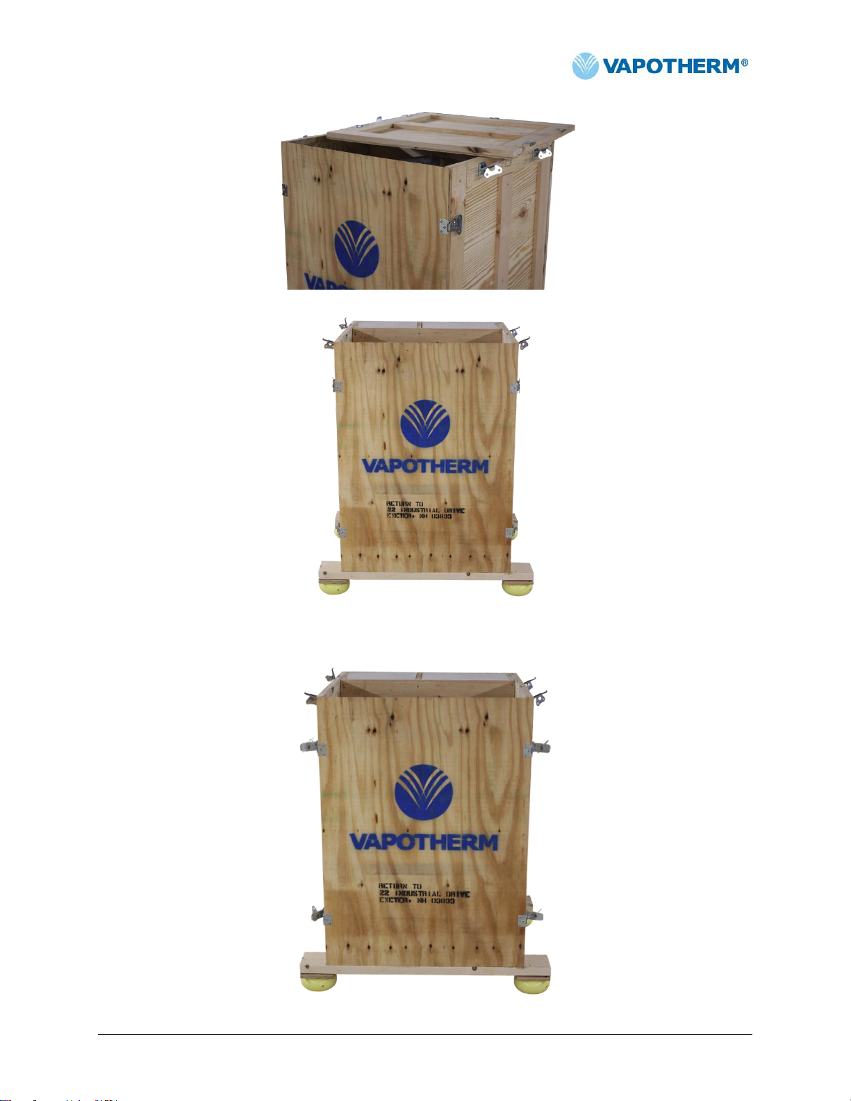
3. Unlatch the fasteners (4) on the front of the crate.
3100563 Rev. B 7
Page 8
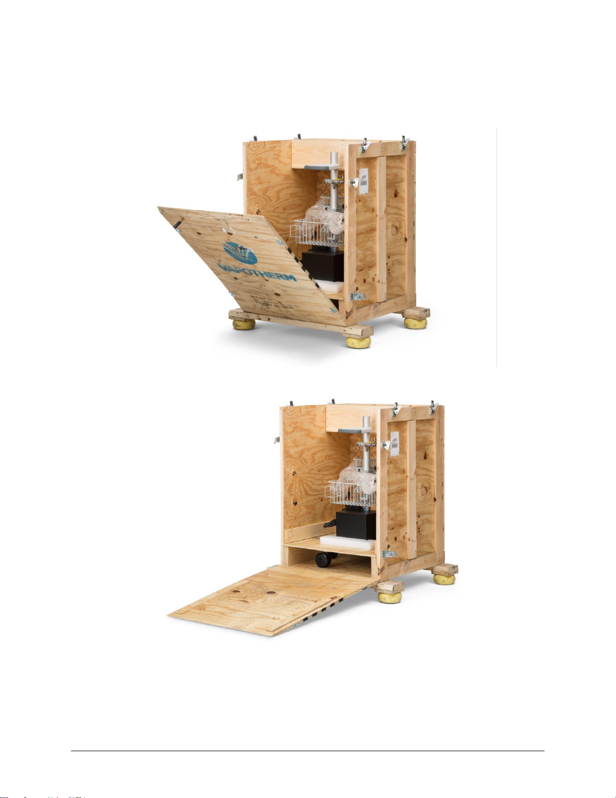
4. Open the front panel door to reveal the VTU components.
8 3100563 Rev. B
Page 9

5. Confirm that the crate door is resting on the base edge.
6. Remove the board that is securing the VTU in the crate.
3100563 Rev. B 9
Page 10

7. Unlock the VTU wheels and roll the VTU out of the crate.
8. Cut the cable tie and remove the top portion of the PF roll stand from the packaging.
9. Remove the 5/32” (4 mm) hex screws from the top of the PF roll stand.
10 3100563 Rev. B
Page 11

10. Attach the top of the PF roll stand by aligning the screw holes and insert the 5/32” (4 mm) hex screws.
11. At this point the VTU should match the image below.
3100563 Rev. B 11
Page 12

12. Locate the VTU accessory compartments in the VTU crate.
13. Remove the air and oxygen hoses from the VTU crate compartment.
14. Remove the hoses from the packaging. For both air and oxygen there are two 3-foot hoses and one 10-foot
hose. Attach the 10-foot air hose labeled WALL to the corresponding connection port on the air manifold also
labeled WALL. Coil the air hose around the Precision Flow roll stand basket.
15. Attach the 10-foot oxygen hose labeled WALL to the corresponding connection port on the oxygen manifold also
labeled WALL. Coil the oxygen hose around the Precision Flow roll stand basket.
12 3100563 Rev. B
Page 13

16. Attach the 3-foot air hose labeled VT UNIT to the corresponding connection port on the air manifold also labeled
VT UNIT.
17. Attach the 3-foot oxygen hose labeled VT UNIT to the corresponding connection port on the oxygen manifold
also labeled VT UNIT.
3100563 Rev. B 13
Page 14

18. Attach the 3-foot air hose labeled TANK to the corresponding connection port on the air manifold also labeled
TANK.
19. Attach the 3-foot oxygen hose labeled TANK to the corresponding connection port on the oxygen manifold also
labeled TANK.
20. At this point the VTU should resemble the image below.
21. Remove the items below from the VTU accessories compartment to finish assembly of the mobile power supply
(Grey Communication Cable, Black Communication Cable, Cable Tie Kit, and Battery Functional Test Report).
14 3100563 Rev. B
Page 15

22. Remove the protective bubble packaging from the power cord with the yellow receptacle and insert it into the
inverter.
23. Remove the black communication cable from the package and insert it into the inverter. The cable should be
inserted into the receptacle labeled COMM2 BLACK.
3100563 Rev. B 15
Page 16

24. Remove the grey communication cable from the package and insert it into the inverter. The cable should be
inserted into the receptacle labeled COMM1 GREY.
25. Insert the other end of the black communication cable into the Remote User Interface COMM2 receptacle. Insert
the other end of the grey communication cable into the Remote User Interface COMM1 receptacle.
26. Use a cable tie to secure the black and gray cables.
16 3100563 Rev. B
Page 17

27. Install the Precision Flow Unit on the PF roll stand.
PF base approx. ≤ 40” above
floor
3100563 Rev. B 17
Page 18

28. Attach the hoses labeled VT UNIT for the air and oxygen to the Air and O2 traps at the back of the Precision Flow
device. Attach the air and oxygen hoses labeled TANK to their corresponding 50 psi regulated E-cylinder.
29. The VTU should resemble the image below.
30. The VTU crate ships with the following documents: PF VTU Crate IFU, VTU Quick Reference Guide, and Mobile
Power Supply Operators Manual. The VTU crate is reusable and needs to be returned to Vapotherm.
a. Place the return-shipping label on the top panel of the VTU crate and insert the RMA in the folder inside
the VTU crate. (Customers will be charged for crates that are not returned)
b. Vapotherm Shipping address: 22 Industrial Drive, Exeter New Hampshire, 03833
18 3100563 Rev. B
Page 19

Using the System
Preparation
To run the Precision Flow with wall gas across its full operational range, attach the 10-foot oxygen and air
hoses to a minimum of 40-psi gas supply.
Before switching from wall to tank gas, make sure that the E-cylinders contain adequate gas supplies (2000
psi).
Allow the power supply to charge for 24 hours prior to initial use. The power supply should be fully charged
before using the VTU for mobile therapy delivery.
Before disconnecting the VTU from line power, make sure that the power supply is turned on. This is
indicated by 5 LEDs on the power supply Remote User Interface.
Transfer Setup
1. Connect the yellow VT UNIT 3-foot air hose to the air trap (AIR), and the green VT UNIT 3-foot oxygen hose
to the oxygen (O2) trap on the Precision Flow.
2. Plug the Precision Flow into the medical grade mobile power supply.
3. Insert the oxygen E cylinder into the dual cylinder holder.
Repeat for the compressed air E Cylinder.
Note: Insert the oxygen E Cylinder on the same side as the oxygen trap on the Precision Flow.
4. Install the air and oxygen E Cylinders:
Connect the oxygen TANK 3-foot oxygen hose to the oxygen E cylinder.
Connect the air TANK 3-foot air hose to the air E cylinder.
5. Power on the medical grade mobile power supply.
Switching Gas and Power Sources
1. Confirm the Precision Flow therapy settings.
2. Open the oxygen and air E cylinders and confirm that the cylinders contain adequate gas supply.
Warning: Do not attempt to transfer a patient with ≤ 400 psi in either tank.
3. Disconnect the oxygen and air hoses from the wall gas supply.
4. Unplug the power cord from the medical grade mobile power supply and store securely on the unit.
Warning: Make sure the power cord does not drag on the floor and present a tripping hazard. Place the
power cord into the VTU roll stand basket.
5. Transfer patient to desired location within the hospital.
3100563 Rev. B 19
Page 20

6. At destination
Connect the oxygen and air hoses to the wall gas supply,
Plug the medical grade mobile power supply into a hospital-grade outlet.
Close the E cylinders once connected to a wall gas supply.
Note: When the VTU is stationary, lock the wheels of the PF Roll Stand.
Warning: If the Precision Flow continuously sounds a gas alarm, confirm that all connections to the gas supply (wall
or tank) are correct or that there is adequate gas supply in the tanks. Refer to the Precision Flow Operating
Instruction Manual for detailed information about the Precision Flow’s alarm behavior.
20 3100563 Rev. B
Page 21

Cleaning and Maintenance
Flow:
1-40 L/min
Temperature:
33-43C
Oxygen Delivery:
21-100%
Ambient Temperature:
18-30C
Relative Humidity:
20-90% non-condensing
Ambient Pressure:
Standard atmospheric – not to be used in hyperbaric conditions
Ambient Temperature:
10-50C
Relative Humidity:
20-90%
ISO 8185:2007(E); Requirements for Medical Humidifiers
ISO 14971 Risk Management
IEC 60601-1 3rd Edition
ISTA-2A, Ship Test
ASTM G93/CGA G-4.1 Off-the-Shelf components coming into contact with gas supply
For cleaning and maintenance instructions for the Precision Flow, please see the Precision Flow Operating
Instruction Manual.
For maintenance and storage instructions for the medical grade mobile power supply, please see the Tripp Lite
Medical-Grade Mobile Power Retrofit Kit Owner’s Manual.
For cleaning and maintenance instructions for the PF Roll Stand, please see the PF Roll Stand Installation Guide.
Troubleshooting and Support
If you need assistance with the Vapotherm Precision Flow, please contact your local Clinical Product Specialist or
email Vapotherm Technical Support at TS@vtherm.com (855-557-8276)
Referenced Documents
Vapotherm Precision Flow Operating Instructions Manual
Document Number: 3001002
GCX Roll Stand Kit Installation Guide
Document Number: DU-VAP-0001-61
Tripp Lite Owner’s Manual for Medical-Grade Mobile Power Retrofit Kit
Document Number: 200910241 93-2704-EN
Specifications
Precision Flow Operation and Performance
Environmental Criteria
Storage and Shipping
Standards
Designed to conform to the following standards:
3100563 Rev. B 21
Page 22

VTU Mobile Therapy Delivery Times
Total
Flow
% Oxygen
L/min
21%
30%
35%
50%
60%
70%
80%
90%
100%
1
560
632
681
681
1106
903
750
641
560
2
280
316
340
340
553
451
375
321
280
3
187
211
227
227
369
301
250
214
187 4 140
158
170
170
277
226
187
160
140 5 112
126
136
136
221
181
150
128
112
6
93
105
113
113
184
150
125
107
93
7
80
90
97
97
158
129
107
92
80
8
70
79
85
85
138
113
94
80
70
Total
Flow
% Oxygen
L/min
21%
30%
35%
50%
60%
70%
80%
90%
100%
5
112
126
136
136
221
181
150
128
112
6
93
105
113
113
184
150
125
107
93
7
80
90
97
97
158
129
107
92
80
8
70
79
85
85
138
113
94
80
70
9
62
70
76
76
123
100
83
71
62
10
56
63
68
68
111
90
75
64
56
15
37
42
45
45
74
60
50
43
37
20
28
32
34
34
55
45
37
32
28
25
22
25
27
27
44
36
30
26
22
30
19
21
23
23
37
30
25
21
19
40
14
16
17
17
28
23
19
16
14
Low Flow Use Table (Duration of use blending from E-size oxygen and E-size air cylinders; times shown in
minutes).
High Flow Use Table (Duration of use blending from E-size oxygen and E-size air cylinders; times shown in minutes)
Warning: These mobile run time estimates are based on use of a 2000-psi E cylinder. Actual performance may vary
depending on the amount of gas in the cylinders.
The Vapotherm Transfer Unit (VTU) allows the mobile delivery of high-flow humidified respiratory therapy within a
hospital environment. With a fully charged battery module and full gas cylinders, the length of available mobile
therapy depends on 2 factors:
Cylinder gas supply: From 14 minutes to 18.7 hours, based on the O2/air gas ratio and flow rate settings
on the Precision Flow.
Battery life: Up to 1.5 hours from a full charge.
22 3100563 Rev. B
Page 23

Page 24

Warranty
Vapotherm expressly warrants, for a period of ninety (90) days from the date of shipment by Vapotherm to the initial purchaser of
the Vapotherm Transfer Unit (“Customer”) that the Vapotherm Transfer Unit device shall meet the specifications set forth in the
applicable official operating instructions for use provided with each Vapotherm Transfer Unit (the “Instructions”). The sole remedy for
this warranty is that Vapotherm shall, at its sole option, either refund, repair or replace any part or all of any Vapotherm Transfer Unit
that is defective at no cost to the Customer. Vapotherm shall pay any shipping charges required in repairing or replacing any part or
all of a Vapotherm Transfer Unit during the warranty period. Customer shall be responsible for the cost of labor for repairs. This
warranty does not apply to any other Vapotherm Product, including without limitation the Precision Flow device, the disposable
patient circuits and hoses used with the Precision Flow device, or any disposable component used with the Precision Flow device.
The warranty set forth herein shall become null and void if: (1) the Vapotherm Transfer Unit is not used or serviced in accordance
with the applicable Instructions or any related preventative maintenance instructions provided with the Vapotherm Transfer Unit; or
(2) the Vapotherm Transfer Unit is tampered with, or if repairs or service are performed or attempted on the Vapotherm Transfer
Unit by anyone other than Vapotherm or a Vapotherm-certified service center.
EXCEPT AS EXPRESSLY SET FORTH ABOVE, VAPOTHERM MAKES NO WARRANTY, EXPRESS, IMPLIED, STATUTORY OR
OTHERWISE, WITH RESPECT TO THE PRODUCTS OR ANY OTHER ITEMS PROVIDED BY VAPOTHERM, AND HEREBY
EXPRESSLY DISCLAIMS ANY OTHER FORM OF WARRANTY, INCLUDING, WITHOUT LIMITATION, ANY WARRANTY OF
MERCHANTABILITY OR FITNESS FOR A PARTICULAR PURPOSE. THIS STATED WARRANTY IS EXCLUSIVE AND IN LIEU
OF ALL OTHER WARRANTIES PROVIDED BY LAW.
Vapotherm Inc.
22 Industrial Drive
Exeter, NH 03833
USA
Phone: 603-658-0011
Fax: 603-658-0181
3100563 Rev. B
 Loading...