

Page 1
Precision Flow® Hi-VNI
Instructions for Use
Page 2

Table of Contents
Symbols 3
Section 1 Indications, Warnings and Cautions 4
Section 2 Overview 7
Section 3 Principles of operation 8
Section 4 Controls, displays & connections 10
Section 5 Modes of operation 13
Section 6 Initial assembly 14
Section 7 Setting up 15
Section 8 Adjustments 19
Section 9 Connecting to patient 20
Section 10 Operating guidelines 21
Section 11 Changing the disposable patient circuit 22
Section 12 Alarms 23
Section 13 Shut down 27
Section 14 Routine maintenance 27
Section 15 Cleaning and disinfection 28
Section 16 Specifications 29
Appendix:
Audio Tone Characteristics 32
Software modes 33
EMC Guidance 34
Page
Precision Flow® Hi-VNI Packaging contains:
Precision Flow® Hi-VNI Unit
Instructions for Use (USB)
Quick Reference Guide
Power Cord
O2 Sensor Cell
Air & Oxygen Inlet Particulate Traps with Connectors
US ONLY- Air and Oxygen Hoses
Nurse Call / EMR Communication Cable
with adapter cables (varies by country)
Quick Set Up Sticker (English speaking countries only)
Delivery Tube clip
Page 2 Precision Flow Hi-VNI Instructions for Use 3101477-01-EN Rev B
Page 3
MR Unsafe
Vapotherm Inc. has declared that this product conforms with the European
Council Directive 93/42/EEC Medical Device Directive when it is used in
accordance with the instructions provided in the Instructions For Use.
This symbol indicates that the waste of electrical and electronic equipment
must not be disposed as an unsorted municipal waste and must be collected
separately. Please contact an authorized representative of the manufacturer for
information concerning the decommissioning of your equipment.
Precision Flow Hi-VNI Instructions for Use 3101477-01-EN Rev B Page 3
Page 4

Section 1 Indications, Warnings and Cautions
General Indications & Contraindications.
Primary Indications:
Precision Flow® Hi-VNI is intended for use to add warm moisture to breathing gases from an
external source for administration to a neonate/infant, pediatric and adult patients in the hospital
and subacute institutions settings. It adds heat and moisture to a blended medical air/ oxygen
mixture and assures the integrity of the precise air/oxygen mixture via an integral oxygen
analyzer. The flow rates may be from 1 to 40 liters per minute via nasal cannula.
Precision Flow® Hi-VNI provides high velocity nasal insufflation (HVNI) with simultaneous
oxygen delivery to augment breathing of spontaneously breathing patients suffering from
respiratory distress and/or hypoxemia in the hospital setting. Precision Flow® Hi-VNI is not
intended to provide total ventilatory requirements of the patient and not for use during field
transport.
Contraindications:
General:
• Not appropriate for patients who are not spontaneously breathing, are unable to protect
their airway or have anatomic or injury induced blockage of the nasal pathway to the
nasopharyngeal space
• Not for treating OSA and snoring
• The Precision Flow® Hi-VNI is not for field transport
• The Precision Flow® Hi-VNI is MRI unsafe. Do not use it in an MR environment.
Warnings and Cautions
A Warning indicates that a situation may occur which is potentially harmful to the patient or user.
A Caution indicates a condition that may lead to equipment damage, malfunction, or inaccurate
operation. A Note indicates a point of emphasis to make operation more efficient or convenient.
Please take the time to familiarize yourself with the warnings, cautions, and notes listed in
these instructions. They cover safety considerations, special requirements, and regulations.
The user of this product shall have sole responsibility for any malfunction due to operation
or maintenance performed by anyone not trained by Vapotherm staff or official training
documentation.
When handling any part of the Precision Flow® Hi-VNI, always follow hospital infection
control guidelines and Standard Precautions. Vapotherm also recommends that users follow
the Centers for Disease Control (CDC) publications: Guidelines for Maintenance of In-Use
Respiratory Therapy Equipment and Guidelines for Prevention of Nosocomial Pneumonia.
General Warnings
Federal Law (U.S.) restricts the sale of this device to, or by the order of any physician. This
device should be used ONLY by a trained respiratory therapist or certified operator. Training is
to be provided and shall be conducted by authorized Vapotherm personnel only.
This is a humidification device generally used for providing continuous flows of breathing gas.
The Precision Flow® Hi-VNI is not a ventilator and should not be used as life support.
Oxygen supports combustion; this device should not be used near or around open flames, oil, or
grease, or flammables.
Service on the device should only be performed by qualified, certified service technicians.
To prevent injury, do not attempt to do any service to the Precision Flow® Hi-VNI while a patient
Page 4 Precision Flow Hi-VNI Instructions for Use 3101477-01-EN Rev B
Page 5

Section 1 Indications, Warnings and Cautions
is connected to the device.
If the device is damaged or not working properly, do not use. Contact Vapotherm or your
authorized Vapotherm representative.
Do not operate if power cord is damaged.
No modification of the equipment is allowed. Do not modify this equipment without
authorization of Vapotherm. If this equipment is modified, appropriate inspection and testing
must be conducted to ensure continued safe use of the equipment.
The device should not be placed in run mode and left unattended in a non-care environment.
When utilized in a care environment, operator shall remain close enough to hear the alarms.
Do not use the Precision Flow® Hi-VNI at an altitude above 6,392 feet or outside a temperature
of 18-30°C. Using the Precision Flow® Hi-VNI outside of this temperature range or above this
altitude can affect the quality of the therapy or injure the patient.
Do not use the Precision Flow® Hi-VNI in or around water, other than the sterile water supply
that feeds the system.
Do not use the Precision Flow® Hi-VNI system in combination with any other system intended
for humidification of respiratory gases (e.g. heat and moisture exchangers (HMES)).
Do not add any attachments or accessories to the Precision Flow® Hi-VNI that are not
approved by Vapotherm. Unauthorized attachments or accessories may affect the quality of
the therapy.
Prior to use, the Precision Flow® Hi-VNI should be positioned and secured to a Vapotherm
approved roll stand with the base of the unit no more than 40” (102cm) above the floor to
reduce risk of tipping.
Make sure all Disposable Patient Circuit connections have been properly secured.
The vapor transfer cartridge, disposable water path and delivery tube are labeled as single
patient use only and must be replaced after 30 days use on a single patient (nasal cannula
replaced as required): do not attempt to sterilize or reuse and follow all local and federal
regulations for disposal. Outside the USA follow national or international regulations. Reuse
of any of these components may result in mechanical failure and/or increased risk of bacterial
contamination.
Failure to utilize sterile water supply or clean gas supply may increase risk of bacterial
contamination.
• Use aseptic technique.
• Gas supply must be clean dry medical grade gas to prevent harm to the patient and
prevent damage to the Precision Flow® Hi-VNI
Precision Flow® Hi-VNI is not a Continuous Positive Airway Pressure (CPAP) device.
There are no controls to deliver or monitor airway pressure. Precision Flow® Hi-VNI should not
be used to deliver pressure in a closed system.
Never connect the unit to a patient until it reaches at least 33°C. Allow the unit to warm-up to
purge condensate and prevent patient discomfort due to cold or partly humidified gas.
Patients receiving supplemental oxygen are acute and appropriate clinical vigilance should be
observed by the care team. Additional patient monitoring including pulse oximetry is necessary
if the Precision Flow® Hi-VNI is used to give supplementary oxygen.
The Precision Flow® Hi-VNI is MRI unsafe. Do not use it in an MR environment.
Precision Flow Hi-VNI Instructions for Use 3101477-01-EN Rev B Page 5
Page 6

Section 1 Indications, Warnings and Cautions
The unit is provided with a Hospital Grade power cord. Do not use any other cord. Do not
use extension cords. For grounding reliability, the cord must be connected to an equivalent
receptacle marked “Hospital Grade” or “Hospital Only.” If any doubt exists as to the grounding
connection, do not operate the device.
Medical electrical equipment needs special precautions regarding electromagnetic radiation.
Portable and mobile RF communications equipment can affect medical equipment and should
not be used near the Precision Flow® Hi-VNI.
The back-up battery is designed for temporary use only, when AC power to the unit has been
interrupted. The internal battery backup maintains flow and oxygen percentage for at least 15
minutes if AC power is cut off. When the Precision Flow® Hi-VNI is running on battery, there
is no heat or humidity provided with the set flow and FiO2 and humidity level may drop below
safe limits. After the battery is fully discharged the device will not operate and patient gas flow
will cease. There are no alarms or display indicators after the battery has discharged. The
battery is not intended for patient transport.
To reduce the risk that the patient may aspirate condensed water from the breathing circuit,
regularly observe the patient and output of the patient interface for excess water, and if
detected, remove patient interface from the patient. Water in the center lumen can result from
condensation or due to a leak from the outer lumens that surround the breathing circuit.
General Cautions
Read and understand these instructions prior to operating the system.
Clamp sterile water supply when not in use, including Standby mode, to prevent damage by
water ingress.
Aseptic techniques (including hand washing and avoiding touching connection points) and
Standard Precautions should always be followed when handling medical equipment. Standard
Precautions should always be followed when coming into contact with patients.
Do not cover the unit; blocking the vent may damage the unit.
Do not:
• Immerse the Precision Flow® Hi-VNI in water.
• Steam or gas sterilize the Precision Flow® Hi-VNI.
• Wipe with chlorine bleach solution greater than 2% strength.
Flexible sterile water bags are recommended. If rigid or semi-rigid bottles are used, a
Vapotherm approved adapter must be used.
NOTE: Interdependence of FiO2 and Flow are directly related to input supply pressure. The
Precision Flow® Hi-VNI may be operated with limited performance at gas inlet pressures
as low as 4 psi (28 kPa); however, for the full specified range of gas flows and oxygen
percentages, both gas inlet pressures must be 40 psi (276 kPa) or above. When both or
either of the supply pressures are less than 40 psi, the Precision Flow® Hi-VNI calculates the
maximum achievable flow and/or titration and limits the user adjustable parameters on the
user interface.
The maximum limited pressure and maximum operating pressure of the Precision Flow® HiVNI is 20 psi (138 kPa).
Precision Flow® Hi-VNI is not for field transport. When used with approved ancillary
equipment, the Precision Flow® Hi-VNI may be used for transferring patients within the
hospital.
Page 6 Precision Flow Hi-VNI Instructions for Use 3101477-01-EN Rev B
Page 7
Section 2 Overview
The Precision Flow® Hi-VNI is a system for high flow humidified respiratory therapy by a
Vapotherm approved interface. It incorporates the Vapotherm core humidification technology
with an electronic blender and flow controller. The water and gas pathways are both
incorporated into a removable, disposable patient circuit.
Features
• EMR and nurse call connectivity capable for indicating
an alarm condition on a hospital nurse call system
and interfacing Electronic Medical Record capable
technologies.
• The patient circuit is detachable and disposable: no
disinfection necessary
• Minimal downtime between patients: less than five
minutes to change disposables
• Built-in oxygen/air blender
• Built-in electronic flowmeters and controllers
• Self-testing and self-calibrating
• Internal battery backup maintains flow and oxygen
percentage for at least 15 minutes if AC power is cut
off. Battery recharges in 2 hrs.
• All internal sensors are self-calibrating and selfmonitoring
• Single button starts and stops the device
• Temperature, flow and oxygen percentage are
adjusted via a single setting control knob on the front panel
• All values and alarms displayed in a single large color-coded panel
• Flow range 1-40 L/min
• Oxygen percentage is fully adjustable from 21 to 100% when two 40 psi (276 kPa) gas
sources are used
• Inlet gas pressure range is 4-85 psi (28-586 kPa)
• Single gas operation: the Precision Flow® Hi-VNI detects inlet gas pressure and blends flow
based on demand required and available supply. Supply pressure determines FiO2 and
delivered flow; if demand exceeds supply an alarm sounds
• At low gas inlet pressures, maximum flow rate and oxygen percentage settings are
automatically reduced to match the inlet pressure
• Automatically senses cartridge type: maximum flow setting is automatically reduced if lowflow cartridge is installed
• Warm-up time less than five minutes
• Sterile water supply is connected to the disposable water path using a standard spike
• Universal power requirements allow use anywhere with only a change of power cord
• Scheduled maintenance: gas inlet filters replaced at 6-month intervals, oxygen sensor
replaced annually, battery replaced every two years
Precision Flow Hi-VNI Instructions for Use 3101477-01-EN Rev B Page 7
Precision Flow® Hi-VNI
Page 8

Section 3 Principles of operation
The Precision Flow® Hi-VNI warms and humidifies breathing gas for delivery by a Vapotherm
approved interface at flows from 1 to 40 L/min. The unit incorporates an electronic blender and flow
sensors that allow the oxygen percentage and total gas flow to be set independently.
The Precision Flow® Hi-VNI consists of two parts:
Main unit
• The capital unit which contains all the electrical and electronic components including the
electronic blender and flow controllers, and remote sensors to monitor the disposable water
path. The main unit has no water pathways and the gas pathway contains only dry gas at room
temperature, and consequently does not need internal cleaning or disinfection.
• The flow of oxygen and air are measured by mass flow sensors. The operating software
calculates the required flow of each needed to reach the target flow and oxygen percentage
set by the operator. The system controls gas flows accordingly by adjusting proportional
solenoid valves on the gas lines. An oxygen sensor monitors the gas mixture and signals
any discrepancy between target and measured percentage. The oxygen sensor is automatically
calibrated with oxygen at power-up and every 24 hours.
• Firmware running in the main unit uses sensors to monitor gas pressure, water temperature,
and to detect air leaks into the water pathway of the disposable patient circuit (bubble detector).
Alarms are displayed if any parameters are outside the normal range. Other indicators show low
charge in the backup battery, and the type of cartridge installed. See Appendix for a description
of the firmware states and transitions.
• After a two hour charging period, an internal battery backup will maintain the set flow and oxygen
blend for at least 15 minutes without AC power.
WARNING: The back-up battery is designed for temporary use only, when AC power to the
unit has been interrupted. When the Precision Flow® Hi-VNI is running on battery, there is no
heat or humidity provided with the set flow and FiO2 and humidity level may drop below safe limits.
After the battery is fully discharged the device will not operate and patient gas flow will cease.
When fully charged, the battery provides at least 15 minutes of power. The battery is not
intended for patient transport.
Disposable patient circuit
• The disposable patient circuit (DPC) is comprised
of the disposable water path (DWP), vapor transfer
cartridge (VTC) and delivery tube. Conditions in the
circulating water and gas streams are sensed remotely
via the interface between the main unit and the
disposable water path.
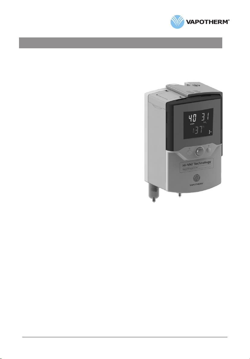
• Vapor transfer cartridge. In the cartridge, blended
gas passes through the lumens of hundreds of parallel
hollow fibers made of a specially developed polymer.
Warm water circulates around the fibers and diffuses
as vapor through the fiber material into the gas stream
flowing through each fiber. Unlike most humidifiers,
there is no direct contact between the water and
gas streams. The gas stream leaves the cartridge
saturated with vapor at the set temperature.
Note: Use only approved cartridges from Vapotherm Inc.
Page 8 Precision Flow Hi-VNI Instructions for Use 3101477-01-EN Rev B
Air Inlet
Water Inlet
Water Outlet
Air Outlet
Page 9
Section 3 Principles of operation
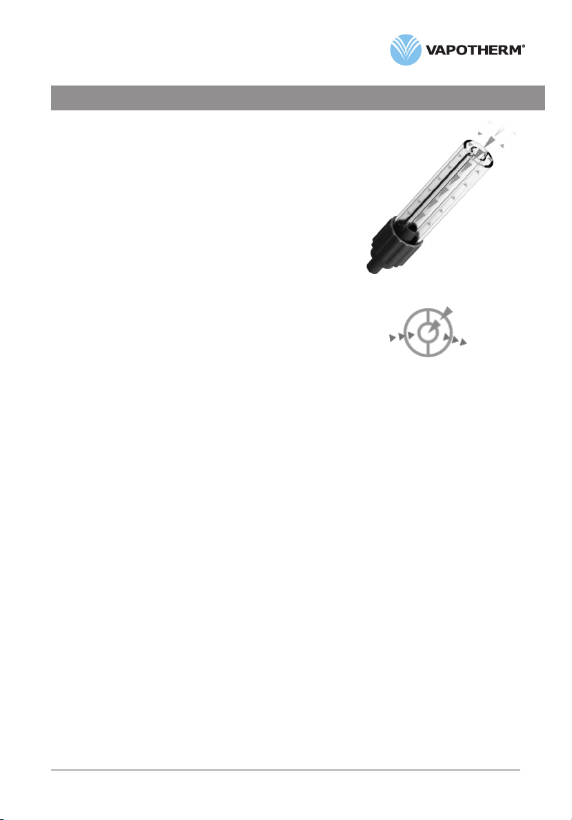
• Patient delivery tube. The warmed humidified gas
passes through the center of a triple-lumen heated
delivery tube. The center lumen is surrounded by two
outer lumens circulating warmed water to maintain
the temperature of the inner lumen and to minimize
rain- out. A proprietary short nasal cannula is
connected to the end of the delivery tube and passes
the humidified breathing gas to the patient’s nares. It
is normal for non-DEHP PVC tubing to appear slightly
cloudy, or yellow, especially during longer use or
when operated at higher temperatures.
• Disposable water path. The disposable water path
houses a water reservoir, pump, connections for
the vapor transfer cartridge and delivery tube, and
sensor interfaces to the main unit. Water is pumped
past a heater plate through the outer lumens of the
delivery tube. Returning water passes through the
outer jacket of the specially designed vapor transfer
cartridge where some water is lost as vapor to the
gas stream. There is no direct contact between water
and gas flows. The water then returns to the pump
reservoir. Heater power automatically maintains
the set temperature. Water flows into the circuit
from the sterile water supply to replace evaporative
losses in the vapor transfer cartridge. Air is purged
to atmosphere from the circulation via a hydrophobic
filter membrane.
Electronic Medical Record (EMR) System Integration
Warm Wa ter
Flow
Cross-secti on of Tubing
Breathing
Gas
Warm Wa ter
Ret urn
The Precision Flow® Hi-VNI provides outbound interface capabilities that facilitate integration
with Electronic Medical Record (EMR) Systems. The Precision Flow® Hi-VNI does not connect
directly to EMR Systems. Interface of the Precision Flow® Hi-VNI to EMR systems requires the
services and technology of an EMR Integrator. The EMR Integrator provides integration into
the institution’s physical network with interface hardware (wired or wireless device adapters)
and a communication translation engine (Gateway) to translate the Precision Flow® Hi-VNI’s
data output to specific EMR system formats, then validate the functionality of the connection.
Bernoulli Systems (formally Nuvon) and Capsule are the Vapotherm recommended 3rd party
integrators.
See Section 5 for a description of the modes of operation.
Precision Flow Hi-VNI Instructions for Use 3101477-01-EN Rev B Page 9
Page 10
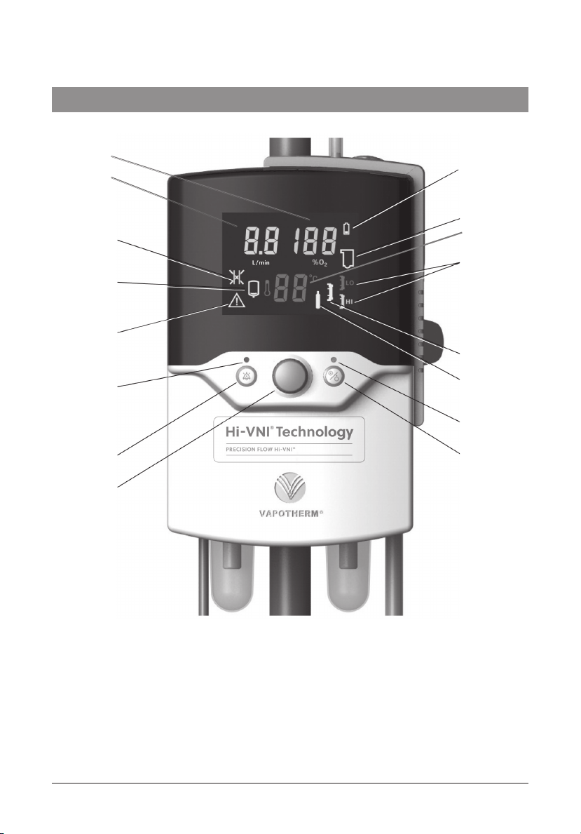
Section 4 Controls, displays, & connections
16
15
13
12
11
1
2
14
3
4
10
9
8
1. Battery low or charging
2. Disposable water path faulty or absent
3. Vapor transfer cartridge type
4. Vapor transfer cartridge fault
5. Gas supply fault
6. Run/Stop Status LED
7. Run/Standby button (see note)
8. Setting control knob
9. Alarm mute button
10. Alarm muted LED
11. General fault
12. Water out
13. Blocked tube
14. Temperature Display
15. Flow Display
16. Oxygen % Display
5
6
7
Note:The Precision Flow® Hi-VNI has no ON/OFF switch. Plug the unit into a wall outlet to
keep the battery fully charged.
Page 10 Precision Flow Hi-VNI Instructions for Use 3101477-01-EN Rev B
Page 11
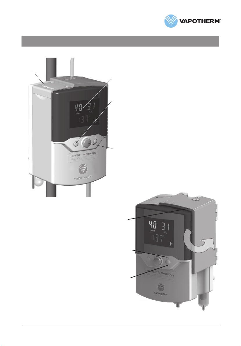
Section 4 Controls, displays, & connections
Front view
1
2
3
4
5. Hinged door:
• Opens to install or remove disposable
water path
6. Status light:
• Amber flashing in Sleep mode
• Amber solid in Standby mode
• Flashing green in Run mode when output
does not match settings
(e.g. during warmup)
• Steady green in Run mode when unit is
operating normally
7. Run/standby button:
• Press to start unit after water, DPC,
and gas are connected
1. Folding carrying handle
2. Multi-function display:
• Shows set values for oxygen %, flow
and temperature
• Icons indicate alarm conditions and
device status
3. Alarm mute:
• Press to silence alarms for up to
2 minutes
• LED indicates one or more alarms
are muted
4. Setting control knob:
• Press to select which variable to adjust
• Rotate to adjust to parameter value
• Press again to set value
5
6
7
Precision Flow Hi-VNI Instructions for Use 3101477-01-EN Rev B Page 11
Page 12

Section 4 Controls, displays, & connections
1
2
3
5
6
7
4
Rear view
1. Hinged door
8
• Open to install or remove disposable water path
2. Vent
3. Access panel for O2 sensor with nurse call/EMR connector (see note)
4. Pole clamp
5. Power cord connection and fuse holder
6. DISS or NIST oxygen connection
7. DISS or NIST air connection
8. Gas inlet filters and traps
Note: Using a permanent marker, write an expiration date on the O2 sensor cell
that is one year from the date it is removed from its packaging. Computers or
other equipment should not be plugged into the Nurse Call/EMR Port. Only Nurse
Call / EMR cable (PN# 3100897) shall be used.
Page 12 Precision Flow Hi-VNI Instructions for Use 3101477-01-EN Rev B
Page 13

Section 4 Controls, displays, & connections
Docking station for disposable water path
WARNING:
Heater plate may
be hot!
Arrows show locations of optical sensor ports.
Do not scratch or scrub the ports.
Do not apply organic solvents or bleach.
Section 5 Modes of operation
Mode Action Indicator light color
Sleep Display in sleep mode, no gas flow Amber
Standby Display flashes 00; parameters can be adjusted, no gas flow Amber
Run Warming to set point temperature, gas flow
Unit operating at set point, gas flow
See Appendix for a description of the software operating modes.
Precision Flow Hi-VNI Instructions for Use 3101477-01-EN Rev B Page 13
Flashing green
Solid green
Page 14

Section 6 Initial assembly
Certain accessories must be installed in the Precision Flow® Hi-VNI unit before it can be used.
These will normally be supplied in a separate package from the main unit as some are countryspecific. The power cord plugs into the IEC60320-compliant receptacle on the rear panel.
WARNING: Do not position the Precision Flow® Hi-VNI so that it is difficult to operate the
disconnection of the device.
6a. Oxygen sensor installation
CAUTION: The oxygen sensor is in a sealed
package. Un-sealing the package admits oxygen
to the sensor, which should be replaced after 1
year. Do not open the package until the unit is to
be used. Write the expiration date on the oxygen
sensor cell.
1. Loosen three (3) captive screws from the access
panel. Pull the panel away from the unit.
2. Insert the threaded end of oxygen sensor into port,
and screw into place. Sensor should be hand-tight only.
Do not use tools.
3. Plug sensor cable into connector. Replace cover.
When replacing cover, be certain not to pinch cables.
Do not over-tighten screws.
6b. Inlet gas filter trap assemblies.
Gas inlet filters and traps are supplied in a separate box with the O2 sensor and must be
installed before first-time use. The inlet filter and trap assemblies have a quick-disconnect
fitting which connects to the main unit, and a gas fitting for either an oxygen or an air hose.
Note: The quick-disconnect tubes for the oxygen and air filters are different sizes, so that they
can not be connected incorrectly.
Oxygen Sensor Access Panel
WARNING: Never attempt to run the Precision Flow® Hi-VNI unit without the gas inlet filters.
Particles in the inlet gas flow will cause irreparable damage to the mass flow sensors.
Installing the gas inlet filters
1. Push the filter assembly firmly into the correct connector opening until it is fully engaged
and it clicks. The filter can rotate but not pull out. Filter bowls should be vertical (glass
side down) when in use.
Removing gas inlet filter assembly from main unit
Note: It is not normally necessary to remove the inlet filter and trap assemblies (unless
performing preventative maintenance), but shipping and packing are easier if the filters are
detached first.
1. Press the filter assembly into the main unit.
2. Hold the locking ring in place and push it back against the main unit backplate.
3. Pull the filter assembly straight out.
Page 14 Precision Flow Hi-VNI Instructions for Use 3101477-01-EN Rev B
Page 15

Section 7 Setting up
7-1. Hang the sterile water supply from hook on
Vapotherm approved roll stand.
7-2. Attach the unit to Vapotherm approved roll stand
below lowest point of the sterile water supply.
NOTE: The Precision Flow® Hi-VNI oxygen and air supply
inlet fittings are gas-specific to ensure correct connection.
WARNING: Unit weighs 10.6 lb.(4.81kg) To prevent
possible injury or damage from falling, it must be
securely fixed to a Vapotherm approved roll stand,
with the base of the unit not more than 40” (102cm)
above the floor. Fixed rail supports may also be used.
Use with Vapotherm approved roll stands.
7-3. Connect oxygen and air supply hoses to correct
inlets, then connect them to the wall outlets.
7-4. Connect power cord.
7-5. Open the bags containing the disposable water path,
vapor transfer cartridge, and delivery tube, and
assemble them as follows:
7-5-1. Remove the rubber plugs from the vapor transfer cartridge.
Install a high or low-flow vapor transfer cartridge in disposable waterpath as shown.
The vapor transfer cartridge may be inserted either way up. Align the vapor transfer
cartridge ports with the disposable water path openings and press firmly into place.
Pole
clamp
Power
cord
Oxygen
A High Flow Vapor Transfer Cartridge is shown below. It is indicated with a
REF: PF-VTC-HIGH and blue caps. High Flow Cartridges are for flow rates of 5-40 L/min.
A Low Flow Vapor Transfer Cartridge is shown below. It is indicated with a
REF: PF-VTC-LOW, red caps and the addition of two black stripes. Low Flow
Cartridges are for flow rates of 1-8 L/min.
Precision Flow Hi-VNI Instructions for Use 3101477-01-EN Rev B Page 15
Page 16

Section 7 Setting up
7-5-2. Connect the delivery tube to the disposable water path as shown.
Press firmly into place.
7-6. Inserting disposable patient circuit:
7-6-1. Open door to expose the docking station.
7-6-2. Hold disposable patient circuit by its handle,
with the delivery tube downward as shown.
7-6-3. Slide disposable patient circuit downward into
the docking station until it stops.
7-6-4. Press down firmly so there is no gap between the
bottom of the Disposable Water Path and the docking
station floor.
7-6-5. Close door.
NOTE: If the door does not close easily, check that the cartridge is installed correctly
and the disposable water path is fully inserted into the docking station.
CAUTION: Do not remove the disposable patient circuit while the unit is operating
Page 16 Precision Flow Hi-VNI Instructions for Use 3101477-01-EN Rev B
Page 17

Section 7 Setting up
7-6-6. General Guidelines
After connecting to the sterile water supply and unclamping the water inlet tube make sure
water is flowing into the disposable patient circuit (DPC). Wait approximately 90 seconds (or
180 seconds if using a hard water bottle) before pressing the Run/Standby button. If screen is
dark, press any button or turn the setting control knob prior to placing in Run mode. Uncoil and
straighten the delivery tube to allow water to more easily flow into the DPC. If air pockets are
observed, gently tap the delivery tube to remove the air. Insufficient water flow may lead to a
temperature out of range alarm. Holding the distal end of the delivery tube below the Precision
Flow® Hi-VNI unit may further assist with water flow into the DPC.
After pressing the Run/Standby button, confirm that water is properly circulating through the
machine by making sure the patient delivery tube is warm across the entire length. If good
circulation cannot be confirmed, check that the water flow is not obstructed by air bubbles in the
water inlet tube connected to the water supply, or in the patient delivery tube. Gently tap and
wiggle the tubing, or lift it up and down in order to remove any air seen in the lines.
Reference Section 12 of the Precision Flow® Hi-VNI Instructions for Use for information regarding
alarms. Additional alarm information:
If a medium priority Water Out Alarm occurs, this may be due to the sterile water supply being
empty, an obstructed inlet tube, or accumulation of air within the DPC. If the sterile water supply
is empty, replace sterile water supply. If the inlet tube is obstructed, straighten the inlet tube. If
necessary, remove and reseat the DPC to ensure that the DPC is fully seated in the Precision
Flow® Hi-VNI unit. Press Run/Standby button to restart the unit. If alarm persists, disconnect
patient from therapy.
The DPC may be used up to 30 days. Circuit life may be less than 30 days, especially when
running at higher flow rates and temperatures which may reduce the useful life of the Vapor
Transfer Cartridge. This typically results in the sterile water bag filling up with air and/or a
cartridge fault alarm occurring due to gas bubbles in the water path.
After addressing any alarm condition, especially those involving an obstruction of the gas or
water flow, check all connections for leaks and make sure the Vapor Transfer Cartridge (VTC) is
fully seated into the DPC.
Precision Flow Hi-VNI Instructions for Use 3101477-01-EN Rev B Page 17
Page 18

Section 7 Setting up
WARNING: Use high–flow cartridge for flows 5-40 L/min and low-flow cartridge for flows 1-8 L/min.
7-7. Plug in power cord, and check that all the display indicators light up. The Precision Flow®
Hi-VNI performs a self-test:
• all icons and numeric displays light up for a few seconds
• internal sensors and control systems are checked
• if no faults are detected the unit enters STANDBY mode
• “Water Out” icon indicates there is no water in the disposable water path
• status LED is amber (solid)
7-8. The Precision Flow® Hi-VNI unit has three controls.
Run/Standby Button – Places the unit into run or standby mode.
Setting Control Knob - Allows you to adjust the parameters.
Alarm Mute Button – Will intermittently silence alarms
and also dims the display panel.
The Precision Flow® Hi-VNI has three modes. Those are
Sleep, Standby, and Run. In Sleep mode, the unit will
have a blank screen and a flashing amber light showing.
The unit cannot be started from sleep. (Note: If the
unit is in Standby mode and there is no user interaction
with the unit for 5 minutes, the unit automatically enters
Sleep mode).
To put the unit in Standby (from Sleep mode), simply
rotate the blue Control Setting Knob to illuminate the
display. You will see the three parameters of Flow,
percent oxygen, and Temperature. There will also
be a corresponding vapor transfer cartridge indicator
on the lower right hand side which will identify what
type of disposable patient circuit is in place
(Blue/High or Red/Low).
To enter Run Mode (from Standby mode), with the screen illuminated,
simply press and release the Run/Standby Button.
The machine will give a series of 10 beeps, and begin to power up. At this point the
small light above the Run/Standby Button will change from Amber to flashing Green.
During this start up, you will also see two amber alarm indicators illuminated.
This is normal and is part of the Precision Flow® Hi-VNI start up self-test.
7-9. Push or rotate the control setting knob in either direction to light up the display in
STANDBY mode.
7-10. Press the Mute button to change between bright and dim display
(this function is only available if no alarms are active).
7-11. To connect the sterile water supply, remove spike cap and disinfect spike with 70-90%
isopropyl alcohol or equivalent. Firmly insert spike into spike port of the sterile water supply,
avoiding direct hand contact. Unclamp the water inlet tube so that water (>200 ml)
flows into the disposable water path and the “Water Out” alarm icon clears.
(*Wait approximately 90 seconds (or 180 seconds if using a hard water bottle)
before pressing the Run/Standby button).
Page 18 Precision Flow Hi-VNI Instructions for Use 3101477-01-EN Rev B
Run/Standby
button
Page 19

Section 7 Setting up
7-12. Press Run/Standby button to start gas flow, pump and heater.
Press twice if the display is initially blank (once to wake the unit up, and again
to put the unit into run mode). Check that the unit beeps while it tests the disposable
water path and pump (see Notes below).
7-13. If all tests are passed the unit enters RUN mode. Water circulates and fills the delivery
tube. The three numeric displays for flow, temperature and oxygen % display initial
factory settings or the last settings used. The Status LED flashes then shows
continuously green when the unit reaches desired temperature.
NOTES on startup:
• When the Run/Standby button is pressed, the unit enters a detection mode. A prompt
sounds and the disposable water path icon flashes for approximately five seconds.
In this mode the unit inspects the disposable water path to confirm that: a vapor
transfer cartridge is present; the disposable water path is present; and the water level
is correct. Power is then applied to the water pump. After five seconds the unit checks
that the water pump has started and is running at the correct speed.
• If the “water out” icon is displayed and accompanied by an alarm, place unit in standby
and allow DPC to fully prime. Press Run/Standby button.
• Purging of air bubbles from the circulation cannot be seen, because the gas escapes
through a membrane at the top of the DWP, not into the water container.
• Clamp the inlet tube to stop the flow of water into disposable patient circuit
whenever the unit is in standby mode.
To adjust settings: See section 8 (Adjustments)
For alarms and troubleshooting: See section 12 (Alarms)
Section 8 Adjustments
Flow rate, oxygen %, and temperature are all adjusted
using the setting control knob in the center
of the front panel.
8-1. To enter Adjustment mode, press and release
the setting control knob. One of the three
parameters will flash to show that it is selected
for adjustment. Press the knob repeatedly to
cycle the active selection through flow rate,
oxygen %, and temperature.
8-2. To change the selected variable, rotate the
knob until the desired value is displayed.
Press the knob again to enter this value and
select the next variable.
8-3. If the knob is not rotated for five (5) seconds,
the unit returns to the normal Run mode or
Standby mode. To re-enter Adjustment mode,
press the knob again. Rotating the knob has
no effect unless one of the settings has been
selected and one of the displayed values is flashing.
Precision Flow Hi-VNI Instructions for Use 3101477-01-EN Rev B Page 19
Setting control knob
Page 20

Section 8 Adjustments
NOTES on settings:
• When gas inlet pressures are less than 40 psi (276 kPa) the full specified range of flows
and oxygen mixtures is not available. The Precision Flow® Hi-VNI detects the actual inlet
pressures and calculates the range of values that can be achieved. An alarm sounds if
the operator attempts to make settings outside this range.
• If oxygen is not connected, the blender setting will be fixed at 21%. If air is not connected
the setting is fixed at 100%. An audio signal sounds if the operator attempts to set any
other value.
• If a HIGH-FLOW cartridge is installed the flow cannot be set below 5 L/min.
• If a LOW-FLOW cartridge is installed the flow cannot be set above 8 L/min.
NOTES on adjustment:
• Transient temperature changes may occur after rapid changes in flow settings.
• During warmup the temperature display shows the actual temperature of the gases being
delivered, not the set value.
• In Run mode the display shows the current set values for flow rate, oxygen %, and
temperature.
• The setting control knob is sensitive to speed. Rotate quickly for large increments and
slowly for small increments.
• If the unit is completely powered down (disconnection of AC power), then the unit will
return to default settings.
Section 9 Connecting to patient
9-1. Wait for the unit to reach 33°C before placing the cannula (applied part) on the end of
the patient delivery tube. The flashing green Status LED becomes steady when the set
temperature is reached.
9-2. Check water level, temperature display, gas flow rate, and oxygen percentage.
9-3. Size cannula (applied part) to patient by ensuring that nasal prongs do not fit tightly into
nares (1/2 the diameter of the nares).
9-4. Attach correct sized cannula (applied part) for the patient and vapor transfer cartridge
onto the delivery tube. Adjust the flow to the desired rate and fit the cannula to the
patient. See appendix table for cannula flow rates. DPC flow ranges are shown in the
table below:
Cartridge Cannula type Operational flow rates
High Flow
Low Flow
Patients weighing less than 3 Kg
must always be put on Low Flow
*Pediatric small cannula is intended to deliver flows from 1-20 L/min
Page 20 Precision Flow Hi-VNI Instructions for Use 3101477-01-EN Rev B
Adult, pediatric & small adult,
pediatric small*
Premature, solo, neonatal,
infant, intermediate infant,
pediatric small*
5-40 L/min
1-8 L/min
Page 21

Section 9 Connecting to patient
WARNINGS:
• Always follow aseptic technique (including proper hand washing and avoiding direct
hand contact with connection points) when setting up the Precision Flow® Hi-VNI and
Standard Precautions when placing on a patient.
• Cannula prongs should not obstruct more than 50% of the nares of the patient.
• Change nasal cannulas when soiled. Replace cannulas according to clinical judgment
and hospital policy but not to exceed 30 days continuous use.
• To reduce the risk that the patient may aspirate condensed water from the breathing
circuit, regularly observe the patient and output of the patient interface for excess water,
and if detected remove patient interface from the patient. Water in the center lumen
can result from condensation or due to a leak from the outer lumens that surround the
breathing circuit.
NOTES:
• The Vapotherm approved interface should be connected to the patient only when the unit
has reached at least 33°C.
• Droplets of condensation may appear at the end of patient delivery tube while unit is
warming up. This is normal and will stop within a few minutes when set temperature is
reached and the cannula is fitted to the patient.
• Some condensation around the nose is possible. In addition, a high moisture level may
mobilize mucus from nose and sinuses. Make sure patient has a supply of tissues.
• The unit should not be placed in Standby mode for extended periods of time. For
pauses in therapy, keep the unit in RUN mode, remove cannula from the patient, and
set the parameters to the lowest available setting. To reinitiate therapy, before the
cannula is placed on patient, clear accumulated condensation.
Section 10 Operations: General Guidelines
WARNINGS:
• Never connect the unit to a patient until it reaches at least 33°C. Allow the unit to warm-up
to purge condensate and prevent patient discomfort due to cold or partly humidified gas.
• Condensation in the cannula may occur in certain ambient conditions at flow rates less
than 5 L/min (low flow cartridge) or less than 10 L/min (high flow cartridge). To minimize
condensation it is recommended not to set the temperature higher than 34°C, if using flow
rates less than 5 L/min.
10-1. Check that water is properly circulating through the disposable by making sure the patient
delivery tube is warm across the entire length. If good circulation cannot be confirmed,
check that the water flow is not obstructed by air bubbles in the patient delivery tube.
10-2. Check that the patient delivery tube will not be occluded by the patient’s position or
moving bed structures.
10-3. Take precautions to minimize cooling of the unheated cannula by trying to maintain
contact with the patient’s skin and insulating the exposed portion of the cannula
with bedding.
10-4. During operation the door should be closed.
10-5. Check inlet gas traps for contaminates and press valve to empty any condensate,
if present.
10-6. Check that nothing blocks the vent on the back of the unit.
Precision Flow Hi-VNI Instructions for Use 3101477-01-EN Rev B Page 21
Page 22

Section 11 Changing the disposable patient circuit
The disposable patient circuit, consisting of the disposable water path, vapor transfer
cartridge and delivery tube, is marked for 30 days single patient use. Change
disposable patient circuit when visibly soiled or contaminated. Replace according to
clinical judgment and hospital policy but not to exceed 30 days continuous use.
11-1. Stop the unit by pressing the Run/Standby button and hold for 2 seconds.
Unit will enter Standby mode.
11-2. Clamp the water inlet tube connected to the sterile water supply.
11-3. Open the door to expose the disposable water path.
11-4. Lift the disposable patient circuit out of the Precision Flow® Hi-VNI unit and discard in
accordance with institutional guidelines.
11-5. Wipe down the docking station with Super Sani-Cloth®. The Precision Flow® Hi-VNI must
always be cleaned and disinfected between patients.
NOTE: If the door does not close easily, check that the cartridge is installed correctly
and the disposable water path is fully inserted into the docking station.
WARNINGS:
• The heater plates on the docking station and
disposable water path may be hot !
• Universal precautions and aseptic technique must be used in
handling the disposable parts.
11-6. Open a new vapor transfer cartridge, delivery tube and disposable water path.
11-7. Install the vapor transfer cartridge and delivery tube in the disposable water path as
described in Section 7 (Setting up).
CAUTIONS:
• The sensor windows in the docking station must not be scratched or damaged. If
necessary, wipe down the docking station with 70-90% isopropyl alcohol wipes or
Super Sani-Cloth®. Never use sharp instruments or abrasive cleaners to clean
windows.
11-8. Slide the disposable patient circuit into the docking station and close the door.
11-9. Hang new sterile water supply on the hook of the Vapotherm approved roll stand.
11-10. Wipe the spike on the water inlet tube with 70-90% isopropyl alcohol and insert into
spike port of the sterile water supply.
11-11. Re-start the unit.
Page 22 Precision Flow Hi-VNI Instructions for Use 3101477-01-EN Rev B
Page 23

Section 12 Alarms
The essential performance of the device consists of proper humidification at high flow rates,
heating of water to physiologic levels, and delivery of appropriate FiO2. The User needs to
appropriately respond to alarms and perform required maintenance, to ensure the essential
performance of the device is maintained.
Fault conditions are indicated by icons displayed on the front panel and by audio signals.
• Unless indicated otherwise, alarms will self-clear when the fault condition is corrected.
• The MUTE button will silence low priority alarms for 2 minutes and medium priority alarms
for 20 seconds (except for Blocked Tube alarm, which can only be muted for 5 seconds or
less while the alarm resets). General fault alarms cannot be muted.
• Gas flow continues during many alarm conditions -except when the O2 supply gas pressure
is outside specified range.
• An amber LED above the Mute button indicates that one or more alarms are muted.
FLOW display in liters/min OXYGEN % display
Battery low or
charging (not
indicative of
charge level)
Disposable
water path faulty
or absent
L /min
Blocked
tube
Water
out
General
fault
TEMPERATURE display
Low flow Vapor
transfer cartridge
installed
Vapor transfer
cartridge fault (low
flow or high flow)
High flow Vapor
transfer cartridge
installed
Gas supply fault
ALARM TONE PRIORITIES
• MEDIUM PRIORITY alarms require immediate attention and are indicated by rapid
intermittent tones (fast triple beeps).
• LOW PRIORITY alarms require attention as soon as reasonably possible and are
indicated by infrequent intermittent tones (slow double beeps).
In addition to the medium and low alarms, the Precision Flow® Hi-VNI emits the following
audio signals:
• single dull tone that sounds when the unit switches from run to standby mode
• single high pitched beep whenever you press the control setting knob
• low pitched buzz when you try to change a setting that cannot be changed or when
alarm conditions prevent entering the run mode
• five slowly repeating single beep during disposable water path testing when entering
run mode.
Precision Flow Hi-VNI Instructions for Use 3101477-01-EN Rev B Page 23
Page 24

Section 12 Alarms
Technical Alarms - Alarm Table
GENERAL FAULT ALARMS: Failures in the control or measurement systems will cause a General
Fault alarm indicated by this icon accompanied by the Temp display showing numbers between 50 & 84 (error
codes) and dashes in the O2 and Flow displays. When an error code is displayed, gas delivery is stopped. The
user needs to monitor the treatment and respond to general fault alarms. See the alarm icon descriptions below
for specific alarm conditions and associated information. General Fault alarms cannot be silenced with the
mute button. To reset, first disconnect the unit from AC power and then press the Run/Standby button. With the
exception of O2 sensor replacement, the unit must be repaired by an approved service facility. Replacement of
other components outside of an approved service facility could result in unacceptable risk.
Alarm icon Audio Signal Indicates Cause Action
General fault
illuminated and
flow parameter
showing " - - "
(flashing)
General fault
illuminated and
flow parameter
showing " - - "
(flashing)
General fault
illumnated and O
parameter
showing " - - "
(flashing)
General fault
illumnated and O
parameter
showing " - - "
(flashing)
Blocked tube
(flashing)
Water out Medium
Page 24 Precision Flow Hi-VNI Instructions for Use 3101477-01-EN Rev B
Medium
Priority
Cannot be
muted
Medium
Priority
Cannot be
muted
Medium
Priority
2
Cannot be
muted
Medium
Priority
2
Cannot be
muted
Medium
Priority
Mutes only
during brief
reset period
Priority
Malfunction of
sensor or
control system
Desired flow
cannot be
achieved
O2 sensor fault Depleted or
Desired Oxygen
% cannot be
maintained
High back
pressure
No water in
disposable water
path. Gas flow
continues without
heating or water
circulation.
Internal
component
failure
Insufficient
supply pressure
for desired
flow rate
defective O2
sensor
Interruption of
oxygen supply,
flow or pressure
Obstructed or
kinked cannula/
delivery tube,
incorrect cannula
for flow rate, or
DPC improperly
seated
Sterile water
empty, or
obstructed inlet
tube.
Check gas supply.
If not corrected,
disconnect patient.
Unplug AC power,
press and hold Run/
Stand-by button for 3
seconds to clear the
alarm, send for service.
Increase supply
pressure
Unplug AC power,
press and hold Run/
Standby button for 3
seconds to clear the
alarm. Replace O2
sensor. Restart unit.
Verify oxygen supply
system has gas and
pressure
Clear obstruction,
check cannula type,
re-install DPC
Replace water bag or
straighten inlet tube.
Restart unit. If alarm
persists, disconnect
patient from therapy.
Page 25

Section 12 Alarms
Other Alarms - Alarm Table
Alarm icon Audio
Indicates Cause Action
Signal
Disposable
water path
(flashing)
Battery
charging
(steady)
Battery
(flashing)
Cartridge fault
Cartridge type None Indicates type of cartridge installed (low or high flow).
Medium
Priority
None The internal battery backup is not fully charged. The unit would
Medium
Priority
Medium
Priority
Low
Priority
None Cartridge and/
Disposable
water path faulty
or not detected.
Unit will not run.
not run on battery for the full rated time in the event of a power
failure. No action is necessary.
The unit is
running in
BATTERY
mode. Gas flow
and blending
continue without
heat or water
circulation.
Cartridge and/
or DPC not
detected. Unit
will not run
Gas bubbles in
water circulation.
Unit continues to
operate.
or DPC not
detected.
Not an alarm.
Disposable
water path
defective, not
properly seated
or not installed.
AC power is
disconnected
RUN mode:
faulty sensor
or cartridge not
detected.
Excessive
gas diffusion
through
cartridge fibers.
STANDBY
mode: missing
cartridge.
If disposable water path
is present, place unit into
Standby, remove and
replace disposable patient
circuit to reset detector.
Restart Unit.
Reconnect AC power.
Disconnect patient.
Remove disposable patient
circuit. Check cartrridge
installation. Check sensor
windows are clean.
Disconnect patient. Place
unit into Standby. Replace
disposable patient circuit
including water path,
cartridge & delivery tube.
Remove disposable
patient circuit. Check
cartridge installation.
Gas supply (flashing)
Gas supply
(continuous and
flow rate numeric
display flashes)
Precision Flow Hi-VNI Instructions for Use 3101477-01-EN Rev B Page 25
Medium
Priority
Medium
Priority
Gas supply
pressure outside
4-85 psi (28-586
kPa) range. Unit
will not operate.
Selected flow
cannot be
provided from
current gas
supply.
Gas supply is
disconnected
or exhausted.
Inlet gas
pressure too
low for
selected
flow rate.
Check gas supply and
correct as necessary.
Increase gas pressure or
decrease flow setting.
Page 26

Section 12 Alarms
Other Alarms - Alarm Table
Alarm icon Audio
General fault
illumnated and
temperature
parameter
showing " - - "
(flashing)
Temperature numeric
display flashes
Signal
Medium
Priority
Cannot be
muted
Medium
Priority
Indicates Cause Action
Temperature out
of range.
Temperature 2°
> set point
Temperature 2°
< set point
Overheating
or temperature
sensor
malfunction.
User enters
set point
much lower
than previous
temperature.
Very low water
temperature
after bag
replacement.
Cannot be corrected by
user: disconnect patient.
Unplug AC power, press
and hold Run/Standby
button for 3 seconds to
clear the alarm, send
for service.
Silence alarm and wait for
temperature to drop.
Silence alarm and wait for
temperature to rise.
Page 26 Precision Flow Hi-VNI Instructions for Use 3101477-01-EN Rev B
Page 27

Section 13 Shut down
13-1. Stop the unit by pressing the Run/Standby button and hold for 2 seconds. Unit will enter
Standby mode.
13-2. Clamp the water inlet tube.
13-3. Open the hinged door, remove the disposable water path with vapor transfer cartridge
and delivery tube attached by sliding it upwards out of the docking station.
13-4. Discard all disposables according to hospital guidelines.
13-5. Disconnect unit from AC power.
Note: The Precision Flow® Hi-VNI has no ON/OFF switch. Plug the unit into a wall outlet to
keep the battery fully charged.
CAUTION: Even a fully charged battery will lose its charge over a period of weeks
when the unit is not connected to an AC source. It is recommended that the unit is
connected to AC for at least two hours once a month to maintain battery charge.
Section 14 Routine maintenance
14.a The internal backup battery should be replaced every two years. Contact Vapotherm for
further information.
14.b Oxygen sensor
The oxygen sensor (part no. 3003011) should be replaced annually. It is accessible by removing
a panel at the back of the unit, and can be changed in a few minutes by the user or biomedical
engineer. Use only Vapotherm approved parts.
To replace oxygen sensor:
1. Loosen three (3) captive screws from the access panel.
Pull the panel away from the unit.
2. Disconnect the cable connector: grasp with pliers and
pull straight back.
3. Unscrew the sensor body from its housing. Insert new
sensor and screw in.
4. Plug in cable and replace cover. When replacing
cover, be certain not to pinch cables. Do not
over-tighten screws.
5. Apply label to indicate when replacement is due or write
the date with a permanent marker.
CAUTION: Sensor should be hand-tight only. Do not use tools.
Oxygen sensor access panel
Precision Flow Hi-VNI Instructions for Use 3101477-01-EN Rev B Page 27
Page 28

Section 14 Routine maintenance
14.c Gas inlet filters and traps
Replace the gas inlet filters (part no. 3003034) every 6 months. For ordering information, please
contact Vapotherm.
14.d Fuses
The mains fuses (two GMA - 3A F250 V, 5 x 20mm) are located next to the power cord inlet.
Ensure that the unit is unplugged before replacing fuses. Use a small flat blade screwdriver to
pry open the fuse compartment door to access fuses.
NOTE: Vapotherm Preventative Maintenance Kits include all parts required for annual (PM Kit
P/N 3100904) and biennial (PM Kit P/N 3100906) routine maintenance.
Section 15 Cleaning and disinfection
The entire disposable patient circuit is disposable and no disinfection is required. The main unit,
including the docking station for the disposable water path should be wiped down with Super
Sani-Cloth®. Unplug the Precision Flow® Hi-VNI while cleaning and disinfecting. The Precision
Flow® Hi-VNI must always be cleaned and disinfected between patients. Follow the steps below
to ensure a clean and disinfected device.
• Wipe down the main unit with Super Sani-Cloth®.
• Examine for visible soil. If visible soil is present, use a brush (e.g. Spectrum M16
brush) to remove visible soil.
• Wet the main unit with another Super Sani-Cloth®. Keep the surface wet for at least six
minutes. Use additional Super Sani-Cloth® if needed.
The Precision Flow® Hi-VNI must be cleaned and disinfected with Super Sani-Cloth®. In
addition, if hospital procedures require, the following may be used: 70-90% isopropyl alcohol,
2% (maximum) Chlorine cleaning solution (Sodium Hypochlorite), 6% (maximum) Hydrogen
Peroxide cleaning solution, Caviwipes TM, AF3 Germicidal, Incidin® OxyWipe, Bacillol® 30
Tissues, Clinell® Alcohol Wipes, or Tuffie Disinfectant Wipes-Cloth®.
NOTE: The transparent sensor ports in the docking station must be clean. Refer to
Section 4 for a drawing of the docking station with arrows pointing to the location of the
sensor ports. Visually examine the sensor ports for a transparent finish to confirm cleaning
has been effective. The unit will not operate if the sensors do not receive a clear signal.
CAUTION: Do not use organic solvents or abrasive cleaners. Hypochlorite solutions liberate
toxic gases such as chlorine when acidified or heated. The reaction with ammonia or with
substances that can generate ammonia can produce chloramines which are also toxic and
have explosive potential. Do not expose the surface of the heater plate on the Precision
Flow® Hi-VNI unit to concentrations of Chlorine solution (Sodium Hypochlorite) for a
prolonged period of time, as this may cause surface damage to the metal plating.
If not cleaned properly with approved cleaners, the Precision Flow® Hi-VNI unit will fail
to operate correctly.
Page 28 Precision Flow Hi-VNI Instructions for Use 3101477-01-EN Rev B
Page 29

Section 16 Specifications
PHYSICAL CHARACTERISTICS
Dimensions:
Height 11.5”(300mm), width 8”(200mm), depth 7”(180mm), excluding Vapotherm approved
roll stand clamp and gas inlet filters.
Weight:
10.6 lb (4.81 kg) without disposable patient circuit
Circulating Water Volume:
Mounting:
Rear mounted clamp fits Vapotherm approved roll stands up to 1.5”(38mm) diameter.
Gas Connections:
Standard non-interchangeable fittings for medical air and oxygen.
FUSES: (Qty 2) GMA 3A F250 V 5mm x 20mm
SYSTEM REQUIREMENTS
Power:
100-240 VAC, 50-60Hz, < 350VA during warm up, approx. 80VA in steady state
(depends on flow rate and temperature).
Back-up power:
4.8V nickel-metal hydride battery pack.
Gas supply:
Medical air and oxygen at inlet pressures between 4 and 85 psi (28-586 KPa).
NOTE: The full range of flows and oxygen percentage is available only if both gases are
present at inlet pressures of at least 40 psi (276 kPa). Unit is calibrated at Vapotherm
using 100% O
2
Water:
Sterile water for inhalation in pre-filled sealed container.
400 ml approx. including delivery tube and vapor transfer cartridge.
Recommended water change interval based on flow rate and operation at 37°C.
Flow Rate Average water usage per
day
1-10 L/min 650 ml 500 ml / 12 h
10-20 L/min 1300 ml 500 ml / 8 h
20-30 L/min 2000 ml 1000 ml / 12 h
30-40 L/min 2600 ml 1000 ml / 8h
Precision Flow Hi-VNI Instructions for Use 3101477-01-EN Rev B Page 29
Recommended
Change Interval
Page 30

Section 16 Specifications
PERFORMANCE
Temperature:
Range- 33 to 39°C at exit from the delivery tube, adjustable
Resolution- 1°C
Accuracy- ± 2°C
Warm up time:
± 2°C of 33°C set point < 5 minutes (at ambient 23°C)
NOTE: Time required to heat is dependent on the temperature set point, flow rate and
ambient temperature. Due to normal system variation, it is possible not all combinations
of temperature and flow rate may be achieved, in particular when set to the higher settings.
Humidification:
Minimum of 12 mg/L
Oxygen percentage:
Range- 21 to 100% O
Accuracy- ± 2%
Resolution- 1%
NOTE: At flow rates less than 3 L/min, for 22% & 23% oxygen blend, the delivered oxygen
is 21%. At flow rates less than 3 L/min, for 98% and 99% oxygen blend, the delivered
oxygen is 100%.
2
Page 30 Precision Flow Hi-VNI Instructions for Use 3101477-01-EN Rev B
Page 31

Section 16 Specifications
PERFORMANCE
Flow rate resolution:
Accuracy- ± 10% or 0.5 L/min whichever is greater
STANDARDS
Designed to conform to the following standards:
IEC 60601-1
IEC 60601-1-2:2014
UL60601-1
CSA C.22.2/No. 60601.1
AS/NZS 3200.1.2
EN60601-1
ISO/IEC 80601-2-74
ISO 11195
ISTA-2A
ENVIRONMENTAL
Operating
Ambient temperature: 18-30°C
Ambient relative humidity: 20-90% RH non-condensing
Ambient Pressure: 86 kPa to 108 kPa – Not to be used in hyperbaric conditions
Altitude up to 1,948 m (6,392 ft)
Storage and Shipping
Ambient temperature: -10 - +50°C
Ambient relative humidity: 20-90% RH
ALARM SOUND PRESSURE RANGES
Medium Priority Alarm
47 dB measured 1m from unit
Low Priority Alarm
45 dB measured 1m from unit
EXPECTED LIFE
The Precision Flow® Hi-VNI has an expected life of 5 years with typical use of roughly
150 days per year. Actual life will vary depending on whether typical use is greater
than 150 days per year, quality of gas supplies, cleaning with proper agents, operating
per Instructions for Use instructions and cautions, and the timely execution of routine
maintenance. More frequent use, dirty and or wet gas supplies, or the use of organic or
abrasive cleaners will reduce the expected life.
Precision Flow Hi-VNI Instructions for Use 3101477-01-EN Rev B Page 31
Page 32

Appendix
Standard Cannula
Size Part No.
Premature MN1100A 1.5 8
Neonatal MN1100B 1.5 8
Infant MI1300 1.9 8
Intermediate Infant MI1300B 1.9 8
SOLO cannula SOLO1300 1.9 8
Pediatric Small MPS1500 1.9 20
Pediatric/Adult Small MP1500 2.7 40
Adult (base) MA1700 4.8 40
Audio Tone Characteristics
Tone Type
Medium Priority 660 3 200 200 2.5
Low Priority 660 2 200 200 22
Run/Standby Transition 440 1 - 30 -
Encoder Know Press 880 1 - 30 -
User Interface Error 220 1 - 100 -
Self Test 660 5 1000 50 -
DWP Detecting 660 1 - 100 0.9
Fo
(Hz)
Prong Outer
Dia. (mm) Max. Flow
Pulses
per Burst
Pulse
Spacing
(ms)
Pulse
Duration
(ms)
Inter-Burst
Interval (s)
Page 32 Precision Flow Hi-VNI Instructions for Use 3101477-01-EN Rev B
Page 33

Appendix
Software operating modes
The diagram illustrates the operating modes for the unit.
• Immediately on connection to AC power a POST (Power-On Self-Test) is run to verify
proper function of subsystems, sensors and actuators in the Precision Flow® Hi-VNI.
• On successfully completing the POST the unit enters STANDBY unless there is a test
failure, when the system alarms, enters FAULT mode and cannot be started.
• The Precision Flow® Hi-VNI enters RUN mode from STANDBY when the RUN/STANDBY
button is pressed. Normal operation starts. The pump, heater and gas flow proportioning
systems start. Sensors and alarms are active and flow, temperature and oxygen % can
be set.
• To return to STANDBY, the RUN/STANDBY button is pressed again and held for
2 seconds.
• If AC power is disconnected when the unit is in RUN mode it enters BATTERY mode.
If the battery is fully charged, gas mixing and metering continues for at least 15 minutes,
but water is not circulated or heated. When the battery is discharged the unit enters the
POWER OFF mode.
• If AC power is disconnected in STANDBY, the unit enters POWER OFF mode.
Precision Flow Hi-VNI Instructions for Use 3101477-01-EN Rev B Page 33
Page 34

Appendix
Electromagnetic Compatibility (EMC)
The Precision Flow® Hi-VNI is suitable for the electromagnetic environment of typical commercial or hospital settings.
During the immunity testing described below the Precision Flow® Hi-VNI continued to deliver proper humidification at high flow
rates, heating of water to physiologic levels, and delivery of appropriate FiO2.
WARNINGS:
• Portable RF communications equipment (including peripherals such as antenna cables and external antennas) should be used no closer than
30 cm (12 inches) to any part of the Precision Flow® Hi-VNI System, including cables specified by Vapotherm. Otherwise, degradation of the
performance of this equipment could result.
• Use of this equipment adjacent to or stacked with other equipment should be avoided because it could result in improper operation. If such use is
necessary, this equipment and the other equipment should be observed to verify that they are operating normally.
• Use of accessories, transducers and cables other than those specified or provided by the manufacturer of this equipment could result in
increased electromagnetic emissions or decreased electromagnetic immunity of this equipment and result in improper operation.
Guidance and manufacturer’s declaration - electromagnetic emissions
The Precision Flow® Hi-VNI is intended for use in the electromagnetic environment specified below.
The customer or the user of the Precision Flow® Hi-VNI should assure that it is used in such an environment.
Emissions test Compliance Electromagnetic environment- guidance
RF emissions CISPR 11 Group 1 The Precision Flow® Hi-VNI uses RF energy only for its internal function. Therefore, its RF
RF emissions CISPR 11 Class A The Precision Flow® Hi-VNI is suitable for use in all establishments other than domestic.
Harmonic emissions
IEC 61000-3-2
Voltage fluctuations/ flicker
emissions IEC 61000-3-3
The Precision Flow® Hi-VNI is intended for use in the electromagnetic environment specified below. The customer or the user of the Precision Flow®
Hi-VNI should assure that it is used in such an environment.
Immunity Test Compliance Level Electromagnetic Environment - Guidance
Electrostatic discharge (ESD)
IEC 61000-4-2
Electrical fast transient / burst
IEC 61000-4-4
Surge IEC 61000-4-5 ± 1 kV differential mode
Voltage dips, short interruptions and voltage variations
on power supply input lines
IEC 61000-4-11
Power frequency (50/60 Hz)
magnetic field IEC 61000-4-8
NOTE: UT is the A/C. mains voltage prior to application of the test level.
±8kV air
±15kV contact
±2kV for power supply lines
+/- 1 kV I/O cables
+/- 2kV line to ground
>95% UT Dip for .5 Periods
at <5% UT Test Level.
60% UT Dip for 5 Periods at
40% UT Test Level.
30% UT Dip for 25 Periods
at a 70% UT Test Level.
4 A/m Power frequency magnetic fields should be at levels characteristic of a typical
emissions are very low and are not likely to cause any interference in nearby equipment.
N/A
Warning: This equipment/system is intended for use by healthcare professionals only. This
equipment/system may cause radio interference or may disrupt the operation of nearby equipment.
It may be necessary to take mitigating measures, such as re-orienting or relocating the Precision
N/A
Flow® Hi-VNI or shielding the location.
Electromagnetic Immunity
Floors should be wood, concrete or ceramic tile. If floors are covered with synthetic
material, the relative humidity should be at least 30%.
Mains power quality should be that of a typical commercial or hospital environment.
Mains power quality should be that of a typical commercial or hospital environment.
Mains power quality should be that of a typical commercial or hospital environment.
If the user of the Precision Flow® Hi-VNI requires continued operation during power
mains interruptions beyond that provided by the battery, it is recommended that the
Precision Flow® Hi-VNI is powered from an uninterruptible power supply.
location in a typical commercial or hospital environment.
Electromagnetic Immunity
The Precision Flow® Hi-VNI is intended for use in the electromagnetic environment specified below. The customer or the user of the Precision Flow®
Hi-VNI should assure that it is used in such an environment.
Immunity Test Compliance Level Electromagnetic Environment - Guidance
Conducted RF
IEC 61000-4-6
Radiated RF
IEC 61000-4-3
3 Vrms
6 Vrms in ISM and amateur
radio bands
3 V/m
The Precision Flow® Hi-VNI is suitable for the electromagnetic environment of typical
commercial or hospital settings.
Page 34 Precision Flow Hi-VNI Instructions for Use 3101477-01-EN Rev B
Page 35

Appendix
Recommended separation distances between portable and mobile RF communications equipment and the Precision Flow® Hi-VNI
Max Output Power (Watts) Separation (m) 150kHz to 80MHz
0.01 .12 .12 .23
0.1 .37 .37 .74
1 1.17 1.17 2.33
10 3.69 3.69 7.38
100 11.67 11.67 23.33
Warranty
Vapotherm expressly warrants, for a period of one (1) year from the date of shipment by Vapotherm to the initial purchaser of
the Precision Flow® Hi-VNI device (“Customer”) that the Precision Flow® Hi-VNI device shall meet the specifications set forth
in the applicable official operating instructions for use provided with each Precision Flow® Hi-VNI device (the “Instructions”).
The sole remedy for this warranty is that Vapotherm shall, at its sole option, either refund, repair or replace any or all of any
Precision Flow® Hi-VNI device that is defective at no cost to the Customer. Vapotherm shall pay any shipping charges required
in repairing or replacing any part or all of a Precision Flow® Hi-VNI device during the warranty period. Thereafter, shipping
charges shall be paid by the Customer. Customer shall also be responsible for the cost of labor for repairs. This warranty does
not apply to any disposable component to the Precision Flow® Hi-VNI device, including without limitation the disposable patient
circuits and hoses supplied with the Precision Flow® Hi-VNI device.
The warranty set forth herein shall become null and void if: (1) the Precision Flow® Hi-VNI device is not used or serviced in
accordance with the applicable Instructions or any related preventative maintenance instructions provided with the Precision
Flow® Hi-VNI device; or (2) the Precision Flow® Hi-VNI device is opened or tampered with, or if repairs or service are performed
or attempted on the Precision Flow® Hi-VNI device by anyone other than Vapotherm or a Vapotherm-certified service center.
EXCEPT AS EXPRESSLY SET FORTH ABOVE, VAPOTHERM MAKES NO WARRANTY, EXPRESS, IMPLIED, STATUTORY
OR OTHERWISE, WITH RESPECT TO THE PRODUCTS OR ANY OTHER ITEMS PROVIDED BY VAPOTHERM, AND
HEREBY EXPRESSLY DISCLAIMS ANY OTHER FORM OF WARRANTY, INCLUDING, WITHOUT LIMITATION, ANY
WARRANTY OF MERCHANTABILITY OR FITNESS FOR A PARTICULAR PURPOSE. THIS STATED WARRANTY IS
EXCLUSIVE AND IN LIEU OF ALL OTHER WARRANTIES PROVIDED BY LAW.
D=(3.5/V1)(√P)
Separation (m) 80 to 800MHz
D=(3.5/E1)(√P)
Separation (m) 800MHz to 2.5GHz
D=(7/E1)(√P)
For further information contact:
Vapotherm Inc.
100 Domain Drive
Exeter, NH 03833
USA
Phone: 603-658-0011
Fax: 603-658-0181
www.vapotherm.com
May be patented
www.vapotherm.com/patents
RMS – UK Limited
28 Trinity Road
Nailsea, North Somerset BS48 4NU
United Kingdom
Phone: +44-1275-85-88-91
Fax: +44-1275-85-88-91
Technical Support Line
Domestic: 855-557-8276
International: 603-658-5121
TS@Vtherm.com
Precision Flow Hi-VNI Instructions for Use 3101477-01-EN Rev B Page 35
Page 36

Vapotherm Inc.
100 Domain Drive
Exeter, NH 03833
USA
Phone: 603-658-0011
Fax: 603-658-0181
3101477-01-EN Rev B
Page 36 Precision Flow Hi-VNI Instructions for Use 3101477-01-EN Rev B
 Loading...