

Page 1
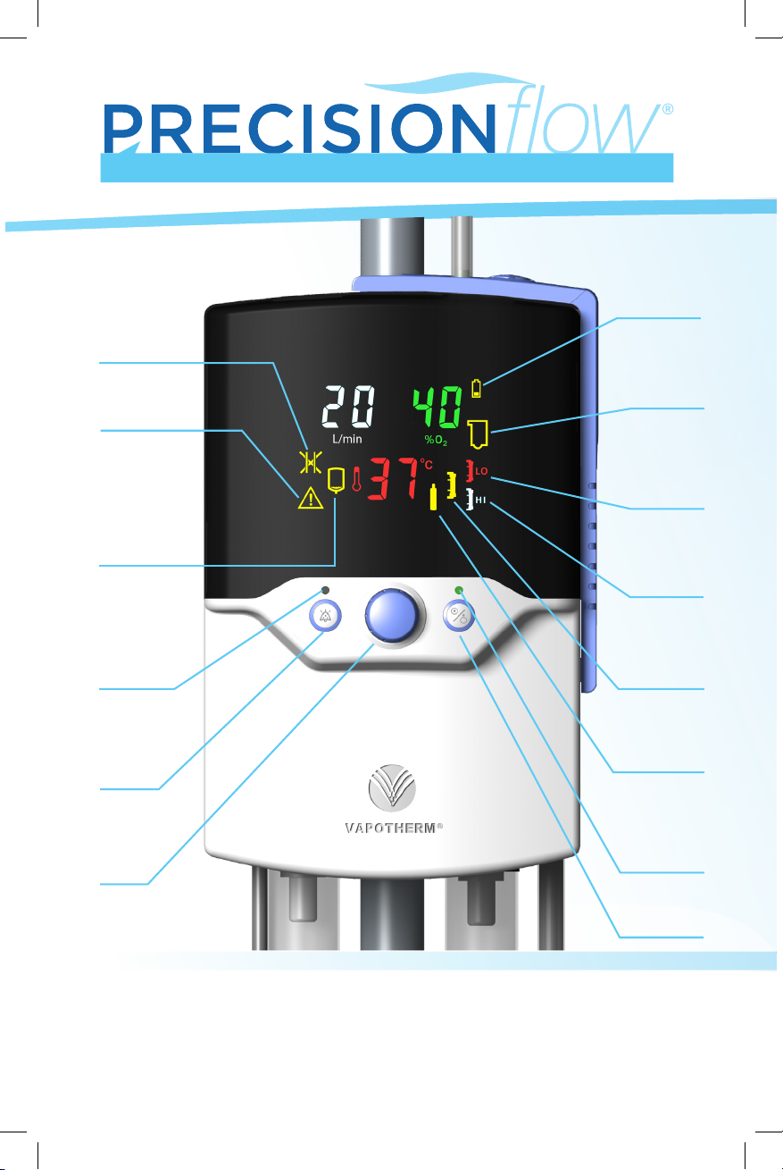
QUICK REFERENCE GUIDE
Battery low
or charging
(not indicative of
charge level)
Blocked tube
General fault
Water out
Alarm mute
LED
Alarm mute
button
Setting
Control
Knob
Disposable
Water Path
faulty or
absent
Low Flow
Circuit
Installed
High Flow
Circuit
Installed
Vapor Transfer
Cartridge fault
Gas supply
fault
Run/Stop
Status LED
Run/ Standby
button
This guide provides you with basic instructions on how to set up and operate
the Precision Flow®. Before operating the Vapotherm Precision Flow®, please
review the Instructions For Use which can be found at our website
www.vapotherm.com and on the USB drive provided in the Start-Up Kit.
Page 2

ALARM ICON WARNING INDICATES CAUSE ACTION
ALARM ICON WARNING INDICATES CAUSE ACTION
Primary Indications:
Precision Flow® is intended for use to add warm moisture to breathing gases from an external source for
administration to a neonate/infant, pediatric and adult patients in the hospital, subacute institutions, and home
settings. It adds heat and moisture to a blended medical air/oxygen mixture and assures the integrity of the
precise air/oxygen mixture via an integral oxygen analyzer. The ow rates may be from 1 to 40 liters per minute
via nasal cannula.
Contraindications: General:
• Not appropriate for patients who are not spontaneously breathing, are unable to protect their airway or have anatomic or
injury induced blockage of the nasal pathway to the nasopharyngeal space
• Not for treating OSA and snoring
• The Precision Flow® is not for eld transport
• The Precision Flow® is MRI unsafe. Do not use it in an MR environment.
Additional patient monitoring including pulse oximetry is necessary if the Precision Flow® is used to give
supplementary oxygen.
Precision Flow® Packaging contains:
Precision Flow® Unit
Power Cord
US ONLY - Air and Oxygen Hoses
Check gas supply. If not
GENERAL FAULT
and
– – IN FLOW
(FLASHING)
Malfunction of
sensor or control
system
Internal
component failure
corrected, disconnect patient.
Unplug AC power, press and
hold Run/Standby button for
3 seconds to clear the alarm,
send for service.
GENERAL FAULT
and
– – IN 0
2
(FLASHING)
O₂ sensor fault
Depleted or
defective O₂ sensor
Unplug AC power, press and
hold Run/Standby button for
3 seconds to clear the alarm.
Replace O2 sensor. Restart unit.
Cannot be corrected by user:
GENERAL FAULT
and
– – IN TEMP
(FLASHING)
Temperature
out of range.
Overheating or
temperature sensor
malfunction.
disconnect patient. Unplug AC
power, press and hold Run/
Standby button for 3 seconds
to clear the alarm, send for
service.
No water in dispos-
WATER OUT
able
water path. Gas ow
continues without
heating or water
Sterile water empty,
or obstructed inlet
tube.
Replace water bag or straighten
inlet tube. Restart unit. If alarm
persists, disconnect patient
from therapy.
circulation.
If disposable water path is
present, place unit into
Standby, remove and replace
disposable patient circuit to
reset detector. Restart unit.
DISPOSABLE
WATER PATH
(FLASHING)
BATTERY
CHARGING
(STEADY)
Disposable water
path faulty or not
detected. Unit will
not run.
Disposable water
path defective, not
properly seated or
not installed.
The internal battery backup is not fully charged. The unit would not run on
battery for the full rated time in the event of a power failure. No action is
necessary.
The unit is running
BATTERY
(FLASHING)
in BATTERY mode.
Gas ow and
blending continues
without heat or
water circulation.
AC power is
disconnected
Reconnect AC power.
Obstructed or
BLOCKED TUBE
(FLASHING)
High back pressure
kinked cannula/
delivery tube, incorrect cannula for
Clear obstruction, check
cannula type, re-install DPC
ow rate or DPC
improperly seated
GENERAL FAULT ALARMS:
indicated by this icon accompanied by the Temp display showing numbers between 50 & 84 (error codes) and
dashes in O₂ and Flow displays. When an error code is displayed, gas delivery is stopped. The user needs to monitor
the treatment and respond to general fault alarms. General Fault alarms cannot be silenced with the mute button.
To reset, rst disconnect the unit from AC power and then press the Run/Standby Button. With the exception of O₂
sensor replacement, the unit must be repaired by an approved service facility.
Failures in the control or measurement systems will cause a General Fault alarm
CANNULA FLOW RATES
CARTRIDGE CANNULA TYPE OPERATIONAL FLOW RATES
High Flow Adult, Pediatric/Adult Small, Pediatric Small* 5-40 liters per minute (L/min)
Low Flow Premature, Neonatal, Infant, Intermediate Infant,
Solo, Pediatric Small*
*Pediatric Small cannula is intended to deliver ow rates of 1-20 L/min
1-8 liters per minute (L/min)
Page 3

ALARM ICON WARNING INDICATES CAUSE ACTION
LO HI
CARTRIDGE
FAU LT
CARTRIDGE
TYPE
GAS SUPPLY
(FLASHING)
GAS SUPPLY
(CONTINUOUS
AND FLOW
RATE NUMERIC
DISPLAY
FLASHES)
TEMPERATURE
NUMERIC
DISPLAY
FLASHES
Disconnect patient. Remove
Cartridge and/or DPC not
detected. Unit will not run.
RUN mode: faulty
sensor or cartridge
not detected.
disposable patient circuit.
Check cartridge installation.
Check sensor windows are
clean.
Disconnect patient. Place
Gas bubbles in water
circulation. Unit
continues to operate.
Excessive gas
diusion through
cartridge bers.
unit into Standby. Replace
disposable patient circuit
including water path,
cartridge & delivery tube.
Cartridge and/or DPC
not detected.
STANDBY mode:
missing cartridge.
Remove disposable
patient circuit. Check
cartridge installation.
Indicates type of cartridge installed (low or high ow). Not an alarm.
Gas supply pressure
outside 4-85 psi
(28-586 kPa) range.
Unit will not operate.
Selected ow can not
be provided from current
gas supply.
Gas supply is
disconnected or
exhausted.
Inlet gas pressure
too low for selected ow rate.
Check gas supply and correct
as necessary.
Increase gas pressure or
decrease ow setting.
User enters set
Temperature 2° > set point
point much lower
than previous
Silence alarm and wait for
temperature to drop.
temperature.
Temperature 2° < set point
Very low water
temperature after
bag replacement.
Silence alarm and wait for
temperature to rise.
INDICATIONS, WARNINGS AND CAUTIONS
Primary Indications:
Precision Flow® is intended for use to add warm moisture to breathing gases from an external source for
administration to a neonate/infant, pediatric and adult patients in the hospital, subacute institutions, and home
settings. It adds heat and moisture to a blended medical air/oxygen mixture and assures the integrity of the
precise air/oxygen mixture via an integral oxygen analyzer. The ow rates may be from 1 to 40 liters per minute
via nasal cannula.
Contraindications: General:
• Not appropriate for patients who are not spontaneously breathing, are unable to protect their airway or have anatomic or
injury induced blockage of the nasal pathway to the nasopharyngeal space
• Not for treating OSA and snoring
• The Precision Flow® is not for eld transport
• The Precision Flow® is MRI unsafe. Do not use it in an MR environment.
Additional patient monitoring including pulse oximetry is necessary if the Precision Flow® is used to give
supplementary oxygen.
Precision Flow® Packaging contains:
Precision Flow® Unit
Power Cord
US ONLY - Air and Oxygen Hoses
Instructions For Use on USB Quick Reference Guide
Air & Oxygen Inlet Particulate Traps with Connectors O2 Sensor cell
Delivery Tube clip
Page 4

DISPOSABLE PATIENT CIRCUIT
• Assemble Disposable Patient Circuit according to provided instructions.
• Open door and install Disposable Water Path into docking station so there is no gap
between bottom of the Disposable Water Path and the Docking Station Floor
• Hang sterile water bag or bottle
• Wipe water spike with alcohol pad or equivalent and insert into sterile water bag
• Allow a minimum of 200ml of water to ll into the Disposable Patient Circuit
• Precision Flow is ready for start up
START UP AND ADJUSTING PARAMETERS
• Install oxygen sensor. Replace sensor annually
• Install gas inlet lters on back with lter bowls vertical (glass side down). Replace gas
inlet lters every six months
• Attach air & O₂ hoses. Plug in power cord
• Rotate the blue Setting Control Knob to illuminate display
• Press in Setting Control Knob to select the parameter and rotate to adjust the value
• Press and release (do not hold) the Run/Standby button once to start
A GREEN light indicates RUN mode (AMBER light indicates STANDBY mode, No Flow)
• Green light will stop ashing once temperature is reached
CONNECT TO PATIENT
• The ashing green LED becomes steady when the set variables are reached
• Place the cannula on the patient. Once the unit has reached at least 33°C, connect to
delivery tube
• The unit should not be placed in Standby mode for extended periods of time. For
pauses in therapy, keep unit in RUN mode, remove cannula from the patient, and set
the parameters to the lowest available setting. To reinitiate therapy, before cannula is
placed on patient, clear accumulated condensate
INTERNAL BATTERY BACK-UP
• The back-up battery is designed for temporary use only, when AC power to the unit
has been interrupted
• The unit will enter into battery mode and will maintain ow and oxygen percentage
for at least 15 minutes
• The battery icon will ash
• Replace battery every two years
• Battery recharges in two hours
SHUT DOWN
• Press the Run/Standby button. Unit will enter Standby mode (No Flow), indicated by
the AMBER light
• Clamp the water inlet tube. Open the door, remove the Disposable Patient Circuit
(includes delivery tube & cartridge) by sliding it upwards out of the docking station
• Discard all disposables according to hospital guidelines
• Disconnect unit from AC power
• Wipe down with Super Sani-Cloth®. In addition, if hospital procedures require, the
following may be used: 70-90% Isopropyl Alcohol, 2% (maximum) chlorine cleaning
solution, 6% (maximum) Hydrogen Peroxide cleaning solution, CaviWipesTM, AF3
Germicidal, Incidin® OxyWipe, Bacillol® 30 Tissues, Clinell® Alcohol Wipes, or Tue
Disinfectant Wipes
VAPOTHERM, INC.
100 Domain Drive
Exeter, NH 03833
T: 603-658-0011
USA
3101540 Rev. A
May be patented. www.vapotherm.com/patents
Technical Support
T: 855 557 8276 Domestic
+1 (603) 658-5121 International
ts@vtherm.com
0297
RMS-UK Ltd.
28 Trinity Road
Nailsea, North Somerset
BS48 4 NU
United Kingdom
 Loading...