


These instructions contain operating information and should be left with the unit.
Resistance Heater Units
Installation & Operation Manual
Edition 6
(For use with Software version 8.0 and subsequent issues)
Installation in countries covered by EC Directives:
This product meets the requirements of the RoHS Directive 2002/95/EEC
This product will meet the requirements of the Low Voltage Safety Directive 2006/95/EEC and the
EMC Directive 2004/108/EEC when installed in accordance with the instructions contained in this
manual.
Failure to comply with these instructions may invalidate the manufacturer's warranty or any
certificate/declaration of conformance requested to be supplied with the unit.

CONTENTS
1.0 Installation. ................................................................................................................................ 4
1.1 Positioning the Vapac LR unit ................................................................................................... 4
1.1.1 Vapac LR unit dimension layout ............................................................................................ 4
1.1.2 LR weights ............................................................................................................................. 7
1.2 Positioning the steam pipes ...................................................................................................... 7
1.2.1 General .................................................................................................................................. 7
1.2.2 Steam Hose Connection ....................................................................................................... 7
1.3 Plumbing Considerations. ......................................................................................................... 8
1.4 Electrical Connections .............................................................................................................. 9
1.4.1 Important E.M.C. Considerations ......................................................................................... 9
1.4.2 Power Supply Connection ................................................................................................... 10
1.4.2.1 Volt free alarm outputs ........................................................................................................ 10
1.4.2.2 Unit control terminals ........................................................................................................... 10
1.4.3 Electrical Connections ......................................................................................................... 11
1.4.4 Cable Entry Provision .......................................................................................................... 11
1.4.5 Vapac Control Circuit Transformer ...................................................................................... 11
1.4.6 RDU Connection.................................................................................................................. 11
1.4.7 Cylinder Electrical demand loads ........................................................................................ 12
1.5 Control Circuit Connections .................................................................................................... 13
1.5.1 Control Circuit Wiring .......................................................................................................... 13
1.5.2 Proportional Control ............................................................................................................ 13
1.5.3 Control Signal Selection ...................................................................................................... 13
1.5.4 On/Off Control ..................................................................................................................... 13
1.5.6 Security Circuit / E.P.O. Shutdown ...................................................................................... 14
1.5.7 Load Shed Option................................................................................................................ 14
1.5.8 Master/Slave System .......................................................................................................... 15
2.0 Start-Up / Operation ................................................................................................................ 16
2.0.1 Start-up check list ................................................................................................................ 16
2.0.2 Start-Up Instructions ............................................................................................................ 17
2.0.3 Commissioning/Start-Up ..................................................................................................... 17
2.0.4 Features of VAPANET Resistance Heater Unit .................................................................. 17
2.1 Service Advice ........................................................................................................................ 18
2.1.1 Cylinder Inspection. ............................................................................................................. 18
2.2.1 Feed Valve with Strainer ..................................................................................................... 19
2.2.2 Drain Pump .......................................................................................................................... 19
3.0 Location of Indicators and Controls ....................................................................................... 20
3.1 Positioning of Indicators and controls on Vapac ® Vapanet ® LR Units. ............................... 20
3.2 Initial Set-up ............................................................................................................................ 21
3.3 Normal Run / Standby / Start-up – No User Intervention Required ........................................ 22
3.4 Fault / Service Indications – Requiring Operator Intervention. ............................................... 23
3.4.1 To Postpone the Sevice: ..................................................................................................... 24
3.4.2 To Service the unit: ............................................................................................................. 24
3.5 Other Options .......................................................................................................................... 25
3.6 Use with LRO unit................................................................................................................ 25
4.0 Trouble-shooting Check List ................................................................................................... 26
5.0 Wiring Diagram ....................................................................................................................... 27
Appendix 1.
A Guide to Positioning Steam Pipes: ................................................................................................. 41
Appendix 2.
A Guide to Positioning Multipipes: ..................................................................................................... 43

Important Installation Points
The unit must be installed to comply with national regulations and/or codes of practice. A qualified
electrician must carry this out.
Ensure at least 1000 mm clear front access to the electrical and steam sections of the cabinet.
Do not locate the cabinet where the ambient temperature around the unit could exceed 35ºC or fall
below 5ºC e.g., an unventilated roof mounted enclosure – see minimum space / ventilation
requirements page 5.
Do not locate the cabinet where a ladder is required for service access as this could make
servicing and cylinder service or exchange hazardous.
Make sure steam line(s) have adequate slope (min 12%) for condensate drainage and use
condensate separators if the pipe is lower than the unit.
Provide adequate support to prevent sags developing in flexible steam lines, w hich can fill w ith
water and create a "trap".
Do not locate vented drain directly under the cabinet.
It is important to select the correct water type, see table on page 8, your water supply company
should be able to provide the required information free of charge.
Important Electrical Connection Items
Before commissioning the unit, check that all electrical (power) connections - including those at
the terminals and contactor are tight.
Check that the transformer primary winding connection is correct for the supply voltage at Vapac
terminals A1 & A2.
The Vapac transformer must not be used to power other equipment.
To comply with EMC aspects see recommendations on page 9.
Use a high-limit humidistat to ensure positive interruption of unit operation when over-
humidification is detected (see p14).
It is important that the control signal connected to terminals 5 & 6 must be referenced to ground at
the control PCB – this can be done by linking either terminal 5 or 6 to terminal 7.
NB if the controller output is referenced to ground, it is important that the “leg” which is
connected to ground at the controller is also connected to ground at the Vapac unit. Grounding
the opposite “leg” will cause damage to the controller and/or the Vapac control PCB.
Important Maintenance Items
Only a qualified electrician should carry out maintenance.
The boiler contains hot water, and must be drained before any maintenance is carried out on the
steam section. This should be done prior to isolating the power, and removing the front access
panel
ESD SENSITIVE DEVICES USED ON PCB. ENSURE ANTI-STATIC PRECAUTIONS ARE TAKEN
WHEN REMOVING OR REPLACING PCB’S.

1.0 Installation.
1.1 Positioning the Vapac LR unit
1.1.1 Vapac LR unit dimension layout
Do’s
Do mount the unit as close to the steam distribution
pipe(s) as possible.
Do mount the unit at a height convenient for reading the
display window.
Do ensure adequate side ventilation (min 80 mm).
Do ensure adequate service access to the front of the unit
(min 1000 mm).
Do ensure adequate service access below the unit (min
1000 mm).
Do ensure that the holes in the rear top panel remain
unobstructed to allow a free flow of air see fig 1.
Do use the marking on the side of the carton as a template
to mark the mounting hole positions.
Do remove the cylinder, if necessary, to access the
mounting holes in the back of the steam section.
Do use M6 projecting type wall bolts or equivalent to
mount the unit in position.
Do mount units with RDU’s so that steam pipe discharge is
above head height.
Do leave minimum gap between the top of an RDU and
the ceiling as per table in fig 3.
6
165
Don’ts
Don’t mount the unit close to sources of strong electro-
magnetic emissions e.g. variable speed lift motor
drives, kVa transformers etc.
Don’t mount the unit in an unventilated enclosure.
Don’t mount in a position requiring ladder access to the
unit.
Don’t mount the unit behind a false ceiling or other
situation where an unusual malfunction (e.g. water
leak) would cause damage.
Don’t mount the unit in an area which will be hosed down.
Don’t install the unit where the ambient temperature can
exceed 35oC; or fall below 5oC.
Don’t mount the unit inside a cold-room or other place
where temperature and humidity conditions can cause
condensation on electrical components.
Don’t mount the unit where the sound of a contactor
opening/closing and water flow in a pipe would be
unacceptable e.g. libraries, private apartments, etc.
Don’t position an RDU to discharge directly over
expensive equipment, desks or stored materials
305
6
.
Gland Plate
120 x 120
NB Entry hole for
Gland Plates approx
105 x 90
299
360
55
810
62
186
Steam Outlet
330
165
305
70
520
73555
Wall mounting
fixing centres
D = Drain discharge 35mm pipe.
D
F
F = Water feed ¾” BSP male
connection
Fig 1 LR5 & LR5P to LR 30 &
LR30P units with or without
RDU fitted.
52
90

Fig 2 LR5 & LR5P to LR 30 & LR30P RDU
Within the area of H1 or H2 above the unit nothing must protrude out from the
wall, as this will effect the natural ventilation path of the Unit.
Fig 3 Clearances around LR units.
LR UNIT A B L H min H1 H2
LR5 & LR5P 377 205 80 1000 500 200
LR10 & LR10P 377 205 80 1000 500 250
LR20 & LR20P 435 205 80 1000 500 500
LR30 & LR30P 602 205 80 1000 500 750

Fig 4 LR40 & LR40P to LR 60 & LR60P
610
190
360
55
6
176
346
6
55
360
322
Steam outlet pipes position.
610
990
810
505
190
73555
31.1"(790)
70 850
Gland Plate
120 x 120
NB Entry hole for
Gland Plates approx
105 x 90
152
D = Drain discharge
35mm pipe.
F = Two water feed ¾”
BSP male connection
Note:- RDU units
cannot be fitted to LR40 &
LR40P to LR60 and
LR60P units
20.5"(520)
468
62
FF
D
237
343
343
LR40, LR40P, LR50, LR50P, LR60, and LR60P units
have the same minimum recommended dimension as
follows:
Note:
L, H & H1 refer to dimensions shown in Fig 3 on page 5.
Wall mounting
fixing centres
Gland Plate
120 x 120
NB Entry hole for
Gland Plates approx
105 x 90
L 100
H 1000
H1 600

7
1.1.2 LR weights
The unit dry weight is the delivered unit with no
water in unit, the wet weight is the operational
weight when the unit is running . The RDU weight
must be added to the unit weight if fitted on top of
the Resistive unit.
Resistive model Dry Kg Wet Kg RDU Kg
LR5 and LR5P 34 48 6
LR10 and LR10P 35.5 49.5 10
LR20 and LR20P 39 65.5 12
LR30 and LR30P 40 66.5 14
LR40 and LR40P 72.5 125.5 NA
LR50 and LR50P 73.5 126,5 NA
LR60 and LR60P 74.5 127.5 NA
1.2 Positioning the steam pipes
1.2.1 General
Steam pipes should be positioned as shown below,
allowing a minimum rate of fall back to the unit of
12% to allow the free flow of condensate back to the
unit. If the above fall is not possible, then
condensate separators must be fitted as shown in
figure 1.
The position of the steam pipe or multipipe in a airconditioning system relative to other items such as
bends, filters, heat exchangers, etc., is critical. The
steam pipe must not be located closer to such item,
than the entrainment distance, and must be decided
by the design engineer responsible for the project.
Do's
Do obtain project engineer's instruction/drawing for
chosen location of pipe
Do obtain project engineer's instruction/drawing for
pipe position relative to the top & bottom of the
duct (or sides if airflow is vertical.
Do check if alternative slope of Ø35mm pipe has
been specified requiring rotation of pipe in its
socket before installation.
Do use bracket/lug on the end of Ø54mm pipes for
extra support.
1.2.2 Steam Hose Connection
Do's
Do use Vapac steam hose or well insulated copper
pipe.
Do keep steam hose as short as possible (under 2m
for max efficiency).
Do arrange to have a vertical rise immediatel y over
the unit of 300mm.
Do use the full height available between the unit and
steam pipe to provide maximum slope (min 1220% for condensate to drain back to the steam
cylinder (or down to a condensate separator).
Always provide a continuous slope.
Do provide adequate support to prevent sagging
a) fit pipe clips every 30-50cm
or b) support straight lengths on cable trays or
in heat resistant plastic pipe.
Do ensure radius hose bends are fully supported to
prevent kinks developing when in service.
Do add extra insulation to steam hose for longer
runs (2m-5m) and in cold ambient conditions to
avoid excess condensate and reduction in
delivered output.
Don'ts
Don't allow steam hose to develop kinks or sags.
Don't include horizontal runs or 90
steam line.
o
elbows in the
Steam Distribution Pipe requirement
Resistance Heater
Unit Model
35mm ∅ Pipe No.
54mm ∅. Pipe No.
* Duct Pressure Pa. +2000
* For systems with a duct pressure over +1000 Pa. It may
be necessary to fit a suitably sized trap in the water feed
line between the Vapac tundish and the feed drain
manifold to ensure water can enter the cylinder when it is
empty.
LR05
LR10
LR05P
LR10P
1
-
LR20
LR30
LR20P
LR30P
-600
LR40
LR50
LR60
LR40P
LR50P
LR60P
-
1
+2000
-600
Flexible Steam
Pipe.
-
2
No Sags!
Flexible Steam
Pipe.
Distance to first
bend.
R min for 35 ∅ Pipe = 250mm
R min for 54 ∅ Pipe = 500mm
VAPAC
HUMIDIFIER
35 or 54 mm
copper or
stainless steel
steam pipe with
Insulation.
Flexible pipe coupling to
connect Steam pipe to Duct
pipe coupling length to allow
for line movement and
expansion. Coupling clamp
with Hose clips each end.
Fig 6
35mm ∅ Pipe Selection
Duct width
B mm
320-470
470-620
620-770
770-920
920-1070
1070-1200
In-duct Length
L mm
300
450
600
750
900
1050
For guidance on positioning of steam pipes see
Appendix 1.
For guidance on use of Multipipes see Appendix
2.
54mm ∅ Pipe Selection
Duct width
B mm
700-950
950-1450
1450+
In-duct Length
L mm
(Kg)
650 (1.8)
900 (2.2)
1400 (3.2)

8
1.3 Plumbing Considerations.
1.3.1 Cold water supply.
General
The Resistance Heater range of units is capable o f
operating with a range of water quality ra w mains or
de-mineralised/de-ionised. The water supply should
be within the following limits:-
Conductivity 0 – 1000µS
PH 7.3 – 8.0
Silica 0
Pressure of between 1 - 8 bar.
Maximum chloride level 170 ppm
Water Supply rates
1.70 l/min
1.70 l/min
2.00 l/min
2.50 l/min
4.00 l/min
4.50 l/min
5.00 l/min
LR05
LR10
LR20
LR30
LR40
LR50
LR60
LR05P
LR10P
LR20P
LR30P
LR40P
LR50P
LR60P
Do’s
Do install a stop-valve/Shut-off valve and a strainer
close to the unit.
Do provide a water supply with sufficient pressure
and pipe size to ensure an adequate flow rate to
all units connected to the system.
Do use the water connection with nylon nut
provided.
ALL Dimensions in mm
A
B
C
D
F
K
L
M
N
Single Cylinder Units 5-30kg/h
Twin Cylinder units 40-60kg/h
H
G S V
Fig 7
Water type Selected
De-mineralised < 50
De-ionised 50 – 100 < 80
Softened 100 – 200 80 – 100
Potable (Low conductivity) 200 – 300 100 – 150
Potable (Med. conductivity) 300 – 500 > 150
Potable High conductivity > 500
Conductivity
range µS
Max. Chlorine
level ppm
Generally the water type will be selected by the
conductivity levels, however they should be
modified as shown, e.g. conductivity of 75µS and
chlorine level of 85 ppm the correct setting is
Softened”.
Don'ts
Don’t use a wrench or other tool to tighten the water
supply connection - the nylon nut and rubber
washer provided, should only require tightening
by hand to effect a seal. If water seepage occurs,
undo the nut to wipe the washer clean and reseat it.
1.3.2 Drain connection
General
Do's
Do ensure metal drain and supply water pipe work is
grounded electrically close to the unit (a
ground/earth stud is positioned on the under side
of the cabinet.
Drain capacity per cylinder
= pump discharge rate of max 16.8 l/min at 50 Hz.
Power supply 17.2 l/min at 60 Hz.
Do’s
Do use copper or plastic pipe rated for 100
Do arrange to discharge drain water from the unit
into a trapped and vented drain at a position
where flash steam rising from the drain line vent
will not pose a problem for the Vapac or other
equipment.
Do provide adequate fall for the drain pipework to
allow free flow of water drained from each unit.
Do ensure drain line pipe size will accommodate
water being drained at the same time from all the
Vapac units which are connected to it.
KEY: A Tundish Fill-cup
B Steam Cylinder
C Feed Drain Manifold
D Drain Pump
F Feed Solenoid Valve
G Water Connection ¾” BSP.
H Flexible hose ¾” BSP.
K 35∅ Steam Hose coupling and Hose
Clips.
L 35∅ copper or plastic Drain for 110°C
Water with supports.
M Tundish
N U-trap side exit.
S Optional Strainer
V Isolation stop cock
.
o
C.

9
1.4 Electrical Connections
Important Power Connection Information
Vapac 24V and 9 V secondary Transformer Primary supply connections:
Vapac units are wired to allow connection to alternative site Voltages.
Make the following simple checks before connecting the power supply:Move the RED connection on the VAPANET transformer primary winding circuit to the
position marked with the supply Voltage t hat is to be connected between VAPANET
power terminals A1 and A2.
The transformer primary circuit terminal positions are clearly marked:- 200V, 230V,
380, 415 & 440V. If the actual (measured) site voltage is 400v the preferred
tapping is 380V. The transformer is fitted below the Drain tray, and is accessible by
Note:
24 V a.c. Control circuit -
9 V a.c. PCB Circuit -
Transformer Primary Circuit And RDU.
230V ac Pump Supply. -
removing two screws and the cover, which should be slid it towards you.
6.3 A 20 mm (T – Time Lag) fuse (Pt.No. 1080093)
Echelon PCB (Pt.No.1150630).
2 A 20 mm (F - Quick blow) fuse (Pt No. 1080099) mounted on the VAPANET
Echelon PCB (Pt, No. 1150630).
Two fuses protect the control circuit on Single cylinder units F1 2.0A (slow blow)
(Pt. No. 1080095) mounted in fuse-terminal holder protects Primary transformer
and RDU unit if fitted. F2 500 mA 20 mm (F - Quick blo w) fuse (Pt No. 1080054)
mounted in fuse-terminal holder protects Transformer Primary a nd Pump or both
pumps if two pumps are fitted.
The pump or pumps on twin cylinder units are fed from the main transformer via a
230 volt auto winding. The pumps are protected by fuse F1 and F2 above feeding
the transformer primary.
1.4.1 Important E.M.C. Considerations
Use a dedicated, earthed metal conduit for both the
control signal cable and the security circuit cables
along their entire length - they may share the same
conduit where practicable. The earth must be made
by "metal-to-metal" contact and should be a good
RF (Radio Frequency) earth.
The control and security circuit connections should
be run in screened cable with the screen g rounded
at the VAPANET end (onto the electrical section
back panel). The screen should be maintained as
close as possible to the cable ends and any tail
between the screen and the earth point must be
kept short (50 mm maximum).
Control Cable / Security Circuit
Conduit Entry Arrangement
Electrical section metalwork
All metal surfaces which come
into contact with each other,
must be free of paint, grease,
dirt, etc., thereby ensuring a
good low impedance R.F.
(Radio Frequency) path to
ground.
Control Cable / Security Circuit
Cables to control terminals
Outer insulation
mounted on VAPANET
Screening Arrangement
Tail to be kept short
(less than 50mm)
Screen left intact
Earthed back panel
Metal conduit

1.4.2 Power Supply Connection
The unit requires the following connections as shown in
the diagram below
10
1.4.2.1 Volt free alarm outputs
The unit has connections for volt free alarm outputs these
are on the three double terminals next to the main power
input terminals.
The top terminals are for unit volt free fault alarm as
follows:
The bottom terminals are for unit volt free run signal as
follows:
542 common for fault alarm
543 Normally closed when no fault
544 Normally open when no fault
545 Common for run signal
546 Normally closed when unit is in
standby or fault (not running)
547 Normally open when unit is in standby
or fault (not running)
If the unit is part of a master slave system or
network, the run & fault outputs can be selected (via
keypad & display) as either network (system) or unit
only. This is selectable at Service Engineers Level,
in the Engineering Menu, in the window “Fault/Run
Scope”. The default is “network”. It is possible to
get both alarm & Run indication in all units: Single
cylinder units will give this indication if the service
interval has expired; Twin Cylinder & Networked
units will give this indication if the service interval
has expired or if the master cylinder is operating and
any slave cylinder (or cylinders) are in fault.
1.4.2.2 Unit control terminals
For unit control and network termination see
section 1.5 the terminal layout is shown.

11
1.4.3 Electrical Connections
The wiring to the Vapac should be done by a
qualified electrician. The external overcurrent
protection and wiring should comply with the
appropriate Regulations and Codes of Practice
Important: Make sure the connection to the primary
Voltage winding of the Vapac transformer matches
the supply Voltage which is to be connected
between Vapac terminals A1 & A2.If the actual
(measured) site voltage is 400v the preferred
tapping is 380V
.
A fused disconnect/isolator or MCB should be used
to disconnect the supply from all electrodes
simultaneously.
This must be sized to suit the total maximum
phase/line current of the unit and should be located
adjacent to the Vapac cabinet or within easy reac h
and readily accessible.
In Vapac VAPANET units terminals 1, 2 and 3 are
for the power supply connections as indicated in the
diagrams below.
Twin cylinder units’ have terminals for the
connection of two power supply input circuits. On
twin cylinder units’ this allows individual external
protection of each steam cylinder. Fused
disconnect/isolator or MCB provision must be linked
to ensure both 3 phase supply inputs are
disconnected simultaneously.
Notes:-
1. All units must have a PE earth connection connected to the units terminal.
2. Unit with N.A. in the following tables means NOT AVAILABLE there is not a unit available to run at the voltage
and phases shown. Please check that the correct model reference is ordered and installed, for the low or high
voltage required, and at the desired steam output.
3. Standard design is for 50 Hz. Supplies. Design for 60 Hz. Also available - 60 Hz. Supply must be specified with
order as the standard pump is only 50Hz.
FOR FULL ELECTRO-MAGNETIC COMPATIBILITY A NEUTRAL CONNECTION IS REQUIRED FOR ALL
PROPORTIONAL UNITS AS INDICATED IN THE CONNECTION DIAGRAMS ON THE FOLLOWING PAGES.
RDU Connection
The three type’s of RDU are for various voltages and phase without neutrals connections that can be made to the Microvap unit. Please refer
to the Microvap connection diagram on the following three pages as to which type of unit is required. On twin cylinder units two fan circuits as
shown below one for each cylinder will be in the RDU unit.
RDU electrical load
Model RDU05LR RDU09LR RDU20LR RDU30L
Number of fans 2 3 3 5
Fan voltage 230 v 230 v 230 v 230v
Each fan current 50Hz (60 Hz) 115 mA (105 mA) 115 mA (105 mA) 115 mA (105 mA) 115 mA (105 mA)
RDU total load current 50Hz (60 Hz) 225 mA (210 mA) 345 mA (315 mA) 345 mA (315 mA) 575 mA (525 mA)
200 – 250 V 1Ph. N + earth
200 – 250 V 2Ph. + earth
.
1.4.4 Cable Entry Provision
Cable glands must be used to ensure cables are
held securely at the entry position. All Vapac
cabinets are equipped with a removable gland-p late.
The installing electrician should remove this and
take it to a work-bench to drill for the required cable
gland size.
1.4.5 Vapac Control Circuit Transformer
The internal control circuit of the Vapac unit
operates at 24Vac - the transformer secondary is
set at 24V.
As standard the Vapac VAPANET includes a
transformer with alternative primary winding options
200V, 230, 380, 415, and 440V and requires on site
adjustment to match it to the Voltage connected to
Vapac terminals A1 and A2.
The transformer also has a 9V secondary tapping
which provides power to the VAPANET 1150630
PCB.
Important: The Vapac transformer must NOT be
used to power other equipment or the warranty will
be invalidated.
1.4.6 RDU Connection
Vapac terminals 25 & 26 are included to provide a
230Vac electrical supply for the fan motor in the
RDU (Room Distribution Unit) .
Note: The 230Vac at terminals is derived from the
incoming electrical supply to the Vapac. If the local
supply cannot provide 230Vac (example 400V No
Neutral supply) it will be necessary for a transformer
to be fitted in the RDU as indicated below.
380 – 440 V 2Ph + earth
TRANSFORMER
PRIMARY
380 – 440 V
SECONDARY
210 – 250
V

pply
g
r
r
12
1.4.7 Cylinder Electrical demand loads
5 K
/hr Cylinder 10 Kg/hr Cylinde
Voltage V 200 230 250 200 230 200 230 380 415 440
Nominal cylinder size Kg/hr 5 5 5 10 10 10 10 10 10 10
Electrical Supply Ph+N Ph+N Ph+N Ph+N Ph+N 3Ph 3Ph 3Ph 3Ph 3Ph
No. of elements 1113333333
Element Resistance ohms 13.7 13.7 13.7 20.9 20.9 20.9 20.9 20.9 20.9 20.9
Element connection direct direct direct Par/star Par/star DELTA DELTA STAR STAR STAR
Element Matrial
Incoloy 800 Incoloy 800 Incoloy 800 Incoloy 800 Incoloy 800 Incoloy 800 Incoloy 800 Incoloy 800 Incoloy 800 Incoloy 800
Full load Current A 14.6 16.8 18.2 28.7 33.0 16.6 19.1 10.5 11.5 12.2
Power rating Kw 2.92 3.861 4.562 5.742 7.593 5.742 7.593 6.909 8.240 9.263
Max. Output Kg/hr 3.96 5.24 6.19 7.79 10.3 7.79 10.3 9.37 11.17 12.56
Fuse Rating/phase A20202032402025202020
Supply cable terminals mm
2
4 4 4 16161616101010
20 Kg/hr Cylinder 30 Kg/hr Cylinde
Voltage V 200 230 380 415 440 200 230 380 415 440
Nominal cylinder size Kg/hr 20 20 20 20 20 30 30 30 30 30
Electrical Supply 3Ph 3Ph 3Ph 3Ph 3Ph 3Ph 3Ph 3Ph 3Ph 3Ph
No. of elements 6666666666
Element Resistance ohms 20.9 20.9 20.9 20.9 20.9 13.7 13.7 13.7 13.7 13.7
Element connection DELTA DELTA STAR STAR STAR DELTA DELTA STAR STAR STAR
Element Matrial
Incoloy 800 Incoloy 800 Incoloy 800 Incoloy 800 Incoloy 800 Incoloy 800 Incoloy 800 Incoloy 800 Incoloy 800 Incoloy 800
Full load Current A 33.1 38.1 21.0 22.9 24.3 50.6 58.2 32.0 35.0 37.1
Power rating Kw 11.483 15.187 13.818 16.481 18.526 17.518 23.168 21.080 25.142 28.263
Max. Output Kg/hr 15.57 20.59 18.74 22.35 25.12 23.75 31.41 28.58 34.09 38.32
Fuse Rating/phase A40403232326363404040
Su
cable terminals mm
2
16 16 10 10 10 16 16 10 10 10
Resistive unit model reference LR5 and LR5P LR10 & LR10P LR20 & LR2 0P LR30 & LR30P LR40 & LR40P LR50 & LR50P LR60 & LR60P
Cylinder 1 Size Left hand power feed 5 10 20 30 20 30 30
Cylinder 2 Size Right hand power feed None None None Non e 20 20 30
Number of Power supplies to unit 1 1 1 1 2 2 2
Note :- Cylinder 1 power supply equals Cylinder load from table above plus 1amp for control (feed valves and drain pumps ) plus RDU load from 1.4.5 on page 8 if fitted.

13
1.5 Control Circuit Connections
1.5.1 Control Circuit Wiring
Use a dedicated, earthed metal conduit for both the
control signal cable and the security circuit cables,
sharing the same conduit if practicable.
Use screened cable for all control and security circuit
connections to minimise risk of electrical interference.
The screen should be grounded at the VAPANET end
only. See detail on page 7. NB. The control signal
should be connected to ground at the PCB by
connecting either terminal 5 or 6 to terminal 7 –
I
mportant note if the controller output is
referenced to ground, then the “leg” which is
ground must be the one linked to terminal 7.
1.5.2 Proportional Control
The VAPANET Electrode Boiler (LExxP) models can
all be operated by either a potentiometric signal, a
lonworks network signal or by one of 6 standard
proprietary DC analogue signals.
Input signal:
Potentiometric control
0-5V
0-10V
0-20V
(Actually 0-18V – not phase cut)
2-10V
1-18V
4-20mA
Network
Master)
(Ensure jumper J1 is in place)
(Slave unit – demand generated by
Response:
8-100%
1.5.3 Control Signal Selection
Selection of the control signals is done a part of the
initial set-up procedure using the keypad display. For
confirmation that the signal has been selected, view
the information window. If the unit has not got a
keypad then this is done on the configuration board
1150634 mounted on the main control board 115063 0
using the jumpers provided. The appropriate right
hand link should be made to select the site feed water
type and the appropriate left hand link representing
the actual site control signal should be linked using
the jumper plugs provided.
1.5.4 On/Off Control
Vapanet models can be operated by a single
step humidistat which has Volt-free contacts –
select control option Pot.
1
CR1
F2
CR2
UCP
configuration
resistor
NetCR7
J6
CR6
1
16
Vapac PART No. 1150630
J5
CR5
6
1
16
F1
CR2
1
18
CR4
1
Jumper J1
should be
fitted if
control
signal is
4 – 20 mA
J4
16
J3
CR3
J2
J1
10
6
DC 0 - 20 4 – 20 Ma POTENTIOMETRIC
VOLTAGE CURRENT CONTROL
CONTROL CONTROL min. 135 Ohms
Max. 10,000 Ohms
NOTE :- FOR CURRENT INPUT ONLY JUMPER J1 ON THE
1150630 CONTROL BOARD MUST BE LINKED.
Network
or slave
Full o/p
pot
4-20mA
0-20v
1-18v
2-10v
0-10v
0-5v
J1
CR2
1245678
Vapac part no. 1150634
UCP1
9
J2
101112
Electro
boiler
Pot high
Pot medium
Pot low
Softened
De-iron
De-min
HYGROSTAT WITH VOLT FREE CONTACTS (max.
RESISTANCE OF EXTERNAL CONNECTION 100
Ohms.
1.5.5 Sensing Head
The units are designed to operate using a sensing
head, supplied by Vapac Humidity Control Ltd. which
should be connected as shown below. Other
propriety sensing heads which give a DC signal
may also be used, providing the control signal is
connected to control terminals 5 & 6, and the
sensing head is powered externally from the unit.
If “Frost Protection” is required do not connect
the thermistor input from the sensing head to
control terminals 1 & 2, which should be used to
connect the “frost protection thermistor” (part
number 1220275) instead. Frost protection is
selected via the display – Set the frost demand
above the minimum cylinder demand (LE units
>20%; LE(P) & LE(C) units >8%)
Note:
Use of the 24V supply of the VAPANET unit
to power other items of equipment will
invalidate the Vapac warranty.
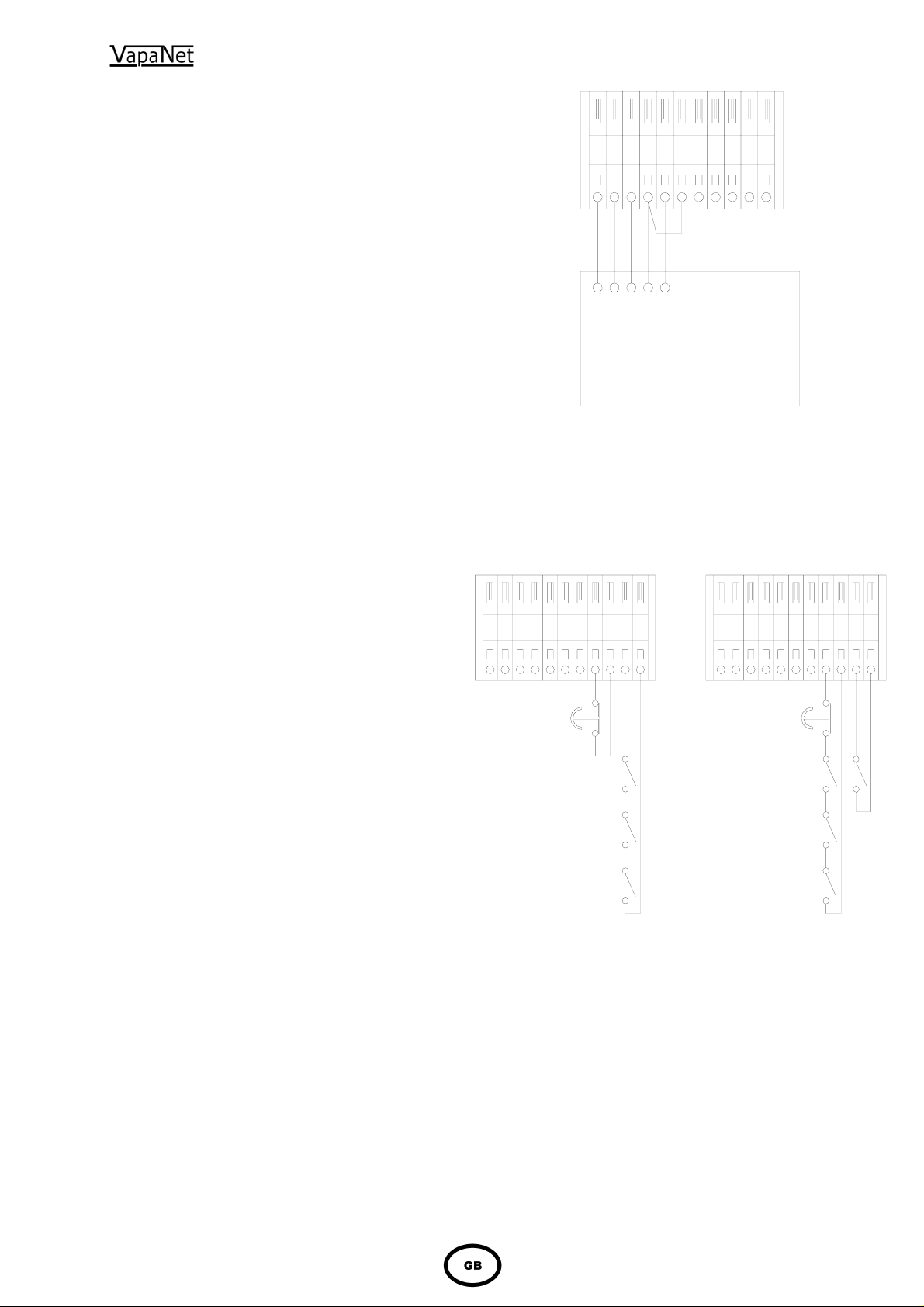
1.5.6 Security Circuit / E.P.O. Shutdown
As standard units are shipped such that terminals 9 &
10 are provided for connection of an E.P.O.
(Emergency Power Off) switch or fire shutdown
facility. Other control interlocks, such as high limit
humidistat, airflow switch and/or fan interlock and time
switches etc. should be connected to terminals 11 &
12. Please note that if a display is connected to
the unit “DI1 Control Option” must be set to
“Shutdown”.
NB breaking terminals 9 & 10 will prevent any unit
operation including frost protection.
1.5.7 Load Shed Option
This can only be evoked via a display, either “hard
wired” or hand held. When this option is selected,
making the connection between terminals 11 & 12 will
activate the “load shed” software routine, which will
inhibit the operation of either the unit or in the case of
twin cylinder units unit or just the 2
limit the power used during peak supply periods. If
this option is selected, the fan interlock, airflow switch
and/or high limit hygrostat should be wired into
terminals 9 & 10 with the EPO switch if fitted (as per
the drawing on the far right). It should be noted that
selection of this option will mean that frost protection
cannot be utilized.
Please note that if a display is connected to the
unit “DI1 Control Option” must be set to the
following:
Single cylinder units: “Load shed”.
Twin cylinder units: either “Load Shed Cyl 2” or
“Load Shed Both”.
nd
cylinder. This will
14
1245678
Thermistor
Thermistor
+9 Volt
0 Volt Ref.
RH Output
Vapac’s accessory kit part numbers for sensors are
Remote Room mounted sensing head FVKIT-107
And
Remote Duct mounted sensing head FVKIT-108
Standard Operation Load Shed Operation
678
9
121011
5
4
2
1
E.P.O.
Fire Stop
Fan
Interlock
Air Flow
Switch
High Limit
Hygrostat
9
101112
Vapac
HUMIDITY
SENSOR
9 VOLT
POWER SUPPLY
TEMPERATURE
AND
HUMIDITY
SENSOR
124
5
E.P.O.
Fire Stop
Fan
Interlock
Air Flow
Switch
High Limit
Hygrostat
8
7
6
9
111012
Load Shed
NB. The total cable length of the network (using the cable recommended by V.H.C.L. – Our part number 8040251) is 500 m and it should
be assumed that there is 1 m of cable in each unit of the “system” (including the “master”).
 Loading...