

Page 1

Vanu Anywave® Base Station Subsystem
Operator Guide
Vanu, Inc. One Cambridge Center, Cambridge MA 02142 t 617.864.1711 www.vanu.com
Copyright © 2007 Vanu, Inc.
Page 2

Page 3

Copyright © 2007 Vanu, Inc. All rights reserved.
The product described in this manual is covered by US patents US 6,584,146 B2, US 6,654,428 B1, US 6,876,864, US
6,889,354, US 7,139,967, and pending patents in the United States and other countries.
Vanu, Inc., the VANU logo, Anywave, and “Where Software Meets the Spectrum” are trademarks or registered trademarks
of Vanu, Inc. in the United States and other countries. The product described in this manual includes copyrighted software.
This software is commercial software.
“Brandywine,” “Intel,” “Powerwave,” “Protium,” and any other trademarked terms used in this manual are trademarks or
registered trademarks of their respective owners.
The terms of use of this software are set forth in detail in a related software license agreement. Except as otherwise set forth
in such software license agreement, none of such copyrighted material may be modified, copied, distributed, performed,
displayed, or reverse engineered.
Vanu, Inc. One Cambridge Center, Cambridge MA 02142 t 617.864.1711 www.vanu.com
Copyright © 2007 Vanu, Inc.
Page 4

Page 5

Anywave BSS Operator Guide
Vanu Anywave Base Station Subsystem Operator Guide
Contents
CHAPTER 1. Introducing the Vanu Anywave BSS ............................................................ 2
Introduction ............................................................................................................................................................ 2
Manual Scope and Objectives............................................................................................................................... 2
What makes Vanu Anywave BSS different? ......................................................................................................... 3
System Operator Role ........................................................................................................................................... 5
CHAPTER 2. BTS Components & Connections.............................................................. 6
Overview................................................................................................................................................................ 6
BTS Server ............................................................................................................................................................ 7
BTS Server, Front View..................................................................................................................................... 7
BTS Server, Front Panel Control Switches and LEDs ...................................................................................... 8
BTS Server, Back View ..................................................................................................................................... 9
RF Front End ....................................................................................................................................................... 10
Protium RF Front End Unit .............................................................................................................................. 10
Overview of Protium RF Front End Connections ............................................................................................ 11
Protium Duplexer Connections........................................................................................................................ 11
Protium Up/Down Converter Connections....................................................................................................... 12
Protium Front-End LEDs.................................................................................................................................. 14
Power Shelf ......................................................................................................................................................... 15
Power Amplifier.................................................................................................................................................... 16
Power Amplifier, Front View ............................................................................................................................ 16
Power Amplifier, Back View............................................................................................................................. 17
Power Amplifier, Back View............................................................................................................................. 18
GPS Timing Source ............................................................................................................................................. 19
GPS 4 Timing Source Connections................................................................................................................. 19
GPS 4 Timing Source Indicator LEDs ............................................................................................................. 20
CHAPTER 3. Base Station Operation ............................................................................ 21
Hardware ............................................................................................................................................................. 21
Appendix A: Acronym Glossary........................................................................................... 22
Index ....................................................................................................................................... 23
i
Page 6

Anywave BSS Operator Guide
Figures
Figure 1: Hardware Architecture............................................................................................................................ 4
Figure 2: BTS Server Front View............................................................................................................................ 7
Figure 3: Server Control Switches and Status LEDs........................................................................................... 8
Figure 4: BTS Server, Back View ........................................................................................................................... 9
Figure 5: Protium Translator System Block Diagram........................................................................................ 10
Figure 6: Protium Duplexer Connections............................................................................................................ 11
Figure 7: Protium RF Up/Down Converter Connections ................................................................................... 12
Figure 8: Protium Front End LEDs....................................................................................................................... 14
Figure 9: Powerwave Power Shelf ....................................................................................................................... 15
Figure 10: Powerwave Amplifier, Front View...................................................................................................... 16
Figure 11: Powerwave Amplifier, Rear View....................................................................................................... 17
Figure 12: GPS 4 Timing Source Connections................................................................................................... 19
Figure 13: GPS 4 Timing Source Indicator LEDs ............................................................................................... 20
Figure 14: Intel Server Power Button .................................................................................................................. 21
ii
Page 7

Anywave BSS Operator Guide
Preface
The Anywave® Base Station Subsystem (BSS) Operator Guide is intended for system users who have completed the Vanu
Anywave System Training Course. This Anywave BSS Operator Guide provides an overview of the Vanu Anywave Base
Station Subsystem application structure, along with information on how to perform system tasks, general system
maintenance, and basic issue resolution procedures.
The Anywave BSS Operator Guide provides information on the following areas:
• Introducing Vanu Anywave Base Station Subsystem
• BTS Overview
1
Page 8

CHAPTER 1. Introducing the Vanu Anywave BSS
Introduction
Welcome to the Vanu Anywave Base Station Subsystem Operator Guide. This manual is designed to serve as a knowledge
resource for the Vanu system currently installed at your site, and to assist you in your role as System Operator. This guide
focuses on ongoing system maintenance, and prepares you to provide first line technical support for your Anywave BSS.
The following is a high level overview of the scope and objectives of this guide:
Manual Scope and Objectives
This manual will cover BTS Hardware Components and Connections
2
Page 9

Anywave BSS Operator Guide
What makes Vanu Anywave BSS different?
The Vanu Anywave GSM BSS provides radio access network functionality by implementing the BTS (Base Transceiver
Station) in software running on a general-purpose server. Signal processing, protocol processing, and all other radio access
network functionality are implemented as application level software running on top of a Debian GNU/Linux system.
The Anywave BTS system uses Protium wideband RF front ends from Protium Technologies.
The Vanu Anywave BSS is composed of three major subsystems:
• RF front end, supporting the 850 MHz band, and providing Analog-to-Digital and Digital-to-Analog conversion
• Signal Processing
• Back end network connectivity
Vanu, Inc. integrates these subsystems, running its software on top of the COTS hardware that comprises a complete radio
access network, including the traditional functionality of the BTS.
3
Page 10
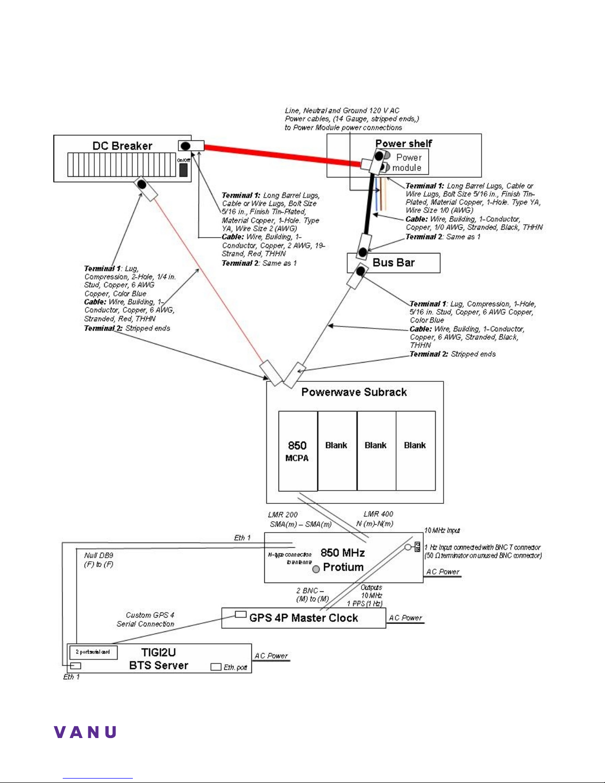
4
Figure 1: Hardware Architecture
Page 11

Anywave BSS Operator Guide
System Operator Role
As System Operator, you will maintain and support all components of the Vanu Anywave wireless infrastructure. By the time
you receive this document, you will already have met several important milestones. You will have worked with Vanu, Inc.’s
Deployment group to plan and deploy your current installation, and you will have attended the Vanu, Inc. System Operator
Training Course. Both of these milestones will lay the foundation on which to build your knowledge base for Vanu, Inc.
products and prepare you to service your system.
The following is an overview of the System Operator role and some of the duties you will be expected to perform:
• Manage technical issues regarding hardware and software required to run the Vanu Anywave network.
• Diagnose radio access network problems and proactively monitor network performance.
• Introduce and train other users who will support the system.
5
Page 12

CHAPTER 2. BTS Components & Connections
The BTS provides the air interface in a particular region, also known as a cell, to each Mobile Station (cell phone) located
within its border with an active connection.
In this section, we will review the following list of BTS Hardware components:
• BTS Server
• RF Front Ends
• Power Amplifier
• Power Shelf
• GPS Timing Source
Overview
The Vanu Anywave BTS implements all of the signal processing required for full GSM base station functionality in software
running on a server. A standard system implements the components of the GSM Phase II specification for voice
communications. It supports mobile phones using full-rate (GSM 6.10) vocoders. For the purpose of your deployment, each
Vanu BTS is complemented by a Protium RF Front End.
6
Page 13
Anywave BSS Operator Guide
BTS Server
The Anywave BTS software application is hosted on an Intel TIGI2U NEBS server running a Debian GNU/Linux operating
system. The RF data enters the server from the Protium RF front end units through an Ethernet connection. GSM audio
signaling is routed internally from mobile to mobile using the Anywave Micro-MSC. An Ethernet port connects the BTS
server to the Ethernet switch. Connections from an Ethernet port in the BTS server are used to connect it to the Protium RF
Front End units.
The Intel TIGI2U server is a Network Equipment Building Standards Level 3 and ETSI certified server. The TIGI2U server
has redundant power supplies, fans, and hard drives to ensure that the BTS remains functional in the event of hardware
failure.
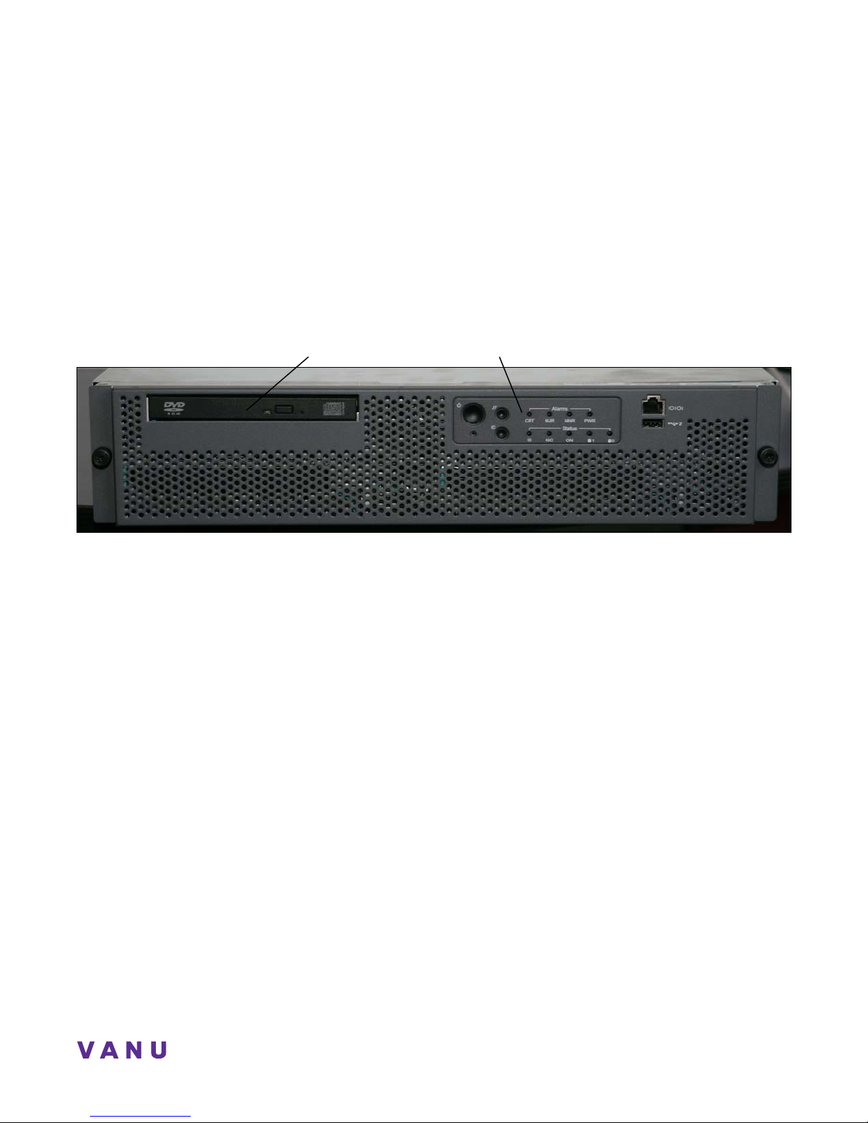
BTS Server, Front View
Peripheral Bay
Figure 2: BTS Server Front View
Control Switches and Status LEDs
7
Page 14
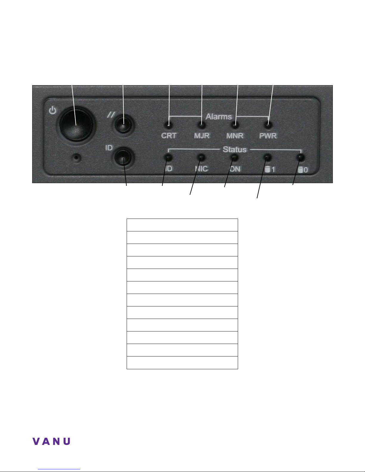
BTS Server, Front Panel Control Switches and LEDs
Power Button Reset Switch
ID Switch
Critical Alarm
System ID LED
Major Alarm
NIC0/NIC1 LED
Minor Alarm
Main Power LED
Disk 2 Status LED
Power Alarm
Disk 1 Status LED
Figure 3: Server Control Switches and Status LEDs
Power Button
Reset Switch
Critical Alarm LED
Major Alarm LED
Minor Alarm LED
Power Alarm LED
ID Switch
System ID LED (white)
NIC0/NIC1 Activity LED (green)
Main Power LED
Disk 2 Activity/Fault LED (green/amber)
Disk 1 Activity/Fault LED (green/amber)
8
Page 15
Anywave BSS Operator Guide
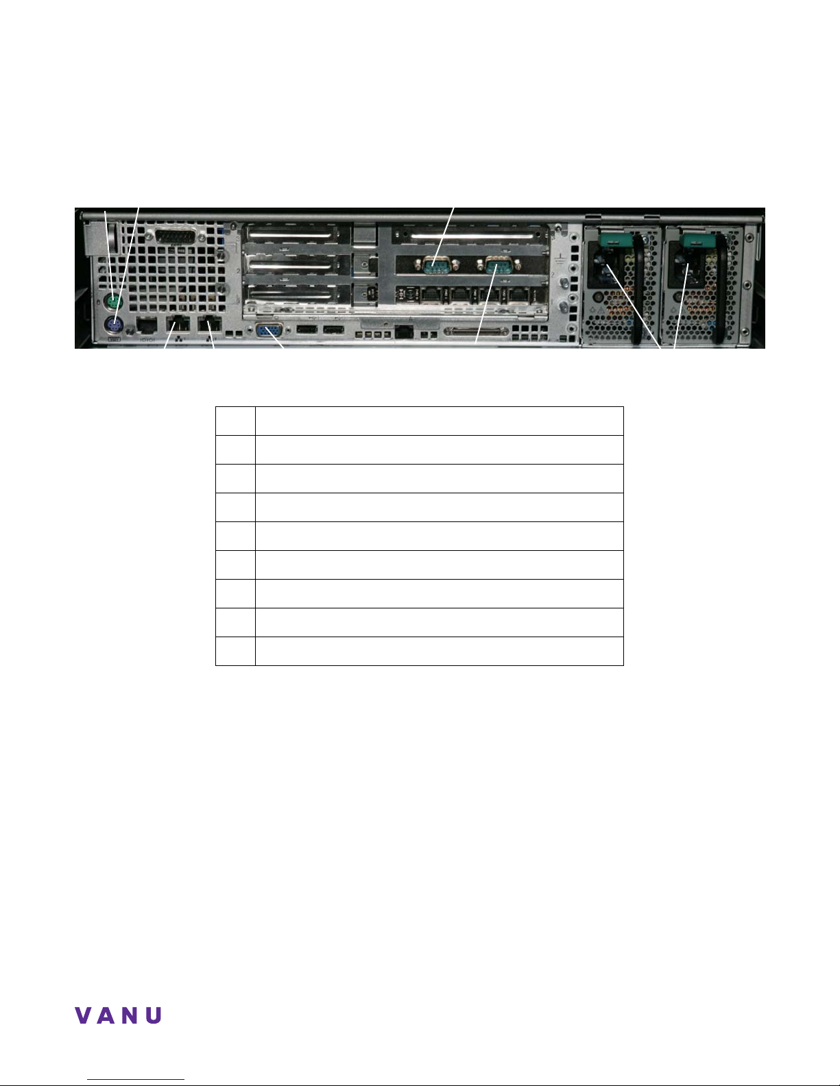
BTS Server, Back View
Mouse & keyboard connections
Serial Connection to Protium
NIC 1
NIC 2
Monitor connection
Serial Connection to GPS
Figure 4: BTS Server, Back View
Qty Connection
1 Mouse connection
1 Keyboard connection
1 NIC 1 Ethernet connection
1 NIC 2 Ethernet connection
1 Serial connection to Protium RF Front End
1 Serial connection to GPS Timing Source
1 Monitor connection
2 Power jack connections to 120 V power source
Power Cables
9
Page 16
RF Front End
The wideband RF front ends perform transmission and reception over the air interface between the BTS and a number of
GSM mobiles. Using a wideband multi-channel front end allows one BTS unit to transmit and receive multiple carriers over a
wide frequency band of up to 25 MHz.
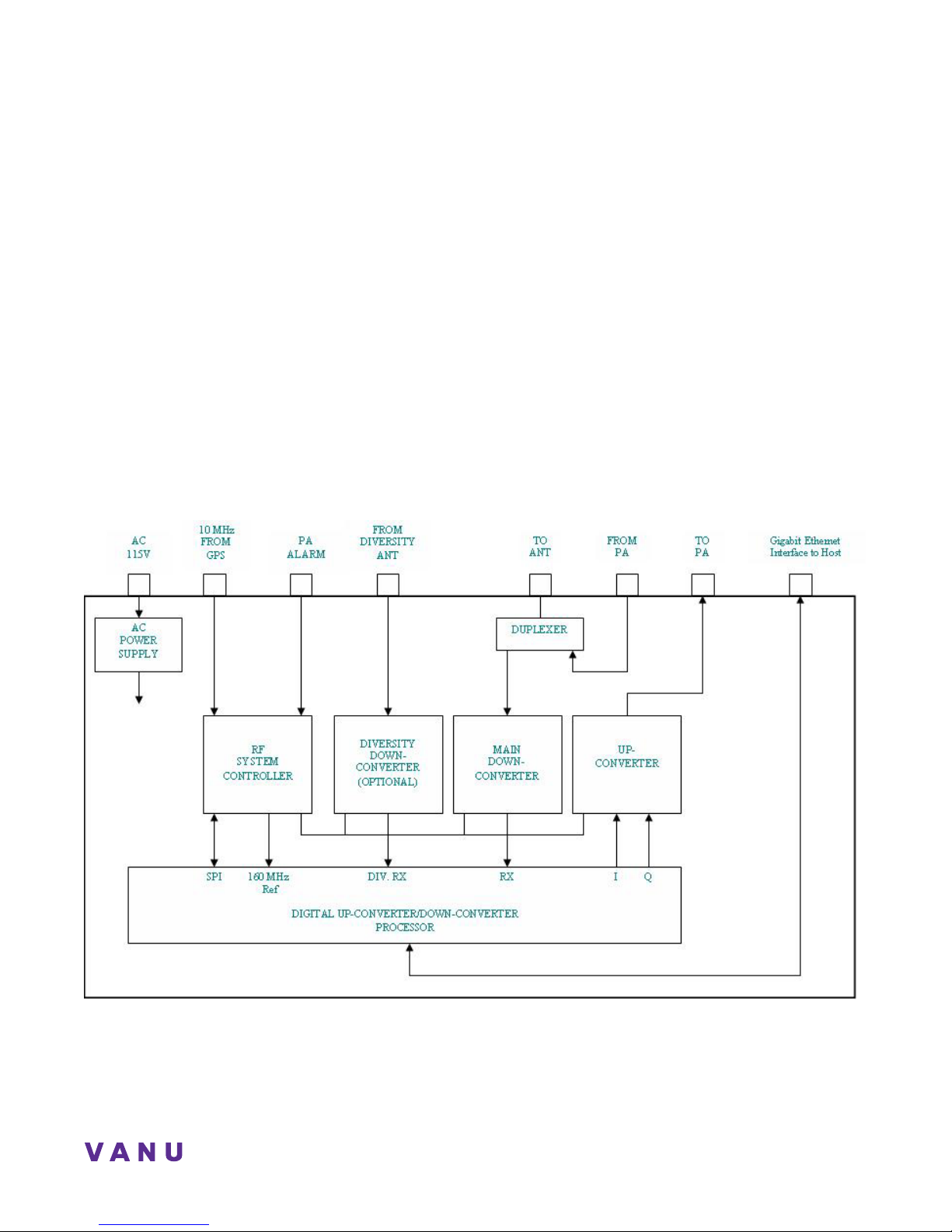
The RF front ends include both the RF up/down converters and the digital IF subsystem, which perform digital filtering,
timestamp injection and other functions. The BTS software communicates with the RF front ends using digital baseband
samples.
Protium RF Front End Unit
Your deployment includes four Protium RF Front Ends, all of which have a Duplexer, an Up/Down converter, and also do
channelization and resampling. The Protium RF Front End Units are divided into two compartments for noise containment.
The lower compartment contains the Duplexer and associated filters. The upper compartment contains the RF Up/Down
converters, analog-to-digital converters, digital-to-analog converters, and other digital hardware.
The RF signals are piped between the two compartments externally to maintain the noise separation. We will refer to the
lower compartment as the Duplexer and the upper compartment as the Up/Down Converter for simplicity. The units will be
installed and serviced as one box, but for clarity we will describe them here as two components.
Figure 5: Protium Translator System Block Diagram
10
Page 17
Anywave BSS Operator Guide
Overview of Protium RF Front End Connections
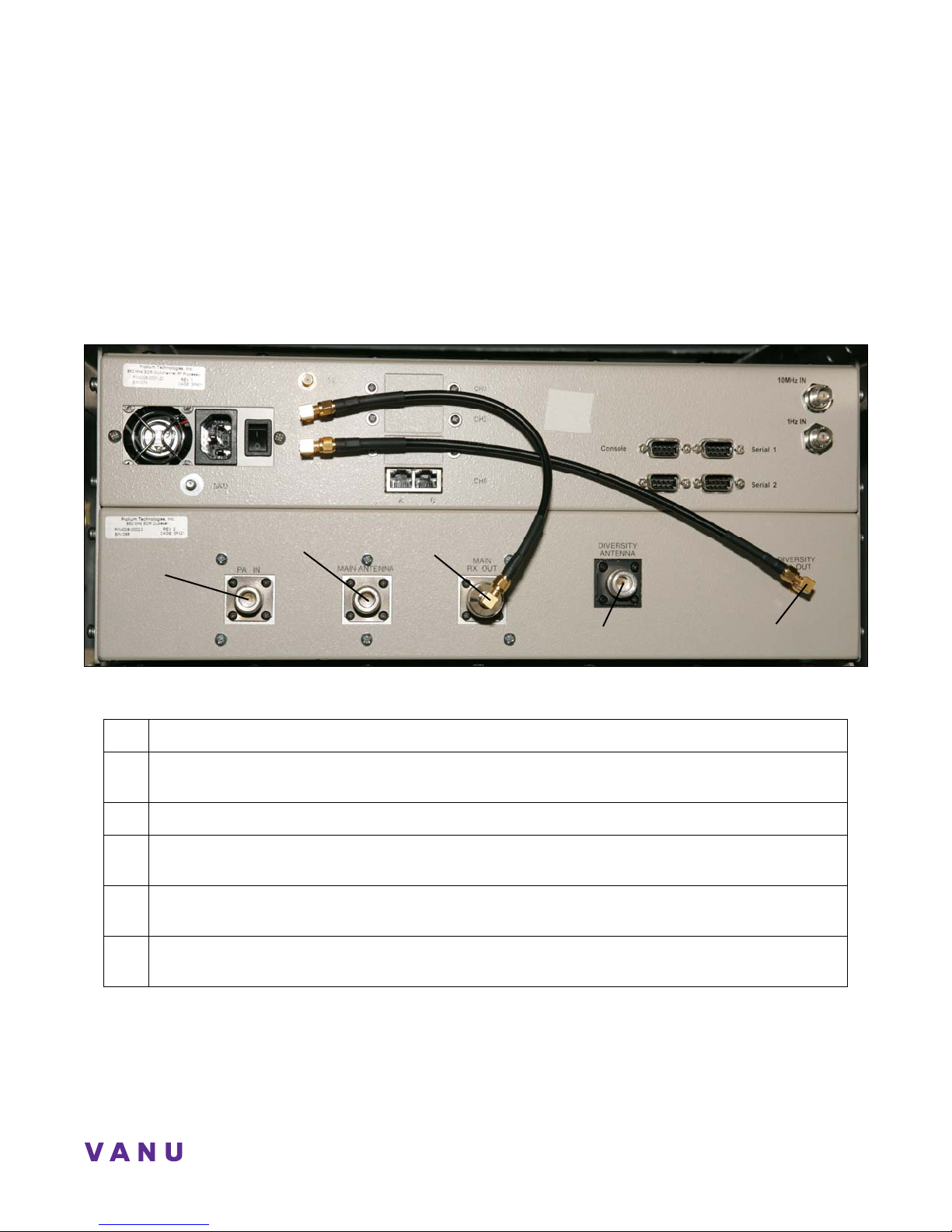
The RF signal is received through the Main Antenna port, located on the Duplexer panel. RF data received from the Main
Antenna is run through the Duplexer, out the Main RX SMA port, then over a cable to the Main RX SMA on the Up/Down
Converter panel. This signal is then converted to digitized data and sent out through an Ethernet port to the server. These
digitized data are then converted to an RF signal and transmitted out the BTS antenna.
This section provides a general overview of the connectors on the RF Front End Up/Down Converters and Duplexers.
Protium Duplexer Connections
Main Antenna
Main RX Out
PA in Port
Diversity Antenna
Diversity RX Port
Figure 6: Protium Duplexer Connections
Qty Connection
PA In port: an N connector linking the Power Amplifier to the duplexer. The amplified RF signal
1
from the PA enters the duplexer at this port.
1 Main Antenna port: an N Connector connecting the Antenna Coax Cable to the duplexer.
Main RX port: an SMA connector connecting to the Upper RX SMA Connect. The RF signal travels
1
from this port to the Protium upper half to be digitized.
Diversity RX port: an SMA connector connecting to the Upper Diversity RX port, routing filtered
1
secondary RX data.
Diversity Antenna port: an N connector connecting the Diversity Coax Cable from the secondary
1
antenna to the secondary RX path filter.
11
Page 18
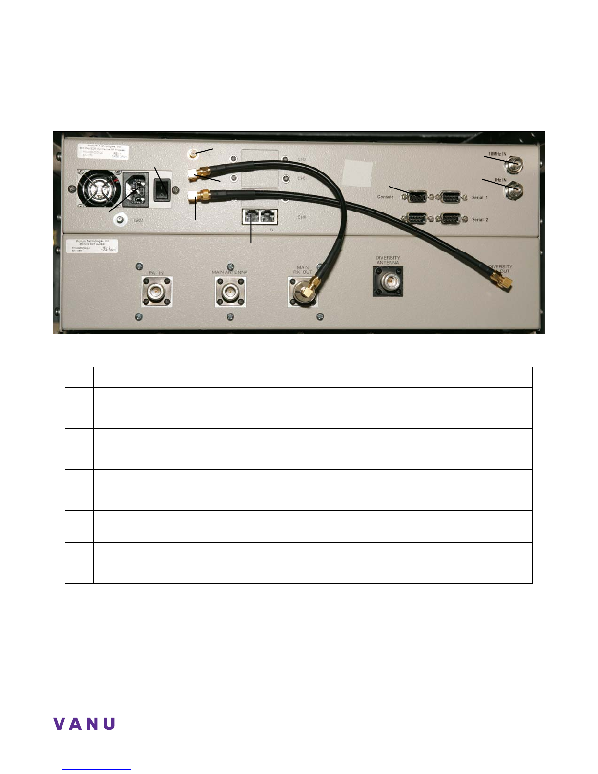
Protium Up/Down Converter Connections
TX Port
Power Switch
RX Port
Power Jack
Diversity RX Port
Ethernet port A
Figure 7: Protium RF Up/Down Converter Connections
Qty Connection
1 Chassis Power Jack: Standard power connection for RF Unit
1 Power Switch: On and Off switch
Console serial port
10 MHz In port
1 Hz In port
1 TX SMA Port: TX connection to PA In port on the PA.
1 RX port: RX connection to Main RX port on duplexer
1 Diversity RX port: Connects to the lower Diversity RX port on the duplexer
4 Ethernet Ports: Data path between Protium and the assigned Ethernet port on the BTS server.
1 Console Port: An RS232 DB-9 port used to monitor system error messages and to configure the
unit from the server. This connection is made between the BTS server and only one RF Front End.
1 10 MHz In port: 10 MHz Reference input from GPS Timing Source
1 1 Hz In port: 1 PPS Reference input from GPS Timing Source
12
Page 19
Anywave BSS Operator Guide
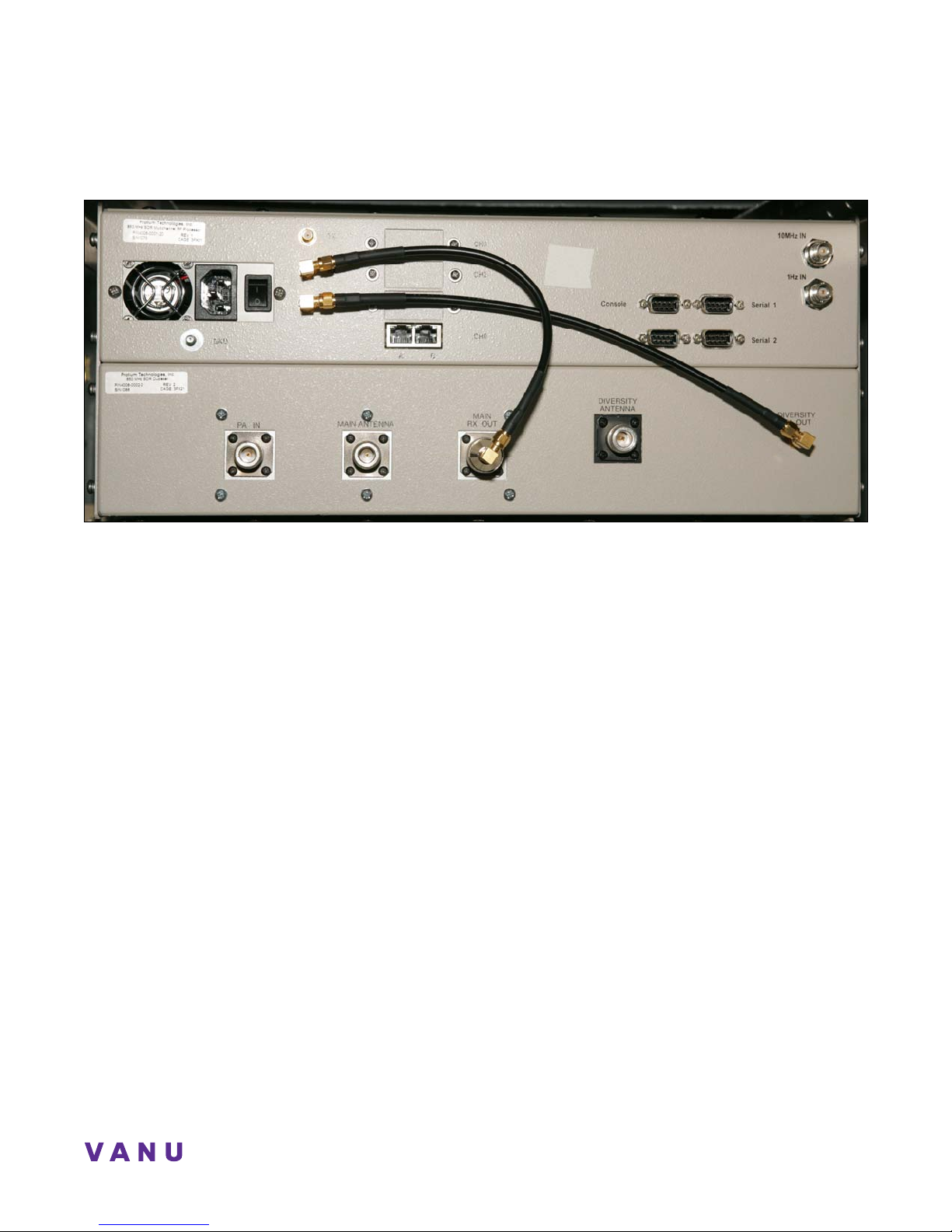
Protium 850 RF Front End
13
Page 20
Protium 850 Indicator LEDs
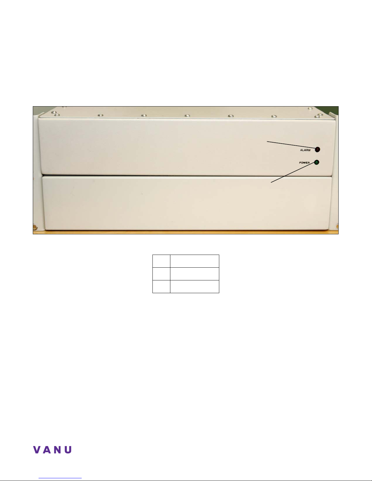
The front of the Protium unit has two LED lights, which serve both compartments of the RF Front End unit. The green LED
indicates that power is active on the unit. The red LED indicates that an alarm in the system has been triggered.
Protium Front-End LEDs
RF Alarm LED
Power LED
Figure 8: Protium Front End LEDs
Qty Connection
1 RF Alarm LED
1 Power LED
14
Page 21
Anywave BSS Operator Guide
Power Shelf
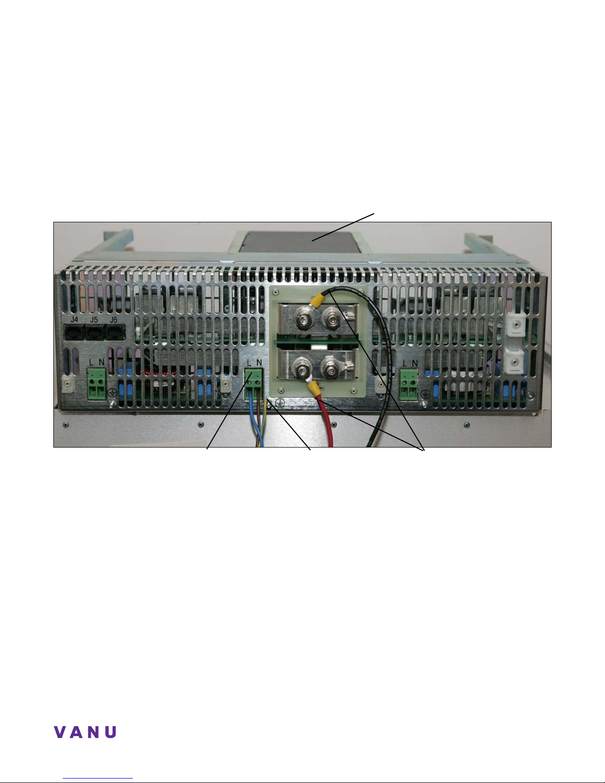
The Powerwave Power Shelf converts 120 V AC current to 28 v DC current. The capacity to hold up to three power modules
makes it easy to swap out an existing power module if necessary, or to increase DC power. The Power Shelf used in your
deployment will have two power modules, with a total of 8 connections (4 red, 4 black) to the Powerwave MCPA. Each
power modules will have its own 120 V power source.
Please Note: The power source connections are directly in front of the power module being used.
Power Module
120 V power in: Line and
Ground connection
+ 27 V and Return DC power out
Neutral connections
Figure 9: Powerwave Power Shelf
15
Page 22
p
Power Amplifier
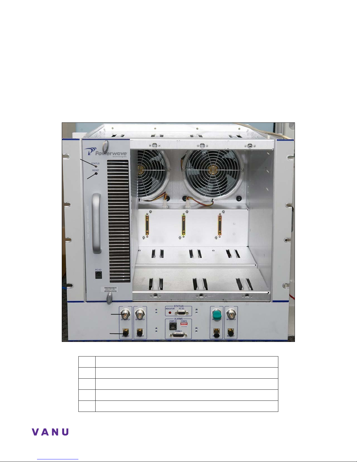
The Powerwave Amplifier is used as the Power Amplifier for each RF Front End in the network. The output from the RF
Front End is sent to the PA via a Coax cable and is then amplified by 63 dB.
You will have four Power Amplifiers in your deployment. Only the two PAs in use should be powered on. The two PAs not
in use should be shut off using the On/Off Reset Switch located on the front of each PA.
Power Amplifier, Front View
Status LED
On/Off Reset
Switch
PA-1
PA-1 PA-2
RF Output
RF In
ut
Figure 10: Powerwave Amplifier, Front View
Qty Connection
1 Status LED
1 Reset Switch
4 RF Output Connections to the RF Front End PA In port for slots 0-3
4 RF Input Connections from the RF Front End Tx port for slots 0-3
16
PA-2 PA-3
PA-3
PA-4
PA-4
Page 23
Anywave BSS Operator Guide
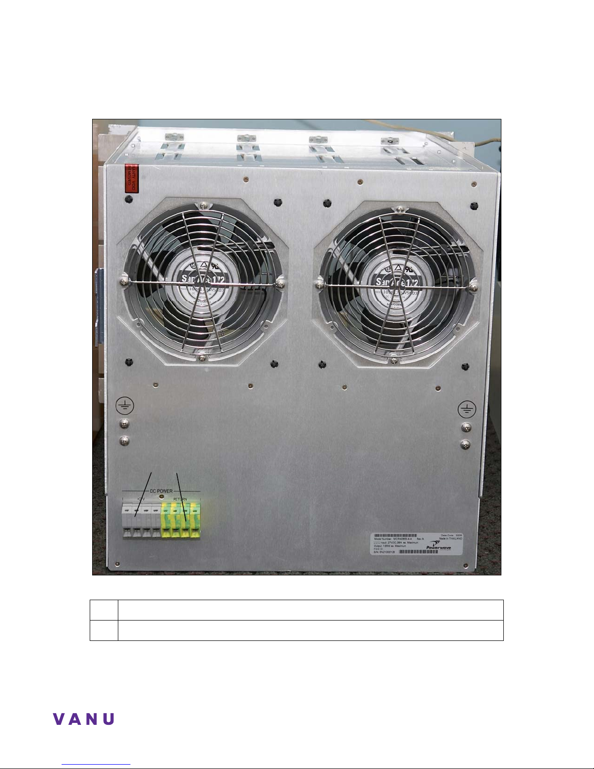
Power Amplifier, Back View
Rear Power Terminal Blocks
Figure 11: Powerwave Amplifier, Rear View
Qty Connection
4 Power Terminal block for slots 0-3. (See “Note” about power connections on page 15.)
17
Page 24
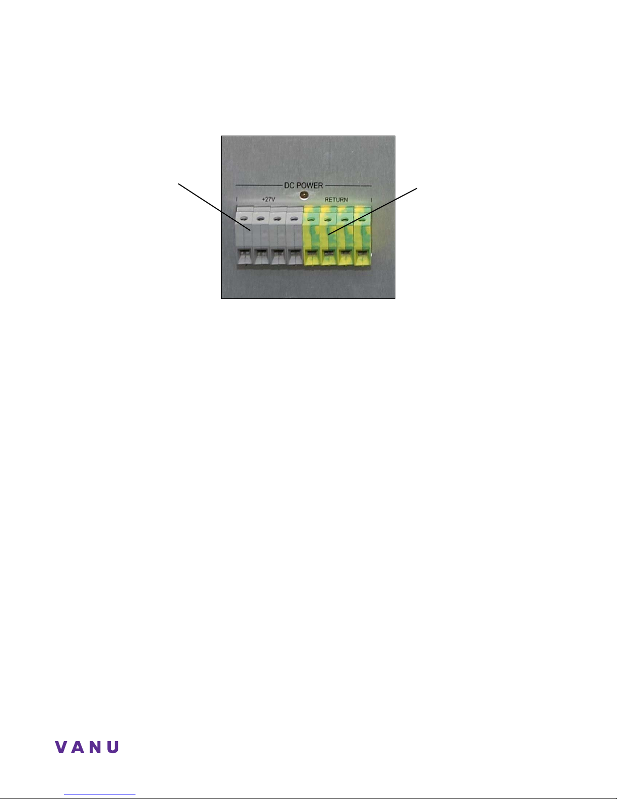
3:
Power Amplifier, Back View
“+ 27 V” Power Block
4:
“Return” Power Block
3 2 1 0
3 2 1 0
18
Page 25
Anywave BSS Operator Guide
p
p
GPS Timing Source
The Brandywine GPS 4 Timing Source simply provides a 10 MHz and 1 Hz clock signal to the Protium for precision timing.
The Timing Source provides a reference clock to the RF equipment for timestamping. Timestamps are used to ensure the
correct alignment of data throughout the system. The serial port connection from the GPS Timing Source to the BTS server is
used for configuration and diagnostic purposes.
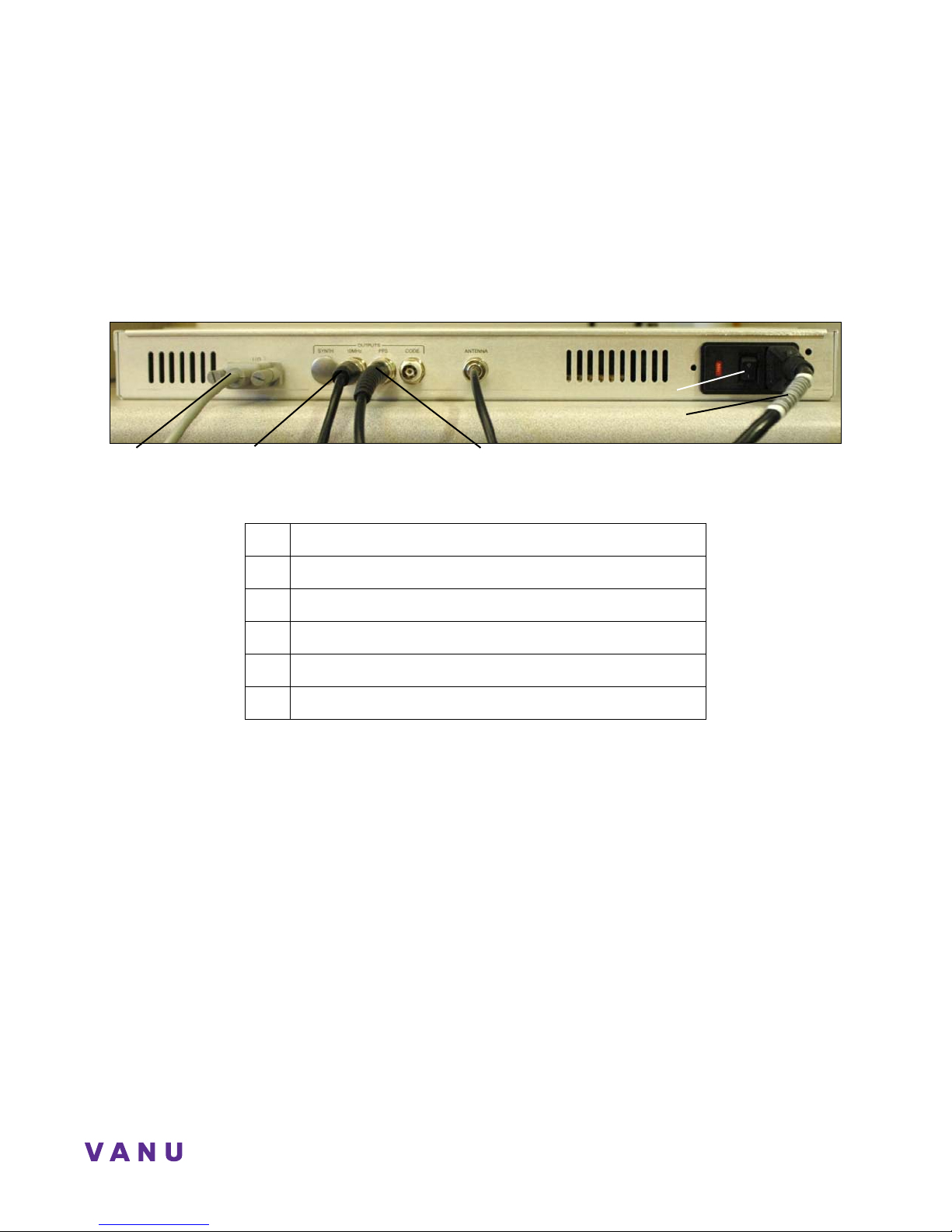
GPS 4 Timing Source Connections
Power Switch
I/O Serial Port
Connection to Server
Coax Cable from 10 MHz Port
to 10 MHz
ort on RF Front End
Figure 12: GPS 4 Timing Source Connections
Qty Connection
1 Cable from serial port to server
1 Coax cable from the 10 MHz port to Protium 10MHz Port
1 Coax cable from the 1 PPS port to Protium 1 Hz Port
1 Coax cable to the external antenna
1 Power cable
Coax Cable from 1 PPS Port
to 1Hz
ort on RF Front End
Power Cable
19
Page 26
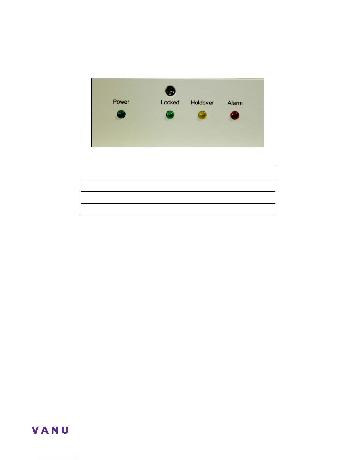
GPS 4 Timing Source Indicator LEDs
Figure 13: GPS 4 Timing Source Indicator LEDs
Power: Indicates that the unit is powered on.
Locked: The Protium unit is synched with the GPS.
Holdover: There is a valid clock, but it is not synchronized with the GPS.
Alarm: The GPS unit is not functioning properly.
Please Note: The “Power” LED should be lit when the unit is powered on.
20
Page 27

Anywave BSS Operator Guide
CHAPTER 3. Base Station Operation
Hardware
Once all the hardware is connected, the system can be launched. Turn on the power for each of the hardware components.
The power buttons or switches are located on the front of the TIGI2U server, below, and on the back of the Protium (see
Figure 7, page 12) and GPS timing source unit (see Figure 12, page 19).
Power Button
Figure 14: Intel Server Power Button
Base Station Set Up
Once the system is powered on, the base station will be functional within minutes. The BTS application will start
automatically.
21
Page 28

Appendix A: Acronym Glossary
ARFCN Absolute Radio Frequency Control Number
BSC Base Station Controller
BSS Base Station Subsystem
BTS Base Station Transceiver Subsystem
GPS Global Positioning System
HLR Home Location Register
iLO
Integrated Lights Out
HP remote management system
MSC Mobile Station Controller
PA Power Amplifier
PCI Peripheral Component Interconnect
PPS Port Pulse Per Second port
RF Radio Frequency
RH Radio Head
SDR Software Defined Radio
SMS Short Messaging Service
TRAU Transcoder and Rate Adaptor Unit
VoIP Voice over Internet Protocol
VPN Virtual Private Network
WAP Wireless Application Protocol
WIC Wide Area Network Interface Cards
22
Page 29

Anywave BSS Operator Guide
Index
A
Acronym Glossary · 22
Air interface · 10
Analog-to-Digital
converters · 10
Antenna
Main · 11
B
Back end connectivity · 3
Base Transceiver Station · See BTS
BTS · 6, 10
server · 6, 7
D
Digital-to-Analog converters · 10
Duplexer · 10
E
Ethernet · 11
L
Linux · 3, 7
M
Manual
Objectives · 2
Scope · 2
Mobile Station · 10, See Mobile phone
Mobile Station Controller · See MSC
P
Power Amplifier · 6
Power Converter · 6, 15
Protium · 10
back view · 11, 12
connections · 14
duplexer connections · 11
front end unit · 10
front end view · 14
RF connections · 12
signal lights · 14
Protocol processing · 3
G
GPS
indicator LEDs · 20
timing source connections · 19
GPS Master Clock · 6
GSM · 3
base station · 6
Phase II · 6
signals · 10
H
Hardware
running · 21
I
Intel Server · 7
23
R
Reference Clock · See Timing Source
RF
Front End · 16
RF Front End · 6, 10
LEDs · 14
RF up/down converters · 10
RX · 11
S
Signal processing · 3
SMR Amplifier · 16
Subsystems · 3
System Operator Role · 5
Page 30

T
Timestamping · 19
Timing Source · 19
Transcoder and Rate Adaptor Unit · See TRAU
U
Up/Down Converter · 10
V
Vocoders · 6
24
 Loading...