

Page 1

All Rights Reserved
VT-HMI 5071
User’s Manual
Vantron Technology
www.vantrontech.com
Page 2

VT-HMI-5071
Revision History:
No.
Version
Description
Date
1
V1.0
First release
Apr. 25, 2008
2
V1.1
Update Ordering Information
Sept. 17, 2008
3
V1.2
Add VESA Information
Jan. 25, 2010
Page 3

Table of Contents
1 Foreword........................................................................................................1
1.1 Copyright Notice ...............................................................................1
1.2 Notes ...................................................................................................2
1.3 Statement ...........................................................................................2
1.4 Disclaimer...........................................................................................3
1.5 Limitation of Liability/Non-warranty .............................................3
1.6 Safety Instructions ............................................................................3
1.7 Precautions ........................................................................................4
1.8 Safety Instructions for Power Cables and Accessories ...............5
2 Overview........................................................................................................7
2.1 Introduction .......................................................................................7
2.2 Product Series....................................................................................8
2.2.1 Product Order Coding Rule .............................................8
2.2.2 Ordering Information .......................................................9
3 VT-HMI-5071 Hardware Instructions .................................................... 10
3.1 Product Appearance ...................................................................... 10
3.2 Specifications .................................................................................. 11
3.3 Interface Instructions .................................................................... 13
3.3.1 Bottom View ................................................................... 13
3.3.2 Left View.......................................................................... 14
3.4 Dimension ....................................................................................... 15
3.5 Hardware Installation .................................................................... 16
3.6 Interface Description ..................................................................... 17
3.6.1 DC24V Power Input ....................................................... 17
Page 4

3.6.2 Ethernet Interface ......................................................... 18
3.6.3 D Sub-9 RS232 Connector ............................................ 19
3.6.4 USB Host Conn ector ...................................................... 20
3.6.5 CAN Connector ............................................................... 20
3.7 I/O Interface Instructions ............................................................. 21
3.7.1 RS485/422....................................................................... 21
3.8 Packing List ...................................................................................... 23
4 Software Instructions............................................................................... 24
4.1 Brief Introduction........................................................................... 24
4.1.1 Serial Port Instructions ................................................. 24
4.2 WinCE Instructions ........................................................................ 25
4.2.1 Windows CE Application Development ..................... 25
4.2.2 Windows CE Firmware Update.................................... 25
4.2.3 Instructions for Windows CE Configuration Files..... 27
4.2.4 Notice of Touch Screen in WinCE................................ 29
4.3 Linux Instructions ........................................................................... 31
4.3.1 Linux Application Development .................................. 31
4.3.2 Linux Image Programming ........................................... 32
4.3.3 Instructions for Linux Configuration Files.................. 34
4.3.4 start.txt ............................................................................ 35
4.3.5 tty_config.txt .................................................................. 35
4.3.6 hw_config.txt.................................................................. 35
4.3.7 root_config.txt................................................................ 36
4.3.8 Notice of Touch Screen in Linux .................................. 37
5 Tips ............................................................................................................... 38
Page 5

VT-HMI-5071
1
1 Foreword
1.1 Copyright Notice
While all information contained herein have been carefully checked
to assure its accuracy in technical details and printing, Vantron
assumes no r esponsibility resulting from any error or features of this
manual, or from improper uses of this manual or the software. Please
contact our technical department for relevant operation solutions if
there is any problem that cannot be solved according to this manual.
Vantron r eserves all rights of this manual, including the right to
change the content, form, product features, and specifications
contained h erein at any time without pri or notice. The latest v ersion
of this manual is at www.vantrontech .co m.cn. Please contact Vantron
for further information:
Page 6

VT-HMI-5071
2
The trademarks and registered trademarks in this manual are
properties of their respective owners. No part of this manual may be
copied, reproduced, translated or sold. No changes or other purposes
are permitted without the prior written consent of Vantron.
Vantron res erves the right of all publicly-released copies of this
manual.
1.2 Notes
Applicable notes are listed in the following table:
Sign
Notice Type
Description
Notice
Important information and r egulations
Caution
Caution for latent da mage to system or harm
to personnel
1.3 Statement
It is recommended to read and comply with this manual before
operating VT-HMI which provides important guidance and h elps
decreasing the danger of injury, electric shock, fire, or any damage to
the device.
Page 7

VT-HMI-5071
3
1.4 Disclaimer
Vantron assumes no legal liability of accidents resulting from failure
of confor ming to the safety instructions.
1.5 Limitation of Liability/Non-warranty
For direct or indirect damage to this device or other devices of
Vantron caused by failure of conforming to this manual or the safety
instructions on device label, Van tron assumes neither warranty nor
legal liability even if the device is still under warranty.
1.6 Safety Instructions
Keep and comply with all operation instructions, warnings, and
information.
Pay attention to warnings on this device.
Read the following precautions so as to decrease the dan ger of
injury, electric shock, fire, or any da mage to the device.
Page 8

VT-HMI-5071
4
1.7 Precautions
Pay attention to the product labels/safety instructions printed on
silk screens.
Do not try repairing this product unless declared in this manual.
Keep away from heat source, such as heater, heat dissipater, or
engin e casing.
Do not insert other items into the slot (if any) of this device.
• Keep the ventilation slot ventilated for cooling.
•System fault may arise if other items are inserted into this device.
Installation: ensure correct installation according to instructions
from the manufacturer with recommended installation tools.
Ensure ventilation and smoothn ess according to relevant
ventilation standard.
Page 9

VT-HMI-5071
5
1.8 Safety Instructions for Power Cables and Acce ssories
Proper power source only
Start only with power source that satisfies voltage label and the
voltage n ecessary according to this manual. Please contact technical
support personnel of Vantron for any unc ertainty about the
requirements of necessary power source.
Use tested power sourc e
This product still contains a button lithium battery as a real -time
clock after its external power source is removed and therefore should
not be short-circuited during transportation or placed under high
temperature.
Place cables properly:
Do not place cables at any place with extrusion danger.
Page 10

VT-HMI-5071
6
Cleaning Instructions
Please power off before cleaning the device.
Do not use spray detergent.
Clean with a damp cloth.
Do no t try cleaning exposed electronic components unless with a
dust collector.
Support for special fault: Power off and con tact technical support
personnel of Vantro n in case of the following faults:
The device is damaged.
The temperature is excessively high.
Fault is still not solved after the operation according to the
manual.
Page 11

VT-HMI-5071
7
2 Overview
2.1 Introduction
Thank you for choosing Vantron. It is our commitment to pro vide
our valued customers with the embedded devices equipped with the
state-of-the-art technology and the b est produc t services.
HMI, the abbreviation for Human-Machine Interfac e, enables the
interaction b etween operators/users and applications, connects
industrial control products such as PLC, transducer, DC speed
regulator, meter, etc. HMI adopts a display for displaying and input
units such as touch screen, keyboard, mouse, etc . for writing working
parameters or inpu tting operation commands. As a digital device for
realizing information interaction between human and machine, HMI is
composed of hard ware and software. Based on its ample function
interfaces and p owerful user operational interface, it is very suitable
for control units such as medical device, intelligent transportation,
industrial field, etc ..
Vantron’s VT-HMI products are based on the most advanced ARM
and Intel Atom processors and have low-power consumption and hi gh
integration. The products are designed for applications such as
industrials, medicals, and transportations etc..
Page 12

VT-HMI-5071
8
2.2 Product Series
2.2.1 Product Order Coding Rule
VT-HMI- A BB C:
Type suffix:
1: Basic type;
2: Enhanced type or other types
Screen size:
07、08、10、15: for LCD in 7、8、10、15 inches.
Product series:
3:PXA270 ARM10 proc essor platform
5:IMX31 ARM11 processor platform
6:Intel ATOM x86 processor platform
Page 13

VT-HMI-5071
9
2.2.2 Ordering Information
Series 3: PXA 270 ARM10 processor based
VT-HMI-3081
8.4” TFT, PXA270 520MHz, Ethernet, RS232,
RS422/485, USBH, USBD
VT-HMI-3082
8.4” TFT, PXA270 520MHz, Ethernet, 5xRS232,
2xRS422, RS485, 4xUSBH, CAN
VT-HMI-3101
10.4” TFT, PX A270 520MHz, Ethernet, RS232,
RS422/485, USBH, USBD
VT-HMI-3102
10.4” TFT, PXA270 520MHz, Ethernet, 5xRS232,
2xRS422, RS485, 4xUSBH, CAN, VGA
Series 5: iMX31 ARM11 processor based
VT-HMI-5071
7” TFT, 16:9 Wide Screen, iMX31 532MHz,
Ethern et, RS232, RS422/485, USBH2 .0
VT-HMI-5101
10.2” TFT, 16 :9 Wid e Scr een, iMX31 532MHz,
Ethern et, RS232, RS422/485, USBH2.0
Series 6: x86 processor based
VT-HMI-6101-1
10.4” TFT, ATOM 1.1GHz, 512MB, 1000 M
Ethern et, RS232, RS422/485, 4xUSBH2.0
VT-HMI-6101-2
10.4” TFT, ATOM 1.6GHz, 512MB, 1000 M
Ethern et, RS232, RS422/485, 4xUSBH2.0
VT-HMI-6151-1
15.1” TFT, ATOM 1.1GHz, 512MB, 1000 M
Ethern et, RS232, RS422/485, 4xUSBH2.0
VT-HMI-6151-2
15.1” TFT, ATOM 1.6GHz, 512MB, 1000 M
Ethern et, RS232, RS422/485, 4xUSBH2.0
Page 14
VT-HMI-5071
10
3 VT-HMI-5071 Hardware Instructions
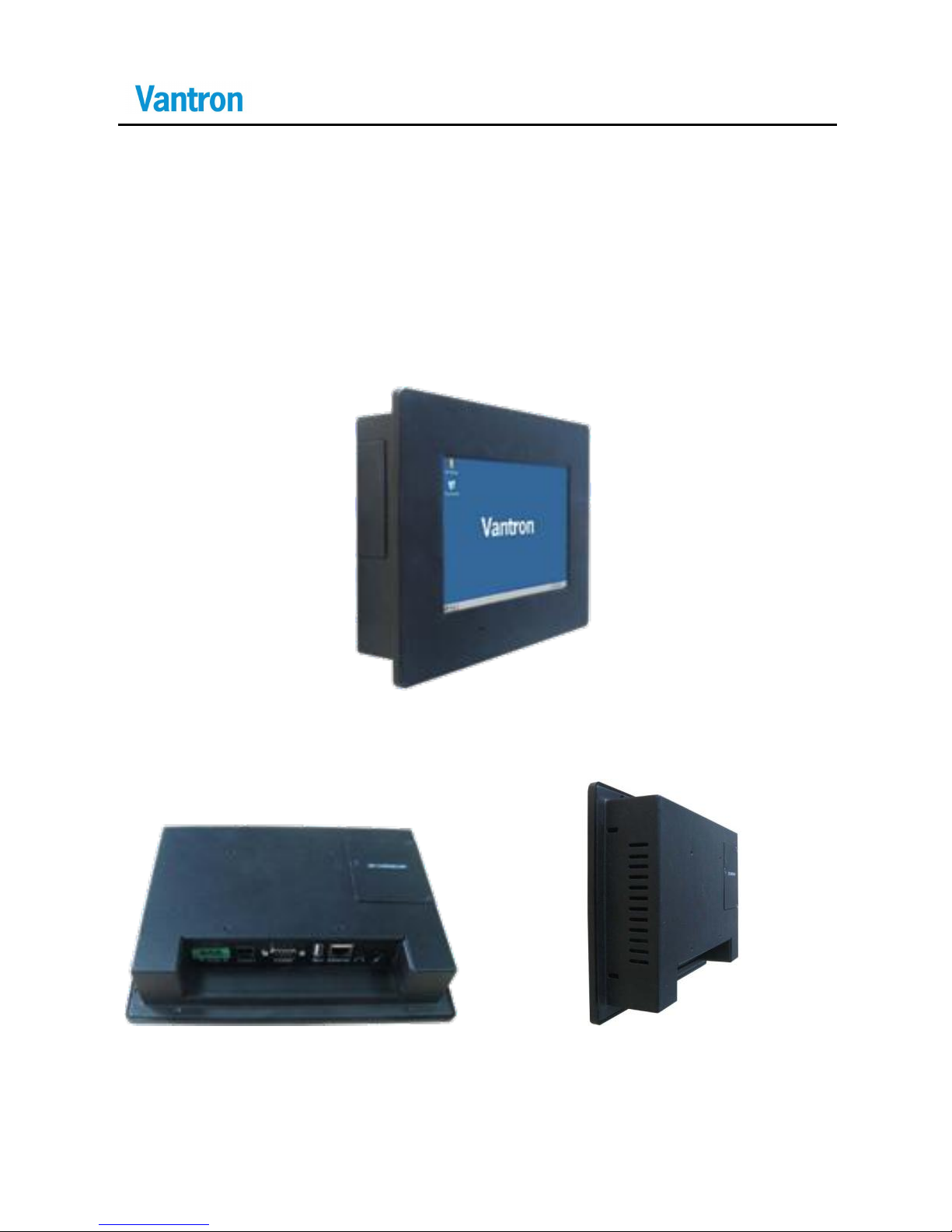
3.1 Product Appearance
Front & Side View
Top View Back & Side View
Page 15
VT-HMI-5071
11
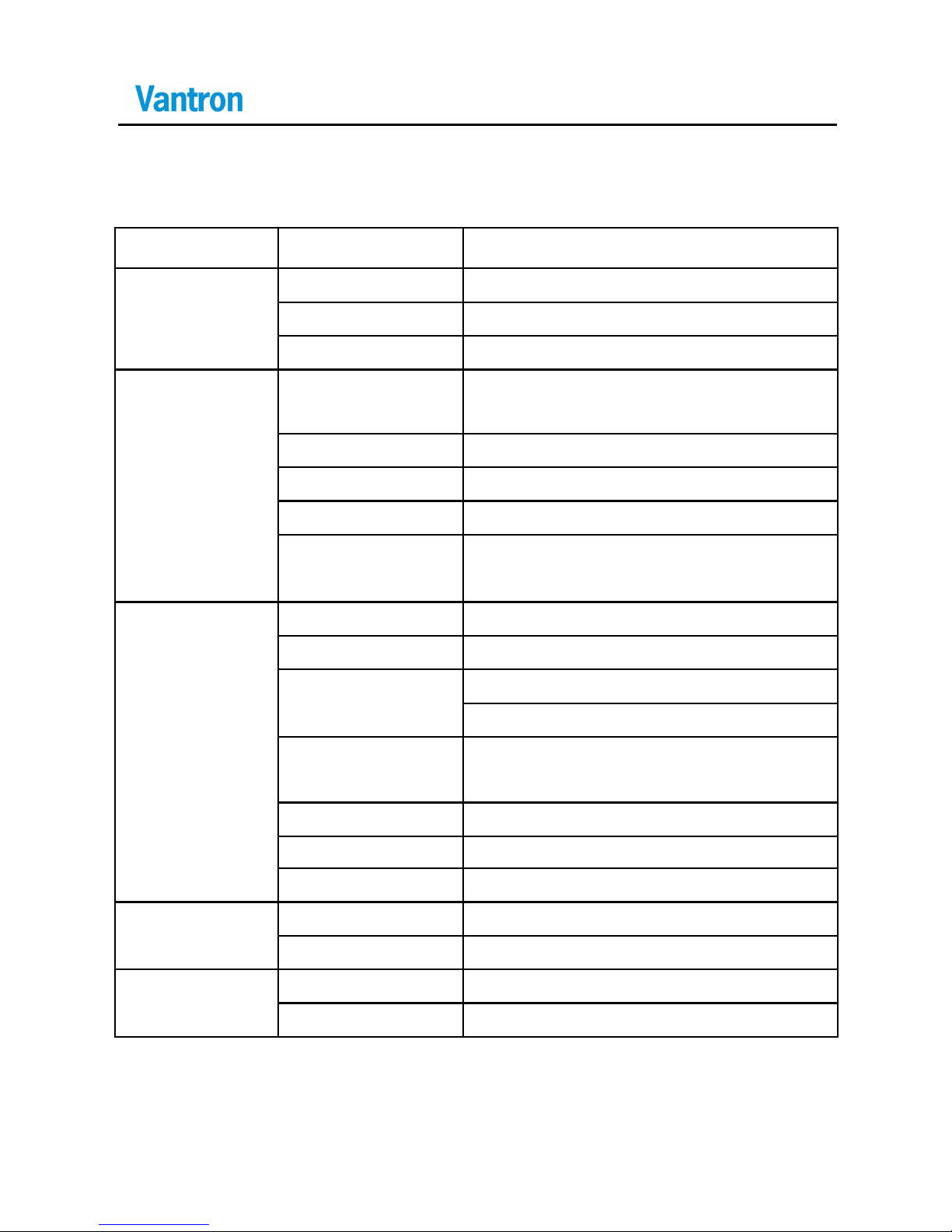
3.2 Specifications
CPU
Processor
FreeScale iMX31,ARM11, 532MHz
Memory
On Board RAM
DDR 128 MB(up to 256MB),
On Board ROM
32MB Nor Flash
External
1x MMC/SD, USB 2.0 Storage
Display
Resolution
7”,TTL TFT, 16:9, 800 x 480,
16bit Color
Contrast
500:1
Brightness
300 cd/ m2
View Angle
50U/70D,70L/70R
Touch Scr een
4 Wires resistance type, Hardness,
4H
Interfaces
Ethern et
10/100-BaseT
USB
1xUSB2.0 Host
COM Port
1xRS232(DB9),
1 x CAN 2.0b
Audio
1xMIC in 3.5mm,
1xSpeak Out 3.5mm
Alarm
Buzzer Ou t
Printer Port
Printer in USB Interface
RTC
Supported
Software
OS
WinCE 5.0/6 .0, or Linux 2.6
Applications
Provide SDK, support MCGS tool
Power
Input
DC24V (8-36V)
Consumption
8.5W
Page 16
VT-HMI-5071
12
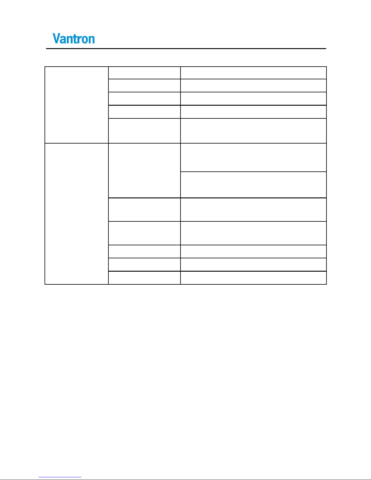
Mechanical
Dimensions
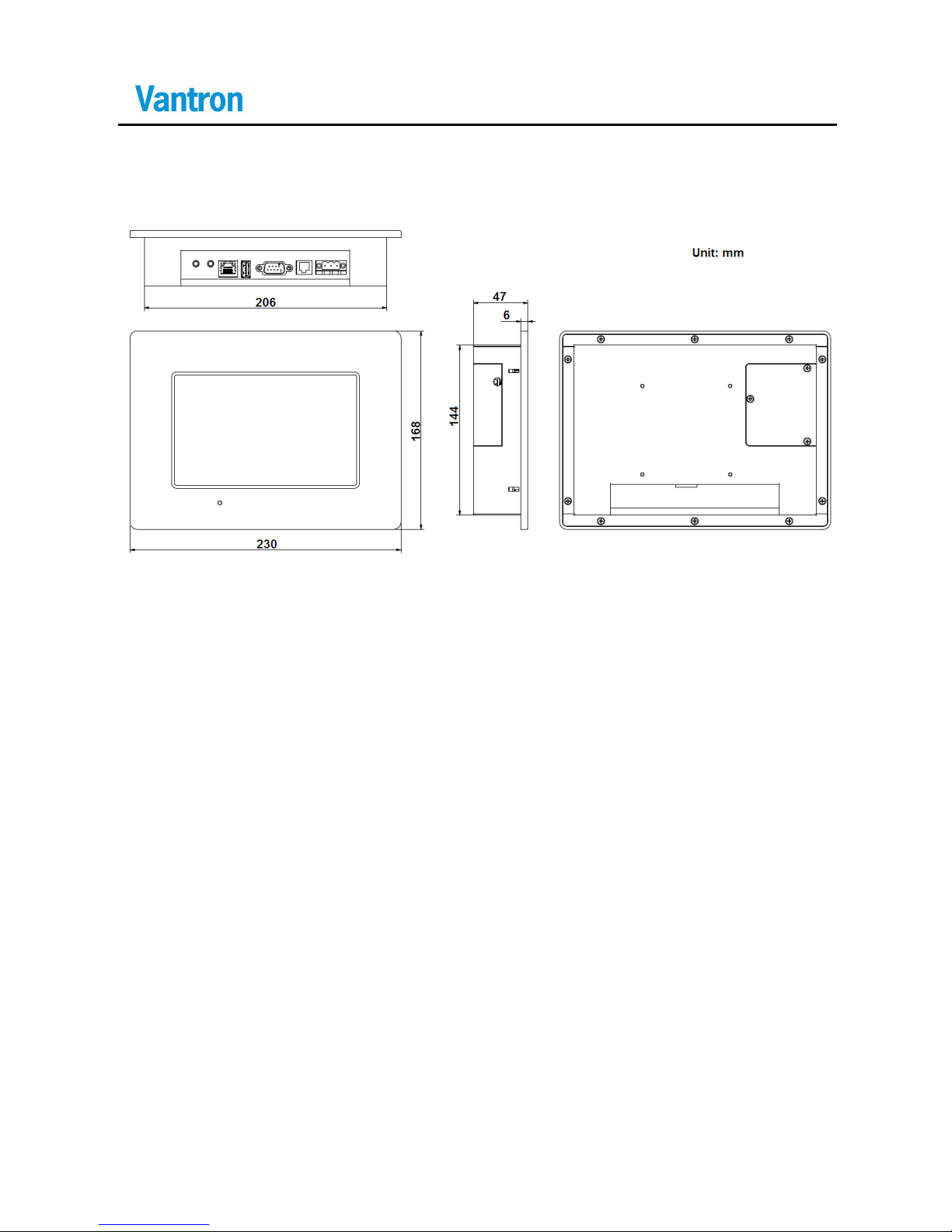
230x168 x47mm
Install Window
208x146 mm
VESA Install
75x75mm, 3mm Screw
Weight
1.2Kg
Enclosure
Aluminum Alloy with Black Color
(optional for other colors)
Environme nt
Condition
Temperature
Operating:-10℃ ~ +60℃
( ETR:-30℃ ~ +70℃ O ptional)
Storage: -20℃ ~ +70℃,
( ETR:-40℃ ~ +80℃ O ptional)
Humidity
10-85%RH (Non-Cond ensation),
operating and storage
Vibration
2G, 9-26 Hz (10 times in X,Y,Z
directions)
Protection
Front Panel: IP54 ( IP65 Optional)
Cooling Mod e
Fanless
Certifications
FCC and C E
Page 17
VT-HMI-5071
13
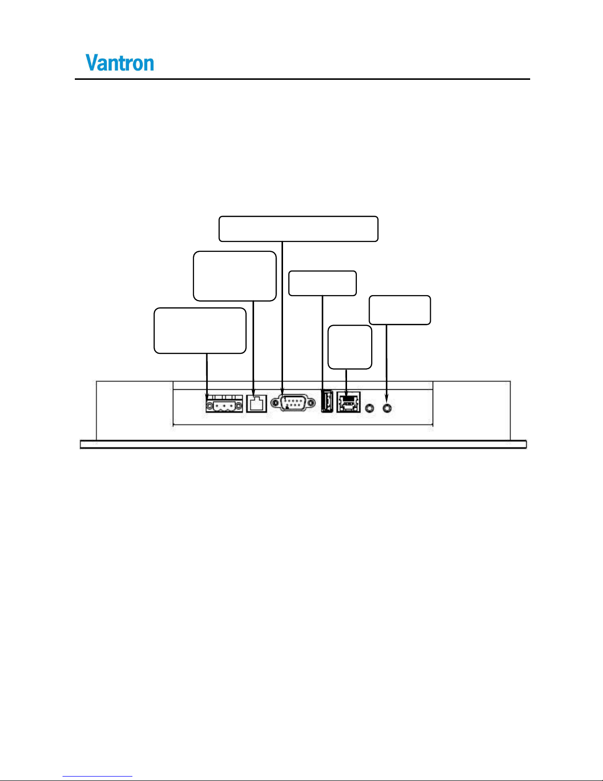
3.3 Interface Instructions
3.3.1 Bottom View
RS 485/422
Serial Port
USB Host
D Sub-9 RS232 Serial Port
Audio
12/24V Power
Input
USB
Client
Page 18
VT-HMI-5071
14
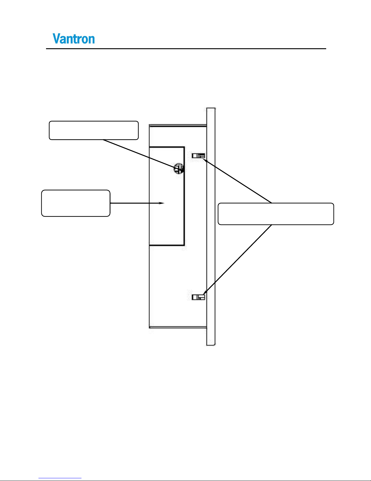
3.3.2 Left View
Mounting/Locating Holes
SD/MMC,
CAN
CAN WiringOut Hole
Page 19
VT-HMI-5071
15
3.4 Dimension
Mounting Window Size: 208x146 mm
Page 20
VT-HMI-5071
16
3.5 Hardw are Installation
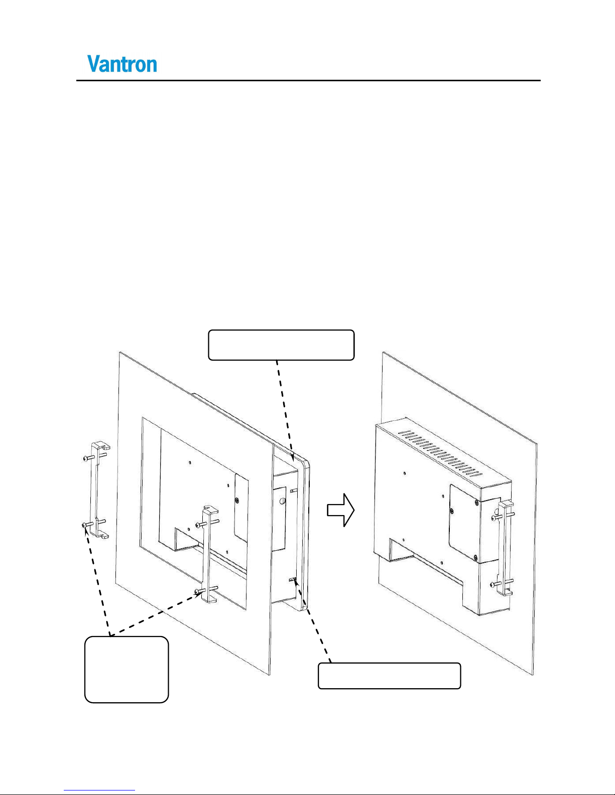
The product suppor ts standard VESA mounting (75 x 75mm x Φ 3mm)
as well as side mounting.
The left and right sides of the device housing have two mounting
slots respectively for inserting mounting brackets to n eeded positions
by tightening screws ( as shown below):
Waterproof Cushion
Mounting
Bracket
and Screw
Mounting/Locating
Page 21
VT-HMI-5071
17
3.6 Interface Description
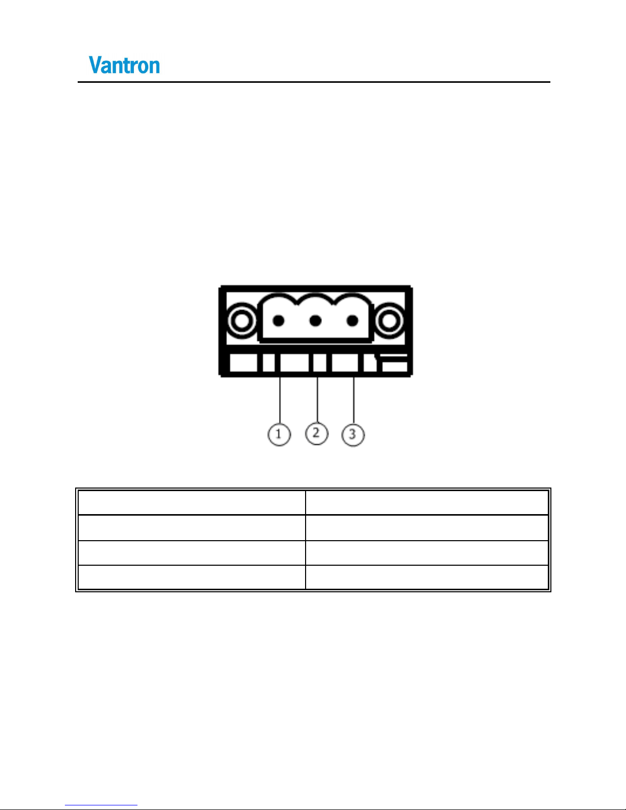
3.6.1 DC24V Power Input
3 pins 5.08mm pitch terminal with screw lock
Pin
Description
1
GND( power ground)
2
Power (+24V DC +)
3
Protection Ground
Page 22
VT-HMI-5071
18
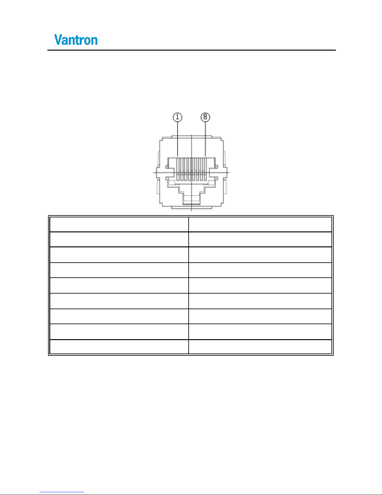
3.6.2 Ethernet Interface
Standard RJ45 interface, supporting 10M/100M self-adaptation
Pin
Description
1
TX+
2
TX-
3
RX+
4
N.C.
5
N.C.
6
RX-
7
N.C.
8
N.C.
Page 23
VT-HMI-5071
19
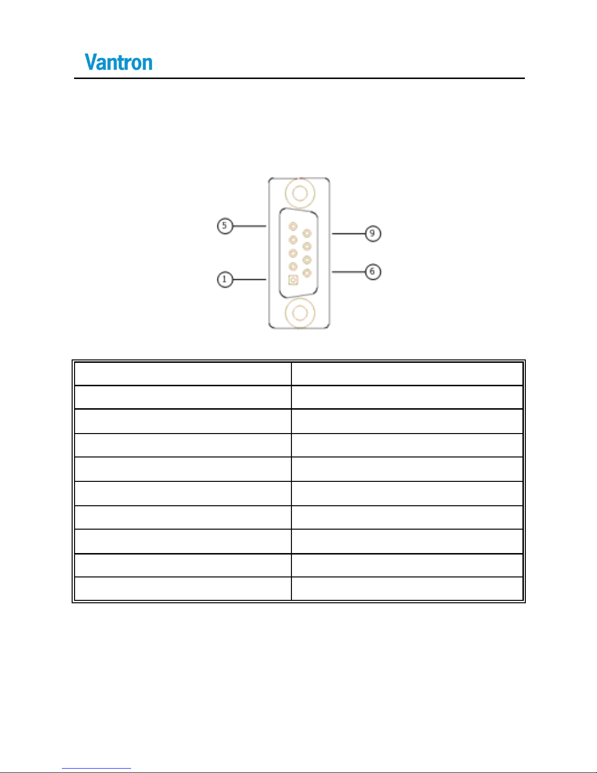
3.6.3 D Sub-9 RS232 Connector
Standard vertical DB-9 male connector, baud rate up to 921, 600bps
Pin
Description
1
DCD
2
RXD
3
TXD
4
DTR
5
GND (ground pin)
6
DSR
7
RTS
8
CTS
9
RI
Page 24
VT-HMI-5071
20
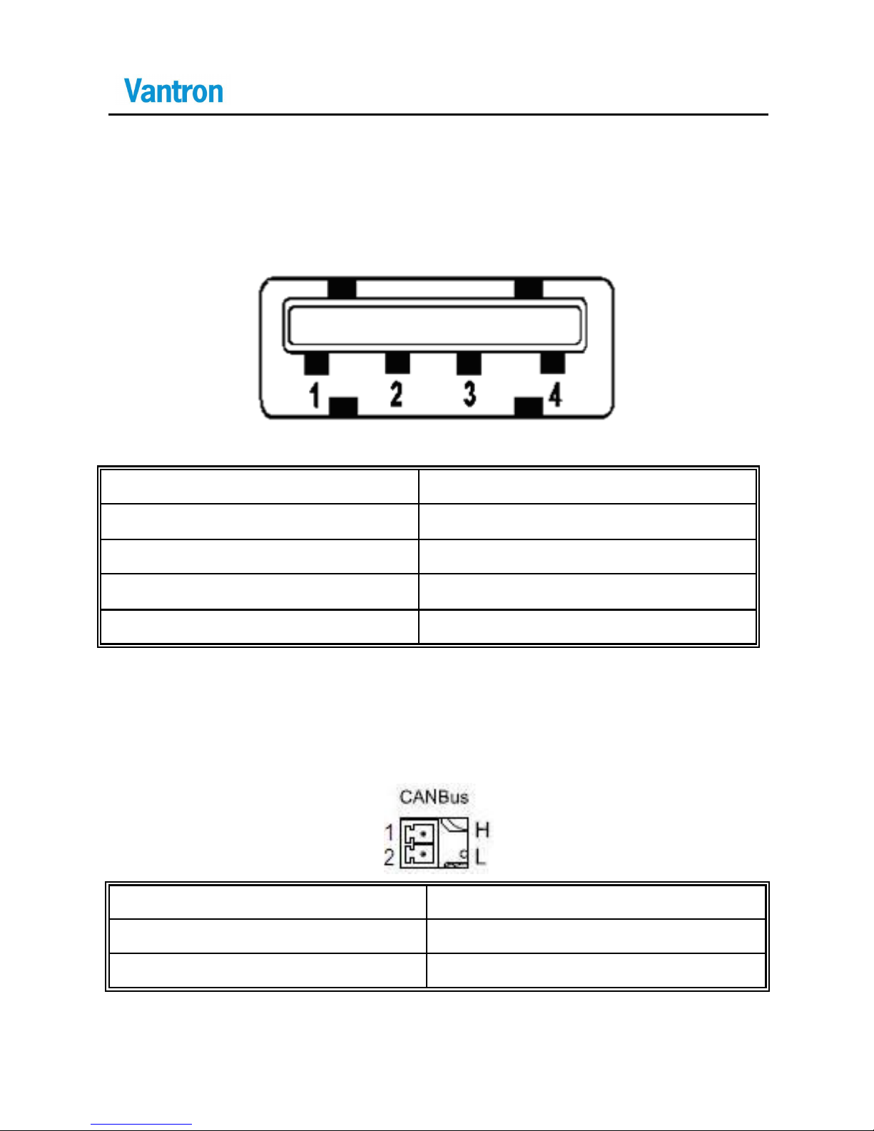
3.6.4 USB Host Connector
Standard USB host conn ector, type A
3.6.5 CAN Connector
2 Pins 3.81mm pitch terminal
Pin
Description
1
CANH
2
CANL
Pin
Description
1
USB VCC
2
USB NEG
3
USB POS
4
GND
Page 25
VT-HMI-5071
21
3.7 I/O Interface Instructions
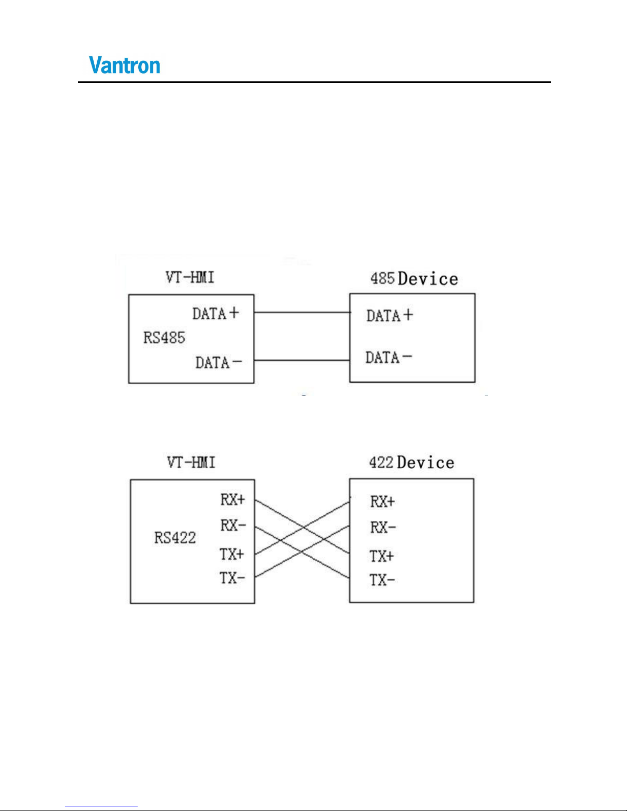
3.7.1 RS485/422
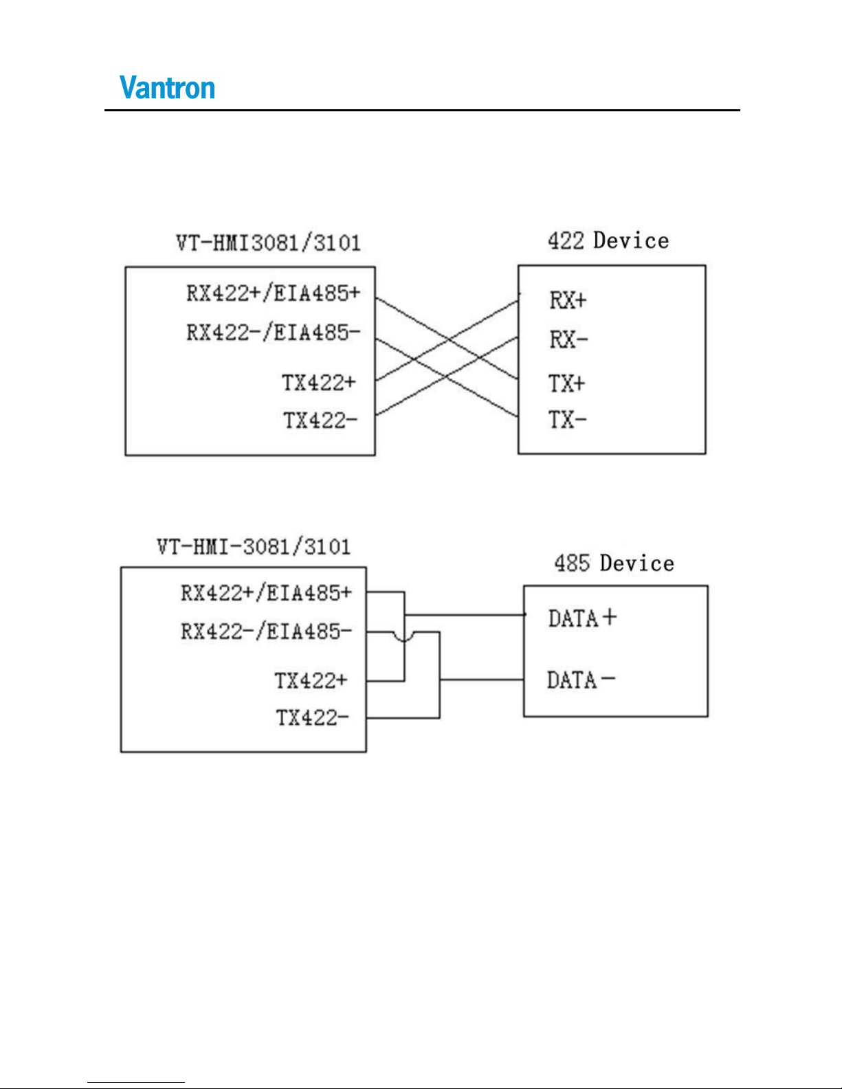
3.7.1.1 485 Cable Connection
3.7.1.2 422 Cable Connection
3.7.1.3 RS422/485
RS422 and RS485 share the same RJ11 interfac e, and the electrical
Page 26
VT-HMI-5071
22
properties thereof are determined according to different connection
modes.
RS 422 wiring suggestion
RS 485 wiring suggestion
Page 27

VT-HMI-5071
23
3.8 Packing List
No
Part Descri ption
Quantity
Type
1
Install Mechanical tools
1pcs
140040-0017EV,VANTRON
2
Cushion for Enclosure's Front
Panel Protect ion
1pc
140010-0036EV,VANTRON
3
Screw, Mounting Enclosure
4pcs
250010-01001EV,VANTRO
N
4
Power Terminal
1pc
(3pins)
210071-01041EV,
ANYTEC:VM-5.08-3P
5
CAN Bus Terminal (Optional)
1pc
(3pins)
210060-0103BEV,
ANYTEK:VM-3.81-3P
Page 28

VT-HMI-5071
24
4 Software Instructions
4.1 Brief Introduction
VT-HMI-3081 has been pre-loaded with WinCE5.0 or embedded
Linux image, so that the system can automatically run WinCE 5.0 or
embedded Linux when powered up.
4.1.1 Serial Port Instructions
VT-HMI-5071
As a default debug serial port, COM1 cannot be used by application
software nor mally. But it can be used after the debug serial port is set
to 0 or other por ts, by setting DebugPort parameters in
ADSLOAD.HWT (see 4.2.3.1).
RS485/422 is COM3.
Page 29

VT-HMI-5071
25
4.2 WinCE Instructions
4.2.1 Windows CE Application Development
4.2.1.1 Development Environment
To crea te Win32 and MFC applications with EVC4.0 and cr eate
Win32, MFC and C# applications with VS2003 、 VS2005 and VS2008,
the integrated development environment (IDE) can be purchased from
the agents of Microsoft Company.
4.2.2 Windows CE Firmware Update
1) Copy Bootloader (adsload.rom), configuration files
(adsload.hwt/adsload. Reg), OS image (nk.bin), and background
pictures (adsload.bmp) to the root directory of SD card.
2) Insert the SD card to relevant slot.
3) Power on so that the system can automatically read and update
relevant files from the SD card. The updating process can be
observed via the debug s erial port. The system continues
operating after the updating.
4) Power off.
5) Take out the SD card and delete files stored therein.
6) Power on so that the updated items can automatically load and
operate.
Page 30

VT-HMI-5071
26
Cautions:
1. It is our strong suggestion to update firmware carefully because
this product recognizes firmware o nly according to firmware name.
Therefore, it is a must to ensure that firmware in the SD card is the
required one. You may have to r eturn the product to Vantron for
maintenanc e if the updating of Bootloader(adsload.rom)fails, which
may cause loss of time and money.
2. Do not po wer off during updating.
Page 31

VT-HMI-5071
27
4.2.3 Instructions for Windows CE Config uration Files
Windows CE has two configuration files (adsload.hwt/adsload.reg)
that can be modified according to your own n eeds. It is recommended
to us e configuration files with our tech nical support. Instructions are
listed below:
4.2.3.1 Adsload.HWT
Hardware configuration files can be opened by text editor and you
therefore only need the following items and keep other items as
hardware compatible settings, the keywords and values of which
should be separated by on e or more spaces.
[TAGS]
MouseDetect 0x01
DebugPort 0x01
BootLogo 0x02
LogoBckGround 0x3B74
MouseDetect――1 : the mouse arrow can be seen after OS is
started; 0 : other values are invalid without mouse arrow.
DebugPort――designate serial port for debugging (d efault serial
port 1); 0: without debug serial port.
BootLogo――0 : Bootloader dose not display Logo; 1: display Logo
consolidated in system; 2: display Adsload.bmp (24bits or 16bits of
Page 32
VT-HMI-5071
28
bitmap files only)
LogoBckGround――designate background color (RGB565 for mat)
of Logo displayed in Bootloader.
4.2.3.2 Adsload.REG
User’s registry files can be opened by text editor and are
standardized, for example:
[HKEY_LOCAL_MACHINE\SOFTWARE\CERDISP]
"HostName"="192.168 .8.88"
"RefreshTi me"=dword: 32
"AllowRemote"=dword: 0
The system automatically loads when started and you can add
system registry information therein according to your own needs.
Notice: The last row of this file must be followed by an Enter.
Page 33
VT-HMI-5071
29
4.2.4 Notice of Touch Screen in WinCE
4.2.4.1 Touch Screen Calibration
To get better touch precision, you need to calibrate b efore
using the touch screen. The calibration comprises steps of selecting
“Start\Settings\Control Panel” to step into the control panel interface,
tapping icon to step into “Stylus Properties” interface, and
tapping “calibration” to start calibrating. You may use an auxiliary USB
mouse for stepping into “Stylus Properties” interface.
After the calibration, run “Regflushkeys.exe” command immediately
and save calibration parameters. You can either input command
“Regflushkeys.exe” in “Start\Run\”or find the progra m in
“\Windows ”directory, run it to update registry.
Page 34
VT-HMI-5071
30
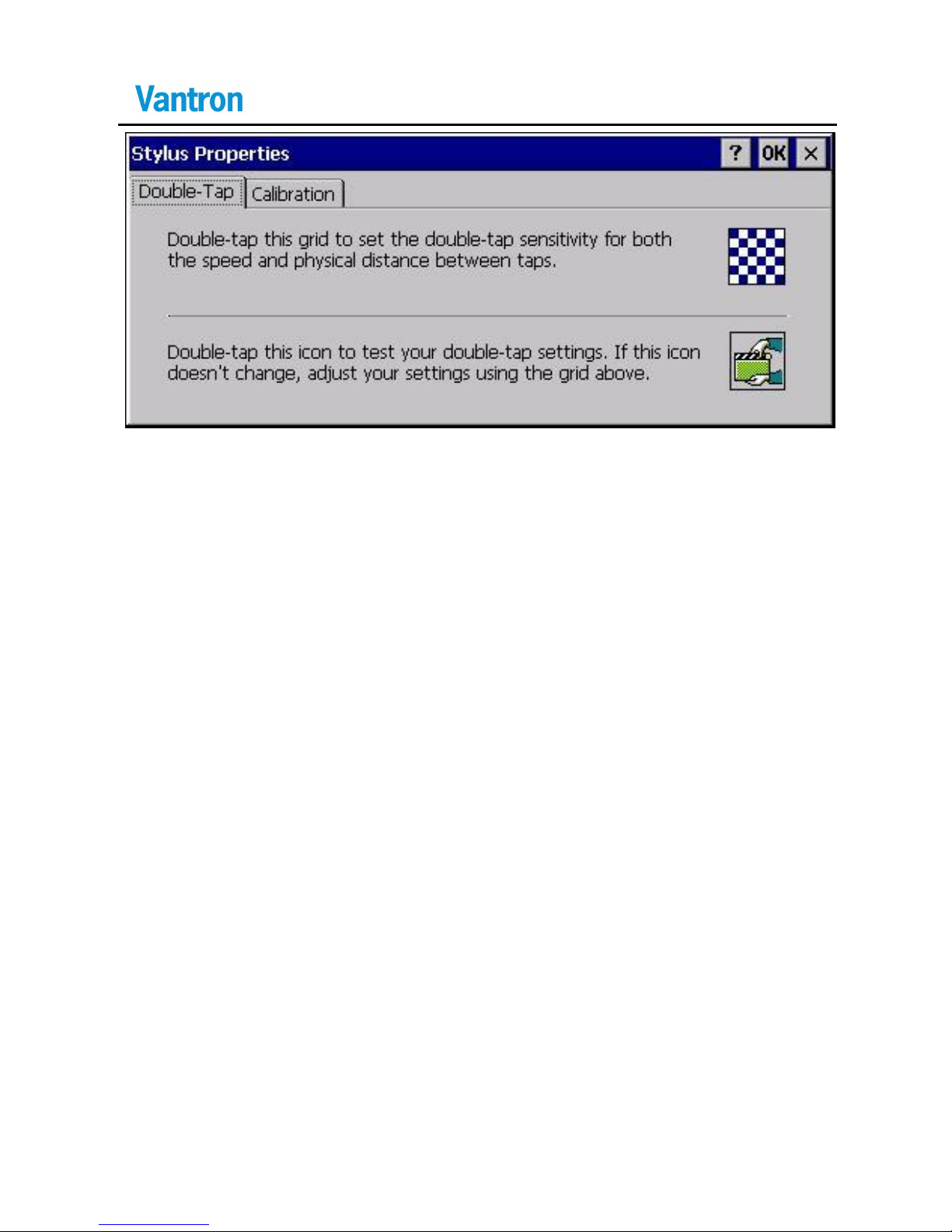
Stylus Properties Picture
4.2.4.2 Setting Touch screen sensitivi ty and speed sensitivity
The identification precision differences between finger touch and
pen touch may results in different touch screen identification effec ts.
Pen touch has better identification effect, while finger touch
(especially finger pulp touch) gets relatively poorer precision.
Therefore, it is recommended to operate with fingertips or pen,
especially at four corners and four sides so as to get op timal touch
control effect.
Meanwhile, you can get better d ouble-tap touch control effect by
setting double-tap sensitivity and physical distance parameter b etween
two taps. Set according to “Double-Tap” s election” in “Stylus
Properties ”. The physical distance between two taps is recommended
to be as great as possible for b etter finger touch effect. Run
“Regflushkeys.exe” command after the setting so as to save the
updated registry settings .
Page 35
VT-HMI-5071
31
4.3 Linux Instructions
4.3.1 Linux Application Development
4.3.1.1 Linux Application Environment
The operation environment of VT-HMI application system is a
QT/Embedded open system with the following structure:
Qt/Embedded Applications
QWS Server-Graphic Event Service
Qt/Embedded
Frame Buffer
Input Device Driver
Linux Operating System
Low-level Hardware Platform
Users can develop or transplant Qt/Embedded-based applications to
HMI platform.
4.3.1.2 Linux Application Operation
Manual operation
Copy applications to r elevant directory and op erate by
double-clicking.
Automatic operation
Copy applications to directory /etc/rcS.d and the system will
automatically operate during the next system startup.
Page 36

VT-HMI-5071
32
4.3.2 Linux Image Programming
a) Analyze u-boot and MTD partition to d etermine pro gramming
partition:
u-boot config: include/configs/adstrubog5.h
MTD driver: drivers/mtd/maps/ads -flash.c
#define CONFIG_BOOTARGS "console=ttyS0,38400
SERIALGETTY=ttyS0 "\
" SERIALBAUD=38400" \
" rw root=/dev/ram initrd=0x80800000,5m"\
" ramdisk_size=12288 rootfstype=ext2" \
" " CONFIG_MTD_PARTS
b) Analyze the configuration files of compilation kernel::
make adstrubog5_defconfig analysis:
cat ./Makefile | grep -rn "defconfig"
actual executable configuration files are
/arch/arm/configs/adsbitsyg5_defconfig
Page 37

VT-HMI-5071
33
c) mx31 small system programming
download u-boot: tftp 0x84000000 u-boot.bin // to memory
protect off 0xa0000000 0xa003ffff
erase 0xa0000000 +0x40000
cp.b 0x84000000 0xa0000000 0x40000
Download tftp 0x84000000 zImage // to memory
erase 0xa0080000 +0x200000
cp.b 0x84000000 0xa0080000 0x200000
Download ramdisk:
tftp 0x84000000 ramdisk.gz
erase 0xa0280000 +0x500000
cp.b 0x84000000 0xa0280000 0x500000
Download jffs2:
tftp 0x84000000 flashfs1 (tftp 0x84000000 rootfs.jffs2)
erase 0xa0780000 +0x1880000
cp.b 0x84000000 0xa0780000 0x1880000
bootm 0xa0080000 //boot from the kernel
Original parameter configuration:
bootargs=console=ttyS0,38400
SERIALGETTY=ttyS0 SERIALBAUD=38400 rw root=/dev/ram
initrd=0x80800000,5m ramdisk_size=12288 rootfstype=ext2
mtdparts =flash0:256k(boot),256k(bo otvars),2m(zImage),5m(ramdisk.gz
),-(flashfs1), wherein initrd designates the storage address of ramdisk
in memory; uboot loads ramdisk images to memory; the ramdisk
images are not compressed bu t loaded to root file system by the kernel.
Modify root=/dev/mtdblock4 rootfstype=jffs2 noinitrd
Page 38
VT-HMI-5071
34
set bootargs console=ttyS0,38400
SERIALGETTY=ttyS0 SERIALBAUD=38400 rw root=/dev/mtdblock4
rootfstype=jffs2 noinitrd
mtdparts =flash0:256k(boot),256k(bo otvars),2m(zImage),5m(ramdisk.gz
),-(flashfs1)
set zI mage cp.b 0xa0080000 0x84000000 0x200000 // convey to
memory from flash
set start "bootm 0x84000000"
set bootcmd "run zImage; run start"
4.3.3 Instructions for Linux Configuration Files
Modification and updating of software configurations are
dangerous and may cause system boot failure. Do not modify on your
own unless with a good knowledge of each updating files.
Page 39

VT-HMI-5071
35
4.3.4 start.txt
The system automatically updates and starts scrip without user’s
modification.
4.3.5 tty_config.txt
Configure debug s erial port and baud rate for the device.
${console}: The debug serial port adopted by th e device could be
set with values such as ttyS0, ttyS1, ttyS2, etc .
${baudrate}: The baudrate adopted by the d ebug serial port could
be 9,600,38,400,115,200, etc.
4.3.6 hw_config.txt
Configure parameters for LCD driven by the device. It functions
differently according to different types of device.
Hardware compatibility settings must be kept without
random modification.
Page 40
VT-HMI-5071
36
4.3.7 root_config.txt
Configure items for automatic updating and boot parameters that
will be adopted during the boot of updated system, for example:
images_to_flash='boot zImage ramdisk.gz flashfs1' is for designating
items that need updating.
U-boot image: boot
Linux knernal image: zImage
Linux Ramdisk file system image: ramdisk.gz
Linux jffs2 file system image: jffs2
Files designated by image_to_flash variables must exist in the
SD card or USB.
Page 41
VT-HMI-5071
37
4.3.8 Notice of Touch Screen in Linux
4.3.8.1 Touch Screen Calibration
To get better touch control precision, it is needed to
calibrate before using the touch screen, generally get electrified on
equipment for the first time. The program prompts for automatic
calibration if the touch screen is not calibrated. The system
automatically saves calibration parameter after the calibration.
Two methods for stepping into the “calibration” interface are listed
below if fur ther calibration is needed:
a) select “Start\Recalibration” command from the menu to step into
“calibration” interface.
b) tap “Stylus” icon in “ s etting” bar to step into “ calibration”
interface.
Page 42
VT-HMI-5071
38
5 Tips
Waste Disposal
It is recommended to disassemble the device before abandoning it in
conformity with local regulations. Please ensure that the abandoned
batteries are disposed according to local regulations on waste disposal.
Do not throw batteries into fire (explosive) or put in common waste
canister. Products or product packages with the sign of “explosive”
should not be disposed like household waste but delivered to
specialized electrical & electronic waste recycling/disposal center.
Proper disposal of this sort of waste helps avoiding harm and adverse
effec t upon surroundings and people’s health. Please contact local
organizations or recycling/disposal center for more recycling/disposal
methods of related products.
Comply with the following safety tips:
Do not use in combustible and explosive environment
Keep away from combustible and explosive environment for fear of
danger.
Page 43
VT-HMI-5071
39
Keep away from all energized circuits.
Operators should not remove enclosure from the device. Only the
group or person with factory certification is permitted to open the
enclosure to adjust and replace the structure a nd components of the
device. Do not change components unless the power cord is removed.
In some cases, the device may still have residual voltage even if the
power cord is removed. Therefore, it is a must to remove and fully
discharge the device before contact so as to avoid injury.
Unauthorized changes to this product or its components are
prohibited.
In the aim of avoiding accidents as far as possible, it is not allowed to
replace the system or change components unless with permission and
certificati on. Please contact the technical department of Vantron or
local branches for help.
Pay attention to caution signs.
Caution signs in this manual remind of possible danger. Please comply
with relevant safety tips below each sign. Meanwhile, you should s trictly
conform to all safety tips for operation environment.
Page 44

VT-HMI-5071
40
Notice
Considering that reasonable efforts have been made to assure
accuracy of this manual, Vantron assumes no responsibility of possible
missing contents and information, errors in contents, citations,
examples, and source programs.
Vantron reserves the right to make necessary changes to this manual
without prior notice. No part of this manual may be reprinted or publicly
released in forms of photocopy, tape, broadcast, e-document, etc.
Page 45

VT-HMI-5071
41
Chengdu Vantron Technology Ltd.
www.vantrontech.com.cn.
Phone: (+86)28- 85123930 85123931
85157572 85156320
Fax: (+86)28-85123935
E-mail: [email protected]
 Loading...