


Comfort & Control
Communicating Thermostat
Installation Manual
CC-STAT
VANTAGE

Table Of Contents
SECTION ONE – INSTALLATION OVERVIEW ............................................................................. 1
Installation Location Recommendations ................................................................................. 1
Thermostat Mounting ....................................................................................................................... 1
CC-STAT Optional Support Modules & Sensors .................................................................. 2
Outdoor Temperature Sensor (Optional) ............................................................................... 2
Remote Temperature Sensors (Optional) .............................................................................. 3
Temperature Averaging .................................................................................................................. 3
Power & Reset Options .................................................................................................................. 4
Thermostat Wiring Terminal ........................................................................................................ 4
Conventional Heat/Cool Wiring .................................................................................................. 5
Single Transformer (Use Jumper Wire From RC to RH) ............................................. 5
Two Transformers (Remove Jumper Wire From RC to RH) ..................................... 5
Heat Pump Wiring ................................................................................................................................ 6
Single Transformer (Use Jumper Wire) ............................................................................. 6
Two Transformers (Remove Jumper Wire) ...................................................................... 6
Humidistat ............................................................................................................................................. 7
Dry Contact ...................................................................................................................................... 7
Powered Contact ........................................................................................................................... 7
Vantage Integration .......................................................................................................................... 8
Wiring to CC-WLINT or CC-RLINT For HVAC or Humidity Control .................... 10
Design Center Integration Overview ...................................................................................... 10
SECTION TWO – SETUP & TESTING ............................................................................................ 12
Equipment Type Selection Switch (SWS1) .......................................................................... 12
Installer Setup Menu ....................................................................................................................... 12
Installer System Settings Table ................................................................................................. 13
Installer System Settings Table (continued)....................................................................... 14
Installer System Settings Table (continued)....................................................................... 15
System Test Menu ........................................................................................................................... 16
System Test Tables ......................................................................................................................... 17
SECTION THREE – QUICK REFERENCE TO CONTROLS & DISPLAY ............................ 18
Home Screen ...................................................................................................................................... 18
Main Menu ........................................................................................................................................... 18
Humidistat ........................................................................................................................................... 19
SECTION FOUR – THERMOSTAT FEATURES ......................................................................... 20
SECTION FIVE – TROUBLESHOOTING ....................................................................................... 21
SECTION SIX – ERROR CODES ..................................................................................................... 22
SECTION SEVEN – SPECIFICATIONS ......................................................................................... 23
Important
Update
Information
Please visit the Vantage dealer site for updates to
Installation Manual.
Copyright Information
Vantage Controls, Vantage, InFusion, Design Center, QLink, and other selected art work, brand and
product names and designs are copyrighted, trademarks or registered trademarks of Vantage
Controls. All other art work, brand and product names and designs are copyrighted, trademarks or
registered trademarks of their respective companies.

SECTION ONE - Installation CC-STAT
©Vantage, 41184 / IS-1308191-A page 1 of 23
SECTION ONE – INSTALLATION OVERVIEW
Read this entire manual for complete understanding of installation procedures and concepts
before installing.
1. 120 volts may cause serious injury from electrical shock. Disconnect electrical power to
the HVAC system before starting installation. This system is a low-voltage system.
2. Improper installation may cause serious injury from electrical shock. HVAC systems must
be installed by a qualified contractor in accordance with NEC Standards and applicable
local and state codes.
3. Installation of Vantage products should be performed or supervised by a Certified
Vantage Installer.
4. DISCONNECT POWER TO ALL HVAC EQUIPMENT AND/OR ZONE CONTROL PANELS
If the thermostats are wired to a zone control panel, there is generally one set of
input terminals supplying power to the thermostats and dampers. This must be
disconnected.
If the thermostats are wired directly to HVAC equipment, the power must be shut off
at the equipment. This can generally be accomplished by turning off the disconnect
switch located near the equipment. If an obvious disconnect switch is unavailable, you
will need to turn the circuit off using the fuse or circuit breaker. Remove the fuse or
shut down the circuit breaker serving the equipment.
5. Failure to disconnect power could result in damage to the HVAC equipment or
thermostats. Leave power disconnected until all other electrical connections have been
made and checked for accuracy.
Thermostats should be mounted:
On an interior wall, in a frequently
occupied space.
Approximately 5 feet above floor.
At least 18” from outside wall.
Thermostat can be mounted to a vertical
junction box.
Do not mount thermostat:
Behind doors, in corners or other dead air
spaces.
In direct sunlight, near lighting fixtures, or
other appliances that give off heat.
On an outside or unconditioned area wall.
In the flow of a supply register, in
stairwells, or near outside doors.
On a wall with concealed pipes or
ductwork.
Thermostat Mounting
1. Remove the rear mounting plate from the
thermostat.
2. Pull wires through the opening in the rear
mounting plate.
3. Position and level the mounting plate of
the thermostat on wall and mark the hole
locations with a pencil.*
4. Drill 1/4” holes and insert supplied anchors
(drywall only).
5. Place mounting plate over anchors, insert
and tighten screws.
*The mounting plate may be anchored to a
single gang box.
TIP: The CC-WLINT/RLINT will fit through the
hole in the rear mounting plate.
6. Seal wire entry holes to prevent drafts
affecting temperature readings.
Installation Location Recommendations
W
ARNING
–
CAUTION
SECTION ONE - Installation CC-STAT
©Vantage, 41184 / IS-1308191-A page 2 of 23
Outdoor Sensor,
part #
SENSOR-ODT
CC-STAT Optional Support Modules & Sensors
These support modules can be added when remote temperature or humidity sensor values are needed.
Support modules can also be used for sensor averaging in large areas (see
Maximum Wiring Distances
below). Support modules must be used in
Control Mode
, see instructions shipped with module.
Support Modules:
Model CC-TEMPSUP Support Module
Provides two temperature values.
1 onboard or remote temperature sensor
1 remote temperature sensor
See additional instructions packaged with
support module
Model CC-HUMIDSUP Support Module
Provides one temperature and one humidity
value.
1 onboard humidity sensor
1 onboard or remote temperature sensor
See additional instructions packaged with
support module
These sensors can be directly wired to the CC-STAT thermostat, the CC-TEMPSUP, or to the
CC-HUMIDSUP. See additional instructions packaged with each sensor.
Remote Sensors:
Model: SENSOR-ODT MODEL: FLUSHSENSOR MODEL: SENSOR-SMT
Maximum Wiring Distances
From To Maximum Distance
InFusion Controller
CC-WLINT
(Vantage station bus specification)
1000 ft.
CC-WLINT Thermostat
4000 ft. (cumulative)
Thermostat Support Module
1000 ft. (cumulative)
Support Module Temperature Sensor Option
300 ft.
Thermostat Temperature Sensor Option
300 ft.
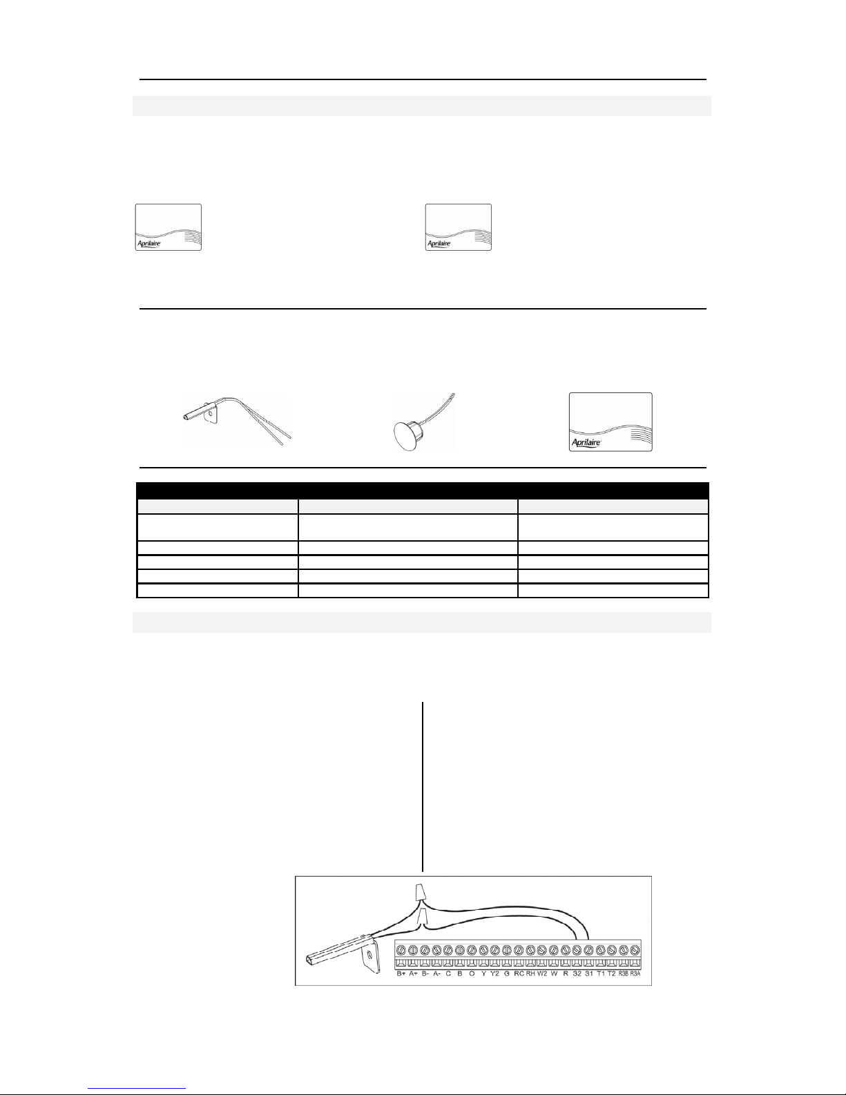
Outdoor Temperature Sensor (Optional)
Outdoor temperature can be measured by attaching Vantage’s SENSOR-ODT, outdoor sensor to
the S1 and S2 terminals on the thermostat base. The sensor must be enabled in the thermostat’s
installer setup menu. (See Installer Setup Menu in SECTION TWO – SETUP & TESTING.)
In heat pump mode the outdoor
temperature sensor can be used to
efficiently utilize an air source heat pump:
When the outdoor temperature is less than
the Low Balance Point, the heat pump will
be locked out and only auxiliary heating
will be used.
When the outdoor temperature is higher
than the High Balance Point, the auxiliary
heating will be locked out and only the
heat pump will be used to provide heating.
Outdoor temperature sensor should be
mounded:
On side of building out of direct sunlight
(north side recommended).
Above snow line.
At least 3’ away from exhaust vents and
condensing lines.
Using no more than 300’ of wire. (For
longer runs, use the CC-TEMPSUP as a
bridge).
Do not route wires along 120 VAC lines.

SECTION ONE - Installation CC-STAT
©Vantage, 41184 / IS-1308191-A page 3 of 23
2-WIRE
Thermostat Cable
(R=Red, W=White
2-WIRE
Thermostat Cable
(R=Red, W=White
Remote Temperature Sensors (Optional)
A remote indoor temperature sensor can be used if the thermostat is to be mounted in a
concealed location. A Vantage flush mount sensor, part number FLUSHSENSOR, or surface
mount sensor, part number SENSOR-SMT, can be attached to the T1 and T2 terminals and
mounted in a recommended area. The remote sensor must be enabled in the installer set-up
menu, and once enabled will override the thermostat’s internal temperature sensor. (See Installer
Setup Menu in SECTION TWO – SETUP & TESTING). For temperature averaging connect 4 or 9
indoor sensors as illustrated below.
Remote temperature sensor should be
mounted:
On an interior wall, in a frequently
occupied space.
Approximately 5‘ above floor.
At least 18” from outside wall.
Using less than 300’ of wire.
Do not mount remote sensor:
Behind doors, in corners or other dead air
spaces.
In direct sunlight, near lighting fixtures, or
other appliances that give off heat.
On an outside or unconditioned area wall.
In the flow of a supply register, in
stairwells, or near outside doors.
On a wall with concealed pipes or
ductwork.
Near 120 VAC lines
Temperature Averaging
Connect Multiple Thermostat Sensors for Temperature Averaging.
Only 4 or 9 sensor configurations are allowed for averaging. Only wire multiple sensors as shown.
FOUR SENSOR TEMPERATURE
AVERAGING – SCHEMATIC
4 sensors, (see additional
information shipped with sensor)
NOTE 1: Wiring shown is using
model FLUSHSENSOR. Use the
same wiring for model SENSORSMT.
NINE SENSOR TEMPERATURE
AVERAGING –
SCHEMATIC
9 sensors, (see
additional information
shipped with sensor)
NOTE 2: Temperature
averaging using the
CC-TEMPSUP support
module’s built-in
temperature sensor
allows averaging 2, 3,
or 4 sensors. See
additional instructions
packaged with
support module.
Flush Mount Sensor,
part # FLUSHSENSOR
Surface Mount Sensor,
part # SENSOR-SMT

SECTION ONE - Installation CC-STAT
©Vantage, 41184 / IS-1308191-A page 4 of 23
Power & Reset Options
The InFusion System retains settings in the event of a power outage. When power is restored, all
settings, including Network Override aka Occupied/Unoccupied modes are restored. The reset*
button located under the battery cover can be used to reset the thermostat to factory defaults.
*CAUTION: Thermostat power must be cycled after a reset for the CC-WLINT or CC-RLINT
stations to operate correctly.
Thermostat Wiring Terminal
Wire specifications:
18-24 gauge thermostat wire
CAT-5 or equivalent for communication
terminals
Vantage Station Bus – see page 9
Installation notes:
Ensure power at the thermostat location is
off.
Loosen screw terminals, insert stripped
wire and re-tighten. See Wiring to CC-
WLINT or CC-RLINT For HVAC or
Humidity Control in SECTION TWO.
Push the excess wire back into the
opening and plug the wall opening to
prevent drafts.
Note 1: If the Vantage thermostat is replacing
an old thermostat, check whether the old
thermostat is powered from an external
24VAC transformer or through the RC or RH
terminals. If thermostat power is provided by
an external 24VAC source do not jumper
from the R terminal to either the RC or the
RH terminal. The C* terminal should have
connections from the HVAC equipment, an
external 24VAC transformer (if it exists) and
the CC-WLINT or the CC-RLINT interface
station.
* Note 2: Older systems may not have a C
(common) wire. If a common wire is not
available from the HVAC equipment please
see the auxiliary switch solution from
Vantage, part number STAT-AUXS. This part
adapts existing 3 or 4 wire systems to 4 or 5
wire systems requiring a common
connection. Detailed instructions are
included with the STAT-AUXS.
Key
B+ / B-
Receive communication terminal
(reference CC-WLINT & CC-RLINT)
1
A+ / A-
Transmit communication terminal
(reference CC-WLINT & CC-RLINT)
1
C
24VAC common from HVAC or
external 24VAC
B
Reversing valve for heat
2
O
Reversing valve for cool
2
Y
1st stage cooling / compressor or
dehumidifier
3
Y2
2nd stage cooling / compressor
G
Fan
RC
24VAC supply cooling
4
RH
24VAC supply heating
4
W2
2nd stage heat / auxiliary / E-Heat
W
1st stage heat / auxiliary / E-Heat /
humidifier
3
R
24VAC Thermostat power (hot) from
HVAC or external 24VAC
S2 & S1
outdoor temperature sensor
(optional)
T1 & T2
remote temperature sensor
(optional)
RSB & RSA
CC-TEMPSUP or CC-HUMIDSUP
Support Module communication (half
duplex)5
1
Refer to Vantage Integration later in this
instruction and Vantage CC-WLINT / CCRLINT Installation instructions.
2
O and B terminals are both de-energized when
system mode is OFF or in AUTO when the
heating and cooling equipment is idle.
3
When the unit is configured for humidistat
mode.
4
Jumper between RC & RH is used in single
transformer systems (see wiring diagrams).
5
See Support Modules referenced earlier in this
instruction or refer to the Support Module’s
literature for wiring details – shipped with
each support module
.

SECTION ONE - Installation CC-STAT
©Vantage, 41184 / IS-1308191-A page 5 of 23
Conventional Heat/Cool Wiring
Single Transformer (Use Jumper Wire From RC to RH)
Never place jumper wire from RC or RH to R when R is powered from external source.
Two Transformers (Remove Jumper Wire From RC to RH)
Never place jumper wire from RC or RH to R when R is powered from external source.

SECTION ONE - Installation CC-STAT
©Vantage, 41184 / IS-1308191-A page 6 of 23
Heat Pump Wiring
(See Section Two for changing thermostat to Heat Pump mode.)
Single Transformer (Use Jumper Wire)
NOTE: “O” is active in cooling and “B” is active in heating.
Never place jumper wire from RC or RH to R when R is powered from external source.
Two Transformers (Remove Jumper Wire)
NOTE: “O” is active in cooling and “B” is active in heating.
Never place jumper wire from RC or RH to R when R is powered from external source.

SECTION ONE - Installation CC-STAT
©Vantage, 41184 / IS-1308191-A page 7 of 23
THERMOSTAT IS
POWERED FROM
EQUIPMENT OR
24VAC TRANS.
THERMOSTAT IS
POWERED FROM
EQUIPMENT OR
24VAC TRANS.
Humidistat
Dry Contact
Powered Contact

SECTION ONE - Installation CC-STAT
©Vantage, 41184 / IS-1308191-A page 8 of 23
Vantage Integration
CC-STAT-WL-KIT / CC-STAT-RL-KIT Setup And Configuration
CC-WLINT, WireLink™ or the CC-RLINT, RadioLink® thermostat interface stations provide bidirectional communication between the Vantage control system and the HVAC system. Any
button or time control using InFusion Design Center can be programmed to change Setpoints,
Mode, Fan, Network Override (formerly Occupied/Unoccupied mode), etc., on any thermostat.
Setpoints, Indoor/Outdoor temperatures, Mode, Fan (status) and Occupied/Unoccupied (status)
may be displayed on Vantage LCD TPT stations, etc. A Vantage CC-WLINT or CC-RLINT station
and a Vantage thermostat are used together to control HVAC systems. Typically when a
thermostat is ordered the interface station, CC-WLINT, WireLink or the CC-RLINT, RadioLink, is
included (KIT part numbers above).
Backward Compatibility
The CC-STAT thermostat will not work with the Q-ETS3-WireLink or STHERR101-RadioLink
interface stations. However, an existing Vantage system (InFusion or Q Systems), with an older
thermostat and Q-ETS3 or STHERR101, can be updated by simply: 1) replacing the old thermostat
with a new CC-STAT, 2) replacing the old interface station with a new CC-WLINT or CC-RLINT,
3) replacing the serial number of the old Q-ETS3 or STHERR101 with the new serial number of the
CC-WLINT or CC-RLINT in the project file and finally, 4) updating the controller. No additional
programming is required unless the installer wants to take advantage of the new thermostat
features. The Project must be an InFusion System to take advantage of the new thermostat
features. To take advantage of the new thermostat features please follow these steps:
add the new thermostat to the project file,
use the Replacement Wizard (select Edit from the menu bar) to convert most tasks to the new
thermostat,
o in the Replacement Wizard select the old thermostat (only select one) and click Next>,
o select the new thermostat (NOTE: A list of supported tasks is displayed – the list for this
object is not editable),
o click on Finish, the tasks for the old thermostat will now control the new thermostat,
thermostat Objects in TPT screens are not updated by the Replacement Wizard,
o in Touchscreen Designer, edit each TPT thermostat object and manually select the new
thermostat,
Repeat this process for each thermostat.
CC-WLINT & CC-RLINT Specifications
Each Vantage thermostat requires a CC-WLINT or CC-RLINT:
Specifications CC-WLINT WireLink CC-RLINT RadioLink
Dimensions HWD
1.875” x 1.5” x 0.375”
47.6mm x 38mm x 10mm
1.875” x 1.5” x 0.5”
114mm x 38mm x 19mm
Weight 0.8oz - 23g 1.4oz - 40g
Station Power
connections
24Volt AC from thermostat base 24Volt AC from thermostat base
Station Count Design
Center
0.36W on IC-24V
0.54W on IC-36V*
1 RadioLink Station
Station Count QLink 1 WireLink Station 1 RadioLink Station
Status LED Indicator Yes Yes
I/O LED Indicators Yes Yes
Ambient Operating
Temperature
32-95°F -or- 0-35°C
Ambient Operating
Humidity
5-95% non-condensing
Software/Firmware
Vantage’s new thermostat and interface stations are compatible with InFusion Design Center
software version 3.0.56 software or higher and controller firmware 3.0.50 or higher, however, as
stated above, the new thermostat parts may be “dropped-in” with only a serial number change.
For new projects it is recommended that firmware and software be kept to the most current
release.

SECTION ONE - Installation CC-STAT
©Vantage, 41184 / IS-1308191-A page 9 of 23
Station Bus Connection
The CC-WLINT connects to the Vantage System Station Bus using the two black wires labeled
Station Bus. The Station Bus wire should comply with the Vantage station bus specification*. The
CC-RLINT connects to the Vantage System via a RadioLink enabled system.
* Vantage Station Bus Wire Specification
2C, 16AWG / 1.31mm2, twisted, non-shielded, <30pF per foot. Separate a minimum
of 12" / 30.5cm from other parallel communication and/or high voltage runs.
Mounting the CC-WLINT or CC-RLINT
The CC-WLINT or CC-RLINT may be mounted behind the thermostat in a single gang box or may
hang through a small hole in the wall. The CC-WLINT or CC-RLINT does not supply power to the
thermostat.
Configuration
When the CC-WLINT or CC-RLINT is properly connected and powered the status LED will have a
two blink pattern for the WireLink model or a three blink pattern for the RadioLink model which
typically means it is not configured. NOTE: The LCD screen does not indicate that it is not
configured. From Design Center, with the station highlighted, click on the Configure Stations
button on the toolbar menu and wait for the station to display the following scrolling message,
PRESS HOLD TO CONFIGURE / VANTAGE CONFIGURATION. Press and release the HOLD
button, wait for one or two seconds, and verify that the serial number was populated in Design
Center. Repeat if necessary. Two additional ways to configure: 1) Follow the steps above but
press the configure button on the CC-WLINT or CC-RLINT station. The button is located on the
same side as the LED lights, near the middle of the board as illustrated below. The button may be
pressed by pressing the shrink-wrap directly over the button. 2) The station may also be
configured by typing the serial number in
the project file, using this method the
station will automatically be configured
when the system is programmed. Once
configured the status LED on the CCWLINT or CC-RLINT will blink evenly.
Status LED Diagnostic Information for CC-WLINT or CC-RLINT
During setup and configuration the CC-WLINT or CC-RLINT LED will blink at different intervals.
The STATUS LED blinks evenly or flashes 2, 3, 4, 5, or 6 times followed by a pause to indicate
status information.
One Even blink: The CC-WLINT or CC-RLINT is correctly configured on programmed system.
Two blinks: CC-WLINT or CC-RLINT is operating correctly but is not configured.
Three blinks: CC-WLINT or CC-RLINT is not communicating with the Controller. For the CCWLINT, verify that station bus wiring conforms to Vantage guidelines. For the CC-RLINT, verify
that the serial number is correct in the software and is in communication range with the
RadioLink Enabler.
Four blinks: CC-WLINT or CC-RLINT Factory problem. Please contact the factory.
Five blinks: CC-WLINT (only) Configuration mode.
Six blinks: Thermostat is not connected to the base after system has been programmed.
Configure Button

SECTION ONE - Installation CC-STAT
©Vantage, 41184 / IS-1308191-A page 10 of 23
Note: If model CC-RLINT
this side is the antenna; do
not cut, strip, or bend
antenna
The R terminal must be
powered from an external
24VAC source or by
jumping power from RC or
RH to R. The R terminal
must only have power
from a single source.
Wiring to CC-WLINT or CC-RLINT For HVAC or Humidity Control
Design Center Integration Overview
Thermostat Setup with InFusion
In Area View select the floor and room for the thermostat. Click on Vantage Objects in the Object
Explorer and expand Stations, WireLink or Stations, RadioLink and double click on the thermostat
station to add it to the room. In the Object Editor name the station and make sure it is on the
correct station bus. At the bottom of the Object Explorer Check boxes are provided for external
sensors, etc.
Globally Display Outdoor Sensor
In Design Center, click on Settings | Project Preferences | Thermostat and the Global Sensor drop
down list. Select the thermostat that has the external sensor. This will broadcast the value of the
external sensor to all thermostats connected to the Vantage System, as long as they do not
already have an outdoor sensor directly connected. If no thermostat is selected only the
thermostats with an outdoor sensor connected will display the outdoor temperature. Remember
to enable the outdoor sensor in the Installer Setup Menu on the thermostat’s local interface.
Network Override
Network Override uses boolean logic – set to True or False. Compare this new command to
previous thermostat states of Day/Night or Occupied/Unoccupied. When the thermostat is in
Network Override, InFusion time controls, etc. are ignored – unless the command also sets the
Network Override state to False. When Network Override is disabled the last commands sent will
be executed. For example, while in Network Override the cool or heat setpoints may be changed
and the thermostat’s operation mode may be changed, when Network Override is returned to

SECTION ONE - Installation CC-STAT
©Vantage, 41184 / IS-1308191-A page 11 of 23
This device complies with part 15 of the FCC rules and Industry Canada ICES-003. Operation is
subject to the following two conditions: (1) This device may not cause harmful interference,
and (2) this device must accept any interference received, including interference that may
cause undesired operation. Any changes or modifications not expressly approved by Vantage
Controls could void the user’s authority to operate the equipment.
Le présent appareil est conforme aux CNR d’Industrie Canada applicables aux appareils radio
exempts de licence. L’exploitation est autorisée aux deux conditions suivantes: (1) l’appareil
ne doit pas produire de brouillage, et (2) l’utilisateur de l’appareil doit accepter tout
brouillage radioélectrique subi, meme si le brouillage est susceptible d’en compromettre le
fonctionnement.
IMPORTANT! Any changes or modifications not expressly approved by the part responsible for
compliance could void the user’s authority to operate this equipment.
IMPORTANT! Tous les changements ou modifications pas expressément approuvés par la partie
responsable de la conformité ont pu vider l’autorité de l’utilisateur pour actioner cet
équipment
false, the last sent cool and heat setpoints and operation mode commands will be
executed/pushed to the thermostat.
While in Network Override change the Cool and Heat setpoints manually on the thermostat
directly. These setpoints are saved in the CC-WLINT or CC-RLINT. This allows another way of
quickly setting “away/vacation” setpoints while disabling commands sent from Design Center, by
simply placing the thermostat into Network Override. If the Network Override feature of the
thermostat is not wanted, avoid accidental use of this feature by setting it to disabled in the
Installer Setup Menu on the thermostat’s local interface.
TIP: If Network Override has been disabled it is important to not
program any task in Design
Center that will set Network Override to True. In fact, it would be a good idea to set Network
Override to False in one or two time control tasks. If Network Override is set to True from Design
Center and this feature has been disable in the thermostat, commands sent to the thermostat will
be ignored causing considerable confusion to the end user.
Fahrenheit / Celsius
In Design Center, click on Settings | Project Preferences | Thermostat and click in the desired
box. This choice will determine how the set points are handled throughout the Vantage system,
including displaying temperatures on native LCD stations. To toggle Fahrenheit and Celsius
display on the thermostat, go to Menu | Setup and select Fahrenheit or Celsius.
Vantage Thermostat Integration Role
First, installation and operation of any HVAC system is the responsibility of a licensed contractor
for this type of equipment. Vantage Controls® does not install or independently operate any
HVAC system. Any installed HVAC system must be able to operate independent of the Vantage
system.
Second, the role of Vantage and the Vantage Dealer is to offer additional ability for the client to
interface with the HVAC system through the Vantage System.
Disclaimer: Vantage Controls™ does not sell or install HVAC systems. Vantage Sales Reps. and/or Dealers,
licensed to install HVAC systems will not install said equipment under authority from Vantage Controls. Vantage Sales
Reps and/or Dealers integrating HVAC systems will coordinate with a licensed HVAC contractor to install Vantage
thermostats which are capable of connecting with Vantage’s CC-WLINT or CC-RLINT communication bridge and
HVAC system. The HVAC system will operate independent of this bridge. The purpose of an HVAC integrating bridge
is to facilitate communication between Vantage and the HVAC system using Vantage automation procedures.
Vantage’s control of the HVAC system only operates already inherent, user interface capabilities of the connected
HVAC system to the extent the system allows.
CC-RLINT RadioLink Interface Station

SECTION TWO - Setup & Testing CC-STAT
©Vantage, 41184 / IS-1308191-A page 12 of 23
SECTION TWO – SETUP & TESTING
This thermostat has the option of being used
in heat pump or heat/cool systems. Switch
SW1 located on the back of the thermostat’s
face to select the proper operation. This
setting can also be verified (but not set) in
the Installer Setup menu system settings
under Equipment Type.
Note: Thermostat reboots within 10 seconds
after switch position is changed.
Installer Setup Menu
HOW TO ENTER THE INSTALLER SETUP MENU TO CHANGE SYSTEM SETTINGS:
Press [MODE] to set system to OFF.
Press [MENU] to enter main menu.
Press and hold [SETUP] for seven seconds,
[INSTALL SETUP] appears.
Press [INSTALL SETUP] to enter installer
setup menu.
Press [NEXT] or [BACK] to page through
the settings.
Press
or to adjust the setting.
Press [DONE] to save and exit, or
[CANCEL] to exit without saving.
The thermostat will discard changes and exit
if nothing is pressed within 60 seconds.
To reset the installer settings to the default,
reset* the thermostat by pressing the
[RESET] button inside the battery cover.
*CAUTION: Thermostat power must be
cycled after a reset for the CC-WLINT or
CC-RLINT stations to operate correctly.
Equipment Type Selection Switch (SWS1)

SECTION TWO - Setup & Testing CC-STAT
©Vantage, 41184 / IS-1308191-A page 13 of 23
Installer System Settings Table
The following table is the list of the settings and their details. Default settings are shown in bold.
Some settings are only available to thermostats set to heat pump or humidistat mode.
System setting Description
Factory default setting (bold) and
setting range
00. Network Address Network communication address.
1
Address selection of 1 to 64 in steps of 1
01. NUMBER OF NODES Total number of thermostats on the network. 64
Selection of 1 to 64 in steps of 1
02. BAUD RATE Communication baud rate.
9600
19200
03. CONTROLLER TYPE Sets controller to Thermostat or Humidistat. THERMOSTAT
HUMIDISTAT
04. EQUIPMENT TYPE Equipment type is set by SW1.
HEAT/COOL
HEAT PUMP
05. CONTROL SETUP Used to lockout heating or cooling outputs
(only available in Heat/Cool mode).
HEAT AND COOL
HEAT ONLY
COOL ONLY
06. AUTO CHANGEOVER Enable or disable Auto changeover mode. DISABLE
ENABLE
07. NUMBER OF STAGES Number of stages of equipment.
SINGLE
MULTI
08. AUX HEAT STAGES Number of stages of auxiliary heat
equipment.
ONE
TWO
09. Heat/Cool: FAN
CONTROL IN HEATING
Heat Pump: AUXILIARY
EQUIPMENT TYPE
Heat/Cool: Determines if the thermostat or
equipment controls the fan in heating.
Heat Pump: Auxiliary Equipment type.
1
GAS/OIL HEAT
(equipment controls fan)
ELECTRIC HEAT (thermostat controls fan)
10. Thermostat:
COMPRESSOR MIN OFF
TIME
10. Humidistat:
DEHUMIDIFIER MIN
ON/OFF TIME
Thermostat: Minimum off time for
compressor protection.
Humidistat: Minimum on/off time for
dehumidifier protection.
5 MINUTES
1 to 5 MINUTES
11. Thermostat: HEATING
MIN OFF TIME
11. Humidistat: HUMIDIFIER
MIN ON/OFF TIME
Thermostat: Minimum off time for heating.
Humidistat: Minimum on/off time for
humidifier.
2 MINUTES
1 to 5 MINUTES
12. EQUIPMENT MIN ON TIME Minimum on time for heating and cooling. 2 MINUTES
1 to 5 MINUTES
13. AUTO CHANGEOVER TIME Minimum time between heating and cooling
calls.
4 MINUTES
1 to 5 MINUTES
14. REMOTE SENSOR Select if remote sensor is attached at T1 and
T2.
NO
YES
15. OUTDOOR SENSOR Select if outdoor sensor is attached at S1 and
S2.
NO
YES
16. CONTROL SENSOR
BACKUP
Control sensor failure response.
STOP CONTROL (enter Error Mode)
USE BUILT-IN
17. FIRST STAGE
DIFFERENTIAL
1st stage differential.
1°F (0.5°C)
1°F to 9°F (0.5°C to 4.5°C)
18. SECOND STAGE
DIFFERENTIAL
2nd stage differential.
1°F (0.5°C)
1°F to 9°F (0.5°C to 4.5°C)
1
If utilizing a fossil fuel auxiliary heat system, set to Gas or Oil Furnace. In this setting, the heat
pump will lock out before the fossil fuel auxiliary heat comes on; eliminating the need for a dual
fuel kit. If utilizing electric auxiliary heat, set to Electric. In this setting, the heat pump and electric
auxiliary heat are allowed to run simultaneously.

SECTION TWO - Setup & Testing CC-STAT
©Vantage, 41184 / IS-1308191-A page 14 of 23
Installer System Settings Table (continued)
System setting Description
Factory default setting (bold) and
setting range
19. THIRD STAGE
DIFFERENTIAL
3rd stage differential.
1°F (0.5°C)
1°F to 9°F (0.5°C to 4.5°C)
20. FOURTH STAGE
DIFFERENTIAL
4th stage differential.
1°F (0.5°C)
1°F to 9°F (0.5°C to 4.5°C)
21. INTEGRAL FACTOR
PERIOD
Short period = more cycles per hour (comfort)
Long period = less cycles per hour
(economical).
2 MINUTES
1 to 5 minutes or “OFF” for proportional
control only
22. LOW BALANCE POINT Outdoor temperature low balance point
(This option is only displayed if the outdoor
temperature sensor is enabled).
20°F (–6°C)
10°F to 50°F (-12°C to 9°C) or OFF to
ignore
23. HIGH BALANCE POINT Outdoor temperature high balance point
(This option is only displayed if the outdoor
temperature sensor is enabled).
65°F (18°C)
40°F to 85°F (3°C to 30°C) or OFF to ignore
24. EXTENDED FAN – HEAT Extends fan operation after heat call ends. DISABLE
ENABLE (90 second extension)
25. EXTENDED FAN – COOL Extends fan operation after cool call ends.
DISABLE
ENABLE (90 second extension)
26. PROGRESSIVE RECOVERY Enable or disable Progressive recovery.
DISABLE
ENABLE
27. DEADBAND Auto changeover mode dead band.
3°F (2°C)
2°F to 9°F (1°C to 5°C)
28. HUMIDISTAT MODE Sets humidity control mode.
HUMIDIFY
DEHUMIDIFY
AUTO
OFF
29. TEMPERATURE SCALE Set the thermostat to Fahrenheit or Celsius
mode.
FAHRENHEIT
CELSIUS
30. AUTO DAYLIGHT SAVINGS Enable or disable auto daylight savings.
OFF
MARCH (second Sunday in March to the
first Sunday in November)
APRIL (first Sunday in April to the last
Sunday in October)
32. CONSTANT BACKLIGHT Enable constant, low intensity, backlight when
24VAC is present.
DISABLE
ENABLE
33. BACKLIGHT INTENSITY Backlight intensity as a percentage of full on. 100 PERCENT
0 – 100%
34. SENSOR OFFSET Field adjustment of the controlling
temperature sensor.
0°: No offset applied
–8°F to +8°F (-4°C to +4°C)
35. PROGRAM FORMAT Select weekly program format.
7-DAY (Mon, Tue, Wed, Thu, Fri, Sat, Sun)
5/1/1 (weekdays, Saturday and Sunday)
5/2 WEEKDAYS (weekdays and weekends)
NON-PROG
36. EVENT CONFIGURATION Setting for event naming.
RESIDENTIAL
COMMERCIAL
37. EVENTS PER DAY Number of program events per day.
FOU
R
TWO
38. USER SECURITY SETUP Enable or disable security setup system
variables in the User Setup Screens.
DISABLE
ENABLE
39. SECURITY Enable or disable security.
DISABLE
ENABLE
40. SECURITY PIN Security pin code.
####
4-digit numeric pin

SECTION TWO - Setup & Testing CC-STAT
©Vantage, 41184 / IS-1308191-A page 15 of 23
Installer System Settings Table (continued)
System setting Description
Factory default setting (bold) and
setting range
41. LOCKOUT TYPE Screen lockout level. (Override lockout by
holding [MENU] for 7 seconds).
OFF
PARTIAL
FULL
42. MODE LOCKOUT System mode lockout setting.
DISABLE
ENABLE
43. FAN LOCKOUT Fan Mode lockout setting.
OFF
TIMED
FULL
44. SETPOINT LOCKOUT TYPE Setpoint lockout setting.
OFF
TIME-LIMITED
RANGE-LIMITED
TIME AND RANGE
FULL
45. MAX SETPOINT CHANGE
IN LOCKOUT
Select setpoint limits (only available when
lockout is set to partial lockout).
+/-5 DEGREES (from current setpoint)
±1° to 20° OFF indicates no setpoint
changes
or
+/-5% RH (from current setpoint)
±1% to 20% OFF indicates no setpoint
changes
46. TEMPORARY CHANGE
PERIOD
Time-limited lockout temporary change period. 60 MINUTES
Select 0 to 255 minutes in 5 minute step;
0 indicates no temporary change period.
47. NETWORK OVERRIDE Network override feature setting.
ENABLE
DISABLE
48. DISPLAY REMOTE SENSORS Enable or disable display of support module
monitor (remote) sensor readings.
ENABLE
DISABLE
49. AIR FILTER ALARM PERIOD The period for displaying the “Change Air
Filter” message.
OFF
1, 3, 6, 12 MONTHS or “OFF” to disable
50. WATER PANEL ALARM
PERIOD
Set number of months until the first reminder
is
required. The following reminders will occur
every 12 months for a flow through humidifier,
and 3/9 months for a drainless humidifier.
OFF
1 to 12 MONTHS or “OFF” to disable
51. HUMIDIFIER TYPE Select humidifier type. Flow through type gives
a 12 month reminder, and drainless gives a 3/9
month reminder.
FLOW THROUGH (1 reminder per season)
DRAINLESS (2 reminders per season)
52. DEHUMIDIFIER ALARM
PERIOD
The period for displaying the “Service
Dehumidifier” message.
OFF
1 to 12 MONTHS or “OFF” to disable
53. HVAC ALARM PERIOD The period for displaying the “Service HVAC”
message.
OFF
1 to 12 MONTHS or “OFF” to disable

SECTION TWO - Setup & Testing CC-STAT
©Vantage, 41184 / IS-1308191-A page 16 of 23
System Test Menu
The system test menu is used to test a system after installation. The outputs of the thermostat or
humidistat can be manually activated to test their function. The instructions below show how to
enter the test mode and turn outputs on and off.
HOW TO ENTER THE SYSTEM TEST MENU:
Press [MODE] to set system to off.
Press and hold [FAN] and [MODE] for three
seconds to enter system test mode. Note:
Buttons will not be shown in humidistat
mode. Press in the same area that the button
would be displayed.
The screen of the first test step is displayed:
Test Number Thermostat System Test
60 Heating equipment test
61 Cooling equipment test
62
Auxiliary equipment test (HP only)
63 Fan equipment test
Test Number Humidistat System Test
70 Humidification equipment test
71 Dehumidification equipment test
The test number is displayed on the upper
left, and the output state is displayed in the
message center.
Press
to turn on the output (01). For multi
stage output, press
again to turn on the
2
nd
stage (02).
Press
to turn off all the outputs (00).
Press [BACK] or [NEXT] to change to the
next test step.
When the last step is done, press [NEXT].
The message “installer test complete“ will
display.
All minimum on and off timers will be reset
after returning from system test mode.
Note: Second stage will only be displayed
when the thermostat is set to multi-stage
mode.

SECTION TWO - Setup & Testing CC-STAT
©Vantage, 41184 / IS-1308191-A page 17 of 23
System Test Tables
Test 60: Heating Equipment Test
Button
Press
Equipment
Type
Stages
Heat
Type
W W2 Y Y2 G O B
1st UP
press
Heat Cool
Gas ON ON
Electric ON ON ON
Heat Pump ON ON ON
2nd UP
press
Heat Cool
1
2
Gas ON ON ON
Electric ON ON ON ON
Heat Pump
1
2ONONONON
Test 61: Cooling Equipment Test
Button
Press
Equipment
Type
Stages
W W2 Y Y2 G O B
1st UP
press
Heat Cool ON ON ON
Heat Pump ON ON ON
2nd UP
press
Heat Cool
1
2ONONONON
Heat Pump
1
2ONONONON
Test 62: Auxiliary Equipment Test (HP only)
Button
Press
Equipment
Type
Heat
Type
W W2 Y Y2 G O B
1st UP
press
Heat Pump
Gas ON ON
Electric ON ON ON
2nd
press
Heat Pump
Gas ON ON ON
Electric ON ON ON ON
Test 63: Fan Equipment Test
Button
Press
W W2 Y Y2 G O B
1st UP
press
ON
Test 70: Humidifier Equipment Test
Button
Press
W W2 Y Y2 G O B
1st UP
press
ON ON ON
Test 71: Dehumidifier Equipment Test
Button
Press
W W2 Y Y2 G O B
1st UP
press
ON ON ON

SECTION THREE - Quick Reference To Controls & Display CC-STAT
©Vantage, 41184 / IS-1308191-A page 18 of 23
SECTION THREE – QUICK REFERENCE TO CONTROLS & DISPLAY
Main Menu
Home Screen

SECTION THREE - Quick Reference To Controls & Display CC-STAT
©Vantage, 41184 / IS-1308191-A page 19 of 23
Humidistat
The Model CC-STAT has the option of being configured as a humidistat* that can control a
humidifier and dehumidifier.
Note: The CC-STAT is set to operate as a humidistat through the installer setup menu.
*NOTE: This thermostat will not operate as a thermostat and a humidistat at the same time. It
must be dedicated to one or the other when installing.
Humidistat Setup with InFusion
In Area View select the floor and room for the humidistat. Click on Vantage Objects in the Object
Explorer and expand Stations, WireLink or Stations, RadioLink and double click on the humidistat
station. Please follow the Vantage Integration on pages 7 – 9 for CC-WLINT or CC-RLINT setup,
wiring, and etc.

SECTION FOUR - Thermostat Features CC-STAT
©Vantage, 41184 / IS-1308191-A page 20 of 23
SECTION FOUR – THERMOSTAT FEATURES
Thermostat Features
Large touch screen with adjustable
backlight.
Message center provides feedback and
instructions.
Thermostat can be removed from the wall
for easy programming (batteries must be
installed).
Front battery door access for fast, easy
replacement.
Displays room temperature, room
humidity, temperature setting, and
optional outdoor temperature.
Air filter, humidifier, dehumidifier, and
HVAC service indicators.
Programmable fan control with fan
circulation mode.
Easy to use temperature control can
override program schedule at any time.
Progressive recovery ensures proper
temperature at the start of a program
event.
Built in compressor protection prevents
damage to your equipment.
Battery back-up.
System test mode.
Universal system compatibility.
Configurable to control a humidifier or
dehumidifier.

SECTION FIVE - Troubleshooting CC-STAT
©Vantage, 41184 / IS-1308191-A page 21 of 23
SECTION FIVE – TROUBLESHOOTING
Display Is Blank
Check circuit breaker and reset* if necessary.
Make sure power switch at heating & cooling
system is on.
Make sure furnace door is closed securely.
*CAUTION: Thermostat power must be cycled
after a reset for the CC-WLINT or CC-RLINT
stations to operate correctly.
Temperature Settings Do Not Change
Make sure heating and cooling temperatures are
set to acceptable ranges:
Heat: 40° to 90°F (4° to 32°C).
Cool: 50° to 99°F (10° to 37°C).
Heating System Does Not Respond
(“HEATING” appears on screen)
Check for 24VAC at the equipment on the
secondary side of the transformer between
power and common. If voltage is not present,
check the heating equipment to find the cause
of the problem.
Check for 24VAC between the heat terminal
(W) and the transformer common. If 24VAC is
present, the thermostat is functional. Check
the heating equipment to find the cause of the
problem.
Check for loose or broken wires between the
thermostat and the heating equipment.
Cooling System Does Not Respond
(“COOLING” appears on screen)
Check for 24VAC at the equipment on the
secondary side of the transformer between
power and common. If voltage is not present,
check the cooling equipment to find the cause
of the problem.
Check for 24VAC between the cooling
terminal (Y) and the transformer common. If
24VAC is present, the thermostat is functional.
Check the cooling system to find the cause of
the problem.
Check for loose or broken wires between the
thermostat and the cooling equipment.
Fan Does Not Turn On In A Heat Call
Check System Setting 09 (Fan Control), to
make sure the fan control is properly set to
match the type of system (see page 9).
Heat Pump Issues Cool Air In Heat
Mode, Or Warm Air In Cool Mode
Check wiring at the terminal block to confirm
the reversing valve is connected to the proper
terminal. O is active in cooling and B is active
in heating.
Heat /Cool Both On At Same Time
Check SW1 (Equipment Type), to make sure it
is set to match the installed heating/cooling
equipment (see page 8).
Check to make sure heating and cooling wires
are not shorted together.
Heating Equipment Is Running In
Cool Mode
Check SW1 (Equipment Type), to make sure it
is set to match the installed heating/cooling
equipment (see page 8).
“HEATING” Is Not Displayed
Check Installer System Setting number 05
(Control Setup) is set correctly.
Change the System Mode to Heat, and set
the temperature level above the current room
temperature.
“COOLING” Is Not Displayed
Check Installer System Setting number 05
(Control Setup) is set correctly.
Change the System Mode to Cool, and set
the temperature level below the current room
temperature.
Nuances In Thermostat Mode Only
From TPT touchscreens: If the thermostat is in
Heat mode it is possible to change the COOL
setpoint lower than the heat setpoint, when
the thermostat is changed to Cool mode, the
HEAT setpoint will be pushed to the
thermostat causing the COOL setpoint to
move 3 degrees above the HEAT setpoint.
The HEAT setpoint always takes precedence
over the COOL setpoint. The only exception is
while in Auto mode, if the COOL setpoint is
pushed below the HEAT setpoint, the HEAT
setpoint is pushed 3 degrees lower than the
COOL setpoint and vice-versa.
Other changes to the thermostat while in
Network Override or OFF are also updated
when moving out of either of these modes.
The only exception is the FAN control mode
which executes in any mode.

SECTION SIX - Error Codes CC-STAT
©Vantage, 41184 / IS-1308191-A page 22 of 23
SECTION SIX – ERROR CODES
If the thermostat enters an error mode, all outputs are turned off. The thermostat attempts to
recover every 10 minutes. If the error does not clear, use the reset* button. This will return all
settings back to factory default.
Error Code Message Error Description
01
“SENSOR ERROR”
Open temperature sensor circuit
02 Shorted temperature sensor circuit
03
“RH SENSOR
ERROR”
Invalid response from the RH sensor
04 “EEPROM ERROR” Error in permanent memory
05 “SENSOR ERROR”
All controlling support modules are unresponsive and
the built-in sensor is not used as a backup option
*CAUTION: Thermostat power must be cycled after a reset for the CC-WLINT or CC-RLINT
stations to operate correctly.

SECTION SEVEN - Specifications CC-STAT
©Vantage, 41184 / IS-1308191-A page 23 of 23
SECTION SEVEN – SPECIFICATIONS
Environment
Temperature
Operating: 32°to 120°F (0°to 48.9°C)
Shipping: -30° to 150°F (-34.4° to 65.5°C)
Relative humidity Operating: 5% to 90% R.H. (non-condensing)
Electrical
Operating voltage 24VAC (18 – 30VAC)
Current
Maximum: 2.5A (total), 1.0A (single output)
Maximum surge current: 5A
Battery back-up AA size alkaline battery x 2
Thermal
Outdoor & Remote temperature sensor Maximum distance: 300 feet
Room temperature measurement Display range: 32° to 99°F (0° to 40°C)
Outdoor temperature measurement Display range: -20° to 130°F (-30° to 55°C)
Setpoint temperature range
Heat: 40° to 90°F (4° to 32°C)
Cool: 50° to 99°F (10° to 37°C)
Setpoint humidity range
Humidification: 10% to 90% R.H.
Dehumidification: 10% to 90% R.H.

1061 South 800 East • Orem, Utah 84097 • 800.555.9891
www.vantagecontrols.com
61000955
B2205806
© 2012 Legrand Home Systems
Vantage is a trademark of Legrand/Legrand Home Systems Inc.
 Loading...