

Page 1

Operator’s Manual
2018
VM-5500
The Daugherty Companies, Inc.
P.O. Box 306
Warren, IN 46792
Ph. 260-375-2415 - Fax 260-375-3800
www.ag-electronics.com
Rev 0418.1
Page 2

VM-5500 Operator’s Manual
2018
2
Introduction | Rev 0418.1
NOTES:
Page 3

VM-5500 Operator’s Manual
2018
Rev 0418.1 | Introduction
3
Table of Contents
1 Introduction.................................................................................................................................................................................................... 6
1.1 System Overview ................................................................................................................................................................................. 6
1.2 Specifications ....................................................................................................................................................................................... 7
1.3 Installation ........................................................................................................................................................................................... 8
1.4 Monitor and Power Connections (Harness 647103) ............................................................................................................................ 8
1.5 VM-5500 Console Main Harness (Harness 647117) ............................................................................................................................. 9
1.6 Internal GPS ......................................................................................................................................................................................... 9
2 Quick Start .................................................................................................................................................................................................... 10
2.1 Entering Setup Assistant .................................................................................................................................................................... 10
2.2 Setup Assistant Features ................................................................................................................................................................... 10
2.3 Quick Start Screens ............................................................................................................................................................................ 11
2.3.1 Implement Sensor Select ........................................................................................................................................................ 11
2.3.2 Implement Type Select ........................................................................................................................................................... 12
2.3.3 Implement Row, Spacing and Width settings ......................................................................................................................... 12
2.3.4 Display Assignments ............................................................................................................................................................... 14
2.3.5 Section Assignments ............................................................................................................................................................... 14
2.3.6 Product Sensor “Seeds” .......................................................................................................................................................... 15
2.3.7 Product Sensor “Flow” ............................................................................................................................................................ 16
2.4 Exiting Quick Setup (Setup Assistant) ................................................................................................................................................ 17
2.4.1 Exit Finish ................................................................................................................................................................................ 17
2.4.2 Exit Early ................................................................................................................................................................................. 17
2.4.3 Not Finished ??? ..................................................................................................................................................................... 17
3 Optional Setup .............................................................................................................................................................................................. 18
3.1 Extra Product Sensor Configurations ................................................................................................................................................. 18
3.1.1 Implement Page Options ........................................................................................................................................................ 18
3.1.2 Area Monitor Setup ................................................................................................................................................................ 19
3.1.3 Manual Harness Assignment ................................................................................................................................................... 19
3.1.4 Section Control ....................................................................................................................................................................... 20
3.2 Accessory Sensors .............................................................................................................................................................................. 21
3.2.1 RPM Shaft ............................................................................................................................................................................... 22
3.2.2 VAC/Pressure Sensor Setup .................................................................................................................................................... 22
3.2.3 Lift Switch Configuration ......................................................................................................................................................... 25
3.2.4 Hopper Type Sensor Setup ...................................................................................................................................................... 25
3.3 User Interface Setup .......................................................................................................................................................................... 26
3.3.1 Alarm Setup ............................................................................................................................................................................ 26
3.3.2 Display Settings ....................................................................................................................................................................... 26
3.3.3 Misc. Settings .......................................................................................................................................................................... 27
3.3.4 Speed Setup ............................................................................................................................................................................ 27
3.3.5 Speed Calibration .................................................................................................................................................................... 28
Page 4

VM-5500 Operator’s Manual
2018
4
Introduction | Rev 0418.1
3.4 Setup Screen ...................................................................................................................................................................................... 29
4 Monitor Operation Screens .......................................................................................................................................................................... 30
4.1 Menu Bar ........................................................................................................................................................................................... 31
4.1.1 Screen Navigation ................................................................................................................................................................... 31
4.1.2 Alarm Message Area ............................................................................................................................................................... 31
4.1.3 Speed Icon .............................................................................................................................................................................. 31
4.1.4 Manual Speed ......................................................................................................................................................................... 32
4.2 Home Screen ..................................................................................................................................................................................... 32
4.2.1 Console Area ........................................................................................................................................................................... 32
4.2.2 Bar Graph Area ....................................................................................................................................................................... 34
4.3 Seed Dash Board ................................................................................................................................................................................ 35
4.3.1 Population and Spacing ........................................................................................................................................................... 35
4.3.2 Acre Counters ......................................................................................................................................................................... 35
4.3.3 Acre/Hr and Singulation .......................................................................................................................................................... 35
4.3.4 Accessory Sensor Tiles ............................................................................................................................................................ 36
4.4 Flow Dash Board ................................................................................................................................................................................ 36
4.5 Singulation Screen ............................................................................................................................................................................. 37
4.6 Area Monitor ..................................................................................................................................................................................... 38
Internal GPS Status ................................................................................................................................................................. 39 Appendix A
Flow Meters ............................................................................................................................................................................ 40 Appendix B
Flow Meter Installation ...................................................................................................................................................................... 40 B.1
Master Flow ....................................................................................................................................................................................... 43 B.2
Post Season Storage for the Vanguard Visu-FloTM Flow Meters ......................................................................................................... 44 B.3
VM5500 Console Pinouts ........................................................................................................................................................ 45 Appendix C
30 Pin Console Pinout ........................................................................................................................................................................ 45 C.1
18 Pin Console Pinout ........................................................................................................................................................................ 45 C.2
4 Pin Power In/ Alarm Out Pinout ...................................................................................................................................................... 45 C.3
4 Pin Bottom Speed In Pinout (Radar/Speed) .................................................................................................................................... 45 C.4
VM-5500 Implement Pinouts .................................................................................................................................................. 46 Appendix D
37 Pin Harness Pinout ........................................................................................................................................................................ 46 D.1
Part Numbers .......................................................................................................................................................................... 47 Appendix E
Monitor.............................................................................................................................................................................................. 47
E.1
Implement Harnesses and Cables
Console Harnesses
Visu-FloTM Parts and Accessories ....................................................................................................................................................... 48 E.4
E.4.1 Flowmeters ............................................................................................................................................................................. 48
E.4.2 Flowmeter Bracket .................................................................................................................................................................. 48
E.4.3 Visu-FloTM Harness .................................................................................................................................................................. 48
E.4.4 Y Cables ................................................................................................................................................................................... 48
. ........................................................................................................................................................................... 47 E.3
.................................................................................................................................................... 47 E.2
Page 5

VM-5500 Operator’s Manual
2018
Rev 0418.1 | Introduction
5
Table of Figures
Figure 1 Monitor Mounting .............................................................................................................................................................. 8
Figure 2 Setup Assistant Region explanation .................................................................................................................................. 10
Figure 3 Setup Assistant Start Page ................................................................................................................................................ 11
Figure 4 Implement Configuration Dialog ....................................................................................................................................... 11
Figure 5 Implement Configuration with All Sensors ....................................................................................................................... 12
Figure 6 Row, Spacing and Width Setup ......................................................................................................................................... 13
Figure 7 Display Assignments Viewer ............................................................................................................................................. 14
Figure 8 Section Control ................................................................................................................................................................. 14
Figure 9 Product Sensor Setup for Seeds ........................................................................................................................................ 15
Figure 10 Product Sensor Setup for Flow ½ .................................................................................................................................... 16
Figure 11 Area Monitor (No Sensors) Setup ................................................................................................................................... 19
Figure 12 Manual Harness Assignment Dialog ................................................................................................................................ 20
Figure 13 Resulting Display Assignments ........................................................................................................................................ 20
Figure 14 Section Control ............................................................................................................................................................... 21
Figure 15 Accessory Sensors ........................................................................................................................................................... 21
Figure 16 RPM Sensor Setup ........................................................................................................................................................... 22
Figure 17 VAC / Pressure Setup Screen .......................................................................................................................................... 22
Figure 18 VAC / Pressure Sensor Select .......................................................................................................................................... 23
Figure 19 Zero Pressure Calibration Start ....................................................................................................................................... 24
Figure 20 Zero Press Calibration Processing ................................................................................................................................... 24
Figure 21 Lift Switch Setup Screen .................................................................................................................................................. 25
Figure 22 Hopper Setup Screen ...................................................................................................................................................... 25
Figure 23 Alarm Setup .................................................................................................................................................................... 26
Figure 24 Display Settings ............................................................................................................................................................... 26
Figure 25 Misc. Settings .................................................................................................................................................................. 27
Figure 26 Speed Setup .................................................................................................................................................................... 27
Figure 27 Speed Calibration ............................................................................................................................................................ 28
Figure 28 Speed Calibration "End" .................................................................................................................................................. 28
Figure 29 Setup Screen ................................................................................................................................................................... 29
Figure 30 Home Screen Layout ....................................................................................................................................................... 32
Figure 31 Home Console Area ........................................................................................................................................................ 32
Figure 32 Home Console Sensor Select ........................................................................................................................................... 32
Figure 33 Individual Parameter Selection ....................................................................................................................................... 33
Figure 34 Home Bar Graph Area ..................................................................................................................................................... 34
Figure 35 Bar Graph Examples ........................................................................................................................................................ 34
Figure 36 Seed Dash Board ............................................................................................................................................................. 35
Figure 37 Seed Dash Optional Tiles ................................................................................................................................................. 36
Figure 38 Flow Dash Board ............................................................................................................................................................. 36
Figure 39 Flow Dash Optional Tiles ................................................................................................................................................. 37
Figure 40 Singulation Screen........................................................................................................................................................... 38
Figure 41 Speed/Area Monitor Screen ........................................................................................................................................... 38
Figure 42 Satellite Signal Strength .................................................................................................................................................. 39
Figure 43 GPS Lock Status ............................................................................................................................................................... 39
Figure 44 Pluming Diagram ............................................................................................................................................................. 41
Figure 45 Flow Manifold ................................................................................................................................................................. 43
Figure 46 Monitor Implement Type Selection ................................................................................................................................ 43
Figure 47 Monitor Implement Configuration .................................................................................................................................. 44
Page 6

VM-5500 Operator’s Manual
2018
6
Introduction | Rev 0418.1
1 Introduction
1.1 System Overview
The VM-5500 Planter Monitor is designed for maximum performance in the field and is easy to install
and use. The system is capable of monitoring up to 16 rows and provides not only seed population, but
also will display area, hopper level, RPM and vacuum information when sensors are connected, and has
capabilities of monitoring liquid flow with Vanguard “Visu-FloTM Technology”.
7” Color Touch Screen
VM-5500 1-16 Row Monitoring
Built in GPS Speed option
Bar graphs
Setup assist for easy programming
Adjustable accumulating time
RAM 1 1/2” Ball Mount
Adjustable Back light
Day/Night Mode
Adjustable Audible Alarm
Optional Visual Alarm Light
View Home or Dashboard
View Seed population or GPM
View 20 sec. Row History
Visu-Flo
Optional Lift Switch
2 Hopper Level, 2 RPM, 2 Vac. Opt.
Section grouping
TM
Option
Scan for Additional Online Assistance
Page 7

VM-5500 Operator’s Manual
2018
Rev 0418.1 | Introduction
7
Power
10–16 VDC, 3.5 A maximum
Operating temperature
-20°C to 70°C (-4°F to 158°F)
Storage temperature
-40°C to 85°C (-40°F to 185°F)
Size
27.30 cm W x 16.50 cm H x 5.08 cm
D (10.75" W x 6.5" H x 2" D)
Weight
3.08 kg (6.8 lbs.) for 16-row
VM-5500
system
Wire Harnesses
The
VM-5500
includes detachable
harnesses to supply the unit's power
(fused) and sensor inputs (to hitch).
Connectors on the back for GPS
Antenna, USB on Front, Radar on
Bottom
Sensors
Compatible with Vanguard and other
major brands of seed sensors.
Standard mounting
RAM Mount 1
½
” Ball Mounting
Alarm adjustment
Four levels audible alarm with mute
onscreen selection. Optional external
light available.
Backlight adjustment
Five increments plus Day/Night
mode
1.2 Specifications
SAFETY NOTICES
Page 8

VM-5500 Operator’s Manual
2018
8
Introduction | Rev 0418.1
Figure 1 Monitor Mounting
1.3 Installation
Your VM-5500 comes with a RAM 1 ½” Mounting Ball. Any RAM Mount 1 ½” fixtures will adapt to your
monitor.
Install the RAM-238-U 1 ½” Ball supplied with your console by removing the two screws from the rear of
the unit and use them to attach the ball.
Any RAM configuration may be used to attach your console to a convenient location in your cab. If you
need a base mount, see the above for more options. See your local dealer for brackets and arms that
are available, or visit www.agdirectusa.com to purchase online.
1.4 Monitor and Power Connections (Harness 647103)
Route the power leads of the main harness to the battery. Allow some slack to tie the harness off to a
secure location in the cab to provide strain relief and for the protection of the harness.
The monitor operates on 12 VDC only. The red (Fused)
lead should be connected to the positive battery terminal
and the black lead should be connected to the negative
battery terminal.
There is a short two pin Deutsch connector at the monitor
end of the power cord. This is for connecting the
optional Visual Alarm Light (Part No. 647105)
Page 9

VM-5500 Operator’s Manual
2018
Rev 0418.1 | Introduction
9
1.5 VM-5500 Console Main Harness (Harness 647117)
Route the main harness to the rear of the tractor. Attach the connector to the bottom of the monitor
with a ¼” nut driver. Tie the harness securely in the cab as a strain relief.
The 647117 harness will attach to your planter or implement with a 37 pin AMP CPC style connector.
This connector is pinned to match standards used by Dickey-john, Agco, Kinze and many other
manufacturers. Be aware that Deere uses the same connector but uses a different wiring pattern. If
you are connecting to a Deere harness, you will need a 37D37J adapter for each harness available
online from www.agdirectusa.com.
If you are using an external speed source such as a radar or external GPS, connect it to the 4 pin AMP
connector on the bottom of the monitor. (Adapters are available for most common radar and GPS
connectors)
If you are using the internal GPS, attach the antenna to the coax connector on the back of the monitor.
Once your implement is connected, you are ready to operate your monitor.
1.6 Internal GPS
The VM-5500 can be purchased with the optional onboard GPS enabled, or it may be enabled by the
customer upon the purchase of a valid license.
The License may be obtained from your Vanguard dealer or by contacting our customer service
department. Once the transaction is complete, you will be provided with a license code to install on a
USB flash drive. Upon insertion into the USB port of the monitor, the license will install and enable the
onboard GPS.
Page 10

VM-5500 Operator’s Manual
2018
10
Quick Start | Rev 0418.1
Control Buttons
Still Required
Launch Help
Attributes Still
Required
Implement
Selection
Instruction Area
2 Quick Start
The Quick Start feature of the Monitor is a method that will step you through a complete setup of your
monitor. This feature will insure proper configuration while providing you with a good working
knowledge of the parameters that need to be set for your implement.
This Quick Start section will discuss typical implement configurations, for more in depth configurations
or implements with Accessory Sensors please reference the Optional Step Up section that immediately
follows the Quick Start.
This Quick Start section uses your monitors Setup Assistant feature to walk you through configuring your
monitor. In the Setup Assistant you will be provided a list of parameters that need to be entered. Once
you have entered the required information a GREEN “Exit Finish” Button will appear, you are then ready
to Exit the Quick Start.
2.1 Entering Setup Assistant
The Setup Assistant feature is automatically entered when you power up your monitor for the first time.
If you have to leave the Setup Assistant early, don’t worry when you return you will come back into the
Setup Assistant to finish configuring you implement. At any time there after, you can re-enter this mode
using the Navigation Buttons at the top of the monitor. By pressing the “Setup” navigation button, the
“Setup” button will change to the “Setup Assist”, by pressing this button again you will re-enter the
Setup Assistant feature.
2.2 Setup Assistant Features
When in the Setup Assistant the Normal Navigation Buttons will change to 3 Control Buttons (Exit,
Previous and Next Buttons). An Instruction Area to the right of the Control Buttons will instruct you on
the next required parameters that are required prior to you advancing to the next Page. On the left side
of the screen you will see a list of the “Required Parameters Remaining”, if this area is empty you will be
allowed to proceed. The items in the list are also highlighted in RED on the main area of each screen.
Figure 2 Setup Assistant Region explanation
Page 11
VM-5500 Operator’s Manual
2018
Rev 0418.1 | Quick Start
11
Sensor / No Sensor
Select
2.3 Quick Start Screens
Your Monitor is very configurable, however it is very easy to setup. We will walk you through a typical
Seed and Liquid Flow implement configuration. Don’t worry if this configuration is not exactly what you
have we will discuss more details in a later section.
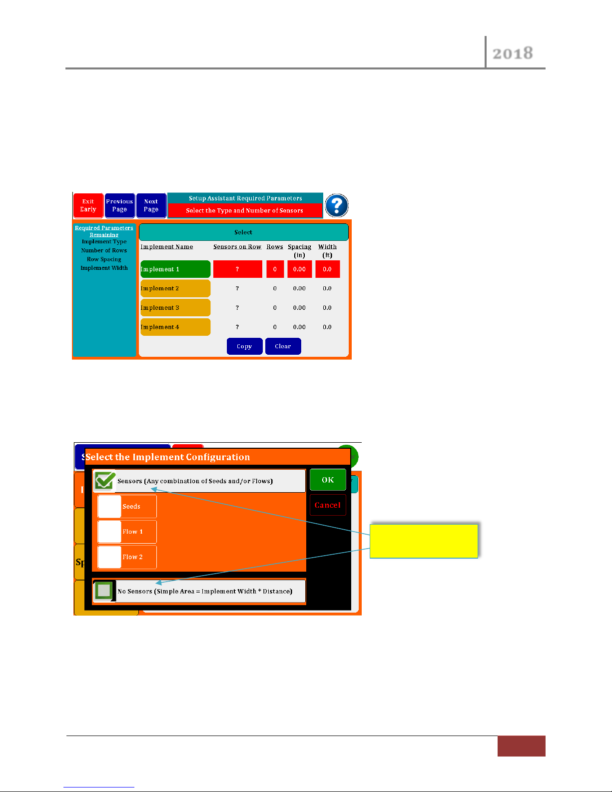
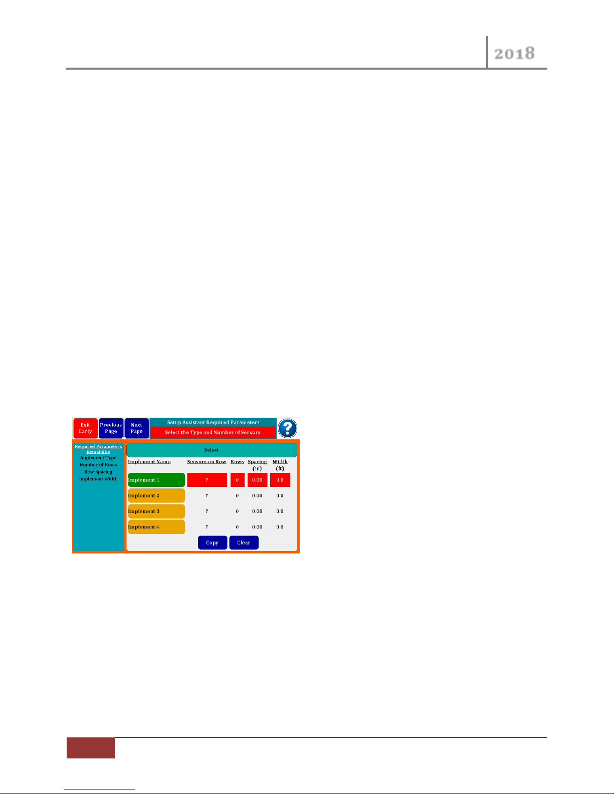
The following screen is our starting page for the Setup Assistant.
Figure 3 Setup Assistant Start Page
2.3.1 Implement Sensor Select
By pressing the Red ? Button in the “Sensors on Row” column, the following dialog box will appear.
Figure 4 Implement Configuration Dialog
You have two options by selecting the “Sensors” check box at the top of the screen you may select your
implement Sensors. The “No Sensor” selection is discussed in the Optional Setup Section.
Page 12

VM-5500 Operator’s Manual
2018
12
Quick Start | Rev 0418.1
Image indicates you
selected Seeds and Flow
2.3.2 Implement Type Select
Use the Check Boxes to select if your monitor is connected to seed sensors, flow meters or both. If you
select Flow 1, you may select Flow 2 as well if you are using two different flow rates on your
system. Keep in mind that you are limited to 16 total sensors on this monitor. Depending on your
selections the monitor will configure itself to ask for only the required parameters.
Figure 5 Implement Configuration with All Sensors
For each Flow you have set, you may selection if there is a Sensor per Row, or only Sensor at the pump
or Master Flow. This Flow selection is independent for each Flow (1/2). In the page above you would
have an Implement with Seeds and Flow 1 with sensors at each row.
Press Ok will return you to the Starter page which will now look like this.
2.3.3 Implement Row, Spacing and Width settings
For the Row, Spacing and Width settings press the appropriate button and a Numeric keypad will pop-
up. Enter your number of Rows first, if you then enter the Spacing your Width will be calculated for you.
If after the Row entry, you enter the Width the Spacing will be calculated for you. You can override the
calculated values if you desire.
Page 13

VM-5500 Operator’s Manual
2018
Rev 0418.1 | Quick Start
13
Green Background indicates that
you are done with this page.
List Changes as you Enter
Parameters.
Figure 6 Row, Spacing and Width Setup
By pressing the Red 0 Button under the Rows column a “Enter Row Spacing” Dialog Box will appear.
Press the Spacing and Width Buttons to open up the Numeric Keypad and enter each parameter.
As you enter each Parameter you will see the List of Require Parameters on the Left change.
Press “Next Page” to go to the Display Assignments Page.
Page 14
VM-5500 Operator’s Manual
2018
14
Quick Start | Rev 0418.1
2.3.4 Display Assignments
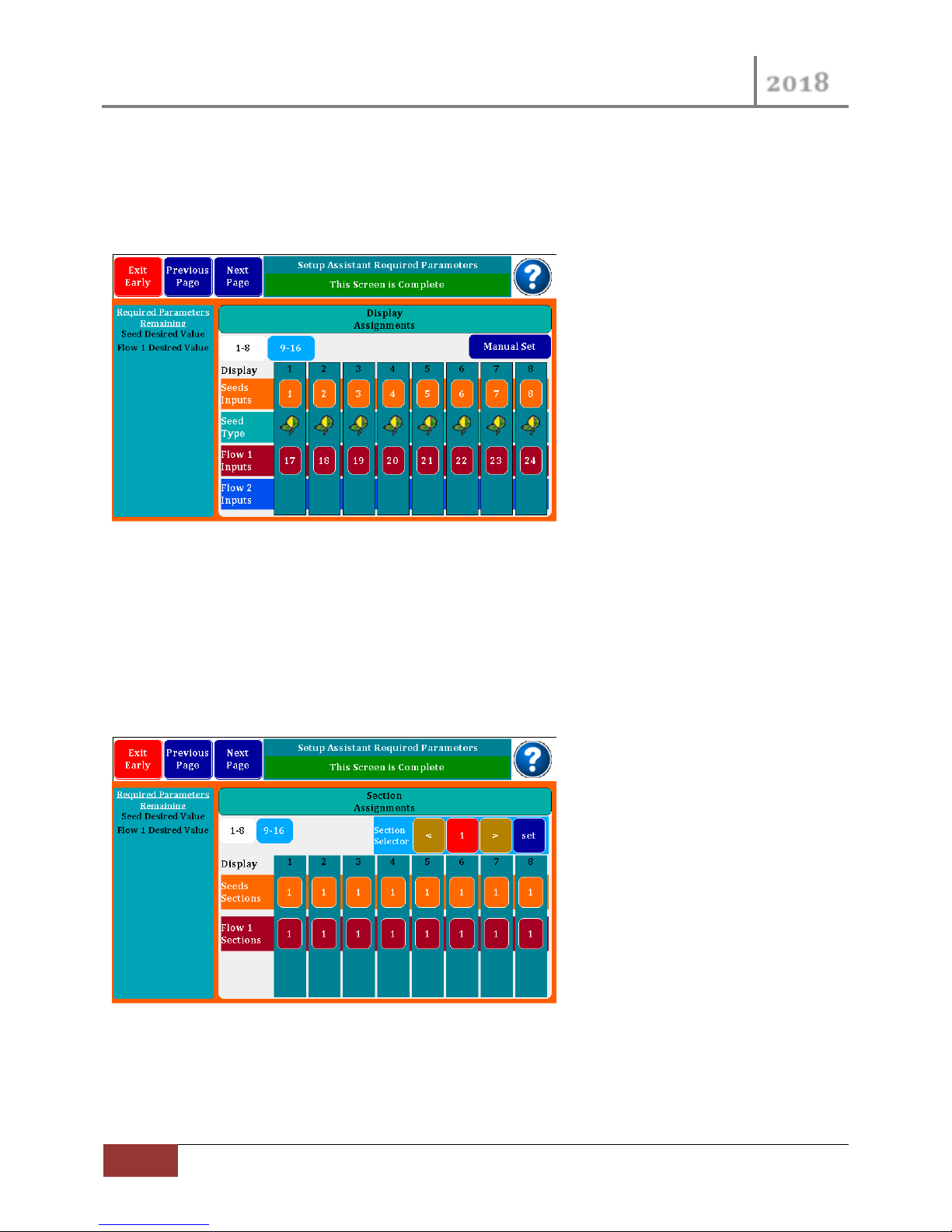
The Display Assignments page is a visual cross reference between the Display Rows and the cable
harness Row wires. Only 8 Display Rows can be seen at 1 time, navigation buttons are available to
navigate to the next set of 8 Rows.
Figure 7 Display Assignments Viewer
The assignments are automatically chosen for you, you can change them to match your implement. If
you need to Change the assignments see Manual Row Assignments in section 3.1.3 below.
2.3.5 Section Assignments
If you have a planter or liquid system that is setup with section shutoff’s, you can configure the rows to
match so the monitor will recognize the shutoffs and not report continuous row failures.
Figure 8 Section Control
By default All Sensors are setup as 1 Section.
If you are not going to use Section Control with your implement, just Press the BLUE “Next Page” button
to navigate to Product Sensor page.
Page 15

VM-5500 Operator’s Manual
2018
Rev 0418.1 | Quick Start
15
2.3.6 Product Sensor “Seeds”
If you had selected Seeds at the start of this Quick Start the following Screen will appear. The Product
Sensors Seed screen is where you can set your Desired target rate for your Seeds/Acre. After you enter
this rate the default Maximum and Minimum Limits will be calculated with +/- 20%. You may change
percentages or enter absolute numbers.
Press and hold Blue entry fields for a pop-up Numeric Keypad.
Figure 9 Product Sensor Setup for Seeds
Press the Desired Rate Button
After you enter the Desired Value you can likewise change the calculated Limits. Notice the Require List
for our example is now down to only one parameter.
At this point you may also adjust the Sensor Gain parameter. The Sensor Gain is a method to adjust the
actual number of seeds being planted to what is being detected by the seed sensor. You can move
Page 16
VM-5500 Operator’s Manual
2018
16
Quick Start | Rev 0418.1
population numbers up or down by percentages. Generally used when drilling soybeans to compensate
for doubles. Suggested beginning number is an increase of 12% for most drills.
If you configured your monitor with Seeds ONLY, at this point the Exit button would have changed to
GREEN and the text would read “Exit Finish”. Before you press any buttons go to Section 2.4.1 for
further instructions.
If you had configured your monitor with FLOW (as in this Quick Start Example), press “Next Page” to
navigate to the next Product Sensor “Flow”.
2.3.7 Product Sensor “Flow”
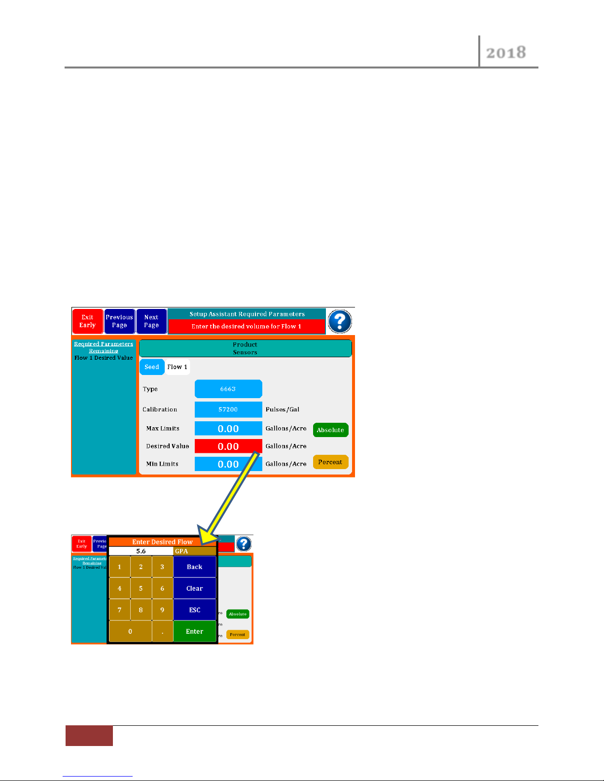
If you had selected 1 or 2 Flows at the beginning of this Quick Start you will need to enter the following.
You must select the flowmeter part number (found on your flowmeters) and then enter the desired GPA
along with the limits. The calibration number is auto generated.
Figure 10 Product Sensor Setup for Flow ½
Press the Desired Rate Button
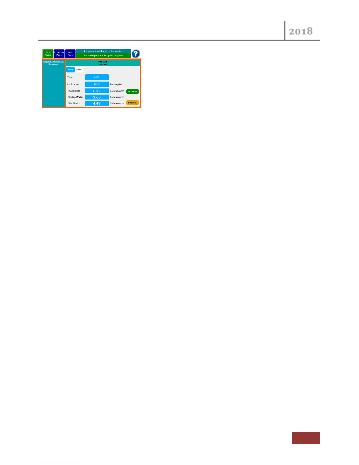
After you enter the Desired Value you can likewise change the calculated Limits. Notice the Require List
for our example is now complete.
Page 17
VM-5500 Operator’s Manual
2018
Rev 0418.1 | Quick Start
17
If you had selected two Flow inputs at the beginning of this Quick Start, you will need to press “Next
Page” again, and enter this same information for Flow 2.
With our example at this point the Exit button would have changed to GREEN and the text would read
“Exit Finish”. Before you press any buttons go to Section 2.4.1 for further instructions.
2.4 Exiting Quick Setup (Setup Assistant)
2.4.1 Exit Finish
At this point all required elements have been entered correctly, the Exit Button is now Green and reads
“Exit Finish”.
Your monitor needs a very accurate measure of Speed to provide proper monitoring of Seed population
and Flow rate. The monitor defaults the Speed input to External Speed (RADAR IN) and has a default
Calibration.
But before you go to the field you need to Exit the Setup Assistant by pressing the “Exit Finish” button
and then proceed to Sections 3.3.4 & 0 below. These Sections are part of the Advanced Setup Assistant;
however you can navigate directly to these Setup Screens after pressing “Exit Finish”. Select your Speed
Input and then perform a Speed Calibration procedure to assure proper speed readings.
You are now done with the Quick Start.
2.4.2 Exit Early
If you need to leave this Quick Start procedure before you are finished, you can do so by pressing the
Exit Button which would be Red if you were exiting early. The monitor will save your present entries and
Exit the Setup Assistant; however you will not be able to go to the field until you come back in and finish
the Quick Start.
2.4.3 Not Finished ???
This Quick Start is complete; however the Setup Assistant can still navigate to other features of the
monitor. The other Features are covered in Section 3.2 below.
Page 18
VM-5500 Operator’s Manual
2018
18
Optional Setup | Rev 0418.1
3 Optional Setup
In this section we will go back to some options that we passed by in the Quick Start Section above, as
some implements require Extra Product Sensor (Section 3.1) configurations.
We will also navigate through setting up Accessory Sensors (Section 3.2) as well as some User Interface
Setup (Section 3.3) parameters.
Section 3.1, 3.2 and 3.3 are additional features and are navigated between just like the Quick Start Basic
Features in the Setup Assistant.
Section 3.4 describes the use of the Setup Screen in NORMAL mode which allows you to navigate
directly to the desired parameter using Tab Buttons, instead of Stepping through them in the Setup
Assistant Mode.
3.1 Extra Product Sensor Configurations
In this section we will reference back to the Quick Start Section where we could have made different
selections and then explain them.
3.1.1 Implement Page Options
In the very first page of the Quick Start Section 2.3 you could have modified additional parameters and
exercised other features.
Our Quick Start Example used the Implement 1 configuration. Your monitor can support 4 different
Implement configurations. The setup assistant can walk you through setting up anyone of the 4
available.
The Implement names default to Implement 1…4, you can change these names to match the name of
your Implement (Corn, Beans, Sprayer 1, Sprayer 2, etc..). Press the Green Implement button for a pop-
up Keyboard to enter the desired text.
The Copy button allows you to Copy a configuration from one of the other three configurations. The
Clear button can clear all configuration information from the selected Implement.
Page 19
VM-5500 Operator’s Manual
2018
Rev 0418.1 | Optional Setup
19
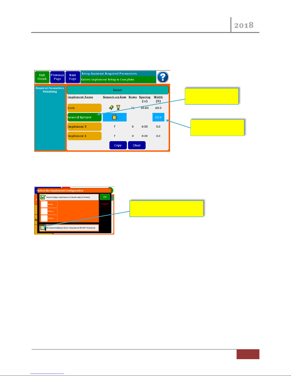
Select “No Sensors”
Enter Name
Enter Width of
Implement
After you have set the Sensors Type, a “Quick Set” button will appear next to the Copy and Clear
Buttons. With this button you can Reset the Default Seed Rows to Harness Row Wires.
3.1.2 Area Monitor Setup
Figure 11 Area Monitor (No Sensors) Setup
In the working Implement in Green called “General Sprayer was configured in the Implement
Configuration Dialog, the “No Sensor” Check Box was checked.
3.1.3 Manual Harness Assignment
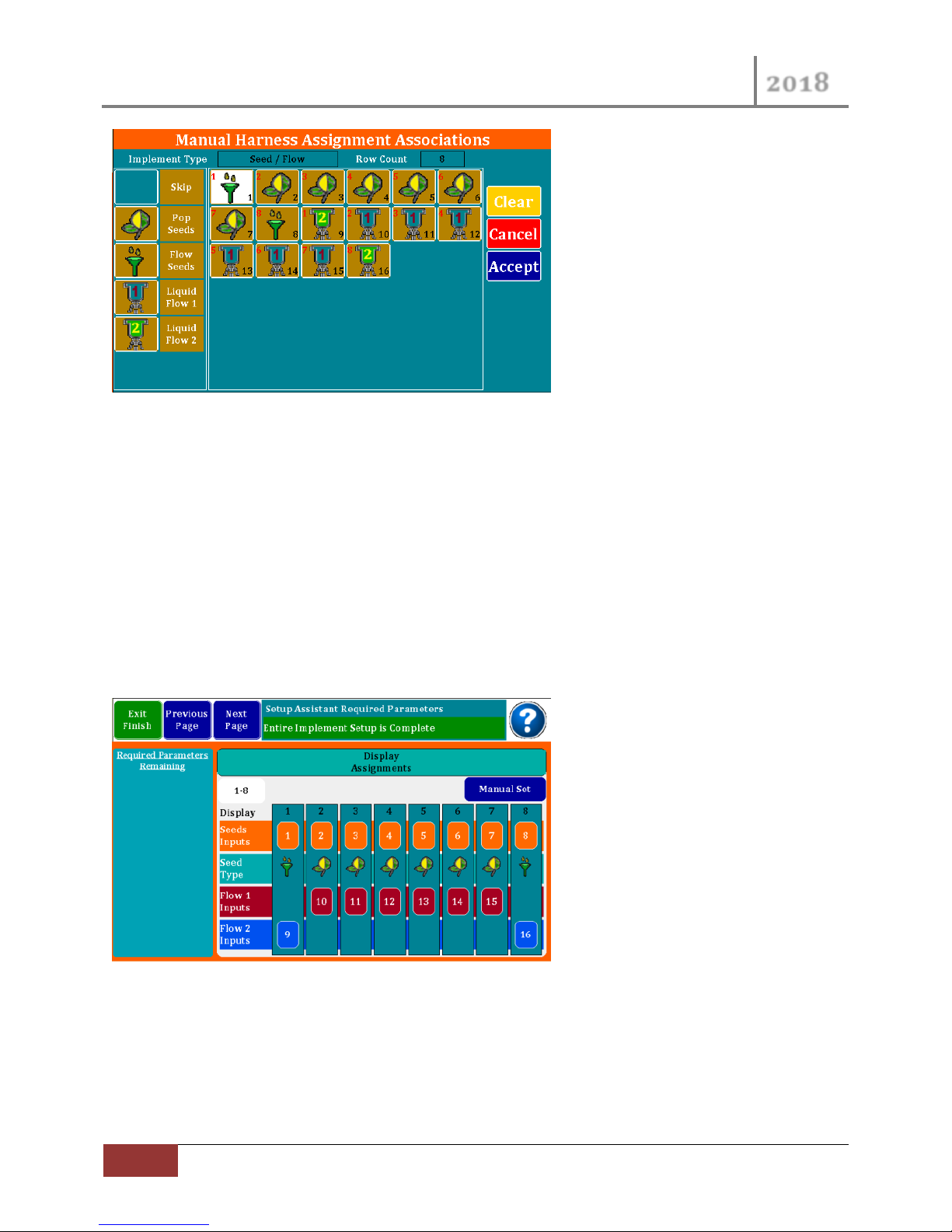
From the Display Assignments Screen (Section 2.3.4 above) you could have pressed the Manual Set
button to pop-up the Manual Display Assignment dialog.
Depending on your Monitor Model you will see differ number of Row inputs. First select a Row button
in the middle section of the page. Then on the left side of the page are your Row assignment options.
Pressing 1 of the Sensors will assign it to the highlighted Row input in the middle. The monitor will
increment to the next Row after each Sensor selection.
Page 20
VM-5500 Operator’s Manual
2018
20
Optional Setup | Rev 0418.1
Figure 12 Manual Harness Assignment Dialog
The figure above shows an 8 Row implement with 8 Rows of Seed, and 8 Rows of Flow. The Flow
sensors are assigned to two different rates. The funnel “Flow Seeds” is for flow blockage sensors often
used on air seeders.
The Black Number in the bottom Right corner of each Row button is the Row Wiring number. The Red
Number in the top Left corner is the Display or Implement Row.
Press “Clear” to start over, “Cancel” to Exiting without recording changes, or “Accept” to accept changes
and return to the Display Assignment Viewer.
With the setup in Figure 12 above the Display Assignment Viewer would look like the following:
Figure 13 Resulting Display Assignments
3.1.4 Section Control
Refer back to Section 2.3.5 above
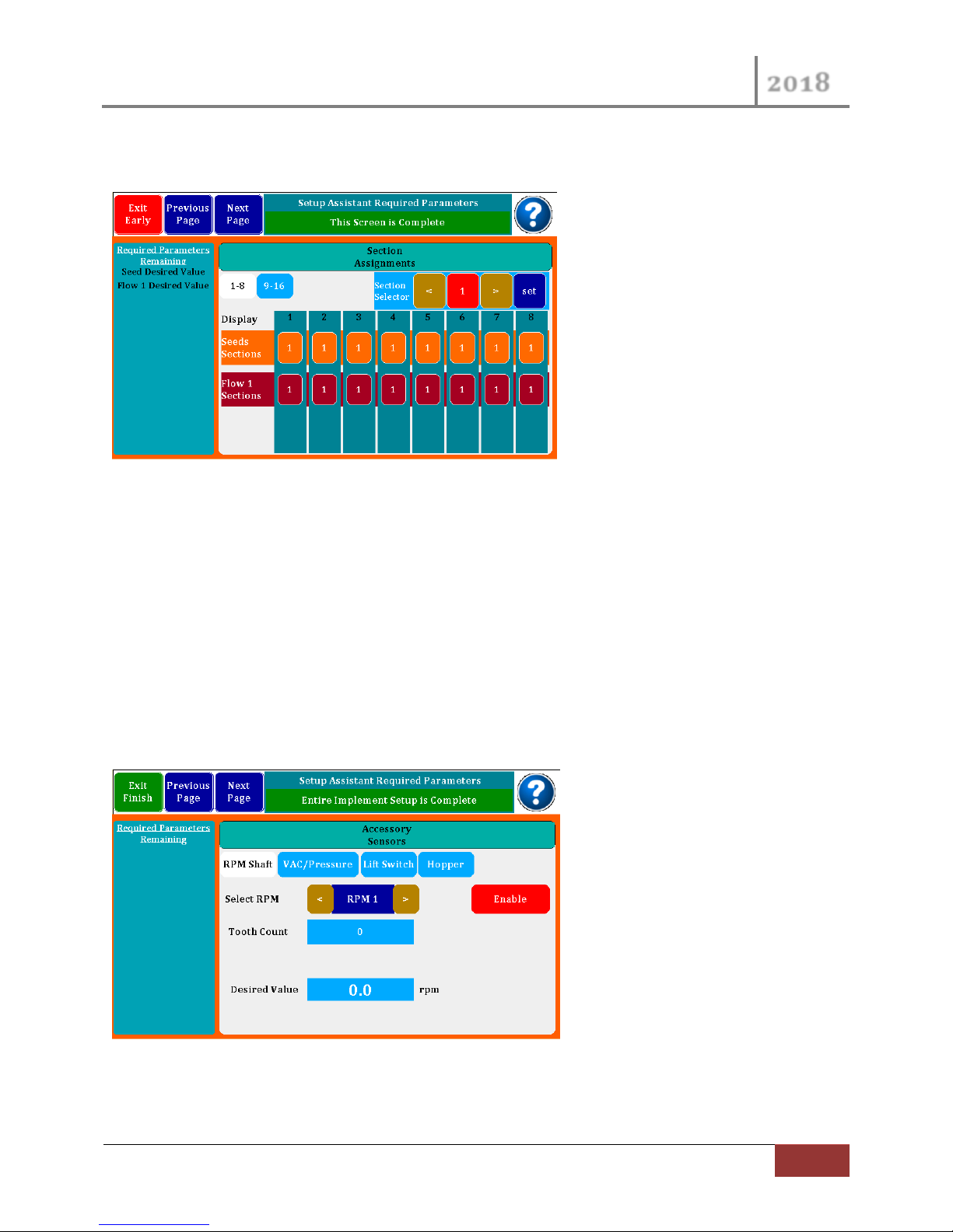
Section assignments may be entered in this screen. If you have a planter or liquid system that is setup
with section shutoff’s, you can configure the rows to match so the monitor will recognize the shutoffs
Page 21
VM-5500 Operator’s Manual
2018
Rev 0418.1 | Optional Setup
21
and not report continuous row failures. Select section number at top, and then touch the row pad to
add it to that section.
Figure 14 Section Control
Press the “<” and “>” arrows to change the Section Sector Number. Press the Section Sector Number for
a few seconds to bring up dialog box to go directly to the Sector Number you desire.
3.2 Accessory Sensors
This section picks up where the Quick Start Section 2 above left off.
If you have RPM, VAC/Pressure, Lift Switch or Hopper Level sensors, you will need to scroll to those
setups where you will enter the required information similar to what you have done in seed and flow
sensor setup.
Figure 15 Accessory Sensors
Page 22
VM-5500 Operator’s Manual
2018
22
Optional Setup | Rev 0418.1
3.2.1 RPM Shaft
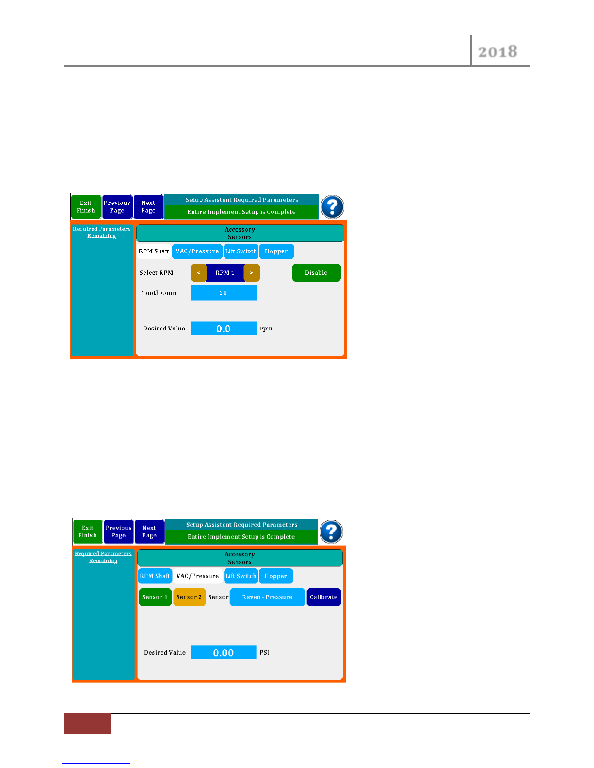
In the First Accessory Sensor Screen above you start with the RPM Shaft Sub Page.
You have the ability to setup two RPM sensors. Select the which RPM sensor with the left and right
arrow buttons.
Enable the Sensor by pressing the Red “Enable” button.
Figure 16 RPM Sensor Setup
Enter the Tooth Count for 1 revolution RPM Wheel, then enter the Desired Value for the RPM Sensor
just as you did in the Product Sensors (including Max and Min Limits when they show up).
3.2.2 VAC/Pressure Sensor Setup
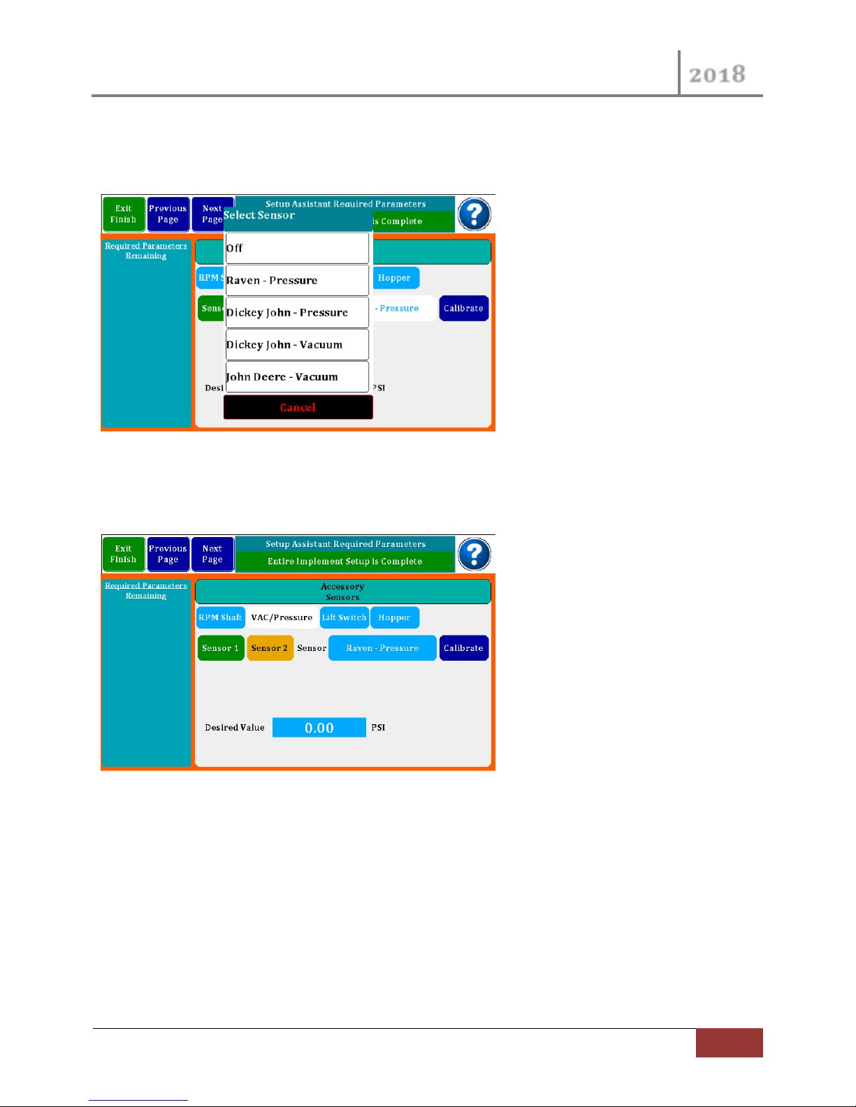
VAC/Pressure setup, you may setup 2 sensors as either VAC or Pressure sensors. Depending on your
selection the setup screen will modify itself to ask for associated information.
Figure 17 VAC / Pressure Setup Screen
Page 23
VM-5500 Operator’s Manual
2018
Rev 0418.1 | Optional Setup
23
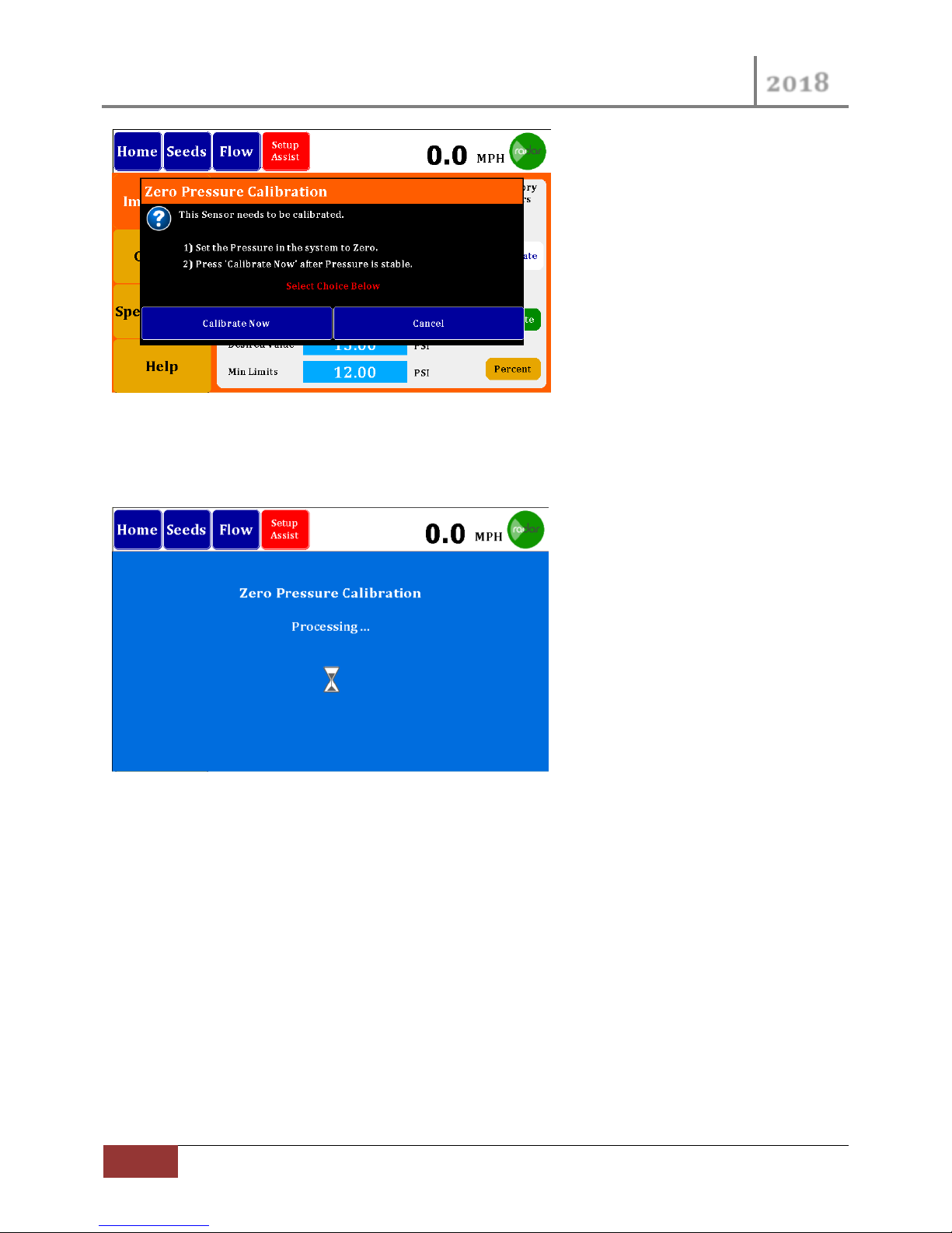
To select the desired Sensor type Press on the Sensor Selection button. This button will provide a
selection dialog box as follows. The list includes Off, Raven – Pressure, Dickey John – Pressure, Dickey
John – Vacuum and John Deere – Vacuum.
Figure 18 VAC / Pressure Sensor Select
After you Select your Sensor, you will again have to Enter the Desired Values just as you did for the RPM
and Product Sensors.
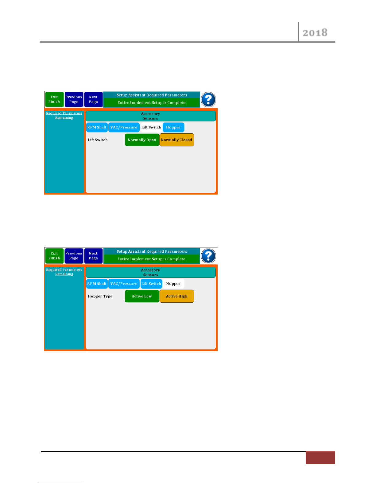
The Raven- Pressure Sensor requires a calibration. You may press the “Calibrate” purple button to
calibration your sensor. When you do this the following screen will provide you with more steps.
Page 24
VM-5500 Operator’s Manual
2018
24
Optional Setup | Rev 0418.1
Figure 19 Zero Pressure Calibration Start
If you Press the “Calibrate Now” button the system will show the following screen while it performs the
Calibrate function.
Figure 20 Zero Press Calibration Processing
Page 25
VM-5500 Operator’s Manual
2018
Rev 0418.1 | Optional Setup
25
3.2.3 Lift Switch Configuration
The Lift switch may now be configured to be Normally Open or Normally Closed to accommodate
different lift switches.
Figure 21 Lift Switch Setup Screen
3.2.4 Hopper Type Sensor Setup
The Hopper Input Type may now be configured as an Active Low or Active High Hopper Sensors.
Figure 22 Hopper Setup Screen
Page 26
VM-5500 Operator’s Manual
2018
26
Optional Setup | Rev 0418.1
3.3 User Interface Setup
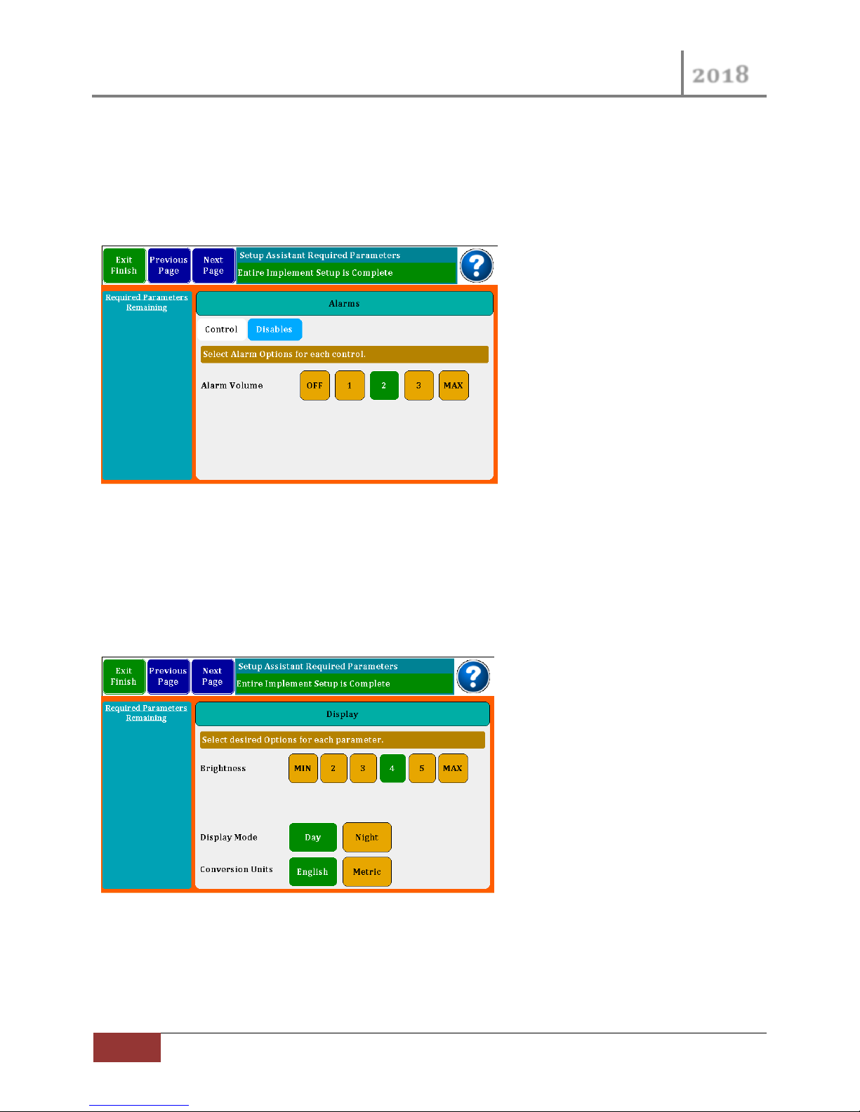
3.3.1 Alarm Setup
In this screen you may set the volume of the Alarm or Turn the Sound Off for all. In the Disables tab you
can change the Enable state of each accessory sensors.
Figure 23 Alarm Setup
Press “Next Page” to navigate to the Display Settings page.
3.3.2 Display Settings
The Display setup is where the screen brightness and Day/Night Mode are set. Conversion units may be
set to English or Metric.
Figure 24 Display Settings
Press “Next Page” to navigate to the Misc. Settings page.
Page 27
VM-5500 Operator’s Manual
2018
Rev 0418.1 | Optional Setup
27
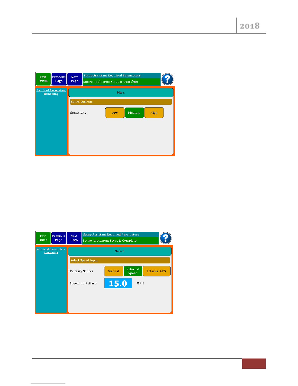
3.3.3 Misc. Settings
Sensitivity is the amount of averaging time used to calculate rates. The longer times may show more
accuracy, but changes will come less often. This is normally set to Low or Medium.
Figure 25 Misc. Settings
Press “Next Page” to navigate to the Speed Setup page.
3.3.4 Speed Setup
The Speed Input screen is where you select what will be your primary source of speed. You can select
Manual where you enter a number for the speed you are driving; Radar is used when an external Radar
or GPS device is plugged into the 4 pin port on the back of the monitor. The third choice is the Internal
GPS when enabled. Speed Input Alarms may be set for over speed.
Figure 26 Speed Setup
Press “Next Page” to navigate to the Speed Setup page.
Page 28
VM-5500 Operator’s Manual
2018
28
Optional Setup | Rev 0418.1
3.3.5 Speed Calibration
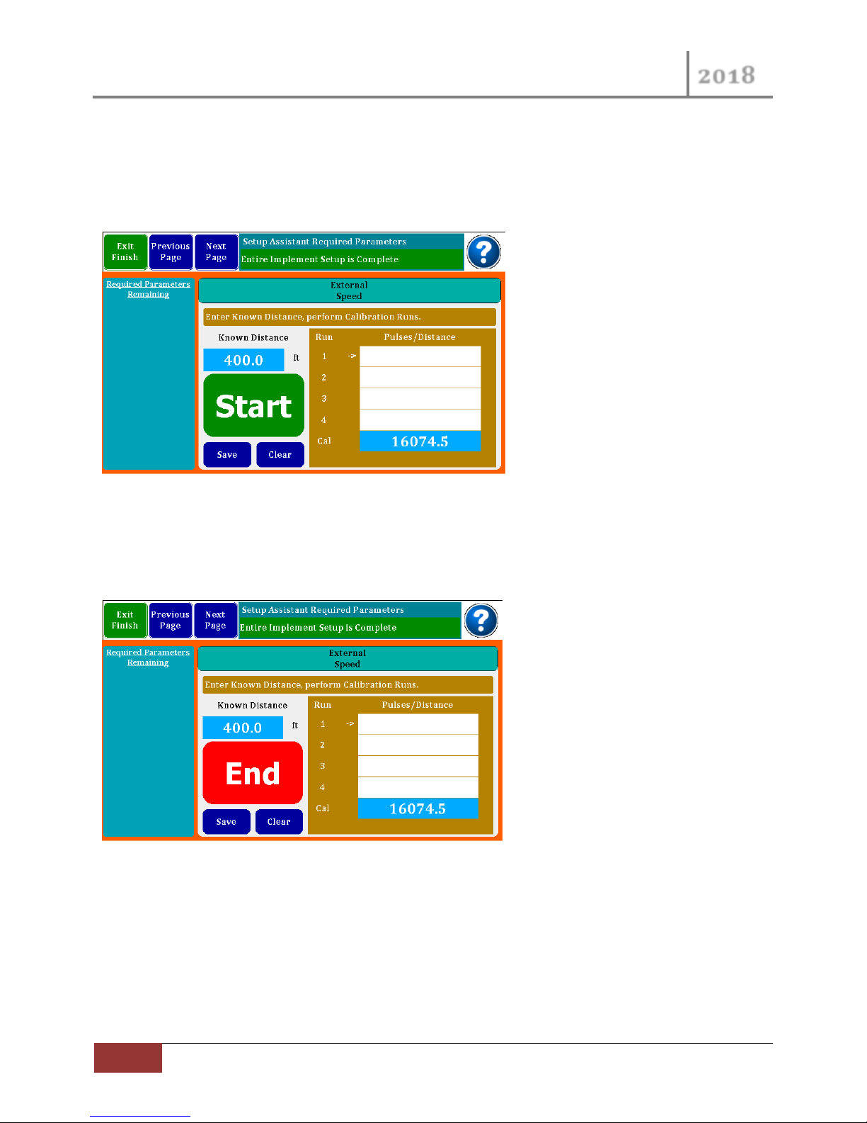
When using an external Radar or GPS, you will need to calibrate the device. This is done by driving a 400
foot course. It is suggested that you do 4 runs and the monitor will store and average them for you.
Flag your course and as you pass the first flag, press Start.
Figure 27 Speed Calibration
When you pass the second flag, press End. A calibration number will appear in the Run # box. Continue
to do three more runs to get an accurate number. The monitor will average the numbers and press
Save to keep the calibration number. Speed derived by this calibration will be quite accurate.
Figure 28 Speed Calibration "End"
Press “Next Page” to navigate to the About and Assistance pages.
Page 29
VM-5500 Operator’s Manual
2018
Rev 0418.1 | Optional Setup
29
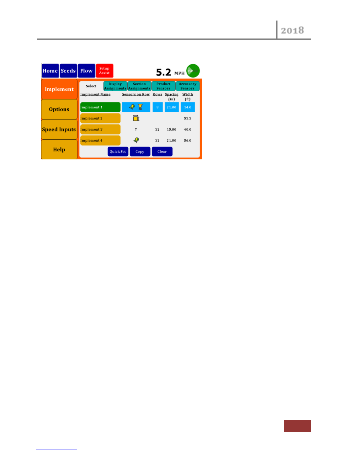
3.4 Setup Screen
Figure 29 Setup Screen
The Setup Screen can be moded as a step through Assistant just as it has since the start of this manual.
You may also navigate directly in Normal mode. All setup attributes are available by selecting the
appropriate Vertical and Horizontal tabs.
When in Normal Setup Screen the buttons on the left navigate you to different functional areas. Then
within each Functional Area additional horizontal Tab Buttons will appear across the Top allowing you to
navigate further in to detailed features.
Page 30

VM-5500 Operator’s Manual
2018
30
Monitor Operation Screens | Rev 0418.1
Name
Available
Description
Snap Shot
Home
Any Sensor
The Home screen provides a
graphical view of the Row data
as well as selectable summary
information.
Showing Seed and Flow data.
Seed Dashboard
Seed Sensor
Summary information for seeds
as well as other Accessory
Sensors.
Acre Counters are also available.
Flow Dashboard
Flow Sensor
Summary information for flow
sensors as well as other
Accessory Sensors.
Acre Counters and Field
Counters are also available.
Singulation
Seed Sensors
The Singulation data is available
for all Seed sensors.
Area Counter
No Sensors
If no Sensors are available the
monitor can be turned into a
simple Acre counter, using
measured distance and a user
entered Width of implement.
4 Monitor Operation Screens
The Monitor has 6 different Operation Screens. Depending on your Implement Setup, some screens
may or may not be accessible.
Page 31
VM-5500 Operator’s Manual
2018
Rev 0418.1 | Monitor Operation Screens
31
In Home Screen
In Flow Dash
Radar Speed
Alarm Messages
Manual Speed
Adjustments
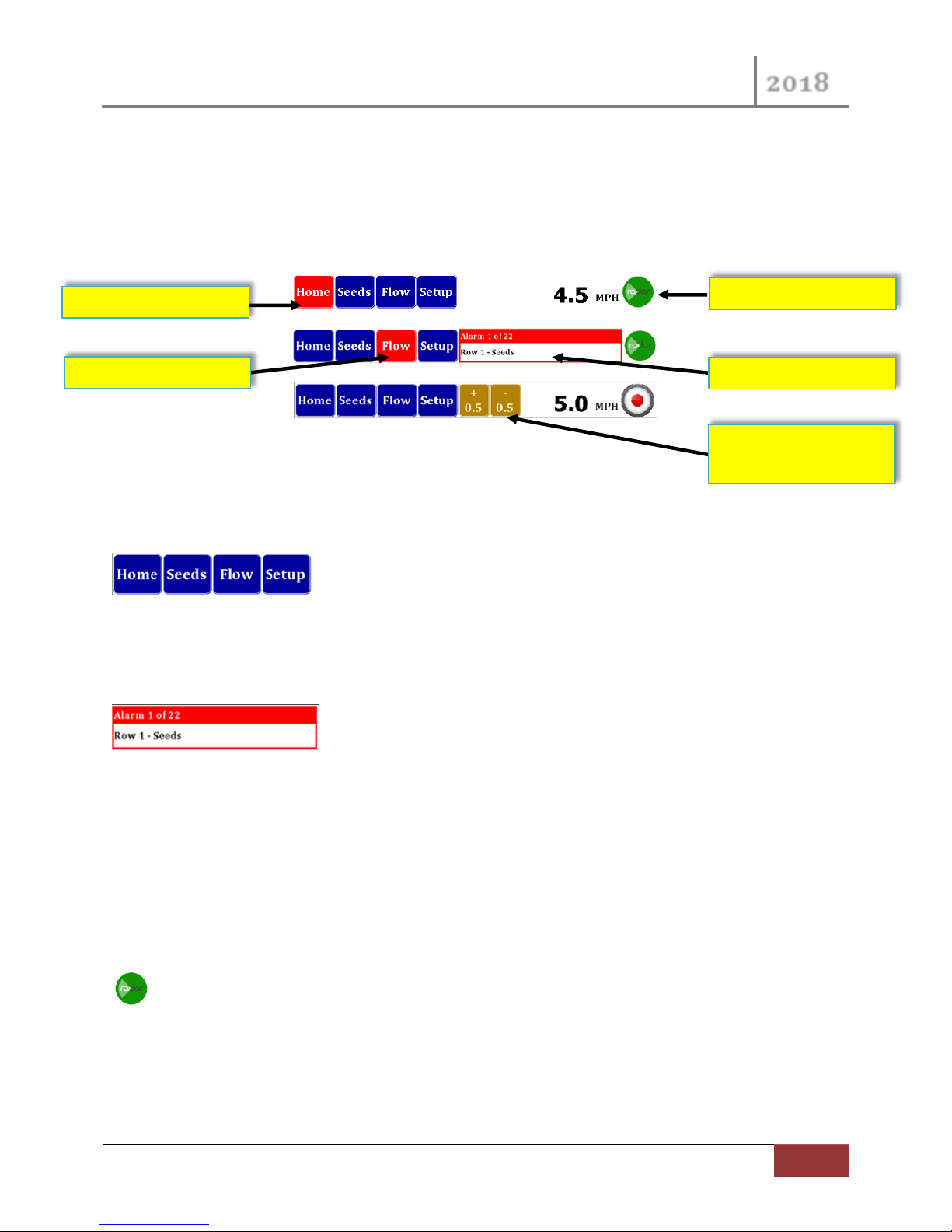
4.1 Menu Bar
The Menu Bar provides a way to navigate to all of the Operational Screens, as well as providing status
information.
The Menu Bar resides at the Top of the Monitor display and is always visible.
4.1.1 Screen Navigation
All you to navigate to different screens, buttons are display if screen is
available. Button names can change indicating alternate features. Selected screen is denoted by the
button changing color to Red.
4.1.2 Alarm Message Area
This area shows Alarm messages. If multiple messages are available, the
monitor will cycle through them, until alarm goes away or are temporarily suspended.
If Alarm messages are present you may acknowledge All of the present messages by pressing on the
message area. The Audible alarm associated with the PRESENT alarms will stop sounding and the
message center will be cleared. If new Alarms are set, they will be shown in the message center again.
This temporary acknowledgement of the Alarms is cleared after an All Rows Fail or lift switch is
activated.
4.1.3 Speed Icon
The Speed Icon on the far right indicates the type of Speed Input you have selected. This selection
can change via the Setup Screens or directly by pressing the Icon itself and making a selection.
Page 32
VM-5500 Operator’s Manual
2018
32
Monitor Operation Screens | Rev 0418.1
Console Area
Bar Graph Area
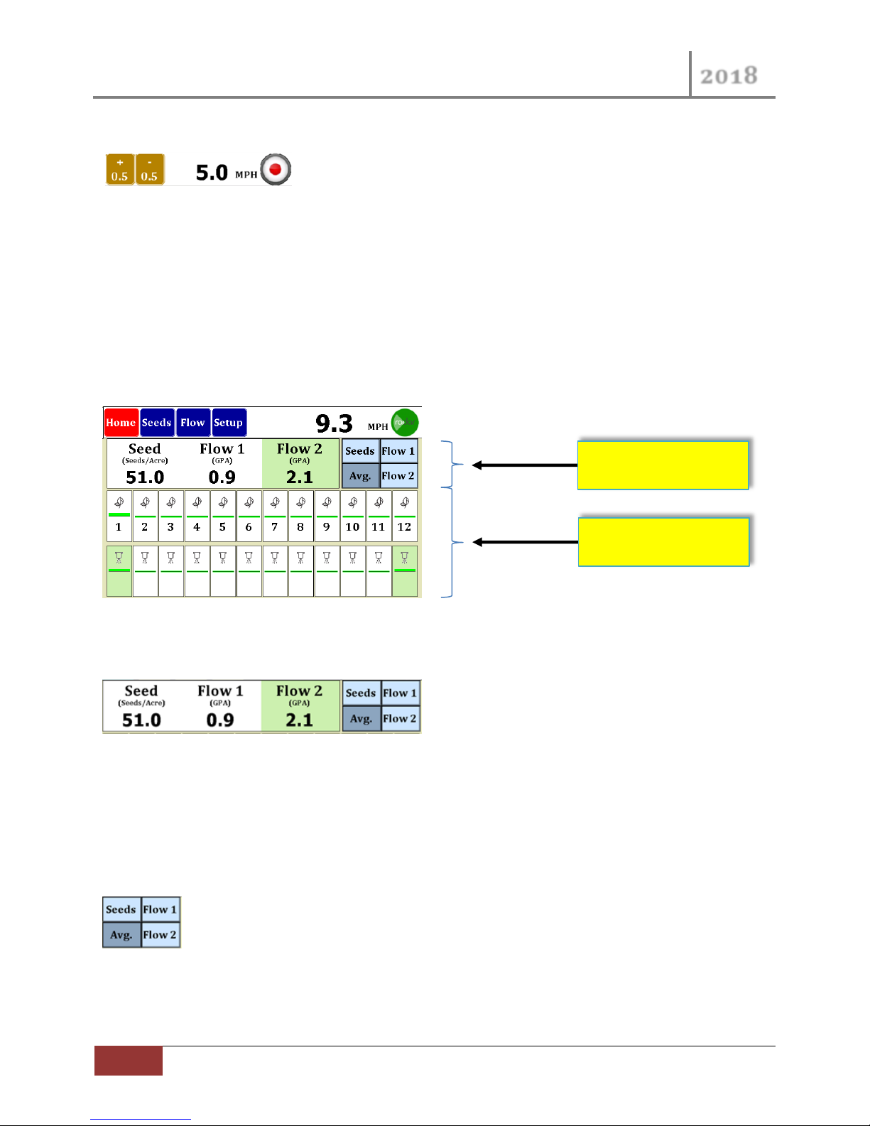
4.1.4 Manual Speed
If Manual Speed is selected the Icon on the Right will look like this Circle
with a Red Dot. Two additional Buttons will be provided, which allows a quick way of adjusting the
speed up or down by 0.5 mph. You may also select your speed by pressing the Speed number, a pop-up
Numeric Keypad will come up for you to enter your speed.
4.2 Home Screen
The Home Screen provides a Row by Row indication of Product Sensors performance in the Bar Graph
Area. The Console Area provides Average summary data, Min / Max or Numeric Present data values.
Figure 30 Home Screen Layout
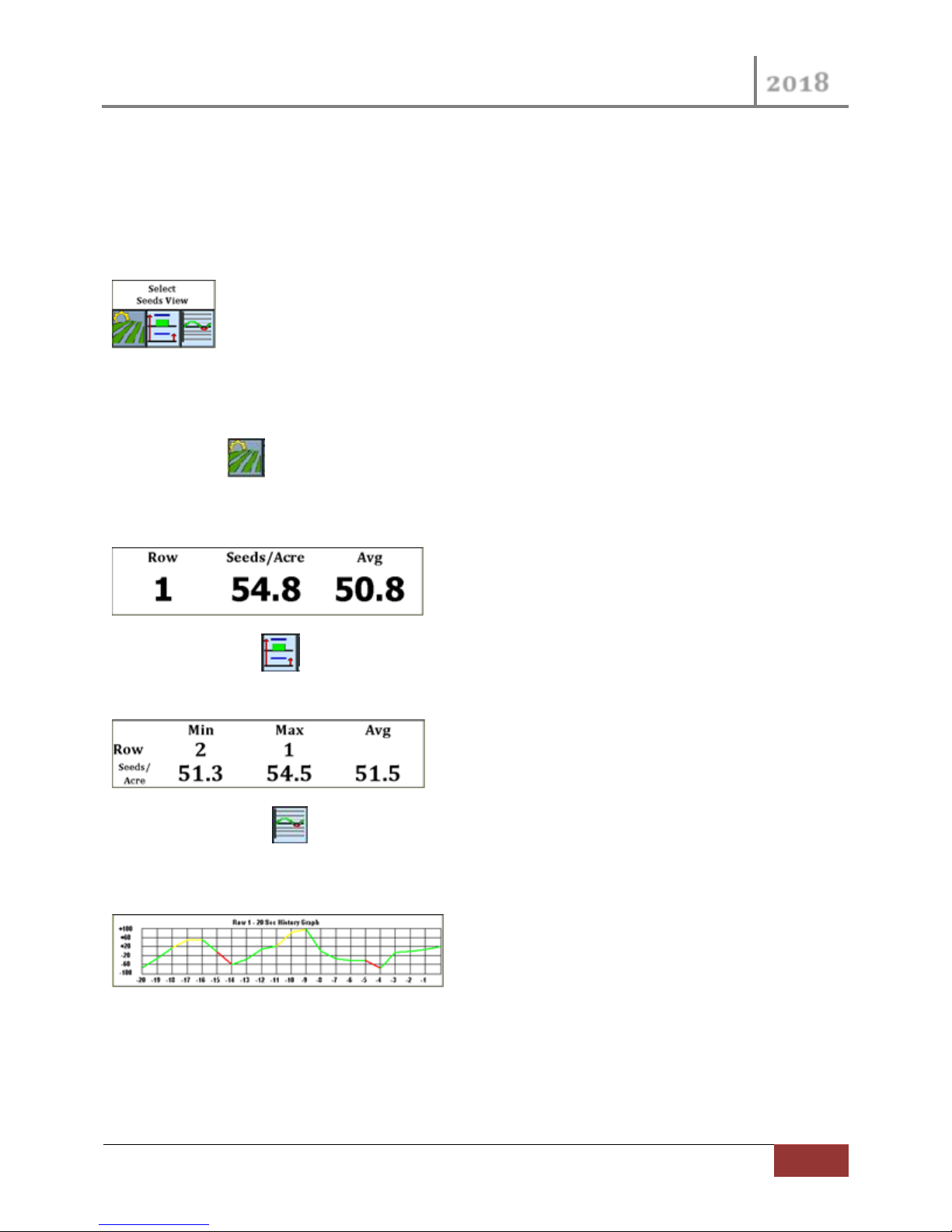
4.2.1 Console Area
Figure 31 Home Console Area
The Console Area can be moded to provide many pieces of data. The Green Background will always
indicate FLOW 2 in this Console as well as the Bar Graph Areas.
If multiple Product Sensors are selected (Seeds\Flow, Flow1\Flow2, etc…) the right side of the console
area will contain Sensor Selection buttons.
Figure 32 Home Console Sensor Select
By pressing the “Avg.” button, the Console will provide Average Data for each Sensor as in Figure 31
Home Console Area above.
Page 33
VM-5500 Operator’s Manual
2018
Rev 0418.1 | Monitor Operation Screens
33
By pressing 1 of the other available Product Sensor the Console Area will change to providing specific
information on that Product Sensor. The Sensor Selection buttons will also be replaced with Individual
Parameter selections buttons, these selections will disappear in time if nothing is selected.
If only 1 Product Sensor is selected for the working Implement, the Individual Parameter Selection
Buttons will be continuously displayed.
Figure 33 Individual Parameter Selection
Three different Console Area Views are selectable by the Individual Parameter Selection buttons.
The Row Button provides details about 1 Product Sensor. You can change the Selected Product
Sensor by pressing the desired Bar Graph indicator. You can go directly to this View mode at any time
by pressing the Bar Graph indicator.
The Max/Min Button provides present Min Max and Average for the Selected Product Sensor type.
The Max and Min values also provide Display Row number for each value.
The Line Graph Button provides a Line Graph of the last 20 seconds of the active Product Sensor.
The Line Color correlates to the Bar Graph colors which indicate above/below and within the Desired
Limits for the Product Sensor.
Page 34
VM-5500 Operator’s Manual
2018
34
Monitor Operation Screens | Rev 0418.1
Seed Exceeding Upper
Limit, Alarm Silenced
Seed Exceeding Upper
Sounding
Flow 1 Below Lower
Sounding
Flow 2 Below Lower
Sounding
Seed Flow within
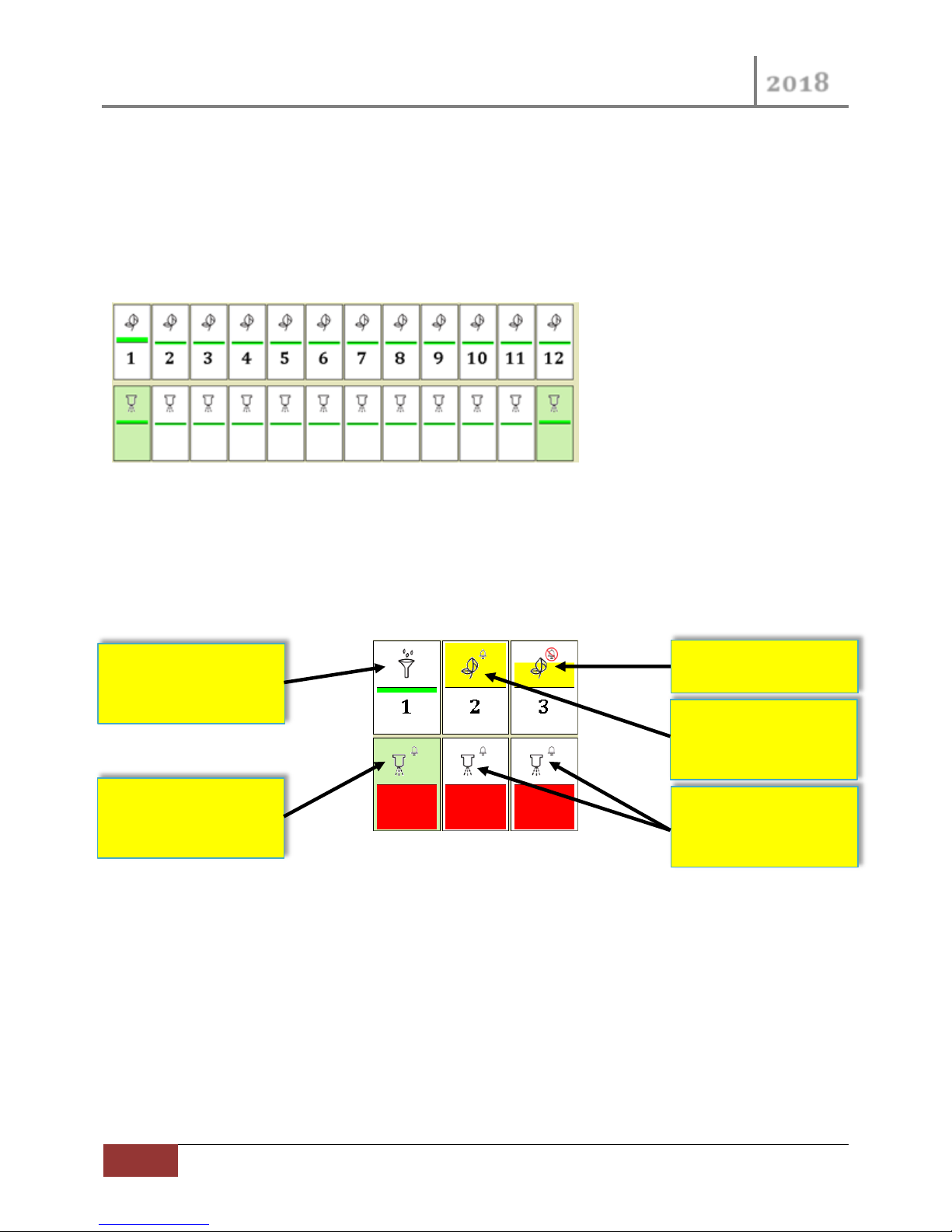
4.2.2 Bar Graph Area
The Bar Graph Area provides individual indicators of Product Sensor readings. The center vertical line
represents the Desired Value for that Product. The Bar Graph will be filled in for readings above and
below the Desired Value. Green Bars indicate the Reading is within the Limits. If the Reading goes below
the Lower Limit the color will change to RED. If the Reading goes above the Upper Limit the color will
change to YELLOW.
Figure 34 Home Bar Graph Area
The Individual Bars contain other identifying and status graphics. The Number represents the
Implement Row, if there are multiple Sensors per Row, the Number will be only display on the top Bars.
The Icons indicate the type of Product Sensors (Pop Seed or Flow Seed or Flow or Master Flow). The
Green Background is an indication of FLOW 2 readings.
Limits
Limit, Audio Alarm
Limit, Audio Alarm
Figure 35 Bar Graph Examples
To Turn OFF the Audible Alarm for an individual Product Sensor Press and Hold a Bar Graph Indicator for
3 seconds, the Alarm indicator will change to an Alarm with a red circle and cross out. Press and Hold
again to remove the disable. These disables will be remembered through “All Rows Fail” or “Lift Switch
Active” conditions. The two ways to remove the disable is Press and Hold as just described or Turn OFF
the monitor.
Limit, Audio Alarm
Page 35
VM-5500 Operator’s Manual
2018
Rev 0418.1 | Monitor Operation Screens
35
4.3 Seed Dash Board
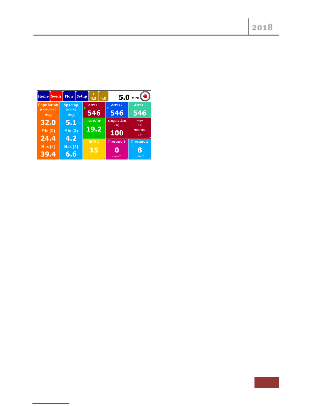
The Seed Dash Board provides summary information for seeds as well as other Accessory Sensors. Acre
Counters are also available.
The Seed Dash is only available is the selected Implement includes Seed Product Sensors.
Figure 36 Seed Dash Board
4.3.1 Population and Spacing
The Population provides Average, Min and Max values from instantaneous analysis of all Seed Sensors.
The Implement Row is also displayed for the Max and Min values.
The Spacing for the seeds has the same analysis as for the Population values.
4.3.2 Acre Counters
Three independent Acre Counter can be Stop/Run or Cleared, the latest Counter will be save through
power cycles of the Monitor. The counters are based of Width of Implement and Distance. The Green
Arrow on a Counter indicates that it is in the Run Mode. A Red Square indicates that the Counter is in
Stop Mode.
To Change the Mode or Reset a counter, press and hold the counter Tile. After a few seconds two
buttons will appear on the Tile. The Left button will allow you to toggle the Mode between Stop and
Run. The Right button can be pushed to Reset the counter (note the Reset occurs immediately, no
verification requested).
4.3.3 Acre/Hr and Singulation
The Acre/Hr Tile provides an instantaneous indication of Acres per Hour.
The Singulation indications of Skips, Multiples and Singulation always add up to 100%. These values are
based on the analysis of ALL Seed Sensors.
To see Singulation per individual Seed Rows, navigate to the Singulation Screen by press and hold of the
double wide Tile. See Section 4.5 Singulation Screen below for details.
Page 36
VM-5500 Operator’s Manual
2018
36
Monitor Operation Screens | Rev 0418.1
4.3.4 Accessory Sensor Tiles
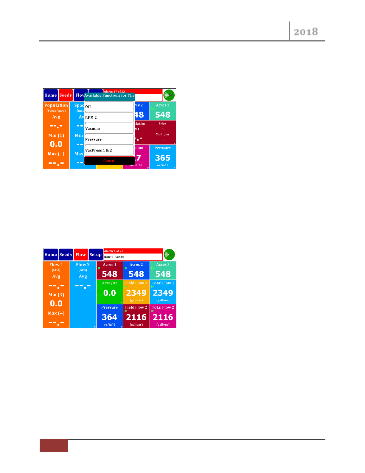
The Accessory Sensor Tiles across the bottom left tiles can be assigned per your desires. These Tiles
have a peel indicator in the bottom right corner of the Tile, this indicates optional values.
Figure 37 Seed Dash Optional Tiles
By a Press and Hold on these Tiles a Selection Dialog will appear with All Accessory Sensors that you
have enabled within the Setup for your active Implement. These selections will be remember through
power cycles of the monitor. VacPress 1 & 2 is a selection that would toggle the Tile between the two
sensors, changing the Tile every few seconds.
4.4 Flow Dash Board
Figure 38 Flow Dash Board
The Flow Dash Screen is similar to the seeds screen. Shown at left is the Flow Rate. It will Show GPA
Average, Minimum (Row Number) and Maximum (Row Number). If you have two Flows selected, there
will be a second column for Flow 2.
Across the top you will find the acre counters. There are three acre counter memories in the system and
they may be started, stopped or reset by holding the button down for three seconds to bring up a
Start/Stop and Reset button. Shown above, a triangle shows acres counting, whereas a square indicates
counter has stopped.
Page 37
VM-5500 Operator’s Manual
2018
Rev 0418.1 | Monitor Operation Screens
37
Center right shows Acre/Hour rate followed by a calculated Field Flow 1 and Total Flow 1. Both of these
may be started/stopped or cleared by holding the button down for three seconds.
On the bottom row you will see the current average GPM flow rate (This will toggle between Flow 1 and
Flow 2 if you have both) and finally, you have Field Flow 2 and Total Flow 2 which may be
started/stopped or cleared by holding the button down for three seconds.
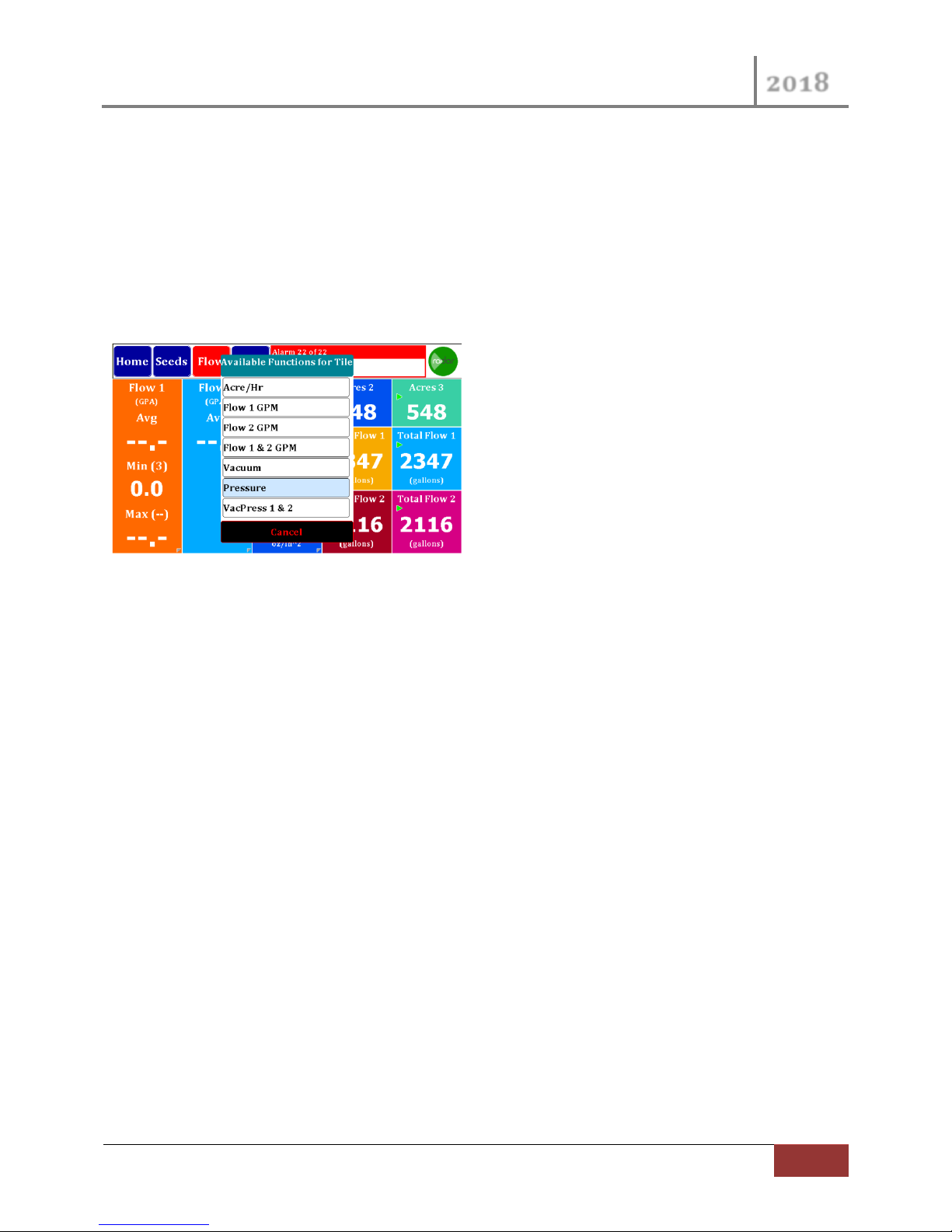
The center lower 2 tiles can be configured with existing Acres/Hr, Flow GPM and the new Pressure or
Vac sensor values. Simply press on the Tiles and a dialog box will appear with possible Tile Assignments.
Figure 39 Flow Dash Optional Tiles
4.5 Singulation Screen
The Singulation Screen provides row by row Singulation conditions. To enter this screen navigate to the
Seed Dashboard and press on the Singulation cell, you will be taken to the Row Singulation screen.
After entering the screen you will have a view very similar to the Home Screen. The screen has a
console or statistics area, a view select area and a graphical area. The view select area lets you chose
from 3 different console statistics, Row Select, Max Value, and Overall average. The Row Select shows
the Singulation, Skips and Double of the selected row, these values represent a percentage singulation.
Press on the Row Graphical area to select which Row to view. The Max Value shows the Row number
and Max value in percent of Skips and Multiples. The Row count value is a count of all rows that are
exhibiting Skips and Multiples. The Overall Average view contains the values normal scene on the Seed
Dashboard screen.
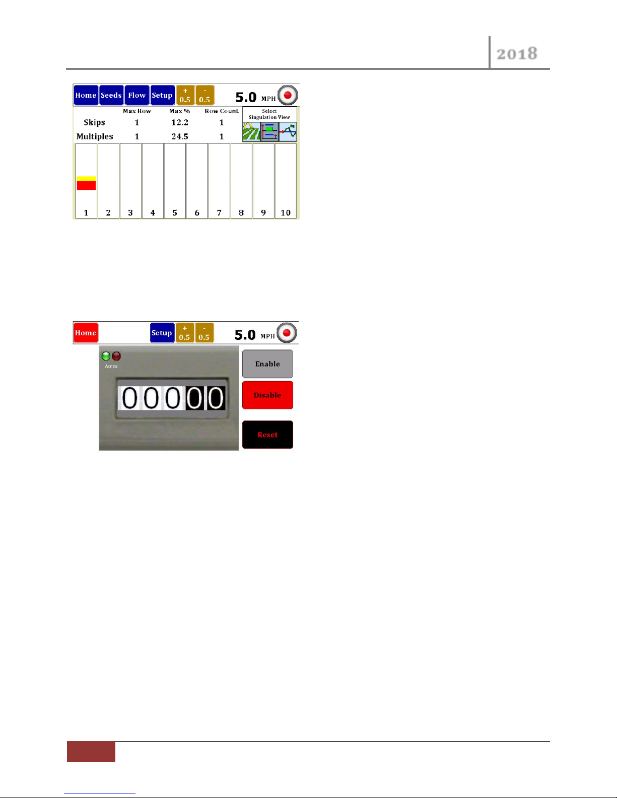
For each row graphical object you can see the present Skips and Multiple percentages. Skips are shown
in yellow above the center line and Multiples are shown in Red below the center line. If neither of these
colors show for a given Row this would indicate 100 % singulation.
Page 38
VM-5500 Operator’s Manual
2018
38
Monitor Operation Screens | Rev 0418.1
Figure 40 Singulation Screen
The screen shot above shows 12.2% Skips on Row 1 as shown in yellow. The Multiples are at 24.5 and
are shown in Red.
4.6 Area Monitor
Figure 41 Speed/Area Monitor Screen
Speed/Area Mode provides a very simple screen that calculates the acres covered. This count can be
Started or Stopped with the Enable/Disable buttons. You may also reset the Acre count at any time.
Selection and Configuration of this mode is very similar to selection and configuration of other
Seed/Flow implements. In the Setup Screen select an Implement then press on the associated Sensors
on Row Icon area. This will bring up the new “Select the Implement Configuration” dialog box. In this
dialog select the check box at the bottom, the check box text is “No Sensors”.
Page 39
VM-5500 Operator’s Manual
2018
Rev 0418.1 | Monitor Operation Screens
39
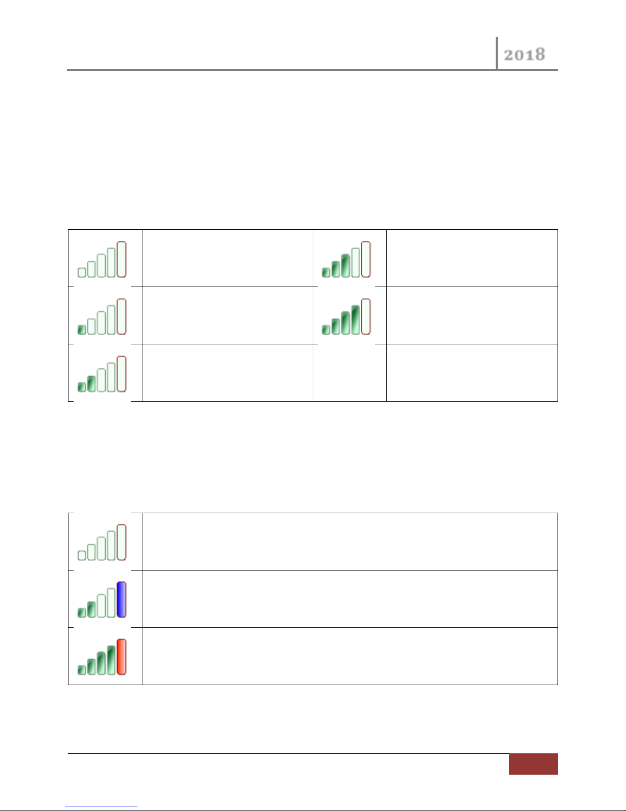
Zero Satellites
7 to 9 Satellites
1 to 3 Satellites
10 or more Satellites
4 to 6 Satellites
The far right indicator is blank or clear which means the GPS does not have a lock on any
satellites.
In this condition the GPS cannot determine the location, therefore Speed cannot be
determined.
The far right indicator is blue which means the GPS has a Lock on the satellites.
In this condition the GPS can determine the location, and therefore Speed can be
determined.
The far right indicator is red which means the GPS has a WAAS Lock on the satellites.
In this condition the GPS can determine the location, and therefore Speed can be
determined. The WAAS lock provides the GPS solution with the highest accuracy.
Internal GPS Status Appendix A
The Internal GPS status is provided in the ICON located in the upper right corner of the monitor display.
This upper right corner area is described more fully in the MPH INDICATOR section on page 19.
The GPS ICON indicates the Signal Strength and GPS Lock Status. The ICON is made up of 5 bars, the left
4 bars indicate the Signal Strength and the tall bar on the far right indicates the GPS Lock Status.
The Signal Strength is a measure of how many Satellites are being tracked by the GPS sensor. The
following table explains the 5 possible Signal Strength conditions:
Figure 42 Satellite Signal Strength
The GPS Lock status is indicated by the color of the far right status bar. This status is truly independent
of the other 4 Satellite Strength status bars, however there is a correlation between them. To establish
a GPS lock the GPS sensor must be tracking several satellites, to establish a GPS WAAS lock the GPS
sensor typically requires even more satellites. The following table provides the GPS Lock Status
indicators with typical Satellite Strengths:
Figure 43 GPS Lock Status
Page 40

VM-5500 Operator’s Manual
2018
40
Monitor Operation Screens | Rev 0418.1
Flow Meters Appendix B
Flow Meter Installation B.1
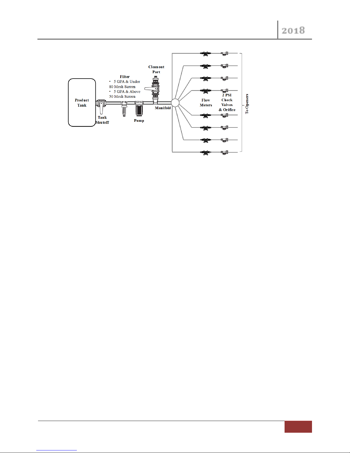
A plumbing diagram for a typical system used on a planter for the pop up/side by side fertilizer has
been included. Starting with the product tank that is normally mounted on the planter frame each of the
components used in the system will be discussed regarding their function and installation.
#1 Leading out of the tank a main shutoff valve should be in place to cut product flow to the entire
system.
#2 The next component on the diagram is a filter which is critical for keeping foreign material out of the
pumping system that would cause plugs or blockages to occur. It is recommended for an application rate
of 5 gallons per acre or less to use an 80 mesh filter screen. Application rates higher than 5 gallons per
acre can be applied with a 50 mesh screen filter. A finer screen is used at lower application rates to keep
the small flow meters from plugging. The filter should be placed before the pump to allow for proper
filtering of the fertilizer being applied.
#3 The pump is the next item in line after the filter. There are many types of pumps that are commonly
used for liquid fertilizer application. Piston, squeeze, hydraulic and 12V DC type pumps have all been
used with this system. All these pumps work well as long as they are properly sized for the specific
application rate that is being applied.
#4 After the pump a cleanout port is shown that would be used for rinsing out the system after the
season is over. It may also be used for rinsing if you are going to be out of the field and will not be using
the system for an extended period of time. The cleanout port will also be useful in flushing out the
system if blockages should occur due to contamination problems in the fertilizer system. The clean out
port consists of a valve and a garden hose adapter for hooking up the rinsing system.
#5 Following the cleanout port is the distribution manifold followed by the individual row flow meters.
The flow meters can be grouped together after the manifold or distributed on the bar individually closer
to each opener.
#6 An optional bracket (Part No. 6675) is available for purchase that holds up to 8 flow meters. This will
help keep track of which flow meter is going to which row plus it helps in making a neat, safe, and
organized installation of the flow meters. Each precision flow meter is made with 2 sizes of hose barbs
on each end of the flow meter housing. These barbs are ¼” and 3/8” which makes adapting to your
planter plumbing system easy.
#7 After the flow meters a check valve/orifice plate assembly is recommended. A 2 psi check valve
works well for most systems. The lines will stay filled with liquid and leakage on the ends will be
prevented when the unit is raised. Properly sized orifice plates will make the application rate accurate
and consistent from row to row.
Page 41
VM-5500 Operator’s Manual
2018
Rev 0418.1 | Monitor Operation Screens
41
Figure 44 Pluming Diagram
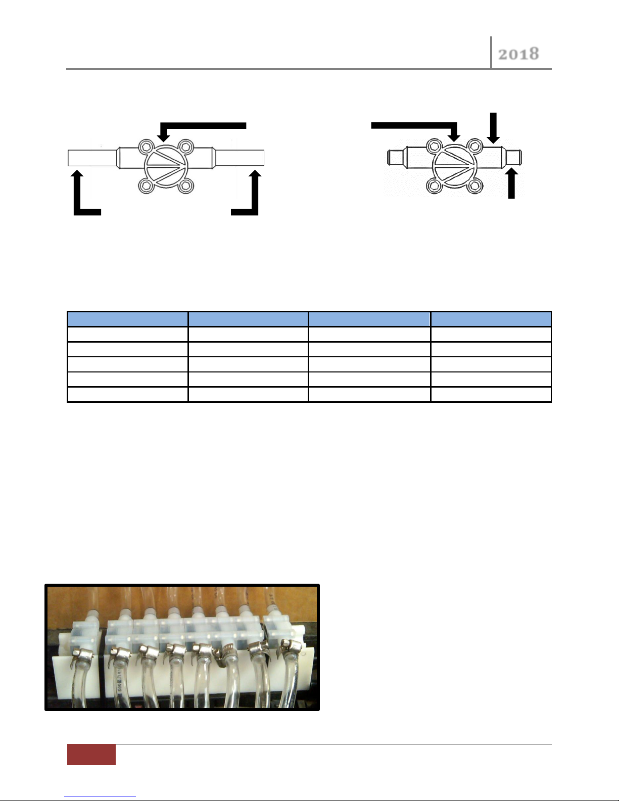
There are some important items to observe when getting ready to install the precision flow meters in
the system. On both the inlet and outlet end of the flow meter, there are two different sized hose
barbs. The smaller is designed to use ¼” ID hose, and the larger barb closer to the center of the meter is
designed to accept 3/8” ID hose. The first step in installing the flow meters is determining which barb
will work best to adapt to the size and type of plumbing on the planter/applicator. The flow meters are
supplied with two 2” pieces of ¼” tubing plus 2 clamps. The tubing is provided as a way to easily
transition to the existing plumbing. If the planter/applicator uses 3/8” hose in the system, you can
simply slide it on and clamp it to the flow meter on the larger barb.
Also available are flowmeters designed to use John Guest fittings. They are manufactured with 3/8”
push on fittings making any necessary maintenance very quick and easy to do. The same specifications
apply to the flowmeters using either type of connections, the Hose Barb or John Guest fittings. To order
the correct flowmeters, use the part numbers on page 26 and include a HB or JG after the number,
depending on the style that you prefer.
Another important feature of the flow meter is a direction arrow showing how material should flow
through the meter. It is made into the housing on the opposite side of where the cable goes into the
meter. It is very critical that the flow meters are installed following this direction of flow indicator.
Inaccurate or inconsistent readings will occur if they are installed backward.
Page 42
VM-5500 Operator’s Manual
2018
42
Monitor Operation Screens | Rev 0418.1
Part Number
GPM Range
Pulses Per/Gallon
Gal/ Per Acre approx.
6663
.013 - .132
57200
2 - 4
6664
.032 - .400
24500
5 - 15
6667
.053 – 1.189
12550
13 - 20
6665
.08 - 2.65
4350
16 - 70
6668
1.32-3.96
3136
50-120
Flow Direction
⅜” Hose Barb
¼” Hose Barb
⅜” Male John Guest
Please note on the cable close to the harness connector the tag that shows the part number for the flow
meter you have. There are 5 different flow meters offered, and they all look the same from the outside.
Each precision flow meter has different operating range so it is important that they be chosen correctly
for your application. Below is a chart showing the operating specifications of each flow meter.
Table 1 Flow Meter Specifications
The Visu FloTM METERS can be installed anywhere between the distribution manifold and the Check
Valve/orifice assembly. The main things to take into consideration are the safety and ease of access to
the flow meters. The flow meter must be installed into each row so the most logical place to mount the
meters would be in a grouping close to the output of the manifold. A bracket (P/N 6675) is available to
hold 8 flow meters in a 9” space. All the fertilizer lines can be ran neat & orderly from the manifold to
the flow meter and from the flow meter to the row. This will also make the wiring harness less complex
as the length of wire required to hook the flow meters up will not be very long and all the connections
will be in one location close to this grouping.
This is an example of an 8 Row System Using
Hose Barb style flowmeters
On a Bracket PN: 6675
Page 43
VM-5500 Operator’s Manual
2018
Rev 0418.1 | Monitor Operation Screens
43
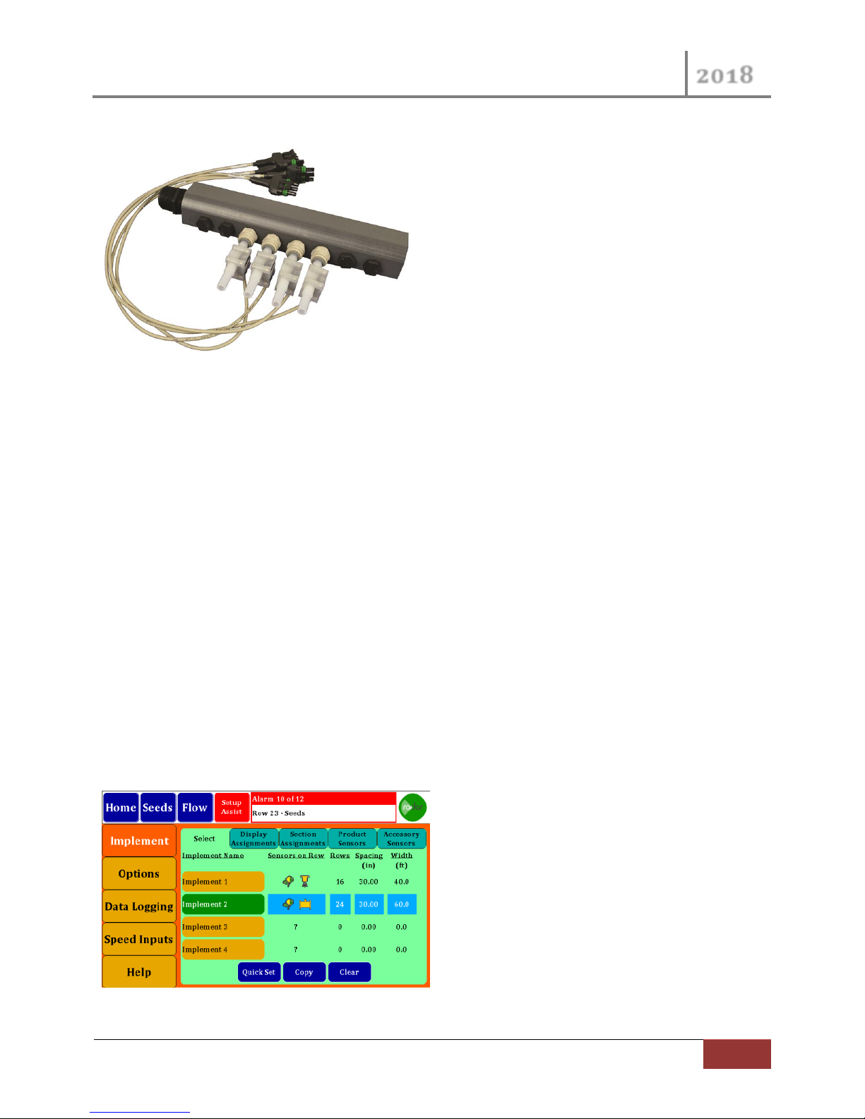
Figure 45 Flow Manifold
This is an example of a 4 Row System
Using John Guest style flowmeters
With our Manifold and Bracket Kit.
8 Row Manifold Kit PN: 6698-8
4 Row Manifold Kit PN: 6698-4
It is also recommend that once you have commenced planting and the lines and the flow meters have
been filled with fertilizer that they remain fully charged until finished planting for the season. This will
help insure that crusting/plugging does not occur and that the flow meter turbine will remain free once
planting begins again. This is the reason we want the check valves installed in the system as this will
insure the lines stay fully charged once the pumping stops. If – for example planting is delayed due to
rain the check valves will insure that the lines remain fully charged and you will not be required to flush
out the system. PLEASE NOTE: One exception to this rule is if you have micro nutrients mixed in with
your fertilizer and the planter is going to be setting for more than a couple of days flushing of the system
is recommended as the ingredients may settle and may cause problems once planting starts again. Once
again if you have made plans for flushing of the system and planting is delayed we would recommend,
you go ahead and flush the system to insure no problems will occur on startup.
Master Flow B.2
This Flow Sensor configuration would replace Nozzle flows Sensors on each Planter Row with 1 Master
Flow Sensor for 1 Product for the entire planter. A Master Flow Sensor can be selected for Flow 1 and /
or Flow 2. This Master Flow sensor is indicated with an Inline sensor icon as seen in the following image.
Figure 46 Monitor Implement Type Selection
Page 44
VM-5500 Operator’s Manual
2018
44
Monitor Operation Screens | Rev 0418.1
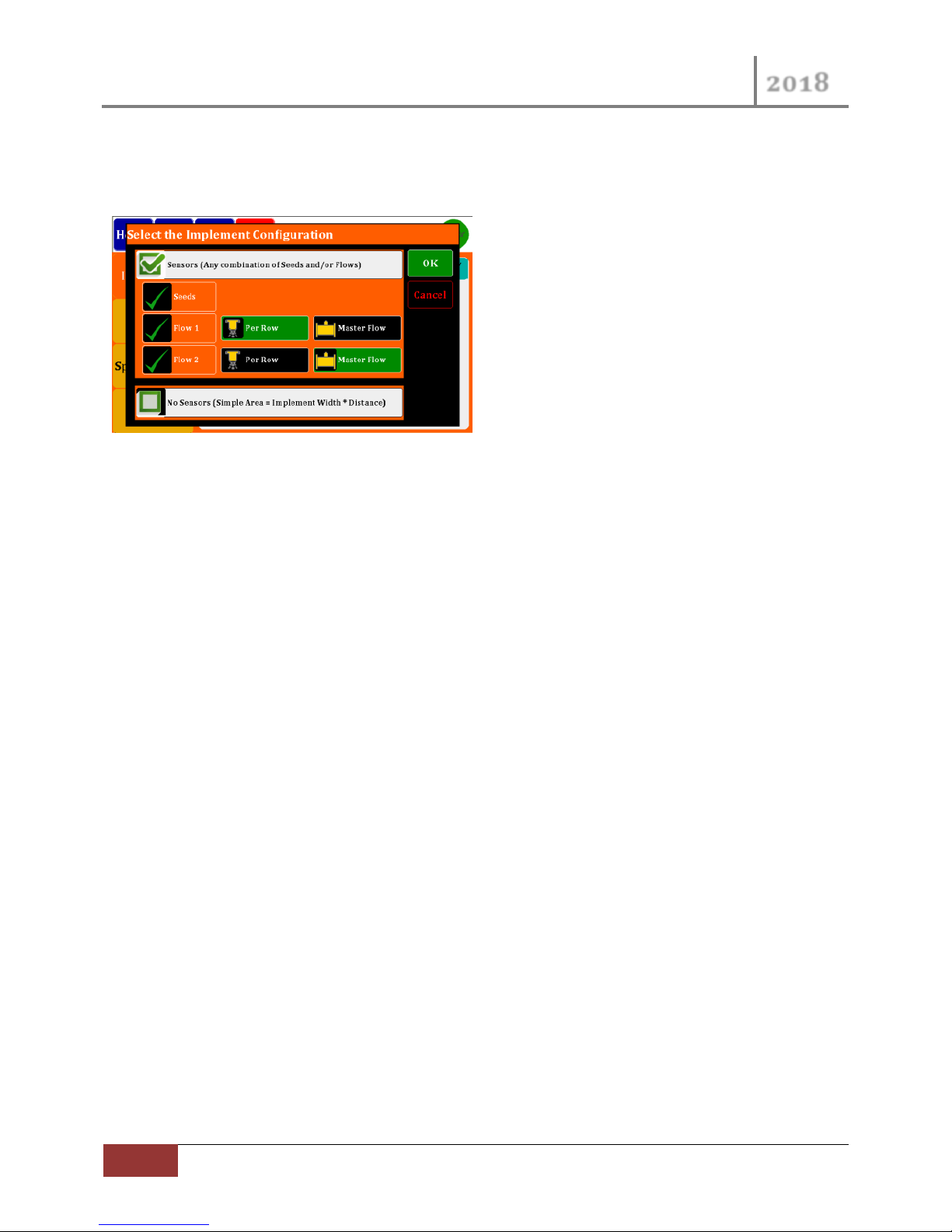
To accommodate configuring of the Master Flow sensor a Implement Configuration screen was
developed. In this screen you can select Flow type for each flow setup. The flow type would be the
normal Per Row of the Master Flow sensor.
Figure 47 Monitor Implement Configuration
The Master Flow indicator on the Home screen represents the entire product applied to the Implement
and therefore will appear differently than normal Row based products. The Display Assignments screen
will also show the Master Flow Icon if selected.
Master Flow Meter calibration number is read in pulses per gallon. This calibration number is typically
displayed on the flow meter with a tag. Raven flow meters output in pulses per 10 gallon, resulting in
the calibration number needing converted Ex: 710/10 = 71 pulses per gallon.
Post Season Storage for the Vanguard Visu-FloTM Flow Meters B.3
Within 2 to 3 days of finishing for the season we strongly recommend a total cleansing of the system
with water. You will need to clean and rinse the fertilizer residue out of the system adequately so it will
not cause issues on start up for the next season. The more thorough job you do now will pay you
dividends as the amount of fertilizer left in system will cause potential sources for blockages next time
the system is used.
Once you have rinsed the system clean you will need to winterize your system. It is recommended that a
good quality RV antifreeze, rated to – 50, is utilized so that freezing will not occur and cause major
damage and avoidable expense to your system components.
Simply run enough RV Antifreeze through your system to replace the water that was used to rinse your
system. Be extra conscientious to FLUSH any area that may trap the water (low spots etc). Make sure
you use enough RV Antifreeze to completely fill your system components with the antifreeze.
Page 45
VM-5500 Operator’s Manual
2018
Rev 0418.1 | Monitor Operation Screens
45
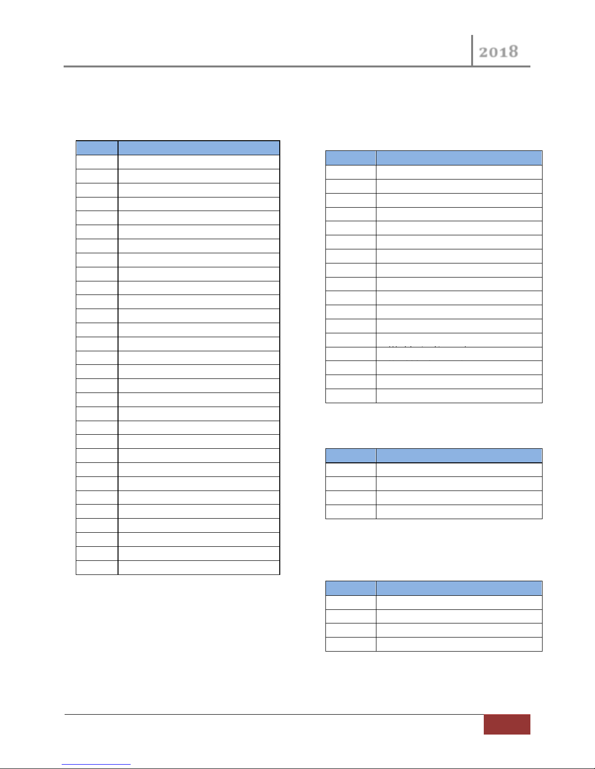
Pin #
Description
A1
Row 1 (green)
A2
Row 2 (white)
A3
Row 3 (brown)
B1
Row 4 (blue)
B2
Row 5 (orange)
B3
Row 6 (yellow)
C1
Row 7 (purple)
C2
Row 8 (gray)
C3
Row 9 (pink)
D1
Row 10 (tan)
D2
Row 11 (white/black)
D3
Row 12 (red/black)
E1
Row 13 (green/black)
E2
Row 14 (orange/black)
E3
Row 15 (blue/black)
F1
Row 16 (black/white)
F2
No Connection
F3
No Connection
G1
No Connection
G2
No Connection
G3
No Connection
H1
No Connection
H2
No Connection
H3
No Connection
J1
Vac 1 analog input (purple)
J2
Vac 2 analog input (gray)
J3
No Connection
K1
Lift Switch Signal (green/bk/red)
K2
8 V Sensor Power (red)
K3
8 V sensor Ground (black)
Pin #
Description
A1
No Connection
A2
No Connection
A3
No Connection
B1
No Connection
B2
No Connection
B3
No Connection
C1
No Connection
C2
No Connection
C3
RPM 1 (brown)
D1
RPM 2 (blue)
D2
VAC 1 frequency input (orange)
D3
VAC 2 frequency input (yellow)
E1
Hopper Level 1 Signal (green)
E2
Hopper Level 2 Signal (white)
E3 - F1
No Connection
F2
8 V Sensor Power (red)
F3
8 V Sensor Power (black)
Pin #
Description
1
12 VDC IN (red)
2
-12VDC IN (black)
3
Visual Alarm Out (rd/wh)
4
Visual Alarm Return (bk/wh)
Pin #
Description
1
Ground (black)
2
Signal (green)
3
12 v. Power (red)
4
Sense (white)
VM5500 Console Pinouts Appendix C
30 Pin Console Pinout C.1
18 Pin Console Pinout C.2
4 Pin Power In/ Alarm Out Pinout C.3
4 Pin Bottom Speed In Pinout C.4
(Radar/Speed)
Page 46
VM-5500 Operator’s Manual
2018
46
Monitor Operation Screens | Rev 0418.1
Pin #
Description
1
Row 1 (green)
2
Row 2 (white)
3
Row 3 (brown)
4
Row 4 (blue)
5
Row 5 (orange)
6
Row 6 (yellow)
7
Row 7 (purple)
8
Row 8 (gray)
9
Row 9 (pink)
10
Row 10 (tan)
11
Row 11 (white/black)
12
Row 12 (red/black)
13
Row 13 (green/black)
14
Row 14 (orange/black)
15
Row 15 (blue/black)
16
Row 16 (black/white)
17
No Connection
18
No Connection
19
No Connection
20
No Connection
21
Hopper Level 1 (green/white)
22
Hopper Level 2 (blue/white)
23
No Connection
24
8 V Sensor Power (red)
25
8 V Sensor Power (red/black/white)
26
8 V Sensor Ground (black)
27
8 V Sensor Ground (white/black/red)
28
No Connection
29
No Connection
30
No Connection
31
VAC 1 analog input (black/red)
32
VAC 2 analog input (white/red)
33
RPM 1 (orange/red)
34
RPM 2 (blue/red)
35
VAC 1 frequency input (red/green)
36
VAC 2 frequency input (orange/green)
37
Lift Switch Signal (red/white)
VM-5500 Implement Pinouts Appendix D
37 Pin Harness Pinout D.1
Page 47
VM-5500 Operator’s Manual
2018
Rev 0418.1 | Monitor Operation Screens
47
Description
Part Number
VM-5500 Console Only
647550
RAM Ball Mount
RAM-238U
RAM Arm and Base Kit (Optional)
647141
647142
647143
Fuse, AGC 5A (Pkg. of 12)
PR050
Visual Alarm (Optional)
647105
Hopper Level Sensor
46682-0270S3
Lift Switch
46372-0150S1
Description
Part Number
Planters
4-row harness
3204A
6-row harness
3206A
8-row harness
3208A
12-row harness
3212A
16-row harness
3216A
Drill Harness & Sensor Kits
4 Sensor 15’ – 20’ Drill 12’ Hitch Deere Drills
750-200-4
4 Sensor 15’ – 20’ Drill 18’ Hitch Great Plains
and other Drills
UX18-200-4
Description
Part Number
Console Power Harness 12’
647103
Console Power Harness 17’
647109
Cab Harness 12’
647120
Accessory Extension 12’
647121
Accessory Harness
647122-17
Part Numbers Appendix E
Monitor E.1
Implement Harnesses and Cables
E.2
Console Harnesses
. E.3
Page 48
VM-5500 Operator’s Manual
2018
48
Monitor Operation Screens | Rev 0418.1
Description
Part Number
.013 to .132 GPM
6663
.032 to .400 GPM
6664
.053 to 1.189 GPM
6667
.08 to 2.65 GPM
6665
1.32-3.96 GPM
6668
Description
Part Number
Bracket for 8 flowmeters
6675
Description
Part Number
8 Sensor Harness w/19’ Hitch cable
3708A
12 Sensor Harness w/19’ Hitch cable
3712A
16 Sensor Harness w/ 19’ Hitch cable
3716A
24 Sensor Harness w/ 19’ Hitch cable
3724A
Description
Part Number
Visu-FloTM Harness to Dj Seed Harness
237-8Y
Visu-FloTM Harness to Dj Seed Harness
237-12Y
Visu-FloTM Harness to Dj Seed Harness
237-16Y
Visu-FloTM Harness to Deere Seed Harness
237-8VJ
Visu-FloTM Harness to Deere Seed Harness
237-12VJ
Visu-FloTM Harness to Deere Seed Harness
237-16VJ
Visu-FloTM Parts and Accessories E.4
E.4.1 Flowmeters
E.4.2 Flowmeter Bracket
E.4.3 Visu-FloTM Harness
E.4.4 Y Cables
Connect Visu-FloTM harness to an existing seed harness.
Hitch extensions are available; see our catalog for lengths and prices.
Page 49

Page 50

VM-5500 Operator’s Manual
2018
The Daugherty Companies, Inc.
Ph. 260-375-2415 - Fax 260-375-3800
Email: [email protected]
P.O. Box 306
609 E 1st St.
Warren, IN 46792
www.ag-electronics.com
 Loading...