

Page 1
Vanguard Managed Solutions
Vanguard 7300 Series
Installation Manual
Page 2

Notice
©2004 Vanguard Managed Solutions, LLC
575 West Street
Mansfield, Massachusetts 02048
(508) 261-4000
All rights reserved
Printed in U.S.A.
Restricted Rights Notification for U.S. Government Users
The software (including firmware) addressed in this manual is provided to the U.S.
Government under agreement which grants the government the minimum “restricted rights”
in the software, as defined in the Federal Acquisition Regulation (FAR) or the Defense
Federal Acquisition Regulation Supplement (DFARS), whichever is applicable.
If the software is procured for use by the Department of Defense, the following legend
applies:
Restricted Rights Legend
Use, duplication, or disclosure by the Government
is subject to restrictions as set forth in
subparagraph (c)(1)(ii) of the
Rights in Technical Data and Computer Software
clause at DFARS 252.227-7013.
If the software is procured for use by any U.S. Government entity other than the Department
of Defense, the following notice applies:
Notice
Notwithstanding any other lease or license agreement that may pertain to,
or accompany the delivery of, this computer software, the rights of the
Government regarding its use, reproduction, and disclosure are as set forth
in FAR 52.227-19(C).
Unpublished - rights reserved under the copyright laws of the United States.
Page 3

Notice (continued)
Proprietary Material
Information and software in this document are proprietary to Vanguard Managed Solutions,
LLC (or its Suppliers) and without the express prior permission of an officer of Vanguard
Managed Solutions, LLC, may not be copied, reproduced, disclosed to others, published, or
used, in whole or in part, for any purpose other than that for which it is being made available.
Use of software described in this document is subject to the terms and conditions of the
Software License Agreement.
This document is for information purposes only and is subject to change without notice.
Radio Frequency Interference Regulations
This equipment has been tested and found to comply with the limits for a Class A digital
device, pursuant to Part 15 of the FCC Rules. These limits are designed to provide reasonable
protection against interference when the equipment is operated in a commercial environment.
This equipment generates, uses, and can radiate radio frequency energy and, if not installed
and used in accordance with the instruction manual, may cause harmful interference to radio
communications.
Changes or modifications not expressly approved by Vanguard Managed Solutions could
void the user's authority to operate the equipment.
This Class A digital apparatus meets all requirements of the Canadian Interference-Causing
Equipment Regulations.
This is a Class A product. Operation of this equipment in a residential environment may
cause radio interference, in which case the user may be required to take adequate measures to
correct the interference at his/her own expense.
This product was verified under test conditions that included use of shielded DTE cable(s).
Use of different cables will invalidate verification and increase the risk of causing
interference to radio and TV reception.
You can obtain the proper cables from Vanguard Managed Solutions.
Page 4

Telecommunications Regulations
Equipment that complies with Part 68 of the FCC rules includes a label or permanent marking
on the printed circuit board that connects to the network that contains, among other information, the FCC registration number and ringer equivalence number (REN) for this equipment.
If requested, this information must be provided to the telephone company. A plug and jack
used to connect this equipment to the premises wiring and telephone network must comply
with the applicable FCC Part 68 rules and requirements adopted by the ACTA. A compliant
telephone cord and modular plug is provided with this product. It is designed to be connected
to a compatible modular jack that is also compliant. See installation instructions for details.
The REN is used to determine the number of devices that may be connected to a telephone
line. Excessive RENs on a telephone line may result in the devices not ringing in response to
an incoming call. In most but not all areas, the sum of RENs should not exceed five (5.0). To
be certain of the number of devices that may be connected to a line, as determined by the total
RENs, contact the local telephone company. The REN for this product is part of the product
identifier that has the format US:AAAEQ##TXXXX. The digits represented by ## are the
REN without a decimal point (e.g., 03 is a REN of 0.3).
If this equipment causes harm to the telephone network, the telephone company will notify
you in advance that temporary discontinuance of service may be required. But if advance
notice isn't practical, the telephone company will notify the customer as soon as possible.
Also, you will be advised of your right to file a complaint with the FCC if you believe it is
necessary. The telephone company may make changes in its facilities, equipment, operations
or procedures that could affect the operation of the equipment. If this happens the telephone
company will provide advance notice in order for you to make necessary modifications to
maintain uninterrupted service. If the equipment is causing harm to the telephone network,
the telephone company may request that you disconnect the equipment until the problem is
resolved. Connection to party line service is subject to state tariffs. Contact the state public
utility commission, public service commission or corporation commission for information. If
your home has specially wired alarm equipment connected to the telephone line, ensure the
installation of this equipment does not disable your alarm equipment. If you have questions
about what will disable alarm equipment, consult a trained technician.
Equipment that meets the applicable Industry Canada Terminal Equipment Technical
Specifications is conformed by the registration number. Equipment that complies with
Industry rules includes a label or permanent marking on the printed circuit board that
connects to the network. The abbreviation, IC, before the registration number signifies that
the registration was performed based on a Declaration of Conformity indicating that Industry
Canada technical specifications were met. It does not imply that Industry Canada approved
the equipment.
Writer: Ellen Wood
Publications Specialist: Denise Skinner
Graphics: Tim Kinch
Part No. T0185, Rev K
First Printing: November 2000
To comment on this manual, please send e-mail to LGEN031@vanguardms.com
Page 5

Contents
Chapter 1. About Vanguard 7300
Vanguard 7300 Functions and Features ........................................................ 1-2
Advanced Encryption Card (AEC) .......................................................... 1-6
Compression ............................................................................................. 1-7
Vanguard 7300 Applications ........................................................................ 1-8
Vanguard 7300 Platform Version 1 ............................................................... 1-13
The Vanguard 7300 Chassis Version 1 ..................................................... 1-14
Vanguard 7300 Platform Version 2 ............................................................... 1-16
The Vanguard 7300 Chassis - Version 2 .................................................. 1-17
Vanguard 7300 Cards............................................................................ 1-18
CompactPCI Connectors....................................................................... 1-19
Chapter 2. Vanguard 7300 Enclosures and Components
Enclosures ..................................................................................................... 2-2
Vanguard 7310 Version 1 Enclosure ........................................................ 2-4
Vanguard 7330 Version 1 Enclosure ........................................................ 2-6
Vanguard 7310 and 7330 Version 2 Enclosure ........................................ 2-9
Vanguard 7300 Cards ................................................................................... 2-12
Central Processor Unit (CPU) Cards ........................................................ 2-13
Central Processor Unit (CPU) Card - MPC750.................................... 2-13
Central Processor Unit (CPU) Card - IBM750FX................................ 2-16
Carrier Expansion Card ............................................................................ 2-21
PCI Mezzanine Card (PMC) .................................................................... 2-23
Dual-port 10/100BaseT Ethernet Mezzanine Card (PMC)................... 2-23
T1/E1/PRI Card and Rear Transition Module .......................................... 2-25
T1/E1/PRI Card .................................................................................... 2-25
T1/E1/PRI Rear Transition Module...................................................... 2-25
Voice Server/DSP Mezzanine Card (PMC) .......................................... 2-27
T3/E3 ATM Card ...................................................................................... 2-28
Carrier Expansion Card ........................................................................ 2-28
T3/E3 Rear Transition Module ............................................................. 2-29
T3/E3 ATM Mezzanine Card (PMC).................................................... 2-32
ATM Compression Support .................................................................. 2-32
Serial Card and Rear Transition Module .................................................. 2-34
Serial Card ............................................................................................ 2-34
Serial Rear Transition Module.............................................................. 2-35
Clock Timing ........................................................................................ 2-36
Token Ring Card ...................................................................................... 2-39
Advanced Encryption Card (AEC) .......................................................... 2-41
v
Page 6

Contents (continued)
Chapter 3. Vanguard 7300 Installation
Before You Begin ......................................................................................... 3-2
Checking Your Shipment Contents .......................................................... 3-3
How to Choose a Site ................................................................................... 3-6
Thermal Considerations ........................................................................... 3-7
Electrostatic Discharge Precautions...................................................... 3-7
Removing And Replacing Vanguard 7300 Front Covers ............................. 3-8
Procedures ................................................................................................ 3-10
Installing the Vanguard 7300 in a Rack ........................................................ 3-15
Attaching a Vanguard 7300 AC Power Cord ............................................... 3-19
Connecting Vanguard 7300 DC Power ......................................................... 3-21
Connecting DC Power to a Vanguard 7310 Version 1 ............................. 3-22
Connecting DC Power to a Vanguard 7330 Version 1 ............................. 3-24
Connecting DC Power to a Vanguard 7310 and 7330 Version 2 ............. 3-26
Cabling Procedures ....................................................................................... 3-28
CPU Cards ................................................................................................ 3-29
MPC750 CPU Card .............................................................................. 3-29
IBM750FX CPU Card .......................................................................... 3-30
Carrier Expansion Card ............................................................................ 3-32
T1/E1/PRI Card ........................................................................................ 3-33
T3/E3 ATM Card ...................................................................................... 3-34
Serial Card ................................................................................................ 3-35
Token Ring Card ...................................................................................... 3-36
Chapter 4. Operating Your Vanguard 7300
Power-Up Procedure ..................................................................................... 4-2
Accessing the Control Terminal Port ............................................................ 4-3
Loading Software ......................................................................................... 4-6
Vanguard 7300 Port Configuration .............................................................. 4-7
Port Speed............................................................................................. 4-11
Voice Port Configuration .......................................................................... 4-14
Dynamic Coder for H.323 .................................................................... 4-14
Dynamic Modem ...................................................................................... 4-16
Alternate Gatekeeper ............................................................................ 4-18
Block Alerting....................................................................................... 4-18
E.164 Address Registration .................................................................. 4-19
Board Management ...................................................................................... 4-22
vi
Page 7

Contents (continued)
Chapter 5. Modifying Your Vanguard 7300
General Card Replacement Guidelines ........................................................ 5-2
Vanguard 7300 Card Installation Order ................................................... 5-7
Removing and Replacing the CPU Card and
CPU Mezzanine Card (PMC) ................................................................... 5-11
Removing and Replacing the MPC750 CPU Card .................................. 5-12
Installing Mezzanine Cards (PMCs) on the MPC750 CPU Card ......... 5-13
Installing Mezzanine Cards (PMCs) on the IBM750FX CPU Card..... 5-15
Reinstalling the CPU Card ....................................................................... 5-17
Removing and Replacing Carrier Expansion Cards
and Mezzanine Cards (PMCs) ................................................................. 5-18
Removing the Carrier Expansion Card .................................................... 5-19
Installing Ethernet PMCs on the Carrier Expansion Card ....................... 5-20
Replacing the Carrier Expansion Card ..................................................... 5-22
Removing and Replacing the T1/E1/PRI Card and Rear Transition Module 5-23
Removing and Replacing the T1/E1/PRI Card ........................................ 5-24
Removing and Replacing the T1/E1/PRI Rear Transition Module .......... 5-25
Installing the Voice Server (DSP) Mezzanine Card (PMC) ..................... 5-26
Removing and Replacing the T3/E3 ATM Card and Rear Transition Module 5-27
Removing and Replacing the T3/E3 ATM Card ...................................... 5-28
Removing and Replacing the T3/E3 Rear Transition Module ................. 5-29
Installing the T3/E3 ATM Mezzanine Card (PMC) ................................. 5-30
Removing and Replacing the Serial Card and Serial Rear Transition Module 5-31
Removing and Replacing the Serial Card............................................. 5-31
Removing and Replacing the Serial Rear Transition Module .................. 5-33
Removing and Replacing the Token Ring Card ........................................... 5-34
Installing and Removing the Advanced Encryption Card (AEC) ................ 5-35
Chapter 6. Replacing Power Supplies and Cooling Fans
Replacing Power Supplies and Cooling Fans, 7310 Version 1 .................... 6-2
Removing and Installing the Power Supply/Inlet Fan Module ................ 6-3
Removing and Installing the Power Input Module .................................. 6-4
Removing and Installing the Exhaust Fan Module .................................. 6-5
Replacing Power Supplies and Cooling Fans, 7330 Version 1 .................... 6-6
Removing the Fan Tray ............................................................................ 6-7
Removing and Replacing the Vanguard 7330 Version 1 Power Supplies 6-8
Procedures............................................................................................. 6-8
Replacing Power Supplies and Cooling Fans, 7310 and 7330 Version 2 ..... 6-10
Removing and Replacing the Vanguard 7310 and 7330 Version 2
Power Supplies .................................................................................... 6-11
Removing and Installing the Exhaust Fan Module .................................. 6-13
Removing and Installing the Intake Fan Module ..................................... 6-14
vii
Page 8

Contents (continued)
Appendix A. Specifications
Vanguard 7310 Version 1 Product Specifications ........................................ A-2
Vanguard 7330 Version 1 Product Specifications ........................................ A-5
Vanguard 7310 and 7330 Version 2 Product Specifications ......................... A-8
Appendix B. Vanguard 7300 Cable Connectors and Pinouts
CPU Card Connector and Cable Details ...................................................... B-2
Ethernet Mezzanine Card Connector and Cable Details .............................. B-4
T1/E1/PRI Cables ......................................................................................... B-5
T3/E3 ATM Cables ....................................................................................... B-6
Serial Card Connector and Cable Details ..................................................... B-7
Token Ring Card Connector and Cable Details ............................................ B-11
AC and DC Power Connections ................................................................... B-12
Appendix C. Vanguard 7300 Software License and Regulatory
Information
FCC Part 68 and Telephone Company Procedures and Requirements ........ C-2
Product Declarations and Regulatory Information ....................................... C-4
Glossary
Return Procedure
Index
viii
Page 9

Customer Information
Customer
Questions
Comments About
This Manual
If you have questions about networking products or services, contact your Vanguard
Managed Solutions representative or visit this website for product, sales, support,
documentation, or training information:
http://www.vanguardms.com
To help us improve our product documentation, please complete the comment card
included with this manual and return it by fax to (508) 339-9592. If you prefer,
provide your name, company, and telephone number, and someone in the
documentation group will contact you to discuss your comments.
Customer Information ix
Page 10

Page 11

Customer Response Card
Vanguard Managed Solutions would like your help in improving its product documentation. Please
complete and return this card by fax to (508) 339-9592; Attention: Product Documentation, to provide
your feedback.
To discuss comments with a member of the documentation group, provide telephone information at the
bottom of this page. Thank you for your help.
Name _________________________________________________________________________
Company Name _________________________________________________________________
Address _______________________________________________________________________
_______________________________________________________________________
_______________________________________________________________________
Document Title: Vanguard 7300 Installation Manual
Part Number: T0185, Rev K
Please rate this document for usability:
Excellent Good Average Below Average Poor
What did you like about the document? ______________________________________________
______________________________________________________________________________
Cut Here
______________________________________________________________________________
______________________________________________________________________________
______________________________________________________________________________
What information, if any, is missing from the document? _________________________________
______________________________________________________________________________
______________________________________________________________________________
______________________________________________________________________________
______________________________________________________________________________
Please identify any sections/concepts that are unclear or explained inadequately.
______________________________________________________________________________
______________________________________________________________________________
______________________________________________________________________________
______________________________________________________________________________
Additional comments/suggestions. __________________________________________________
______________________________________________________________________________
______________________________________________________________________________
______________________________________________________________________________
______________________________________________________________________________
Telephone ________________________ Ext. _________________ Best time to call __________
Page 12

Page 13

Chapter 1
About Vanguard 7300
Overview
Introduction This chapter describes the hardware and software functions and applications for
Vanguard 7300 Series Version 1 and Version 2 products. These topics are discussed:
• Vanguard 7300 Functions and Features
• Vanguard 7300 Applications
• Vanguard 7300 Platform Version 1
• Vanguard 7300 Platform Version 2
About Vanguard 7300 1-1
Page 14

Vanguard 7300 Functions and Features
Vanguard 7300 Functions and Features
Introduction Vanguard 7300 Series products are high-speed, high-density multiservice routers
capable of supporting hundreds to thousands of remote branches and sites in
medium-to-large networks. In an end-to-end network solution, Vanguard 7300
routers, along with Vanguard branch networking products, support enterprise
Vanguard Applications Ware functions.
Scalable Hardware
Platforms
Version 1
The Vanguard 7300 Version 1 Series is available in the following models:
• The 5-slot Vanguard 7310 with a single power supply
• The 8-slot Vanguard 7330 with built-in dual redundant power supplies
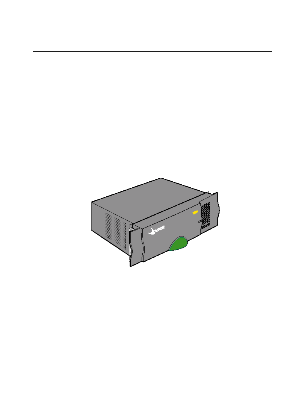
Figure 1-1 shows available Vanguard 7300 Version 1 Series routers.
Vanguard Model 7310
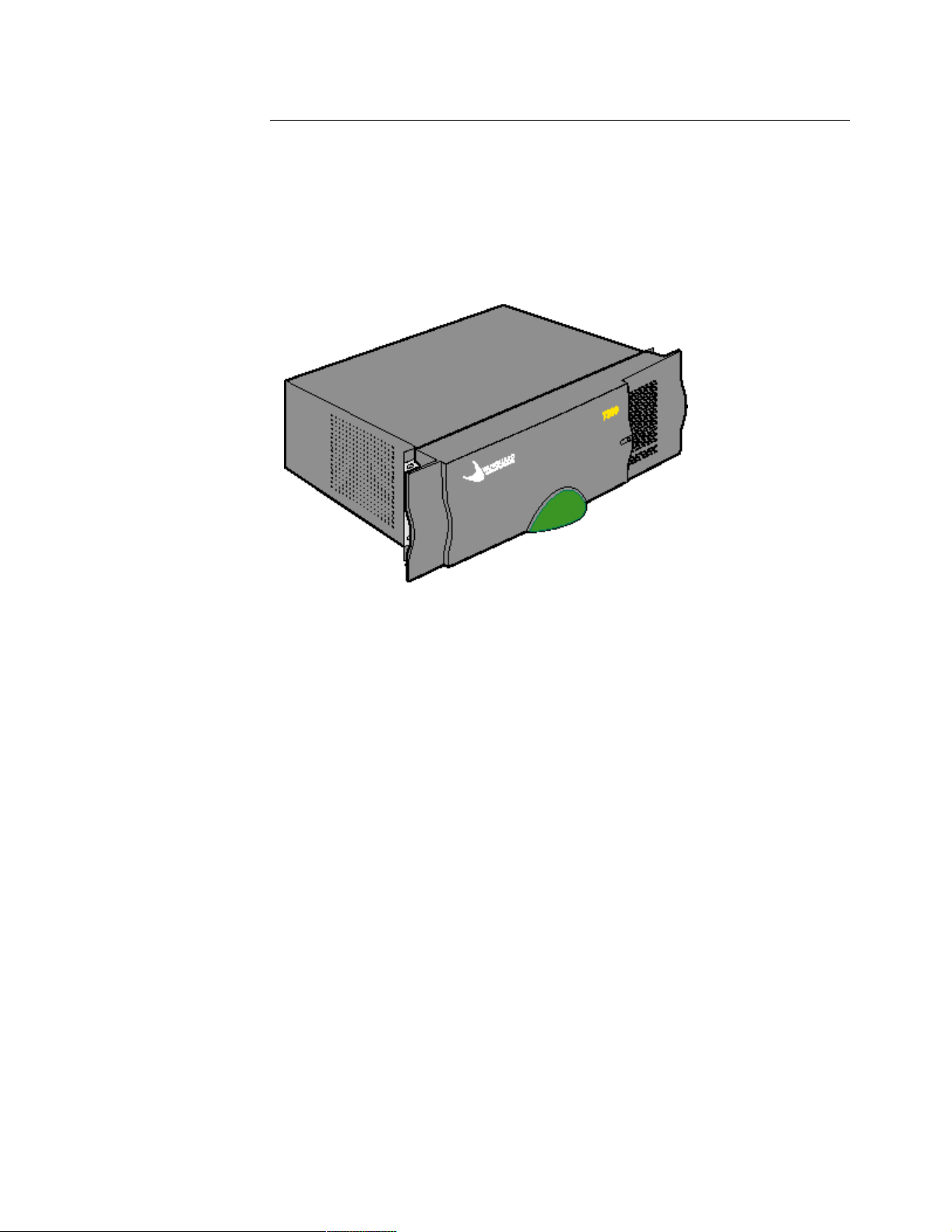
Vanguard Model 7330
Figure 1-1. Vanguard 7300 Series Routers - Version 1
1-2 About Vanguard 7300
Page 15
Vanguard 7300 Functions and Features
Scalable Hardware
Platforms
Version 2
The Vanguard 7300 Series Version 2 has a new redesigned chassis available in the
following models:
• The 5-slot Vanguard 7310 with built-in dual redundant power supplies
• The 8-slot Vanguard 7330 with built-in dual redundant power supplies
With the Version 2 redesign the Vanguard 7310 5-slot and the Vanguard 7330 8-slot
use the same enclosure, power supplies and fan unit.
Figure 1-2 shows available Vanguard 7300 Version 2 Series routers.
Vanguard Version 2
7310 and 7330
Figure 1-2. Vanguard 7300 Series Routers - Version 2
About Vanguard 7300 1-3
Page 16

Vanguard 7300 Functions and Features
Feature Cards and
Mezzanine Cards
Vanguard 7300 Series products are highly scalable with Vanguard Managed
Solutions-supplied option cards and half-size Mezzanine Cards. Currently Vanguard
7300 Series products support these full-size cards:
• Processor Card (the Central Processor Unit (CPU))
- MPC750 - with a 10/100BaseT Ethernet port
- IBM750FX - with two 10/100/1000BaseT Ethernet ports
• Carrier Expansion Card
• T1/E1/PRI Card with T1/E1/PRI Rear Transition Module
• T3/E3 ATM Card that includes:
- Standard Carrier Expansion Card
- T3/E3 Rear Transition Module
• Serial Card with Serial Rear Transition Module
• Token Ring Card
Each of these cards occupies a full slot in a Vanguard 7300 chassis.
The Vanguard 7300 Series also supports the following half-size piggyback cards,
Peripheral Component Interconnect (PCI) Mezzanine Cards, known as PMCs:
• 10/100BaseT Ethernet PCI Mezzanine Card (PMC)
• Voice PCI Mezzanine Card (a custom T1/E1/PRI card PMC)
• T3 ATM PCI Mezzanine Card (a custom T3 ATM card PMC)
• Advanced Encryption Card (AEC)
A Vanguard 7300 PMC does not require a chassis slot, but mounts on top of one of
the full-size Vanguard 7300 cards. The full-size card serves as the PMC’s host.
For example, a single 10/100 BaseT Ethernet PMC can be hosted by the Vanguard
7300 CPU Card, or two 10/100 BaseT Ethernet PMCs can be hosted by the Carrier
Expansion Card. The T1/E/1PRI Card’s Voice PMC can only be hosted by a
Vanguard 7300’s T1/E1/PRI Card.
Detailed
Information
For a detailed description of Vanguard 7300 Series chassis and Vanguard Managed
Solutions-supplied full-card/PMC combinations, refer to:
• Chapter 2, Vanguard 7300 Enclosures and Components
• Chapter 3, Vanguard 7300 Installation
• Chapter 4, Operating Your Vanguard 7300
• Chapter 5, Modifying Your Vanguard 7300
• Chapter 6, Replacing Power Supplies and Cooling Fans
The following appendices and supplementary documentation are provided at the end
of this manual:
• Appendix A, Specifications
• Appendix B, Vanguard 7300 Cable Connectors and Pinouts
• Appendix C, Vanguard 7300 Software License and Regulatory Information
• Vanguard 7300 Glossary of Terms
An index of the entire Vanguard 7300 Installation Manual is provided in the last
pages of this manual.
1-4 About Vanguard 7300
Page 17

Vanguard 7300 Functions and Features
Software Support The Vanguard 7300 operates under the Vanguard Applications Ware software and
supports the following licensing packages:
Base Licenses:
• IP+ Applications Ware (includes IP, IPX, and Voice)
• SNA+ Applications Ware (includes IP, IPX, SNA, and Voice)
• Multiservice Applications Ware
Note
For more information on the license upgrades available for the Vanguard 7300
Series, refer to the Software Release Notice.
Pre-loaded software stored in the CPU card’s on-board flash memory allows smooth
transition from power-up to configuring your Vanguard 7300 network node with the
Vanguard Managed Solutions Vanguard Applications Ware. Power-up procedures
and configuration port numbering are described in Chapter 4, Operating Your
Vanguard 7300.
Note
Software is stored in the primary FLASH, not alternate FLASH.
For an up-to-date detailed list of software functions supported by Vanguard 7300
Series routers and Vanguard Applications Ware, refer to the latest version of the
Software Release Notice and product documentation updates posted on the Vanguard
Managed Solutions Product Documentation web site at:
http://www.vanguardms.com/support/documentation
Refer to the Vanguide CD-ROM’s library of Vanguide manuals for node
configuration documentation.
About Vanguard 7300 1-5
Page 18

Vanguard 7300 Functions and Features
Advanced Encryption Card (AEC)
Data Encryption Data encryption is a very CPU intensive process and is best implemented in
hardware. Vanguard Managed Solution’s provides a secure hardware-based
encryption and compression. Release 6.4 and greater supports the Advanced
Encryption Card (AEC).
Note
Data compression is not supported on the Vanguard 7300
Advanced Encryption Card.
The Advanced Encryption Card information is located in Chapter Two of this
manual. Installation instructions are available in Chapter Five.
For additional information on Encryption configuration refer to the Vanguard Data
Encryption Manual (Part Number T0103-09) and the Vanguard Virtual Private
Network (VPN) Manual (Part Number T0103-10).
1-6 About Vanguard 7300
Page 19

Compression
When compressed traffic is sent over a Frame Relay link on the Vanguard 7300
Series, some compressed transmitted frames might corrupt. Vanguard Managed
Solutions recommends that you change the maximum frame size in the Node Record
Configuration from the default of 1620 to 2200. This is the recommended default
whenever compression is activated on a frame relay bypass station on a Vanguard
7300.
Vanguard 7300 Functions and Features
About Vanguard 7300 1-7
Page 20
Vanguard 7300 Applications
Vanguard 7300 Applications
Introduction This section describes a few typical applications for Vanguard 7300 Series products.
Frame Relay to
ATM Environment
Figure 1-3 shows a Vanguard Series router used to support T3/E3 Access for IP and
voice traffic over a frame relay to ATM network. To support this network
environment the 7300 device requires:
• T3/E3 ATM Card to support T3/E3 ATM access to the ATM Network
• T1/E1/PRI cards equipped with Voice Server PMCs to support packetized
voice and connection to the PBX/PSTN
• 10/100BaseT Ethernet PMCs
Figure 1-3. Frame Relay to ATM Environment
1-8 About Vanguard 7300
Page 21
Vanguard 7300 Applications
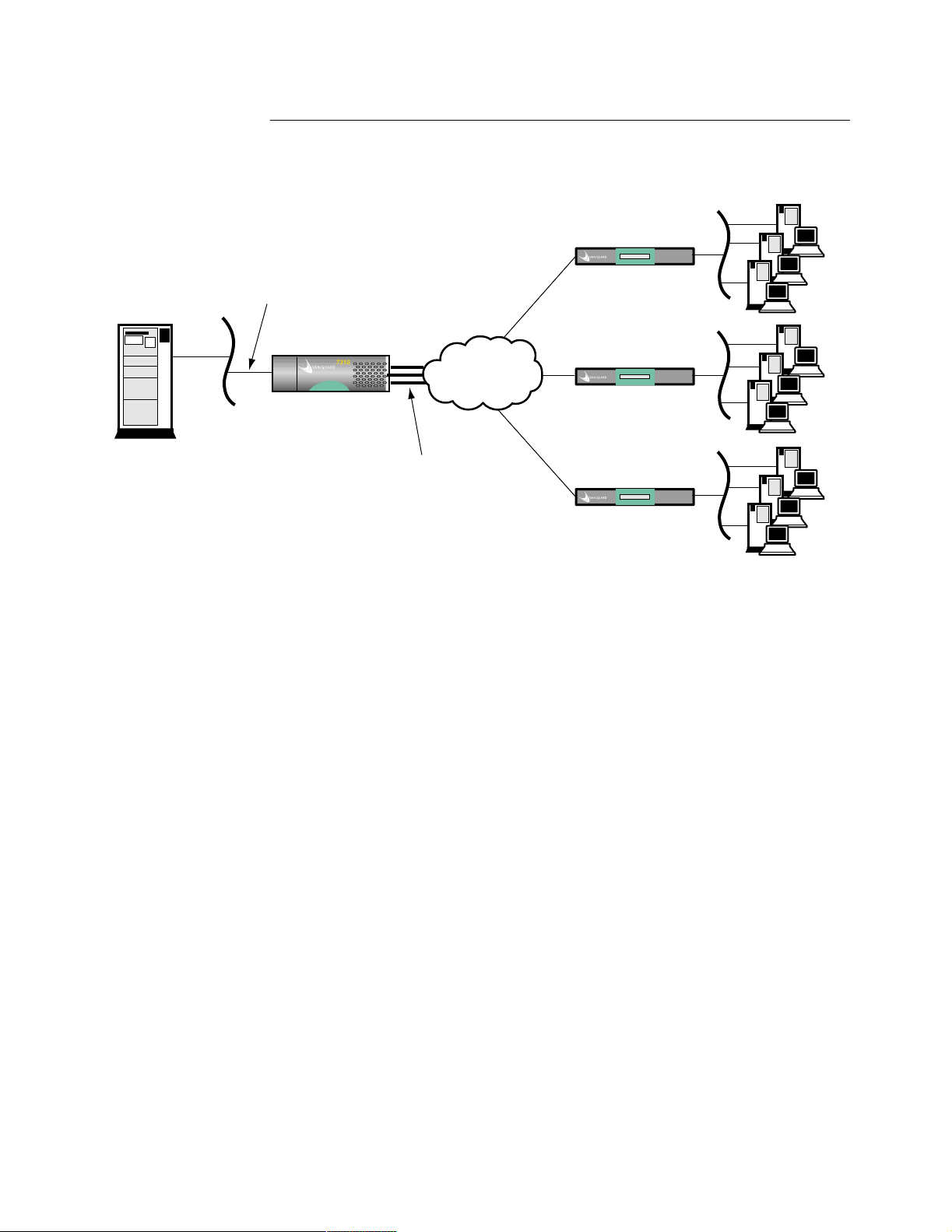
IP Routing Traffic Figure 1-4 shows a Vanguard 7300 Series router used to provide support for
high-speed LAN IP routing in a Frame Relay, IP network environment. The
Vanguard 7310 is equipped with 10/100BaseT Ethernet PMCs and T1/E1/PRI cards.
Host Server
10/100BaseT
Ethernet
Vanguard 7330
T1
Frame Relay
or IP Network
7310
T1
Multiple T1/E1 Lines
Vanguard 6400
T1
Vanguard 6400
Vanguard 6400
Figure 1-4. Vanguard 7310 Used for High-Speed LAN IP Routing
About Vanguard 7300 1-9
Page 22
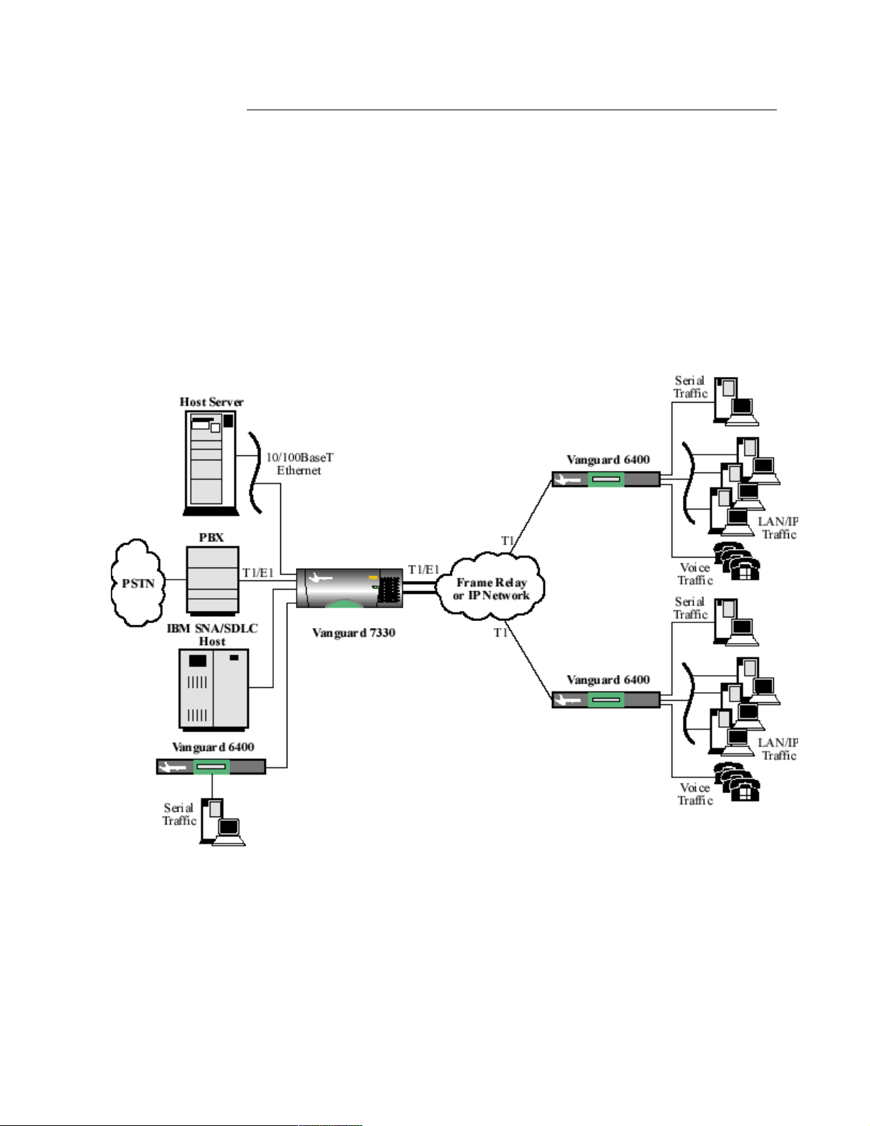
Vanguard 7300 Applications
Multiservice IP,
SNA, Serial and
Voice Traffic
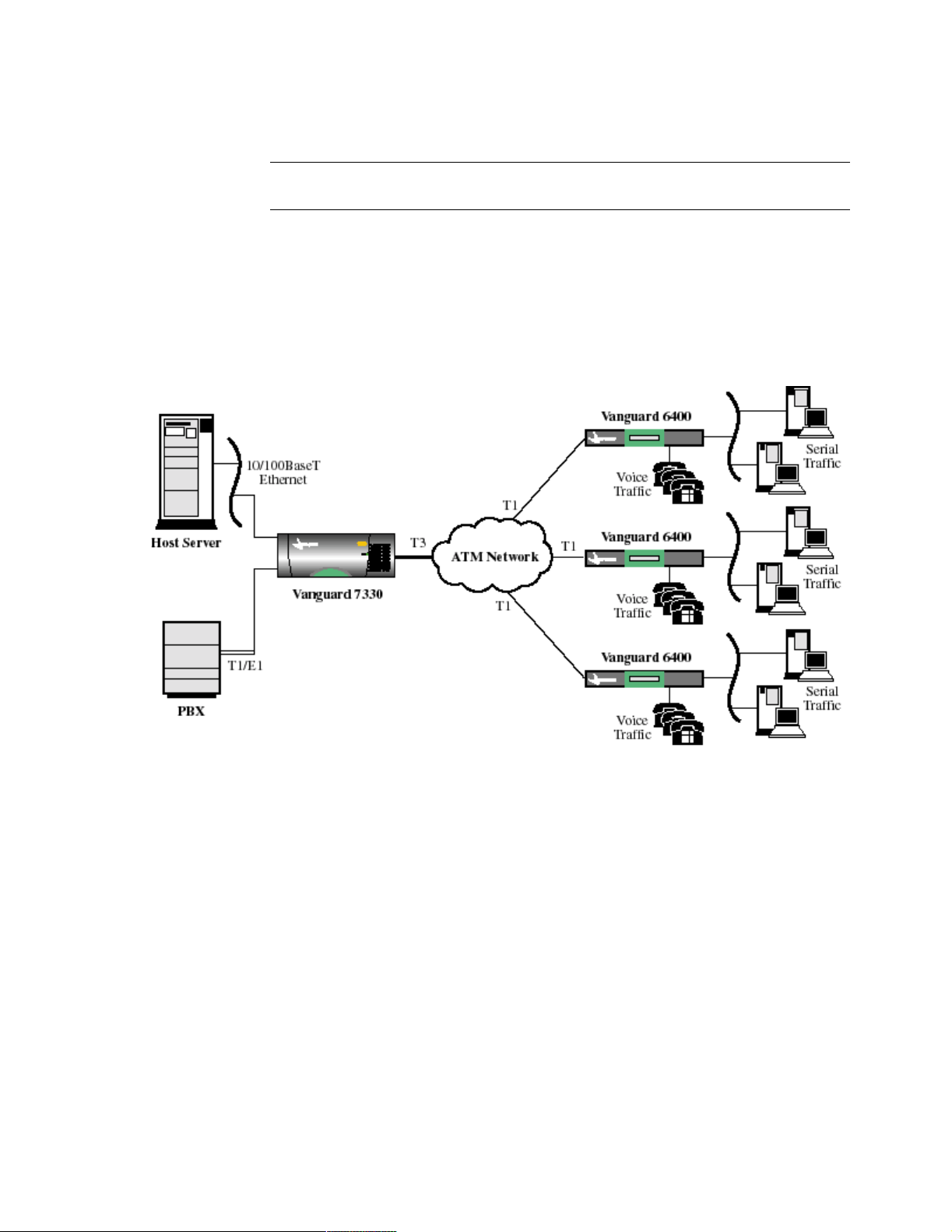
Figure 1-5 shows a Vanguard Series router used to support mixed IP, SNA, serial,
and voice traffic. To support this network environment the 7310 requires:
• T1/E1/PRI cards to support multiple T1/E1 interfaces to the Frame Relay or
IP Network
• T1/E1/PRI cards equipped with Voice Server PMCs to support packetized
voice and connection to the PBX/PSTN
• Serial cards to support connection of SNA/SDLC hosts and to interconnect to
Vanguard 6400s, which can be used to connect older, legacy devices
• 10/100BaseT Ethernet PMCs
Note that the Vanguard 7300 supports SNA/SDLC, and TBOP serial protocol traffic
along with Frame Relay, X.25, and so forth.
Figure 1-5. Multiservice IP, SNA, Serial, and Voice Traffic
1-10 About Vanguard 7300
Page 23
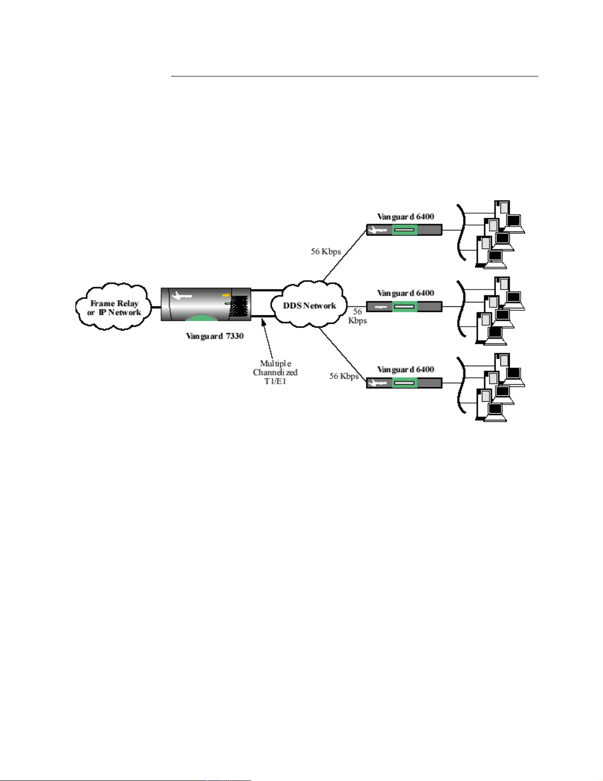
Vanguard 7300 Applications
Regional
Concentrator with
Multiple LowSpeed WAN Ports
Figure 1-6 shows a Vanguard 7300 Series router used in a regional concentration
application. As a regional concentrator, the 7330 is located in large branch offices to
terminate branch traffic and provide regional switching and routing functions. In
addition, the 7330 can concentrate regional traffic onto a single high-speed link for
transmission to the head office.
The Vanguard 7330 supports a large number of low-speed WAN ports (from 56, 64
or 384 Kbps) or channelized T1/E1 ports for Digital Data Service (DDS) access.
Figure 1-6. Regional Concentrator with Multiple Low-speed WAN Ports
About Vanguard 7300 1-11
Page 24
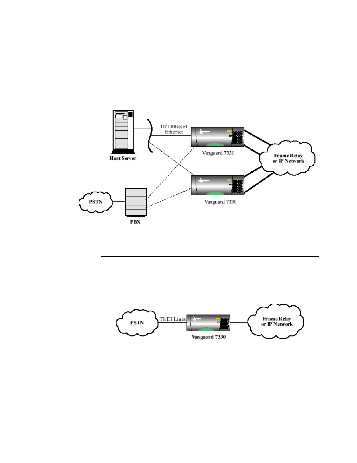
Vanguard 7300 Applications
Large Networking
Solution Using
Multiple Vanguard
7300’s
Figure 1-7 illustrates multiple Vanguard 7300 devices in very large networks. In
this example, traffic is distributed across a numbers of Vanguard 7300’s for
load-balancing and redundancy. Network connections are made via multiple T1/E1
interfaces.
The example shows redundant Vanguard 7330s, each connected to multiple
applications. Note that each Vanguard 7330 has a voice connection to the PBX and
an Ethernet connection to the host server.
Small-to-Medium
Alternate Carriers
Voice Gateways
Figure 1-7. Large Network Solution With Redundant Vanguard 7330s
Figure 1-8 shows an application in which a Vanguard 7300 Series router is used in
large alternate carriers and small central office (CO) environments. The Vanguard
7330 router, equipped with T1/E1/PRI cards with Voice Server PMCs, supports
Public Switched Telephone Network (PSTN) voice applications.
Figure 1-8. Small-to-Medium Alternate Carriers Voice Gateways
1-12 About Vanguard 7300
Page 25

Vanguard 7300 Platform Version 1
Vanguard 7300 Platform Version 1
Introduction This section describes the Vanguard 7300 Platform.
The Vanguard 7300
Platform
The Vanguard 7300 Version 1 Series chassis with its standardized CompactPCI bus
architecture permits high-speed, high-availability, compute-intensive
telecommunication applications. With its extremely high bandwidth and hot-swap
capability, the CompactPCI bus is ideal for high-speed data communication
telecommunication industry applications.
About Vanguard 7300 1-13
Page 26
Vanguard 7300 Platform Version 1
The Vanguard 7300 Chassis Version 1
Introduction Vanguard 7300 Series chassis fit standard equipment racks, and the cards have
PICMG standardized telecom-grade connectors. Hot-swappable boards and power
supplies can be removed and replaced without taking the router out its rack and
without disconnecting unrelated cables.
7310 and 7330
Routers
The combination of the CompactPCI bus, special-purpose, metal-front, screwfastened PCI cards, half-size PMCs, and rear-cabled I/O transition modules provides
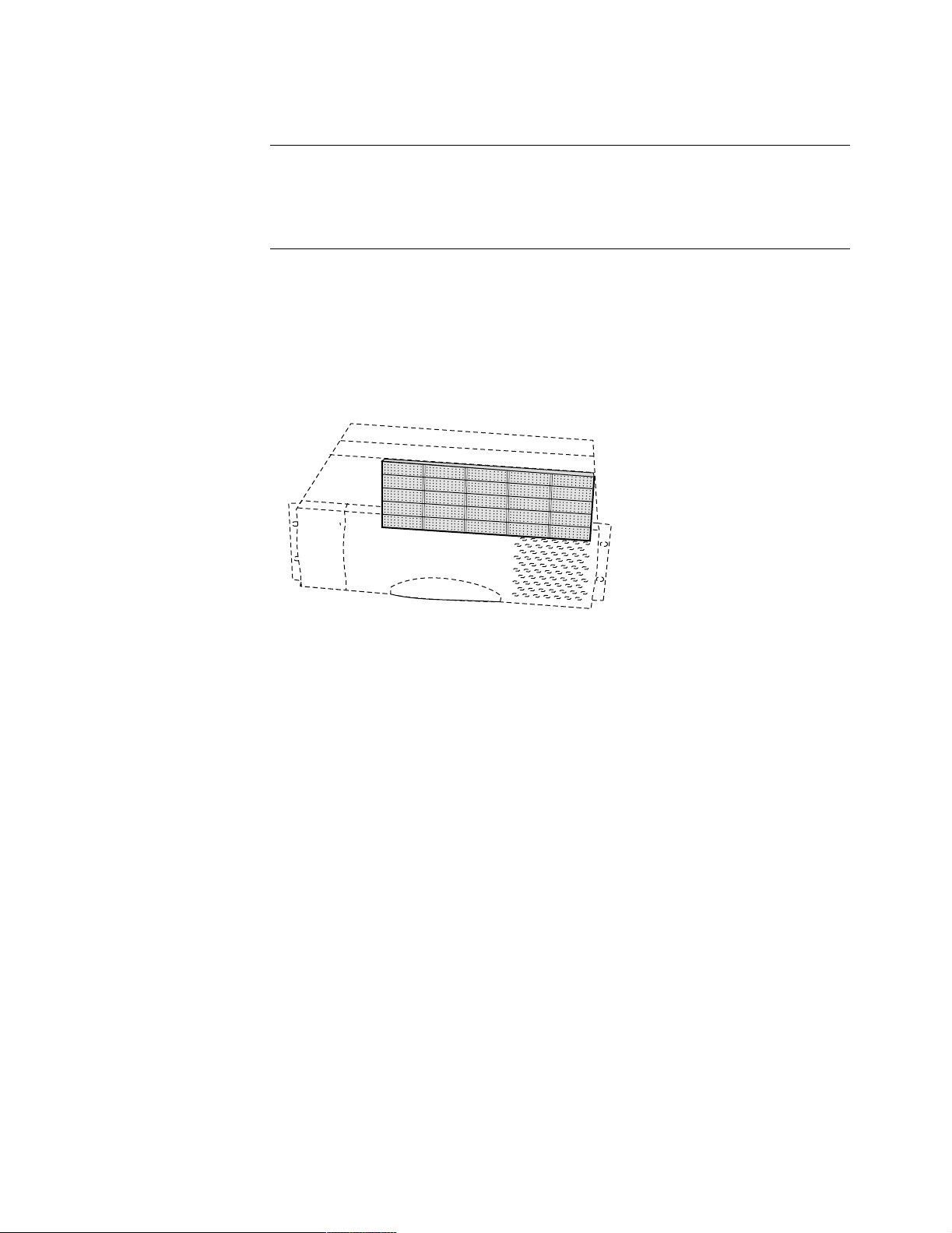
reliable, high-performance solutions for the most demanding routing environment.
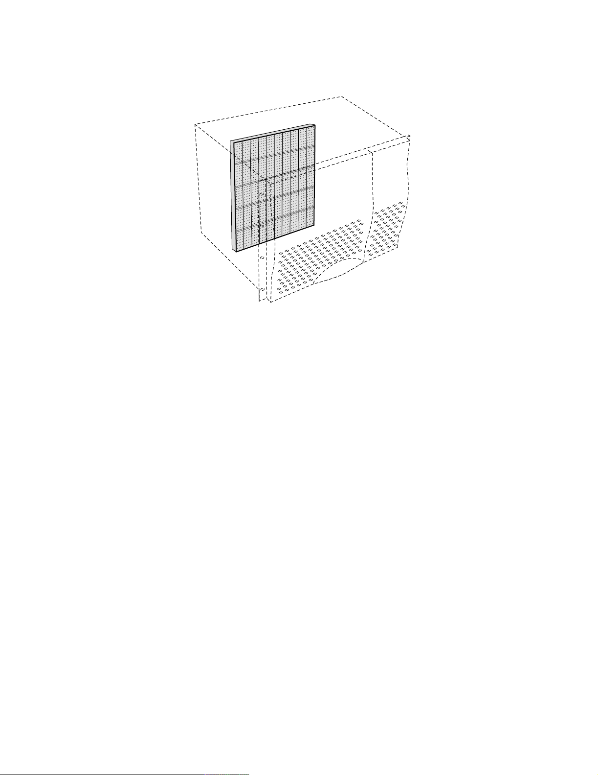
For a cutaway view of the center midplane CompactPCI bus design implemented in
Vanguard 7300 Version 1 Series routers, refer to Figure 1-9 and Figure 1-10.
Chassis Rear
Ve rs i o n 1
Chassis Front
Figure 1-9. 7310 Midplane and Card Connectors, Cutaway Diagram
1-14 About Vanguard 7300
Page 27
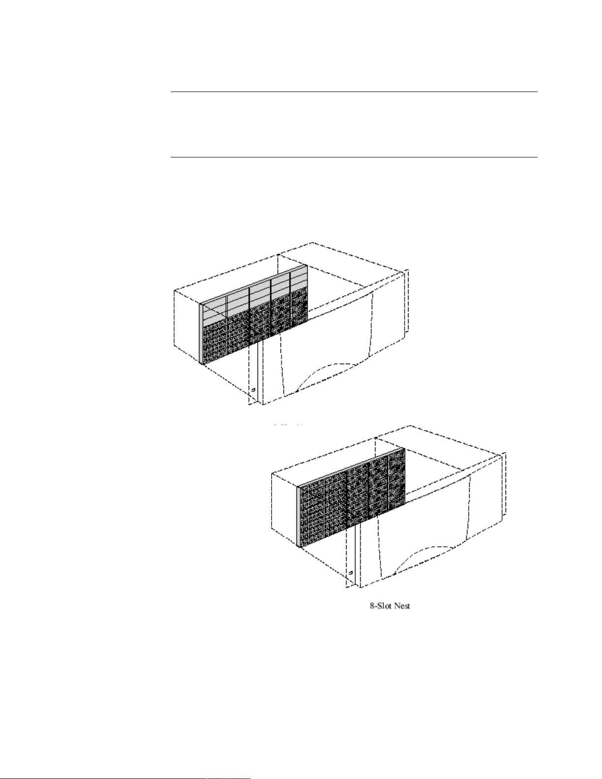
Chassis Rear
Vanguard 7300 Platform Version 1
Ve rs i o n 1
Chassis Front
Figure 1-10. 7330 Midplane and Card Connectors, Cutaway Diagram
About Vanguard 7300 1-15
Page 28

Vanguard 7300 Platform Version 2
Introduction This section describes the Vanguard 7300 Platform.
The Vanguard 7300
Platform
The Vanguard 7300 Version 2 Series chassis with its standardized CompactPCI bus
architecture permits high-speed, high-availability, compute-intensive
telecommunication applications. With its extremely high bandwidth and hot-swap
capability, the CompactPCI bus is ideal for high-speed data communication
telecommunication industry applications.
Page 29
Vanguard 7300 Platform Version 2
The Vanguard 7300 Chassis - Version 2
Introduction Vanguard 7300 Series chassis fit standard equipment racks, and the cards have
PICMG standardized telecom-grade connectors. Hot-swappable boards and power
supplies can be removed and replaced without taking the router out its rack and
without disconnecting unrelated cables.
7310 and 7330
Routers
The combination of the CompactPCI bus, special-purpose, metal-front, screwfastened PCI cards, half-size PMCs, and rear-cabled I/O transition modules provides
reliable, high-performance solutions for the most demanding routing environment.
For a cutaway view of the center midplane CompactPCI bus design implemented in
Vanguard 7300 Revision 2 Series router, refer to Figure 1-11.
Chassis rear
Vanguard 7310 and 7330
Ve rs i o n 2
Chassis front
Figure 1-11. 7310 and 7330 Midplane and Card Connectors, Cutaway
Diagram for Version 2
About Vanguard 7300 1-17
Page 30
Vanguard 7300 Platform Version 2
Vanguard 7300 Cards
Description The Vanguard 7300’s midplane slots hold special-purpose printed circuit cards
and rear transition modules accessible from both the front and the rear of the
rack-mounted chassis. Card-swapping time is minimized, port cabling is organized,
and low-level software customizing is eliminated.
Depending on its purpose, a CompactPCI card can be:
• A single card with or without connectors that inserts into a front chassis slot
• A single card with one or more half-sized PMCs mounted on it that inserts
into a front chassis slot
• A two-part card that inserts into a front chassis slot and requires a rear
transition module inserted into its matching rear chassis slot
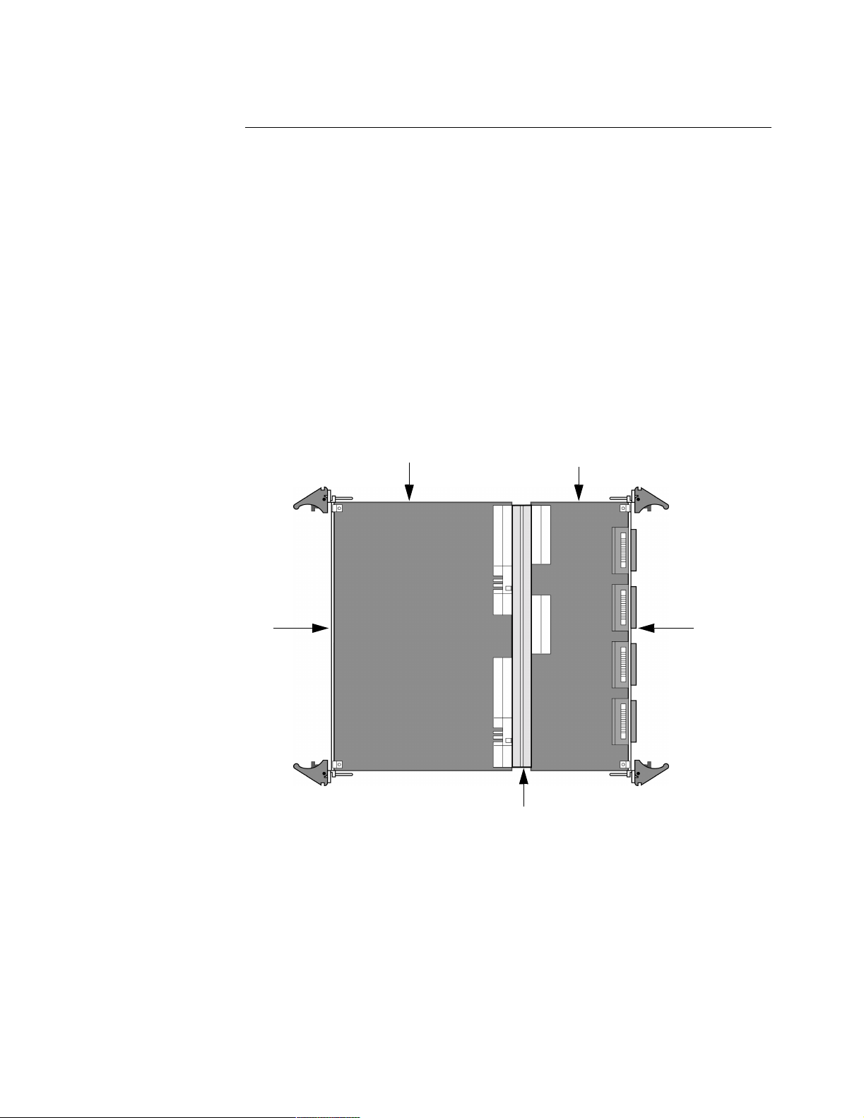
Figure 1-12 shows a two-part Serial card plugged into the front and rear of the
Vanguard 7300 midplane. The rear transition module has eight ports for cabling from
the rear of the chassis. Fasteners on every card or module lock it securely in its
chassis slot and indicate that the card or module is seated properly.
Chassis Front
Figure 1-12. Two-Part Serial Card for the Vanguard 7300 Series
PCI Front Printed
Circuit Card
PCI Rear Transition
Module
Chassis Rear
Compact PCI Midplane
1-18 About Vanguard 7300
Page 31

Vanguard 7300 Platform Version 2
CompactPCI Connectors
Description The CompactPCI midplane is located toward the middle of the chassis, and each card
slot is equipped with male J1 connectors (pins). The plug-in cards use socket
(female) connectors. The same type of connectors are used on the rear side of the
midplane to accept rear I/O transition modules. Midplane connectors have external
metal shields for proper shielding and grounding in noisy environments. Controlled
impedance minimizes unwanted signal reflections.
Figure 1-13 shows the standard five CompactPCI card connectors that make up the
CompactPCI bus interface and the user input/output sub-bus. The following table
summarizes the function of the standard card connectors:
Bus Type Connector Purpose
CompactPCI
Bus
User I/O
Bus
J1 32-bit CompactPCI connector
J2 64-bit CompactPCI connector
J3 I/O Signal Distribution
J4 H.110 bus access
J5 External I/O (Telephony) access
User I/O
or
Sub-Bus
Te le ph o ny
I/O
Compact
PCI Bus
6U
Compact PCI Card
Shielded Compact
PCI Rear Transition
Module
Figure 1-13. CompactPCI Bus Connectors (Side View)
About Vanguard 7300 1-19
Page 32

Vanguard 7300 Platform Version 2
CompactPCI cards and rear transition modules plug into the midplane’s front and
rear pin connectors. Each card or module uses IEC-approved 110-pin connectors for
power, ground, and all 32-bit and 64-bit PCI signals, rather than card-edge
connectors. See Figure 1-14 for views of chassis slot female connector sockets.
Individual 110-
Pin Connector
Front Card Slot
Connectors (5)
Figure 1-14. CompactPCI Connectors (Front View)
Rear Transition
Module Connector
(32-bit, User I/O)
1-20 About Vanguard 7300
Page 33

Chapter 2
Vanguard 7300 Enclosures and Components
Overview
Introduction This chapter describes Vanguard 7300 Series chassis enclosures and provides
detailed descriptions of available hardware options and feature cards. These topics
are discussed:
•Enclosures
• Vanguard 7300 Cards
Vanguard 7300 Enclosures and Components 2-1
Page 34

Enclosures
Enclosures
Introduction Vanguard 7300 Version 1 and Version 2 Series Routers have distinct enclosures:
Vanguard 7300 Revision 1 Series routers:
• The Vanguard 7310 has a horizontal five-slot chassis
• The Vanguard 7330 has a vertical eight-slot vertical chassis
Vanguard 7300 Version 2 Series routers:
• The Vanguard 7310 has a horizontal five-slot chassis
• The Vanguard 7330 has a horizontal eight-slot chassis
7300 Version 1
Enclosure Features
Number of Slots 5 (horizontal) 8 (vertical)
Height 3U 8U
Rack-mountable Yes Yes
Redundant AC and DC Power none Yes, dual power supplies
7300 Version 2
Enclosure Features
Number of Slots 5 (horizontal) 8 (horizontal)
Height 4U 4U
Rack-mountable Yes Yes
Redundant AC and DC Power Yes, dual power supplies Yes, dual power supplies
Figure 2-1 show the Vanguard 7300 Version 1 Series enclosures. This table
summarizes common and distinct features of each enclosure:
Feature Vanguard 7310
Version 1
Figure 2-2 show the Vanguard 7300 Version 2 Series enclosure. This table
summarizes common and distinct features of the enclosure:
Feature Vanguard 7310
Version 2
Vanguard 7330
Version 1
Vanguard 7330
Version 2
2-2 Vanguard 7300 Enclosures and Components
Page 35

height = 5.25 in
Enclosures
width = 17.5 in
depth = 16.5 in
Vanguard 7310 Version 1
height = 14.0 in
Figure 2-1. Vanguard 7300 Version 1 Series Enclosure Views
Vanguard 7310 and 7330 Version 2
width = 17.3 in
depth = 16.0 in
Vanguard 7330 Version 1
depth = 13.4 in.
height = 7 in.
width = 17.3 in.
Figure 2-2. Vanguard 7300 Version 2 Series Enclosure Views
Vanguard 7300 Enclosures and Components 2-3
Page 36

Enclosures
Vanguard 7310 Version 1 Enclosure
Vanguard 7310
Enclosure Features
Version 1
Front Panel of the
Vanguard 7310
Version 1
Enclosure
The Vanguard Model 7310 Version 1 enclosure offers these features:
• Five horizontal card slots
• 3U (5.25 inch) vertical rack height
• Rack-mountable in a standard 19-inch rack
• Processor card (CPU) (purchased separately)
• AC or DC Power Supply Module and Inlet Fan Module (front access)
• Power Input Module (rear access)
• Exhaust Fan Module
• Front access for service and installation of cards, fan, power supply and
interface connectors for Vanguard Managed Solutions-supplied CPU and PCI
Mezzanine Cards (PMC)
• Rear access for power connection, power switch, and interface connectors for:
- T1/E1/PRI cards
- T3/E3 ATM Cards
- Serial cards
The Vanguard 7310 front panel (Figure 2-3) provides access to:
• Front panel connectors of the CPU Card
• Front panel connectors of the PMCs (if installed)
Exhaust Fan
Module
Carrier Card with
Two E th er net
PMC
MPC750 CPU Card
Power Supply &
Inlet Fan Module
Serial I/O
Universal
ACT 100bT LINK
PORT 1
PCI MEZZANINE CARD
P
C
M
PORT 2
ACT 100bT LINK
PORT 1
PORT 2
2
P
C
M
CPU
PCI
ABT
RST
BFL
CPCI
ACT 100bT LINK
PORT 1
1
USB 1COM 110/100 BASE T USB 0
PORT 2
1173
RESET
8
W
EXTPWR
4
0
HOT SWAP
A
N
DEB
U
G
EXT PWR
Figure 2-3. Front View of Vanguard 7310 Version 1 Enclosure
2-4 Vanguard 7300 Enclosures and Components
Page 37

Enclosures
Rear of the
Vanguard 7310
Version 1
Enclosure
Regulatory
Label (Side)
Dual Earth
Ground
The rear of the Vanguard 7310 Version 1 (Figure 2-4) provides access to:
• Power connections and power switch of the power input module
• Serial number of the Vanguard 7310 enclosure
• Rear panel connectors for installed T1/E1/PRI, T3/E3 ATM, and Serial Rear
Transition Modules
Note
Vanguard Series router cards have front and/or rear connectors. Refer to the
“Vanguard 7300 Cards” section on page 2-12 for specific card connector details.
AC Power
Input Module
Power
Switch
T3/E3 Rear
Tran sition
Module
Exhaust Fan
Module
ESC Bond
Point
Vanguard 7310
Version 1 Chassis
Dimensions
AC Power
Receptacle
Serial Rear
Transition
Module
T1/E1/PRI
Rear Transition
Module
Serial No.
Location
Figure 2-4. Rear View of Vanguard 7310 Version 1 Enclosure
• Height: 5.25 inches (133.35 mm)
• Width: 17.50 inches (444.50 mm)
• Depth: 16.5 inches (419.1mm)
• Weight: 30 lbs. (13.6kg) unloaded; approx. 35 lbs. (15.9kg) configuration
dependent
Vanguard 7300 Enclosures and Components 2-5
Page 38

Enclosures
Vanguard 7330 Version 1 Enclosure
Vanguard 7330
Version 1
Enclosure Features
Vanguard 7330
Version 1
Enclosure, Front
Panel
The Vanguard Model 7330 Version 1 router enclosure has the following features:
• Eight vertical card slots
• 8U vertical rack height
• Rack-mountable in standard 19-inch rack
• CPU card (purchased separately)
• Two hot-swappable AC or DC power supply modules
• Hot-swap fan tray
• Front access for installation, service, fan tray access and cabling
• Rear access to the power supplies, card interface connectors, and cabling
The Vanguard Model 7330 Version 1 front panel (Figure 2-5) provides access to:
•Power switch
• Hot-swap fan tray
• Front-panel connectors for the CPU Card
• Front-panel connectors for any installed PMCs
Carrier Card
with PMCs
CPU Card
Serial No.
Location
Serial
Card
T1/E1/PRI
Card
Carrier Card
w it h T 3/ E3 ATM
PMC
Hot-swap
Fan Tray
Power
Switch
Figure 2-5. Vanguard 7330 Version 1 Enclosure, Front View
2-6 Vanguard 7300 Enclosures and Components
Page 39

Enclosures
Rear View The Vanguard 7330 Version 1 rear panel (Figure 2-6) provides access to AC power
cord receptacles and T1/E1/PRI, T3/E3 ATM and Serial Rear Transition Module
connectors.
ESD Bond
Point
T3/E3 Rear
Transition
Module
T1/E1/PRI Rear
Tran sition
Module
Serial Rear
Transition
Module
Serial No.
Location
AC Power Cord
Receptacles
Figure 2-6. Vanguard 7330 Version 1 Enclosure Rear View
Vanguard 7300 Enclosures and Components 2-7
Page 40

Enclosures
Vanguard 7330
Version 1 Fan Tray
Vanguard 7330
Version 1
Removable Filler
Panels
Vanguard 7330
Version 1 Chassis
Dimensions
You can install and remove the fan tray from the front of the Vanguard 7330
enclosure. The fan tray is hot-swappable; it can be removed without turning off the
system power and without disrupting system service.
Caution
To prevent the Vanguard Model 7330 from overheating, install the replacement fan
tray immediately.
Front and rear filler panels can be removed to install card and transition modules.
The Vanguard 7330 chassis dimensions are:
Height: 14 inches (8U, 355.6 mm)
Width: 17.3 inches (439.4 mm)
Depth: 16 inches (365.8 mm)
Weight: 40 lbs. (18 kg) with two AC or DC power supplies and without cards
2-8 Vanguard 7300 Enclosures and Components
Page 41

Vanguard 7310 and 7330 Version 2 Enclosure
Enclosures
Vanguard 7310 and
7330 Version 2
Enclosure Features
Vanguard 7310 and
7330 Version 2
Enclosure, Front
Panel
The Vanguard Model 7310 and 7330 Version 2 router enclosure has the following
features:
• Eight horizontal card slots - 7330
• Five horizontal card slots - 7310
• 4U vertical rack height
• Rack-mountable in standard 19-inch rack
• CPU card (purchased separately)
• Two hot-swappable AC or DC power supply modules
• Hot-swap fan assemblies
• Front access for installation, service, intake fan assemblies access,
power supplies and cabling
• Rear access to the exhaust fan assemblies, card interface connectors, and
cabling
The Vanguard Model 7310 and 7330 Version 2 front panel (Figure 2-7) provides
access to:
•Power switch
• Intake fan assemblies
• Power supplies
• Front-panel connectors for the CPU Card
• Front-panel connectors for any installed PMCs
Main Power Switch
Figure 2-7. Vanguard 7310 and 7330 Version 2 Enclosure, Front View
Vanguard 7300 Enclosures and Components 2-9
Page 42

Enclosures
Rear View The Vanguard 7310 and 7330 Version 2 rear panel (Figure 2-8) provides access to
AC power cord receptacles and T1/E1/PRI, T3/E3 ATM and Serial Rear Transition
Module connectors.
Figure 2-8. Vanguard 7310 and 7330 Version 2 Enclosure Rear View
2-10 Vanguard 7300 Enclosures and Components
Page 43

Enclosures
Vanguard 7310 and
7330 Version 2 Fan
assemblies
Vanguard 7310 and
7330 Version 2
Removable Filler
Panels
Vanguard 7310 and
7330 Version 2
Chassis
Dimensions
You can install and remove the intake fan assemblies from the front of the Vanguard
7310 and 7330 enclosure. The fan assemblies are hot-swappable; they can be
removed without turning off the system power and without disrupting system
service. You can install and remove the exhaust fan assembly from the rear.
Caution
To prevent the Vanguard Model 7310 and 7330 from overheating, install the
replacement fan assemblies immediately.
Front and rear filler panels can be removed to install card and transition modules.
The Vanguard 7310 and 7330 Version 2 chassis dimensions are:
Height: 7 inches (4U)
Width: 17.3 inches (439.4 mm)
Depth: 13.4 inches
Weight: 22 lbs.
Vanguard 7300 Enclosures and Components 2-11
Page 44

Vanguard 7300 Cards
Vanguard 7300 Cards
Introduction These subsections describe the Vanguard Managed Solutions-supplied cards that are
fully compatible and can be installed in the Vanguard 7300 Version 1 and Version 2
Series routers:
• “Central Processor Unit (CPU) Cards” on page 2-13
- MPC750 CPU
- IBM750FX CPU
• “Carrier Expansion Card” on page 2-21
• “Dual-port 10/100BaseT Ethernet Mezzanine Card (PMC)” on page 2-23
• “T1/E1/PRI Card and Rear Transition Module” section on page 2-25
• “T3/E3 ATM Mezzanine Card (PMC)” on page 2-32
• “Voice Server/DSP Mezzanine Card (PMC)” on page 2-27
• “Serial Card and Rear Transition Module” section on page 2-34
• “Token Ring Card” section on page 2-39
• “Advanced Encryption Card (AEC)” section on page 2-41
2-12 Vanguard 7300 Enclosures and Components
Page 45

Vanguard 7300 Cards
Central Processor Unit (CPU) Cards
Introduction There are two types of Central Processor Unit (CPU) cards that are supported in the
Vanguard 7300 Series Platform:
• MPC750 CPU card
• IBM750FX CPU card
CPU Card Product
Code
MPC750 53120 75836G02 6.4 or earlier 6.4 or earlier
IBM750FX 1112-10011 76361G01 6.4 or greater 6.4 or greater
Part Number Software
Release
Bootprom
Central Processor Unit (CPU) Card - MPC750
Functions The MPC750 Series 7300 central processor unit (CPU) card provides system
processor functions for Vanguard 7300 Series products. The CPU card provides
system clocks and bus arbitration for all peripheral slots in Vanguard 7300 Series
products.
Note
The MPC750 card is supported on all 7300 software and bootprom
software releases.
This table lists the MPC750 CPU card features:
Function Description
Memory 128MB RAM
Compact Flash Memory A 32MB Compact Flash Memory card installed
Processor 366 MHz MPC750 PowerPC Processor
Real-time Clock Real-time Clock with non-field replaceable lithium
battery backup
Slots Has one slot for an industry-standard, IEEE P1386.1
PMC
On-board Interfaces • Auto-sensing 10/100BaseT Ethernet port
• Async CTP port
– DB9 crossover cable
USB 0 and 1 Not used
Vanguard 7300 Enclosures and Components 2-13
Page 46

Vanguard 7300 Cards
CPU Board Layout Figure 2-9 shows the layout of the Vanguard 7300 Series CPU card. Note that there
is room on the CPU card beside the Memory PMC for installing the two-port
Ethernet PMC (described in Chapter 5).
Pre-installed
Memory PMC
Flash Memory
CPU Card Serial
No. Location
Figure 2-9. Vanguard 7300 Series CPU Card, MPC750
CPU Card
Installation
Information
The MPC750 CPU card must reside in the system slot of Vanguard 7300 Series
products. Slot 1 is the system slot on Vanguard 7300 Series routers. Only one CPU
card can be installed in a Vanguard 7300. Refer to “Removing and Replacing the
CPU Card and CPU Mezzanine Card (PMC)” section on page 5-11 for CPU card
installation instructions.
PCI Mezzanine
Card (PMC)
The MPC750 CPU card provides one slot for installation of a 2-port 10/100BaseT
Ethernet PMC in the available PMC slot.
Support
Front Panel The MPC750 CPU card front panel (Figure 2-10) provides access to the Ethernet
port, CTP port, and PMC connectors. The front panel also provides four indicator
LEDs.
2-14 Vanguard 7300 Enclosures and Components
Page 47

Front Panel
LEDs
Vanguard 7300 Cards
10/100 BaseT PMC
Connectors
PCI PMC
10/100 BaseT
Ethernet Port
DB9 CTP
Port
Abort Switch
(not used)
Reset Switch
USB 1
(not used)
Serial No.
Location
USB 0
(not used)
Figure 2-10. CPU Card Front Panel, MPC750
Front Panel LEDs The CPU card offers four LEDs to provide operation and system status information.
This table describes the CPU card’s front panel LEDs:
LED Color Indication
BFL - Board Failure Yellow • OFF - Normal CPU card operation
• ON - Hardware failure
• Blinking (Once per second) - CPU card is
waiting for the coldloader
• Blinking (Twice per second) Coldloading is successful, and the system is
waiting or downloading system software
CPU - CPU Activity Green • OFF - No CPU activity
• ON - CPU activity
PCI - PCI Activity Green • OFF - No local PCI bus activity
• ON - PCI bus activity
Reset and Abort
CPCI - CPCI
Activity
The Reset switch resets and restarts the CPU card; the Abort switch is not functional.
Green • OFF - No Compact PCI bus activity
• ON - Compact PCI bus activity
Switches
Cable and
Connector Pinouts
The Ethernet address of the CPU card’s on-board Ethernet port appears on a bar-code
label just behind the Ethernet PMC slot on the CPU card front panel. See
Appendix B, Vanguard 7300 Cable Connectors and Pinouts for pinouts for the CPU
card ports.
Vanguard 7300 Enclosures and Components 2-15
Page 48

Vanguard 7300 Cards
CPU Card Serial
Number
For Vanguard 7300 Series CPU card serial number location, see Figure 2-9. Refer to
this serial number when contacting Vanguard Managed Solutions Service
Representatives.
Central Processor Unit (CPU) Card - IBM750FX
Functions The IBM750FX Series 7300 Central Processor Unit (CPU) card provides:
• Increased processor functions
• Second Ethernet port
• Two PMC slots
• On-board memory
Note
The IBM750FX CPU card requires Release 6.4 or greater software and
bootprom software. The CPU card provides system clocks and bus arbitration for
all peripheral slots in Vanguard 7300 Series products.
The table below lists the IBM750FX CPU card features:
Function Description
Memory 512MB RAM
Compact Flash Memory A 64MB Compact Flash Memory card installed
Processor 733 MHz IBM750FX PowerPC Processor
Real-time Clock Real-time Clock with non-field replaceable lithium
battery backup
Slots (2) Has two slots for the industry-standard, IEEE P1386.1
PMC (PMC 1 and PMC 2).
On-board Interfaces • Auto-sensing 10/100/1000BaseT
(Ethernet ports 1 and 2)
• Async CTP port
– RJ45 connector
2-16 Vanguard 7300 Enclosures and Components
Page 49

Vanguard 7300 Cards
Port Operating
The “Port Operating Mode” parameter includes a range selection of 1000FD:
Mode
Port Operating Mode
Range: AUTO, 1000FD, 100FD, 100HD, 10FD, 10HD
Default: AUTO
Description: Specifies whether this LAN port runs in 1000Mbit Full-Duplex,
100Mbit Full-Duplex, 100Mbit Half-Duplex, 10Mbit Full-Duplex,
10Mbit Half-Duplex, or Auto-Negotiation Mode.
Note
Release 6.4 and greater software supports 1000FD on ports 101
and 103. ETH1 is port 101, ETH2 is port 103. Port 102 is the
COM port.
CPU Board Layout Figure 2-11 shows the layout of the Vanguard 7300 Series IBM750FX CPU card.
CPU Card Serial
No. Location
Figure 2-11. Vanguard 7300 Series CPU Card, IBM750FX
CPU Card
Installation
Information
The IBM750FX CPU card must reside in the system slot of Vanguard 7300 Series
products. Slot 1 is the system slot on Vanguard 7300 Series routers. Only one CPU
card can be installed in a Vanguard 7300. Refer to “Removing and Replacing the
CPU Card and CPU Mezzanine Card (PMC)” section on page 5-11 for CPU card
installation instructions.
Vanguard 7300 Enclosures and Components 2-17
Page 50

Vanguard 7300 Cards
PCI Mezzanine
Card (PMC)
The IBM750FX CPU card provides two slots for installation of two 2-port
10/100BaseT Ethernet PMC’s in the available PMC slots.
Support
Front Panel The CPU card front panel (Figure 2-12) provides access to the Ethernet port, CTP
port, and PMC connectors. The front panel also provides four indicator LEDs. The
following table lists the port numbers:
IBM750FX CPU Port Number
PMC 2 161, 162
PMC 1 151, 152
COM 102
ETH 1 101
ETH 2 103
Abort/Reset
Push Button Switch
Hot Swap
PMC 2 Port 161, 162
PMC 1 Port 151, 152
Power,
Diagnostic,
System LEDs
PCI PMCs RJ45 CTP
Port 102
10/100/1000
BaseT Ethernet
Port 101
Figure 2-12. CPU Card Front Panel, IBM750FX
COM ETH 1 ETH 2
10/100/1000
BaseT Ethernet
P
A/R
D
S
Port 103
HS
2-18 Vanguard 7300 Enclosures and Components
Page 51

Vanguard 7300 Cards
Front Panel LEDs The IBM750FX CPU card offers four LEDs and a reset switch to provide operation
and system status information. The following tables describe the CPU card’s front
panel LEDs:
LED Color Indication
(P) PWR Green • ON - Suitable power is applied to the card
• OFF - No power
(D) DIAG Yellow • OFF - No CPU activity
• ON - Diagnostics activity
(S) SYS Green • OFF - No local PCI bus activity
• ON - PCI bus activity
(HS) Hot Swap Blue • Not supported
State (P) PWR (D) DIAG (S) SYS
Power On On
Flash IPL On
Normal Software Operation On
Board Failure On
Abort On
System Fault
over temperature
On
On On
Off Flashing
Off On
Flashing Off
Flashing On
Off On
RJ45 Connector
LEDs
The IBM750FX CPU card contain a yellow and green LED on each of the RJ
Connectors (Port 101, 102 and 103) shown in Figure 2-12.
Yellow LED Green LED State Interpretation
100BT Solid Link Connected
100BT Flashing Link Activity
10BT Solid Link Connected
10BT Flashing Link Activity
G_ETH G_ETH Both Solid Link Connected
G_ETH G_ETH Both Flashing Link Activity
Vanguard 7300 Enclosures and Components 2-19
Page 52

Vanguard 7300 Cards
(A/R) Abort/Reset
Switch
Cable and
Connector Pinouts
CPU Card Serial
Number
The Abort Reset Switch (A/R) has the following functionality:
• Momentary depression (2 seconds) results in an NMI Interrupt to the CPU
• Longer depression results in the reset of the card
The Ethernet address of the CPU card’s on-board Ethernet ports appears on a barcode label just behind the Ethernet PMC slot on the CPU card front panel. See
Appendix B, Vanguard 7300 Cable Connectors and Pinouts for pinouts for the CPU
card ports.
The Vanguard 7300 Series IBM750FX CPU card serial number is located on the
front side of the card. (See Figure 2-11). Refer to this serial number when contacting
Vanguard Managed Solutions Service Representatives.
2-20 Vanguard 7300 Enclosures and Components
Page 53

Vanguard 7300 Cards
Carrier Expansion Card
Introduction Vanguard 7300 Series products support a variety of interfaces using optional PCI
Mezzanine Cards (PMCs). Carrier Expansion Card PMCs install on top of the card.
The Carrier Expansion Card offers two slots to support two dual-port Ethernet PMCs
as shown in Figure 2-13. For configuration port numbers, see the “Vanguard 7300
Port Configuration” section in Chapter 4.
Ethernet
PMC
Serial No.
Locations
PMC Slot2PMC Slot1
Serial No.
Location
Figure 2-13. Carrier Expansion Card with Two PMCs
The Carrier Expansion Card connects to the Compact PCI midplane in the Vanguard
7300. The Carrier Expansion Card serves as a host for PMCs; it has no ports of its
own.
Note
The Carrier Expansion Card is also referred to as “Carrier Card” throughout this
document.
Front Panel Front panel connectors of the Ethernet PMCs are accessible through two PMC slot
openings on the Carrier Expansion Card front panel, as shown in Figure 2-14.
Slot 1
Slot 2
Figure 2-14. Carrier Expansion Card, Front Panel with PMCs
Vanguard 7300 Enclosures and Components 2-21
Page 54

Vanguard 7300 Cards
Front Panel LEDs This table describes the two LEDs located on the front panel of the Carrier
Expansion Card:
LED Color Indication
PWR Green ON - Receiving power
EXT Blue Not Used
Pinouts See Appendix B, Vanguard 7300 Cable Connectors and Pinouts for PMC pinouts.
2-22 Vanguard 7300 Enclosures and Components
Page 55

Vanguard 7300 Cards
PCI Mezzanine Card (PMC)
Introduction 10/100BaseT Ethernet Mezzanine Cards (PMCs)can be installed in the PMC slot on
the CPU card and in the two PMC slots on the Carrier Expansion Card. Because a
PMC does not require a full slot, it is mounted on a full-size card that serves as its
host. The following full-size Vanguard 7300 cards can host PMCs:
• CPU Card (one PMC slot)
• Carrier Expansion Card (two PMC slots)
Dual-port 10/100BaseT Ethernet Mezzanine Card (PMC)
Description The 10/100BaseT Ethernet Mezzanine Card (PMC) mounts on the CPU card and
on the Carrier Expansion Card. This 10/100BaseT Ethernet PMC provides two
auto-sensing ports that can switch between 10BaseT and 100BaseT, depending on
the link data rate, to provide the highest possible 10 or 100 Mbps throughput.
An auto-sensing port detects the speed of hubs and adapters and negotiates
automatically for the maximum possible throughput speed. The Vanguard 7300
Ethernet interface complies with the IEEE 802.3 for 10BaseT and 100BaseT.
Front View The 10/100BaseT Ethernet PMC provides two RJ45 connectors and six indicator
LEDs on the front panel as shown in Figure 2-15:
ACT
100bT
LINK
Figure 2-15. 10/100BaseT Ethernet PMC - Front View
Vanguard 7300 Enclosures and Components 2-23
Page 56

Vanguard 7300 Cards
LED Indicators This table describes the three LEDs associated with each Ethernet PMC port:
LED Color Indication
ACT - Activity White • ON - There is transmit or receive activity
• OFF - No transmit or receive activity
Cable and
Connector Pinouts
LINK - Link
Status
White • ON - Link status is good at either 10 or 100
Mbps
• OFF - There is no link
100bT100BaseT
White • ON - 100Mbps (100BaseT) data rate
• OFF - 10Mbps (10BaseT) data rate
Each 10/100BaseT Ethernet PMC has two RJ45 connectors, Port 1 and 2. Pinouts for
PMC ports are in Appendix B, Vanguard 7300 Cable Connectors and Pinouts.
2-24 Vanguard 7300 Enclosures and Components
Page 57

Vanguard 7300 Cards
T1/E1/PRI Card and Rear Transition Module
Introduction T1/E1/PRI card functions are provided by a two-part card that occupies a single
Vanguard 7300 chassis slot: the T1/E1/PRI card and the T1/E1/PRI Rear Transition
Module, which is shielded with an attached metal jacket. The following versions of
the T1/E1/PRI card are available:
•8-Port
•12-port
Ports 1 and 2 can be cabled for either voice or data (but not both); ports 3 through 8
or 12 are data-only.
T1/E1/PRI Card
The T1/E1/PRI card offers high-density termination of voice and data traffic on the
same card. Each card can support up to 12 physical rear transition module ports.
Each port can be configured to run as an independent T1, E1, or ISDN PRI port.
T1/E1/PRI Rear Transition Module
The metal-jacket-shielded T1/E1/PRI rear transition module connects to the T1/E1/
PRI card and provides 12 RJ48C rear panel connectors. There is only a 12-port
version of the T1/E1/PRI rear transition module; the 8-port version has 12 physical
ports, but only eight of those ports function. Voice transmission is available only on
ports 1 and 2.
T1/E1/PRI Card
Functions
T1/E1/PRI Timing
Considerations
The T1/E1/PRI card supports:
• Channelized or fractional T1/E1 support
• ISDN PRI to support dial-backup or bandwidth-on-demand voice operations
• Up to 24 channels for each physical T1 or T1/PRI port and up to 31 channels
for each physical E1 or E1/PRI port
• Voice functions with the optional Voice Server/DSP PMC installed
• Termination of voice and data traffic on different ports of the same card (with
a Voice Server/DSP PMC installed)
The T1/E1/PRI card can accept up to three independent clock sources; however, all
circuits connected to ports 1 through 4 must be synchronized to the same source to
prevent frame slips.
Similarly, ports 5 through 8 can be synchronized to a different clock source from 1
through 4, but must all be synchronized to the same source. Ports 9 through 12
comprises a third timing group.
Voice connections can be connected only to ports 1 and 2. Voice and data cannot be
combined on a single T1/E1/PRI port. For example, when you designate port 1 as a
voice port, it cannot carry data. Similarly, you can specify port 2 as either voice or
data, but never both, and ports 3 through 12 are restricted to data only.
Vanguard 7300 Enclosures and Components 2-25
Page 58

Vanguard 7300 Cards
T1/E1/PRI Layout Figure 2-16 shows the position of a T1/E1/PRI card and rear transition module.
Front Panel
Serial No.
Location
T1/E1/PRI
Card
T1/E1/PRI Rear
Transition Module
Rear Panel
Serial No.
Location
Midplane
T1/E1/PRI Card Front Panel
Serial No. Location
Figure 2-16. Installed T1/E1/PRI Card and Rear Transition Module
The T1/E1/PRI card front panel is shown in Figure 2-17. The serial number label is
on the underside of the card, near the left most PMC slot.
Figure 2-17. T1E1/PRI Card, Front Panel
2-26 Vanguard 7300 Enclosures and Components
Page 59

Vanguard 7300 Cards
T1/E1/PRI Rear
Transition Module Rear Panel
The T1/E1/PRI Rear Transition Module connects to the T1/E1/PRI card at the
Vanguard 7300 midplane. The T1/E1/PRI Rear Transition Module provides 12
RJ48C connectors accessible from the rear of the chassis and shown in Figure 2-18.
Serial No. Location
Figure 2-18. T1/E1/PRI Transition Module, Rear View
Pinouts See Appendix B, Vanguard 7300 Cable Connectors and Pinouts for the port pinouts.
Voice Server/DSP Mezzanine Card (PMC)
Description To support digital voice functions, a Voice Server PCI PMC must be installed on the
T1/E1/PRI card. The Voice Server PMC is a customized card designed to be
mounted only on the Vanguard 7300 T1/E1/PRI card. This PMC cannot be installed
anywhere else. Figure 2-16shows the PMC mounted on the T1/E1/PRI card.
Functions A Voice Server PMC supports up to 48 T1 voice channels and 60 E1 voice channels
per card. The Voice Server PMC provides these functions:
• Voice compression and decompression by G.723.1, G.279A, and G.711
• Signal processing
• Digital voice processing functions
• Voice Activity Detetion (VAD) or Digital Speech Interpolation (DSI)
• Echo Cancellation (up to 16 ms. delay)
• Adaptive Smoothing Delay
• Dynamic Modem support
• Fax support
Note
The Voice Server PMC has no physical ports of its own. Voice ports can only
terminate on the first two ports on the T1/E1/PRI card rear transition module.
Note
Digital Voice ports are booted twice when the node is warm-booted. Two “port
boot complete” messages are displayed.
Vanguard 7300 Enclosures and Components 2-27
Page 60

Vanguard 7300 Cards
T3/E3 ATM Card
Introduction The T3/E3 ATM Card is a Compact PCI card that provides an intelligent connection
between the ATM layer and the T3/E3 physical data port.
Functionality The T3/E3 ATM Card functionality is provided by a two-part card that occupies a
single Vanguard 7300 chassis slot: a standard Carrier Expansion Card with the PMC
mounted, and the T3/E3 Rear Transition Module.
The T3/E3 ATM Card supports:
• Standard T3/E3 physical interface with the T3/E3 Rear Transition Module
installed
• Non-channelized, T3/E3
• Supports both T3 (up to 44.736 Mbps) and E3 interfaces (up to 34.368 Mbps)
• ATM User to Network Interface (UNI) version 3.1 with the ATM PMC
installed
• ATM Adaptation Layer 5 (AAL5)
• Constant Bit Rate (CBR)
• Unspecified Bit Rate (UBR)
• Variable Bit Rate (VBR - real time and non-real time)
• FRF.8 Transparent Mode
• Annex G Termination
• SNMP Agent
• Internal and external clocking
• Permanent Virtual Circuits (PVC)
• Up to 4000 Virtual Channel Connections (VCC)
• Maximum coaxial cable length of 450 feet
ATM CBR Station
Configuration
Occasionally Constant Bit Rate ATM stations can become deactivated. (The total
aggregate PCR does not exceed the link speed.) This occurs because the CBR
scheduling is very rigid and has to fit into the transmit scheduling table in a certain
way. Even though it appears that bandwidth is available, if it does not fit in the
scheduling table, the station is not created. To increase the chances of fitting into the
scheduling table, the larger CBR entries (PCR rate) should be created first. Use VBR
stations instead.
Carrier Expansion Card
The Carrier Expansion Card provides an interface:
• between the PMC Segmentation And Reassembly (SAR) module and T3/E3
Rear Transition Module and
• between the SAR module and host
This Card supports one slot (Slot 1) for the T3/E3 ATM PMC.
2-28 Vanguard 7300 Enclosures and Components
Page 61

Vanguard 7300 Cards
T3/E3 Rear Transition Module
The T3/E3 Rear Transition Module connects to the Carrier Expansion Card and
provides a single port ATM Physical Interface (PHY) that includes:
• T3/E3 Framer (receiver and transmitter)
• ATM Cell Delineator block
T3/E3 ATM Card
Profile
Figure 2-19 shows the position of the Carrier Expansion Card (with T3/E3 ATM
Mezzanine Card installed) and T3/E3 Rear Transition Module.
T3/E3 Rear
Transition Module
Front Panel
Serial No.
Location
Carrier
Card
T3/E3 ATM
PMC
Rear Panel
Serial No.
Location
Midplane
Figure 2-19. T3/E3 ATM Card
Vanguard 7300 Enclosures and Components 2-29
Page 62

Vanguard 7300 Cards
Carrier Expansion
Card - Front Panel
The front panel of the Carrier Expansion Card is shown in Figure 2-20. The serial
number label is on the underside of the card, near the leftmost PMC slot.
Slot 1
Slot 2
Figure 2-20. Carrier Expansion Card, Front Panel with T3/E3 ATM PMC
Installed
Front Panel LEDs This table describes the two LEDs located on the front panel of the Carrier
Expansion Card:
LED Color Indication
PWR Green ON - Receiving power
EXT Blue Not Used
T3/E3 Rear
Transition Module Rear Panel
The T3/E3 Rear Transition Module connects to the Carrier Expansion Card at the
Vanguard 7300 midplane. The T3/E3 Rear Transition Module provides two 75 Ohm
BNCs; one for data receive (RX) and the other for data transmit (TX). Both are
accessible from the rear of the chassis as shown in Figure 2-21.
Figure 2-21. T3/E3 Rear Transition Module, Rear View
2-30 Vanguard 7300 Enclosures and Components
Page 63

Vanguard 7300 Cards
Rear Panel LEDs The T3/E3 Rear Transition Module offers four LEDs to provide operation and
system status information:
LED Color Indication
CSU - Status Amber • OFF - The module has failed internal startup check
• ON - Normal module operation
• Flashing - loopback is active (internal or line)
Rx - Status Amber • OFF - The module is currently booting and not active
• ON - Normal receive
• Flashing - Receive failure state. The number of flashes between
pauses indicates these types of errors:
– 1 = Alarm Indication Signal (AIS) if received for 2 seconds. If
absent for 10 seconds, the signal is gone
– 2 = IDLE (T3/E3)
– 3 = Remote Alarm Indicator (RAI) if received for 1 second. If
absent for 1 second, the signal is gone
– 4 = Loss of Frame (LOF) or Out of Frame (OOF) if received for
2 seconds. If absent for 10 seconds, the signal is gone
– 5 = Loss of Signal (LOS) if received for 2 seconds. If absent for
10 seconds, the signal is gone
– 6 = Loss of Lock (LOL) if received for 2 seconds. If absent for
2 seconds, the signal is gone
LCD - State Amber • OFF - Normal ATM cell delineation
• ON - Loss of cell delineation
USR - Manually Set Amber • OFF - Not Used
Cabling Refer to Appendix B, Vanguard 7300 Cable Connectors and Pinouts for T3/E3 Rear
Transition Module cabling.
Vanguard 7300 Enclosures and Components 2-31
Page 64

Vanguard 7300 Cards
T3/E3 ATM Mezzanine Card (PMC)
Description To support T3/E3 ATM functions, a T3/E3 ATM PCI Mezzanine card (PMC) must
be installed in slot 1 on the Carrier Expansion Card. The T3/E3 ATM PMC is a
customized card designed to be mounted only on the Vanguard 7300 Carrier
Expansion Card. This PMC cannot be installed anywhere else. Figure 2-19 on
page 2-29 shows the PMC mounted on the Carrier Expansion Card.
Note
The T3 ATM PMC Card is only supported in slot 1 of the Carrier Expansion
Card. Due to the design of the T3 ATM Rear Transition Module, only the top slot
of the Carrier Expansion Card supports the T3 ATM PMC.
Functions The T3/E3 ATM PMC converts data to and from ATM cells and transfers the cells to
and from host memory over the PCI bus. The T3/E3 ATM PMC provides these
functions:
• ATM over T3/E3 with a PCI host interface
• User Network Interface (UNI) to T3/E3
• Support for RFC2496 T3/E3 MIB
ATM Compression Support
Introduction Release 6.3 and greater supports the use of compression on a Vanguard 7300 Series.
Prior to release 6.3 ATM was not designed to support compression over an AAM
station (connecting via PVC to LCON stations).
Main Menu->Configure->Configure Network Services
Node: 6.3 Address: 63 Date: 7-FEB-1999 Time:1:17:59
Menu: Configure Network Services Path: (Main.6.3)
1. Route Selection Table
2. PVC Setup Table
3. Mnemonic Table
4. Network Services Features Table
5. DSCP-to-CoS Mapping Profile
6. BCUG Table
7. Configure QoS
8. (reserved)
9. (reserved)
10. Redirection Table
Figure 2-22. Configure Network Services Menu
2-32 Vanguard 7300 Enclosures and Components
Page 65

Vanguard 7300 Cards
ATM Compression Follow the steps in the table below. This configuration allows the data from an
LCON-1 to go out to an ATM station compressed.
Step Action
1 Under the Configure Network Services Menu, select PVC Setup Table.
Entries are:
Source: aam-10s1
Destination: lcon-1
2 Under the Configure Network Services Menu select Network Services
Feature Table.
Entries are:
Port/Station Identifier: lcon-1
Data Compression Level: FORCE_ON
Note
When PVC is configured the Data Compression Level should be set to
FORCE_ON.
Vanguard 7300 Enclosures and Components 2-33
Page 66

Vanguard 7300 Cards
Serial Card and Rear Transition Module
Introduction The Serial Card and its Serial Rear Transition Module support multi-protocol high-
speed serial data communications. The Serial Card and transition module support up
to eight channels of serial data. They are typically used for LAN/WAN networking
and telecommunications applications. Like the T1/E1/PRI card, the two-part Serial
Card shown in Figure 2-23 occupies a single Vanguard 7300 chassis slot.
Serial Card
Front Panel
Serial No.
Location
Serial Rear Transition Module
Midplane
Figure 2-23. Serial Card and Transition Module Layout
Serial No.
Location
Rear Panel
Serial Card
Serial Protocols
Supported
Serial Card - Front
Panel and LEDs
EXT - Hot Swap LED Blue Not Implemented
PWR - Power LED Green ON when +5V is supplied
2-34 Vanguard 7300 Enclosures and Components
The Serial Card supports synchronous applications such as HDLC, FR, X.25, SDLC,
LAPB, LAPD, ISDN, and PPP serial communication protocols.
The Serial Card front panel does not contain connectors. See Figure 2-24. This table
describes the two front panel LEDs that provide diagnostic information:
LED Color Indication
Figure 2-24. Serial Card - Front View
Page 67

Serial Rear Transition Module
Vanguard 7300 Cards
Transition Module
Port Connector and
Configuration
Baud-Rate
Generator
Each port has a dedicated connector and is independently configured and cabled. For
each port, physical interface protocol selection is controlled by software and can be
set to EIA 232, V.35, V.36, X.21, EIA 530, or EIA530A. The port’s interface cable
determines DTE/DCE.
All serial cable connections to this chassis slot are made at Transition Module ports.
For node configuration, port numbering is unique to the Vanguard 7300 and is
described in “Vanguard 7300 Port Configuration” section on page 4-7.
A programmable clock generator for each channel can generate all of the clock
speeds listed in the following table:
Clock Speed (in Kbps)
1.2 24 128 896 1664
2.4 26.4 192 960 1728
4.8 28.8 256 1024 1792
7.2 32 320 1088 1856
8 38.4 384 1152 1920
9.6 40 448 1216 1984
12 48 512 1280 2048
14.4 56 576 1344 4096
16 64 640 1408 6144
16.8 72 704 1472 7680
19.2 80 768 1536 8192
21.6 96 832 1600
Note
The Serial Card does not support split-clocking mode.
Vanguard 7300 Enclosures and Components 2-35
Page 68

Vanguard 7300 Cards
Clock Timing
Timing The 7300 serial cards can be clocked Internal, External, ExtInt, and ExtLp with no
restrictions between ports or speeds up to 8,196,000bps. These timing modes are the
same as other standard Vanguard products. The recommended Timing configuration
for all applications is ExtInt on the DCE side and ExtLp on the DTE side (except for
X.21). This is required for all higher speed connections to work reliably.
Clocked 7300 Port as DCE 7300 Port as DTE
Internal Uses an internal oscillator and
provides clock on both the Transmit and Receive clock lines.
External Expects a clock on External
Transmit Clock line supplied by
the attached device. Uses an
internal oscillator to provide
clock on the Receive Clock line.
Uses an internal oscillator to provide clock on the External Transmit Clock line. Expects a clock
supplied by the attached device
on Receive Clock line.
Expects a clock supplied by the
attached device on both Transmit
and Receive Clock lines.
ExtInt Uses an internal oscillator to pro-
N/A
vide clock to the attached device
on the Receive Clock line.
Expects the attached device to
loop the Receive Clock around
and provide it on the External
Transmit Clock line.
ExtLP N/A Expects the attached device to
provide a clock on Receive
Clock line and will loop this
clock around and provide it on
the External Transmit Clock line.
T1/E1 Card The T1/E1 card has three groups of 4 ports (2 groups for an 8 port card). Each T1/E1
card can have a maximum of 3 different time bases on a single 12 port card (2 for 8
port cards), one on each of the groups.
The Time base for all four ports in each group must be the same, either from an
external source within the group, another group, another card or an internal
oscillator. You can set each port to Internal, Primary External (Prim_Ext), or
Secondary External (Sec-Ext). This setting determines whether the attached device
provides the timing or accepts timing from each port and also sets the priority of this
clock.
• There are three types of clock buses in the node, Group Clock, Card Clock
and System Clock. There are three Group Clock busses on each twelve-port
card (two for 8 port cards), one for each group of four ports. This locks the
timing of each of the four ports in a group together.
2-36 Vanguard 7300 Enclosures and Components
Page 69

Vanguard 7300 Cards
• There is one Card Clock on each card. Card Clock allows you to lock multiple
Groups together and must be used for voice ports.
• There is one System Clock bus in the node, which allows you to lock multiple
cards together.
You set each group on a card (four ports) as to whether it participates in Card Clock
or not and you set the card as to whether it participates in System Clock.
Figure 2-25 shows this arrangement, with X’s showing where the connections points
are located.
T1/E1 Cards
Port 12
Port 9
Port 8
Port 5
Port 4
Port 1
Group
Clock
Bus
Figure 2-25. Clocking Example
If you have an external device providing a clock to a port, that clock, if it is the first,
highest priority clock in the group will drive the Group clock. You can configure
Group Clock to drive Card Clock. Card Clock can then be used to synchronize
different Groups and/or to drive System Clock. System clock can be used to
synchronize multiple cards.
If you are running Voice, the PCM encoded port must be on ports 1-2 and the Group
Clock (for group 1) must be set to Card Clock.
Port Timing Group Clock set to
Group Clock
Internal All four ports are isolated
from other groups. Port used
Group Clock for transmit
and expects the remote
device to return this clock.
Note
If all ports in the group are
internal, the ports will uses
Card Clock for their transmit.
System
Clock
Bus
Card
Clock
Bus
Group Clock set to Card
Clock
Card Clock drives Group
Clock's transmit.
Note
Group must be set to Card
Clock for voice connections.
Card Clock set to
System Clock
System Clock drives Card
Clock's transmit.
Note
Do not set all ports to
Internal when set for system
clock or there will not be a
master clock source and
connections will not operate
properly.
Vanguard 7300 Enclosures and Components 2-37
Page 70

Vanguard 7300 Cards
Port Timing Group Clock set to
Group Clock
Sec-Ext External device provides a
clock to this port and if it is
the highest priority port that
is synchronized, drives
Group Clock
Prim-Ext External device provides a
clock to this port and if it is
the highest priority port that
is synchronized, drives
Group Clock.
Serial Transition
The Serial Rear Transition Module provides eight SSIO connectors:
Module - Rear View
Group Clock set to Card
Clock
External device provides a
clock and if it is the first
highest priority port
synchronized, drives Card
Clock.
Note
Group must be set to Card
Clock for voice connections.
External device provides a
clock and if it is the first
highest priority port
synchronized, drives Card
Clock.
Note
Group must be set to Card
Clock for voice connections.
Card Clock set to
System Clock
External device provides a
clock and if it is the first
highest priority port
synchronized, drives System
Clock.
External device provides a
clock and if it is the first
highest priority port
synchronized, drives System
Clock.
Serial Transition
Module Pinouts
Figure 2-26. Serial Transition Module Rear View
The pinouts for the Serial Card’s SSIO connectors are listed in Appendix B,
Vanguard 7300 Cable Connectors and Pinouts.
2-38 Vanguard 7300 Enclosures and Components
Page 71

Vanguard 7300 Cards
Token Ring Card
Introduction This card provides two 4/16Mbps token ring ports for the 7300 platform. This card
conforms to the IEEE802.5 standard for token ring. The 7300 supports one token
ring card per box. Each port is independently operated at either 4 or 16Mbps. Either
a UTP or STP cable can be used by connecting the cable to the appropriate port. The
cable type is automatically selected. A standard RJ45 connector will be provided for
UTP and a standard DB9 connector will be provided to STP cables. Figure 2-27
shows the front of the Token Ring card.
Warning
Attaching a CTP cable to a UTP port damages the token ring card.
STP
UTP
PORT 1
STP
UTP
PORT 2
EXT ST
Figure 2-27. Token Ring Card
Front Panel LEDs This table describes the two LEDs located on the front panel of the Token Ring card:
LED Color Indication
ST Green Not Used
EXT Blue Not Used
Token Ring Card
Functions
The Token Ring card supports:
• Routing, Source Route Bridging, and LLC conversion
• Bridging between Ethernet port and Token Ring Port (Translational Bridging)
• Shared token rings with dedicated connection to file servers
• 4-Mbps or 16-Mbps connections
• STP (DB9) and UTP (RJ45) cable types
Vanguard 7300 Enclosures and Components 2-39
Page 72

Vanguard 7300 Cards
Token Ring Card Figure 2-28 shows the Token Ring card. All connections are located on the front of
the card. The Token Ring card has two ports and each port supports only one UTP or
STP connection. The Token Ring card can be installed in any slot other than slot 1.
Figure 2-28. Token Ring Card Side View
2-40 Vanguard 7300 Enclosures and Components
Page 73

Vanguard 7300 Cards
Advanced Encryption Card (AEC)
Introduction Release 6.4 and greater supports the Advanced Encryption Standard (AES)
encryption for the Vanguard 7300 Series using the Advanced Encryption Card
(AEC). The 7300 AEC supports DES, 3DES, and AES.
Advanced
Encryption
Standard (AES)
The Advanced Encryption Standard is a Federal Information Processing Standard
(FIPS), which specifies a cryptographic algorithm for use by organizations to protect
sensitive, classified information. AES provides a better combination of security and
speed than DES or Triple-DES. AES has more elegant mathematical formulas
behind it, and only requires one pass to encrypt data. AES was designed from the
ground up to be fast, unbreakable and able to support the smallest computing devices
imaginable. The big differentiators between AES and Triple-DES are the strength of
security, superior performance and better use of resources. AES provides faster
encryption and compatibility with the widest range of devices. Without AES, it
would be necessary to have different encryption technologies for application-specific
purposes, such as wireless e-mail, financial transactions or quality-of-servicespecific applications.
AES is defined for 128, 192 and 256 bit key lengths.
Release 6.4 and greater supports the 7300 Encryption Card for the
Vanguard 7300 Series. Please refer to the Virtual Private Network (VPN) Manual
(Part Number T0103-10) and the Encryption Manual (Part Number T0103-09) for
more information.
Figure 2-29 shows the front of the 7300 Advanced Encryption Card.
Interface
Connectors
Mounting
Standoffs
AEC
Daughtercard
(Underside Shown)
Figure 2-29. 7300 Advanced Encryption Card (AEC)
Note
Data Compression is not supported on the 7300 Encryption Card.
Vanguard 7300 Enclosures and Components 2-41
Page 74

Vanguard 7300 Cards
Note
Vanguard 7300 Series platforms do not support SAM encryption. Certain SAM
specific menu items in Examine, List, Copy, Delete, Stats and Configuration
menus are not shown.
Benefits The benefits of the Vanguard 7300 Encryption Card include:
• Supports DES, Triple-DES (168-bit) and AES
• High performance and secure connections for VPN applications
• Maximized usage of bandwidth by decreasing frame size (sends more data
over the WAN link thus reducing the number of links)
• Increased application performance and service availability with a hardware
based solution
• Integrated Vanguard solution
Advanced
Encryption Card
Figure 2-30 shows the Advanced Encryption Card and the IBM750FX CPU.
Mounting
Screw Holes
Interface
Connector
AEC
Daughtercard
PMC
Slot 1
Figure 2-30. Advanced Encryption Card Side View (IBM750FX CPU)
Encryption Card
Installation
For information on installing a 7300 Advanced Encryption Card, refer to Chapter
Five of this manual.
Information
Note
There is a limit of one Advanced Encryption Card per router. The Encryption
card can only be installed in PMC slot 1. The Encryption card can only be
installed in the IBM750FX CPU card.
2-42 Vanguard 7300 Enclosures and Components
Page 75

Chapter 3
Vanguard 7300 Installation
Overview
Introduction This chapter explains how to install and cable your Vanguard 7300 Series router.
These topics are discussed:
• Before You Begin
• How to Choose a Site
• Removing And Replacing Vanguard 7300 Front Covers
• Installing the Vanguard 7300 in a Rack
• Attaching a Vanguard 7300 AC Power Cord
• Connecting Vanguard 7300 DC Power
• Cabling Procedures
Vanguard 7300 Installation 3-1
Page 76

Before You Begin
Before You Begin
Introduction A Vanguard 7300 Series router comes with its CPU and other cards factory-installed.
The on-site installation process involves rack-mounting the unit and attaching cables
and AC power cords.
Installation
Checklist
Use the checklist in this table when installing your Vanguard 7300:
Completed Task Description
Familiarize yourself with the component descriptions in Chapter 2, Vanguard 7300
Enclosures and Components.
Unpack your router and verify the shipment according to the instructions in the
“Checking Your Shipment Contents” section on page 3-3
Obtain any tools and items not supplied. See the section “Items Not Supplied”
section on page 3-5.
Select and prepare the site for installing your router. See the “How to Choose a
Site” section on page 3-6.
Review the precautions in “Thermal Considerations” on page 3-7 and
“Electrostatic Discharge Precautions” on page 3-7.
Remove router covers as described in the “Removing And Replacing Vanguard
7300 Front Covers” section on page 3-8
Install your router in a rack, see the section “Installing the Vanguard 7300 in a
Rack” on page 3-15.
Attach the CTP cable according to the appropriate subsection in Cabling
Procedures on page 3-28.
Attach the power cord(s) to AC power or connect DC power according to the
instructions in the “Attaching a Vanguard 7300 AC Power Cord” section on
page 3-19 and the “Connecting Vanguard 7300 DC Power” section on page 3-21.
Then turn the power on.
Ensure that the fans are operational after powering the unit on by checking to see if
air blows out of the unit.
Ensure that the ambient temperature at the fan inlet is within the temperature range
specified in Appendix A.
Connect the front interface cables according to the instructions in the “Cabling
Procedures” section on page 3-28.
Replace the router covers as described in “Removing And Replacing Vanguard
7300 Front Covers” section on page 3-8.
Connect the rear interface cables according to the instructions in the “Cabling
Procedures” section on page 3-28.
Proceed to Chapter 4, Operating Your Vanguard 7300, for power-up and node
configuration instructions.
3-2 Vanguard 7300 Installation
Page 77

Before You Begin
Checking Your Shipment Contents
Introduction This section describes the shipment contents for the Vanguard 7300.
Vanguard 7300
Contents
Before you install the Vanguard 7300 Series router, make sure your shipment
contents are complete as follows:
Typical shipment contents are shown in Figure 3-1 and Figure 3-2.
Basic Components These are the basic components included in your shipment:
• Vanguard 7300 chassis with selected power supplies and cards pre-installed
• Power cord (one for each AC power supply)
Optional
Components
These are the optional components:
• DB9-to-DB9 CTP Cable
• RJ45 Shielded Ethernet Cable
• Cables for installed optional cards (one per port)
• Optional Cables
AC Power Cord
Figure 3-1. Typical Vanguard 7310 Version 1 Contents
Vanguard 7300 Installation 3-3
Page 78

Before You Begin
AC Power Cords
(2)
Figure 3-2. Typical Vanguard 7330 Version 1 Contents
AC Power Cords
(2)
Figure 3-3. Typical Vanguard 7310 and 7330 Version 2 Contents
3-4 Vanguard 7300 Installation
Page 79

Before You Begin
In Case of
Damaged or
Missing Parts
If the equipment is damaged, contact the shipper. If you have additional concerns
about damaged or missing parts, contact your nearest Vanguard Managed Solutions
representative.
In the United States, contact: Vanguard Managed Solutions, Customer
Administration, 575 West Street, Mansfield, MA 02048-1193. Telephone:
(800) 544-0062. Outside the United States, contact the nearest Vanguard Managed
Solutions distributor.
Items Not Supplied You need the following items to install your Vanguard 7300 and its components:
• Number 2 Phillips head screwdriver, four inch shaft
• Slotted-head screwdriver
• Screws and any other required rack hardware
• PC or VT100 console for configuration and diagnostics
• Optional network port cables
• Electrostatic Discharge (ESD) straps
Vanguard 7300 Installation 3-5
Page 80

How to Choose a Site
How to Choose a Site
Introduction Before you install a Vanguard 7300 Series router, select a site for the device. The site
should be free of accumulated dust and environmental extremes. Refer to
Appendix A, Specifications, for detailed dimensions.
Power
Requirements
Air and Cable
Clearances
Rackmount Weight
Consideration
Choose a site that is within an appropriate distance (approximately six feet) of a
power source. Depending on your application and the country in which the Vanguard
7300 Series product is to operate, the power source must be a grounded 100 to 240 V
AC outlet, 60 to 50 Hz.
The Vanguard 7300 Series DC input version specifications are -40VDC to -72VDC
input (-48 DC version) with a maximum input current at -40VDC. See Appendix A,
Specifications, for specific electrical information.
Allow at least 20 inches (50.7 cm.) of clearance in front of a Vanguard 7300 chassis
to open the door, to attach cables, and to replace cards. Leave at least 20 inches
(50.7 cm) behind the unit for card removal, cable clearance, and air circulation.
Caution
Vanguard Managed Solutions 7300 series products should be used in environments
designed for computers and electronic equipment. In areas susceptible to lightning,
take precautions to prevent damage to electronic equipment. Contact your telephone
company, or an electronic accessories vendor, for information on lightning
protection equipment. Customers experiencing problems caused by surges from
lightning can eliminate such problems by installing appropriate surge suppressors on
power and data lines connected to Vanguard 7300 Series products.
To avoid hazards arising from uneven mechanical loading of the rack, plan your
installation so that (within the limitations of equipment and cabling) the weight of
the equipment is evenly distributed in the rack. Mount the heaviest units towards the
bottom of the rack.
3-6 Vanguard 7300 Installation
Page 81

How to Choose a Site
Thermal Considerations
Introduction This section describes some of the heat and temperature factors that can affect your
Vanguard 7300 Series router.
Fan After the unit is installed, power it up to be sure the fans are working properly.
Inlet Temperature After the unit is running, check the ambient air temperature. Make sure it does not
exceed the operating temperature limits specified in Appendix A.
• The components of the system require an input air temperature of 5º C to 40º
C (41º F to 104º F)
• Operation between 40º C and 50º C (104º F and 122º F) is permitted for
intervals less than 96 hours
Note
On the Vanguard 7300 Version 2 Series routers, do not block the air intake
located on the left side of the chassis, or the exhaust air outlet located at the rear
right side.
Thermal Shutdown If a Vanguard 7300 Series router is not properly cooled, the power supply overheats
and shuts down, a process called thermal shutdown. The power supply remains off
until it cools, after which it automatically comes back on again.
Thermal shutdown occurs when the internal Vanguard 7300 temperature is too high.
Overheating can occur due to any of these conditions:
• Blocked vents
• Insufficient clearance around the unit
• Air inlet temperatures exceeds the operating limits
After the unit cools, it automatically powers on again. However, the unit continues to
shut down automatically until the problem is corrected.
Electrostatic Discharge Precautions
Antistatic
Precautions
Vanguard Managed Solutions recommends that you use an antistatic wrist strap and
a conductive foam pad when installing or upgrading the system. Electronic
components such as card and modules can be extremely sensitive to Electrostatic
Discharge (ESD). After removing the component from the chassis or its protective
wrapper, place the component flat on a grounded, static-free surface; and, in the case
of a card, component-side up. Do not slide the components over any surface.
If an ESD station is not available, you can avoid damage resulting from ESD by
wearing an antistatic wrist strap. Wrap one end of a wrist grounding strap around
your wrist. Attach the grounding end (usually a piece of copper foil or an alligator
clip) to an electrical ground. An electrical ground can be a piece of metal that
literally runs into the ground (such as an unpainted metal pipe) or a metal part of a
grounded electrical appliance.
Vanguard 7300 Installation 3-7
Page 82

Removing And Replacing Vanguard 7300 Front Covers
Removing And Replacing Vanguard 7300 Front Covers
Introduction The front cover panels on Vanguard 7300 Version 1 Series routers can be removed
for ease in access and cabling. Figure 3-4 and Figure 3-5 show the hinged and the
fixed front panels on 7300 Version 1 enclosures, along with the channel designated
to hold front-connected cables. Figure 3-6 shows the front panel of the 7310 and
7330 Version 2 enclosure.
Hinged Panel
Cable Channel
Fixed Panel
Figure 3-4. Vanguard 7310 Version 1 Front Cover Panels
Hinged Panel
Fixed Panel
Cable Channel
Figure 3-5. Vanguard 7330 Version 1 Front Cover Panel
3-8 Vanguard 7300 Installation
Page 83

Removing And Replacing Vanguard 7300 Front Covers
Figure 3-6. Vanguard 7310 and 7330 Version 2 Front Cover Panel
Vanguard 7300 Installation 3-9
Page 84

Removing And Replacing Vanguard 7300 Front Covers
Procedures
Introduction This section provides instructions for removing and replacing the Vanguard 7310
Version 1 front covers.
These are the procedures provided:
For the Vanguard Version 1 7310:
• Removing and replacing the hinged panel on the right
• Removing and replacing the fixed panel on the left
• Running front cables in the cable channel behind the 7310 fixed panel
For the Vanguard Version 1 7330:
• Removing and replacing the hinged 7330 front cover panel on the left
• Removing and replacing the fixed 7330 panel on the right
• Running front cables in the cable channel behind the 7330 fixed panel
Removing and
Replacing
Vanguard 7310
Version 1 Front
Covers
Use the procedure in this table to remove and replace the 7310 Version 1 hinged
front cover:
Step Action
1 Open the 7310 hinged front cover (right side) and locate the two self-
contained hinge assemblies on the right side of the chassis.
2 Support the front cover while pushing down on the top spring-loaded hinge
pin. Rotate the pin into its lock position.
3 Pull up on the bottom spring-loaded hinge pin, and rotate it to its lock
position.
4 With the spring-loaded hinge pins clear, pull the cover forward until it is
free.
5 Place the cover on a flat level surface, painted side up.
6 To replace the cover, line up the hinge assemblies and rotate the pins until
they lock in place.
7 Close the hinged cover and keep it closed except for maintenance or
re-cabling.
3-10 Vanguard 7300 Installation
Page 85

Removing And Replacing Vanguard 7300 Front Covers
The Vanguard 7310
Version 1 Front
Cable Channel
The left-hand fixed Vanguard 7310 Version 1 front cover panel contains the cable
channel at the top. All front-connected interface cables run through the cable channel
behind the fixed panel to exit on the left side of the chassis. For example, see the
location of the shielded Ethernet cable in Figure 3-7.
Use the procedure in this table to remove and replace the 7310 fixed front panel and
position the cables:
Step Action
1 Remove the two nuts that hold the left panel to free it.
2 Place the panel on a flat level surface, painted side up.
3 Gather all front cables and align them neatly in the cable channel.
Note
Be sure cables are not tangled and are clearly identified.
4 Replace the front panel and secure it with the nuts.
Shielded Ethernet Cable
Universal
Serial I/O
ACT 100bT LINK
PORT 1
PCI MEZZANINE CARD
P
C
M
PORT 2
ACT 100bT LINK
PORT 1
PORT 2
2
1
P
C
M
CPU
PCI
ABT
RST
BFL
CPCI
ACT 100bT LINK
PORT 1
USB 1COM 110/100 BASE T USB 0
PORT 2
1173
RESET
8
4
A
N
W
EXTPWR
0
HOT SWAP
DEB
U
G
EXT PWR
Figure 3-7. The Vanguard 7310 Version 1 Cable Channel
Vanguard 7300 Installation 3-11
Page 86

Removing And Replacing Vanguard 7300 Front Covers
Removing and
Replacing
Vanguard 7330
Version 1 Front
Cover Panels
Use the procedure in this table to remove and replace the 7330 Version 1 hinged
front panel:
Step Action
1 Open the 7330 hinged front cover panel (left side) and locate the two
self-contained hinge assemblies on the left side of the chassis.
2 Support the front cover while pushing down on the top spring-loaded
hinge pin. Rotate the pin into its lock position.
3 Pull up on the bottom spring-loaded hinge pin, and rotate it to its lock
position.
4 With the spring-loaded hinge pins clear, pull the cover forward until it is
free.
5 Place the cover panel on a flat level surface, painted side up.
6 To replace the cover, line up the hinge assemblies and rotate the pins until
they lock in place.
7 Close the hinged cover and keep it closed except for maintenance or
recabling.
3-12 Vanguard 7300 Installation
Page 87

Removing And Replacing Vanguard 7300 Front Covers
The Vanguard 7330
Version 1 Front
Cable Channel
The fixed right 7330 Version 1 front cover panel contains the cable channel at the
bottom. All front-connected interface cables run through the channel behind the
fixed panel to exit on the right side of the chassis. For example, see the location of
the shielded Ethernet cable in Figure 3-8.
Use the procedure in this table to remove the Vanguard 7330 fixed front cover panel
and position the cables:
Step Action
1 Remove the two black nuts on each side to free the panel.
2 Place the cover on a flat, level surface, painted side up.
3 Gather all front cables and align them neatly in the cable channel.
4 Replace the front cover panel and secure it with the four nuts.
Shielded Ethernet
Cable
Figure 3-8. The Vanguard 7330 Version 1 Cable Channel
Vanguard 7300 Installation 3-13
Page 88

Removing And Replacing Vanguard 7300 Front Covers
Vanguard 7310 and
7330 Version 2
Front Cover Panels
The Vanguard 7310
and 7330 Version 2
Front Cable Cover
Use the procedure in this table to remove and replace the 7310 and 7330 Version 2
front panel:
Step Action
1 The front panel is held in place with a magnetic catch and can be easily
removed for maintenance or recabling. Hold the two handles on the sides
of the cover and pull straight out.
2 Place the cover panel on a flat level surface, painted side up.
3 To replace the cover, line up the cover with the front of the unit and push
until the magnets hold the cover in place.
4 Keep the cover on except for maintenance or recabling.
Vanguard 7310 and 7330 Version 2 front cover panel allows cables to be routed out
of the bottom, and right and left sides.
For convenience in routing cables, metal bridges are provided to secure cables with a
standard wire-tie. One metal bridge is provided on the front of the chassis (top right
side, above the power supplies). Additional bridges are located on the right and left
hand side on the rack mounting hardware.
Use the procedure above to remove and replace the front cover panel.
Figure 3-9. Vanguard 7310 and 7330 Version 2 Cover
3-14 Vanguard 7300 Installation
Page 89

Installing the Vanguard 7300 in a Rack
N
b
Installing the Vanguard 7300 in a Rack
Introduction This section explains how to install a Vanguard 7300 router chassis in an industry-
standard 19-inch EIA equipment rack.
Note
Vanguard 7300 Series routers are not to be used standalone on a tabletop or
stacked on top of one another.
Warning
Two people are required to install a Vanguard 7300 Series router in an equipment
rack. To prevent personal injury or damage to equipment, mount the router no higher
than the mid-point of the rack.
Avertissement
Deux personnes sont nécessaires pour le montage d’un routeur Vanguard série 7300
dans un cadre d’équipement.
e montez pas le routeur plus haut que le centre du cadre pour empêcher des
lessures ou des dommages à l’équipement.
Grounding the
Vanguard 7300
Achtung
Es werden zwei Personen benötigt, um einen Vanguard 7300 Series Router in
einen Einschubschrank einzubauen.
Um Verletzungen des Personals oder Beschädigungen des Geräts vorzubeugen, darf
der Router höchstens in mittlerer Höhe des Einschubschrankes montiert werden.
Be sure to mount the chassis with mounting hardware that give a good electrical
connection between the screws or bolts and the mounting surface.
Caution
Failure to observe proper grounding practices may cause a variety of noise,
electrostatic discharge and RFI (Radio Frequency Interference) problems.
Caution
Avoid touching areas of integrated circuitry. Static discharge can damage circuits.
Caution
Attach an ESD strap to your wrist. Attach the other end of the ESD strap to the “ESD
Bond Point” on the front or rear of the chassis as a ground. Secure the ESD strap to
your wrist and to ground throughout any installation procedures.
Vanguard 7300 Installation 3-15
Page 90

Installing the Vanguard 7300 in a Rack
Procedure for
Rack-mounting
Version 1 Rackmounting
Figure 3-10 shows the mounting hardware locations on the flanges of the Vanguard
7310 Version 1. For the locations on the Vanguard 7330 Version 1, refer to
Figure 3-11, For the locations on the Vanguard 7310 and 7330 Version 1, refer to
Figure 3-12. Use standard rack-mounting hardware (not supplied) to secure the
chassis in the rack.
Use these steps for rack-mounting a 7310 and 7330 Version 1 Series router:
1) Remove the front covers. (See the “Removing And Replacing Vanguard 7300
Front Covers” section on page 3-8.)
2) Two people are required to position the chassis and slide it into the front of the
rack.
3) Attach the front of the chassis to the rack:
• Secure the Vanguard 7310 Version 1 with mounting hardware at four locations,
two on each side of the front panel (Figure 3-10)
• Secure the Vanguard 7330 Version 1 at eight locations, four on each side of the
front panel (Figure 3-11)
Serial I/O
Universal
ACT 100bT LINK
PORT 1
PCI MEZZANINE CARD
P
C
M
PORT 2
ACT 100bT LINK
PORT 1
PORT 2
2
P
C
M
CPU
PCI
ABT
RST
BFL
CPCI
USB 1COM 110/100 BASE T USB 0
ACT 100bT LINK
PORT 1
PORT 2
1173
1
RESET
8
W
EXTPWR
4
0
HOT SWAP
A
N
DEB
U
G
EXT PWR
Figure 3-10. Rack Mount Hardware Locations - Vanguard 7310
3-16 Vanguard 7300 Installation
Page 91

Installing the Vanguard 7300 in a Rack
Figure 3-11. Rack-Mount Locations - Vanguard 7330 Version 1
Vanguard 7300 Installation 3-17
Page 92

Installing the Vanguard 7300 in a Rack
Version 2 Rackmounting
Use these steps for rack-mounting a 7310 and 7330 Version 2 Series router:
1) Remove the front covers. (See the “Removing And Replacing Vanguard 7300
Front Covers” section on page 3-8.)
2) Two people are required to position the chassis and slide it into the front of the
rack.
3) Attach the front of the chassis to the rack:
• Secure the Vanguard 7310 and 7330 Version 2 with mounting hardware at four
locations, two on each side of the front panel (Figure 3-12)
Figure 3-12. Rack Mount Hardware Locations - Vanguard 7310 and 7330
Version 2
3-18 Vanguard 7300 Installation
Page 93

Attaching a Vanguard 7300 AC Power Cord
Attaching a Vanguard 7300 AC Power Cord
Introduction This section explains how to attach an AC Power Cord to a Vanguard 7310 or 7330.
Attaching the
Power Cord
Attach the supplied power cord to the rear of the AC power supply and plug it in.
The Vanguard 7310 Version 1 power receptacle is on the back of the enclosure. See
Figure 3-13.
Power
Switch
Dual Earth
Ground
ESD Bond
Point
AC Power
Receptacle
Figure 3-13. Vanguard 7310 Version 1 - Power Connector and On/Off
Switch
Version 1 For the Vanguard 7330 Version 1 routers, there are two AC power cords on the back
of the enclosure, one for each of the two AC power supplies, as shown in
Figure 3-14. The power switch for the Vanguard 7330 is on the chassis front panel.
AC Power Cord
Receptacles
Figure 3-14. Vanguard 7330 Version 1 - Power Connectors
Vanguard 7300 Installation 3-19
Page 94

Attaching a Vanguard 7300 AC Power Cord
Version 2 For the Vanguard 7310 and 7330 Version 2 routers, there are two AC power cords on
the back of the enclosure, one for each of the two AC power supplies, as shown in
Figure 3-15. The power switch for the Vanguard 7310 and 7330 Version 2 is on the
chassis front panel.
Figure 3-15. Vanguard 7330 Version 2 - Power Connectors
3-20 Vanguard 7300 Installation
Page 95

Connecting Vanguard 7300 DC Power
Connecting Vanguard 7300 DC Power
Introduction Vanguard 7300 Version 1 Series DC power connectors are located on the rear of the
chassis. This section provides instructions for connecting power to Vanguard 7300
Version 1 Series routers that have DC power supplies.
Note
The two models have different DC power supply connectors and components.
Vanguard 7300 Installation 3-21
Page 96

Connecting Vanguard 7300 DC Power
Connecting DC Power to a Vanguard 7310 Version 1
Introduction The Vanguard 7310 Version 1, DC power circuit breaker switch and DC power plug
are located as shown in Figure 3-16.
Regulatory
Label (side)
Dual Earth
Ground
ESD Bond
Point
Wiring a Vanguard
7310 Version 1 DC
Power Supply
DC Power
Input Module
DC Power
Connector
DC Power
Breaker Switch
Plug
Serial No.
Location
Figure 3-16. Vanguard 7310 Version 1 DC Power Breaker and Connector
To connect DC power to the unit, a special fabricated connector is required as shown
in Figure 3-17.
Fabricated Wiring
Connector
(female socket)
Rear Panel
Connector
(male plug)
Figure 3-17. Vanguard 7310 Version 1 DC Power Supply Connectors
3-22 Vanguard 7300 Installation
Page 97

Connecting Vanguard 7300 DC Power
DC Power Supply
Connector Parts
Quality Item AMP Part
1 Connector housing 206060-1 AMP CPC, 4-pin Socket (Female), Hood
3 Pins 66601-2 AMP gold-plated Type 111+ signal pins
1 Cable Clamp 206062-3 AMP Clamp, 2-screw, max. Cable Diam.: 8.36mm [.329 in.]
(Variable) Wire (18AWG min.) N/A UL/CSA-approved insulated stranded wire
DC Connector
Pinouts
Parts for the connector are not supplied by Vanguard Managed Solutions. This table
lists all required parts and pinouts for fabricating the connector:
Description
Number
This table lists the Vanguard 7310 DC Connector pinouts
:
Pin Number Description
1 -48V
2 -48V RTN
3 Chassis Ground
4 (No Connection)
Note
For detailed electrical specifications, refer to Appendix A, Specifications. For a
summary of cabling information, refer to Appendix B, Vanguard 7300 Cable
Connectors and Pinouts.
Vanguard 7300 Installation 3-23
Page 98

Connecting Vanguard 7300 DC Power
Connecting DC Power to a Vanguard 7330 Version 1
Introduction The DC-powered Vanguard 7330 has a pair of independent terminal blocks on each
power supply, shown in Figure 3-18 and Figure 3-21. The detailed diagram,
Figure 3-21, shows the upper block, labeled A; the lower block is labeled B.
Note
To ensure continuous power to the unit, it is recommended that you connect both
terminal blocks of each power supply, each to a separate power source.
ESD Bond
Point
Serial No. Location
DC Power Connectors
(Detailed in next figure)
Figure 3-18. Vanguard 7330 Version 1 DC Power Connectors
Vanguard 7300 DC
Power Terminal
Block
Figure 3-19. Vanguard 7330 Version 1 DC Power Terminal Block Details
3-24 Vanguard 7300 Installation
Page 99

Connecting Vanguard 7300 DC Power
Wiring a Vanguard
7330 DC Power
Supply
Use the procedures in this table for connecting DC power to the dual input terminal
blocks on a Vanguard 7330 Version 1 :
Note
Obtain UL/CSA-approved power cables and connectors with insulated crimp-on
terminals. Power cables must be rated for at least 8A input current. Use cable
harnesses and terminal-connector assemblies that conform to applicable
electrical codes.
Step Action
1 Be sure the Power On/Off switch on the front panel is in the Off position.
2 Connect the primary power input wires to the two terminals marked -48
and INPUT RTN on the left of the terminal blocks.
3 IMPORTANT: Connect the ground wire to the ground terminal with
the ground symbol at the right side of the terminal blocks.
4 Connect the power cables to the DC power sources.
5 Turn the Power On/Off switch on the front panel to the On position to
apply power to the Vanguard 7330.
6 Observe the DC OK LED at the rear of the power supply, under the
terminal blocks. LED status shows:
• LED illuminated, the power supply is operating properly
• LED not illuminated, power supply is not operating properly
Vanguard 7300 Installation 3-25
Page 100

Connecting Vanguard 7300 DC Power
Connecting DC Power to a Vanguard 7310 and 7330 Version 2
Version 2 The DC-powered Vanguard 7310 and 7330 Version 2 have a terminal block for each
power module, shown in Figure 3-20. The detailed diagram, Figure 3-21, shows the
two blocks.
Figure 3-20. Vanguard 7310 and 7330 Version 2 - Power Connectors
Vanguard 7300
Version 2 DC
Power Terminal
Block
Figure 3-21. Vanguard 7310 and 7330 Version 2 DC Power Terminal
Block Details
3-26 Vanguard 7300 Installation
 Loading...