

Page 1
Vanguard Managed Solutions
651/652 Models
S
T
A
T
U
S
T
E
S
T
P
W
I
S
D
N
-
D
R
P
O
T
S
1
P
6
O
T
5
S
2
0
650 Series Installation Manual
Page 2

©2002 Vanguard Managed Solutions, LLC
575 West Street
Mansfield, Massachusetts 02048
(508) 261-4000
All rights reserved
Printed in U.S.A.
Proprietary Material
Information and software in this document are proprietary to Vanguard Managed Solutions
(or its Suppliers) and without the express prior permission of an officer of Vanguard managed
solutions, may not be copied, reproduced, disclosed to others, published, or used, in whole or
in part, for any purpose other than that for which it is being made available. Use of software
described in this document is subject to the terms and conditions of the Software License
Agreement that appears in Appendix B, “Software License and Regulatory Information”.
This document is for information purposes only and is subject to change without notice.
Product Declarations and Regulatory Information
For Regulatory Declarations regarding the following:
•CE Marking
Notice
• BZT Marking
• FCC, CISPR, and EN Classifications
• Industry Canada and CDC Notifications,
see Appendix B, “Software License and Regulatory Information”.
Part No.: T0021, Rev F
Publication Code: CC
First Printing: May 1996
This guide is current for Release 5.2 of the Vanguard Applications Ware.
To comment on this manual, please send email to: LGEN031@vanguardms.com
or use the Customer Response Card located in this guide.
Internet Information
Additional company and product information can be found on our Internet Web page at:
http://www.vanguardms.com
Safety Warnings
The following is important safety information regarding the power supply, connecting ports,
location of the socket outlet, and PSTN direct connection:
Page 3

Hazardous Voltage
Warning
There is sufficient voltage in this unit to cause bodily harm. You must disconnect the power
to this unit before servicing.
Warning
La tension électrique dans cet appareil est suffisante pour causer un préjudice physique.
Vous devez débrancher l'alimentation électrique de cet appareil avant toute intervention.
Warning
Die Spannung in diesem Gerät ist hoch genug, um Körperschaden zu verursachen. Vor
jeglicher Wartung ist das Gerät von der Stromversorgung zu trennen.
POTS Connection
Warning
This unit is intended for connection to a local telephone set only. Direct connection to a
telephone network jack may result in a damage to the unit or an electric shock.
Warning
Cet appareil est destiné à être branché uniquement à un téléphone local. Une connexion
directe à une prise de réseau téléphonique peut endommager l'appareil ou provoquer une
électrocution.
Warning
Dieses Gerät darf nur an einen Telefonapparat selbst angeschlossen werden.
Direktanschluß and das Telefonnetz kann zur Beschädigung des Gerätes oder zu
elektrischem Schlag führen.
Power Supply
Warning
For use with Ault model no. SC300 and SW301.
Warning
A utiliser avec les modèles Ault n_ SC300 et SW301.
Warning
Zu Verwendung mit Ault Modell-Nr. SC300 bzw. SW301.
Page 4
Connecting Ports
Caution
Ports that are capable of connecting to other apparatus are defined as Safety Extra Low
Voltage (SELV). To ensure conformity with EN60950 - ensure that these ports are only
connected to ports of the same type on other apparatus.
Warning
Les ports qui sont susceptibles d’être connectés à des équipements sont désignés comme
TBTS. Pour garantir la conformité à la norme EN 60950, n’interconnecte ces ports
qu’avec des ports du même type sur des autres matériels.
Warning
Anschlusse, die mit anderen Geraten verbindet werden konnen, sind als SELV beschrieben.
Um Konformitat mit EN 60950 zu versichern, sichern Sie es, daß diese Anschlusse nur mit
den des selben Type auf anderen Geraten verbindet werden.
Socket Outlet Installation
Caution
The socket outlet shall be installed near the equipment and shall be accessible.
Warning
Pour mettre hors tension l’appareil debrancher la prise électrique. La prise électrique doit
être située a proximité de l’équipement et elle doit être d’accès facile.
Warning
Die Steckdose soll nahliegend der Einrichtung installiert werden und leicht erreichbar sein.
PSTN Direct Connection
Caution
Do not connect this unit directly to the PSTN. For proper isolation, use a Network Interface
device meeting the requirements of EN41003.
Warning
Cet appareil ne doit pas être branché directement au PSTN. Un dispositif d'interface réseau
répondant aux normes EN41003 doit être utilisé pour une isolation convenable.
Warnung
Dieses Gerät ist nicht direkt an das PSTN anzuschließen. Zur Gewährleistung sicherer
Isolierung ist eine der EN41003 entsprechende Netzwerkschnittstellen-Verbindung zu
verwenden.
Page 5

Contents
About This Manual
Customer Information
Customer Response Card
Chapter 1. Getting Started
Vanguard 650 Series Features ...................................................................... 1-3
Sample Network Topology ........................................................................... 1-4
651/653 - Data Only ..................................................................................... 1-5
652/654 POTS With/Without Battery Backup ............................................. 1-6
652/654 With POTS Support ................................................................... 1-7
652/654 With POTs and Battery Backup ................................................. 1-8
Hardware ...................................................................................................... 1-10
Detailed 650 Series Front Panel ................................................................... 1-11
Detailed 650 Series Rear Panel .................................................................... 1-13
Software ........................................................................................................ 1-14
Chapter 2. Installing 650 Series Hardware
Checking Your Shipment Contents .............................................................. 2-2
Choosing a Site ............................................................................................. 2-3
Cabling the 650 Series .................................................................................. 2-4
Powering Up the Vanguard 650 Series ......................................................... 2-7
Removing the Top Cover and Front Panel ................................................... 2-8
Chapter 3. Installing and Coldloading 650 Series Software
650 Operating Software and Option Images ................................................ 3-2
Where to Get Operating Software ................................................................ 3-3
Installing Software ........................................................................................ 3-5
Coldloading 650 Series Operating Software ............................................ 3-6
Loading Software via TFTP Download ................................................... 3-8
Downloading Software Using the Software Loader ................................ 3-10
Downloading Configuration Memory (CMEM) ...................................... 3-14
Vanguide Terminal ................................................................................... 3-16
Linking Software Images Using Software Builder .................................. 3-18
Selecting a Predesigned Configuration ........................................................ 3-19
Selecting a Predesigned Configurations Using the CTP .......................... 3-20
Saving and Restoring Configurations Using Kermit ............................... 3-21
Saving and Restoring Configurations Using TFTP ................................. 3-23
i
Page 6

Contents (continued)
Appendix A. Specifications
Product Specifications .................................................................................. A-2
ISDN Cable Description ............................................................................... A-3
Data 1 and Data 2 Cable Descriptions .......................................................... A-4
Appendix B. Software License and Regulatory Information
Product Declarations and Regulatory Information ....................................... B-4
Safety Warnings ............................................................................................ B-7
Return Procedures
Index
ii
Page 7

About This Manual
Overview
Introduction This manual describes features, hardware, specifications, and applications for the
Vanguard 650 Series of products. This revision of the Manual is specific to the
manual 651/653 and 652/654 models of the product.
For information on operating system software and configuration, see the Vanguard
Documentation Kit.
Audience This manual is intended for operators of Vanguard 650 Series products.
Software Revision
Level
Chapter
Descriptions
The 650 Series runs Release 5.0 and greater of the Network Access Series operating
software. For software releases higher than 5.0, refer to the Software Release Notice
for the software release to determine if it is applicable to the 650 Series.
The following table describes the contents of this manual.
This section... Describes...
Chapter 1 the 650 Series of products, the shipment contents,
hardware installation and cabling, and shows the
power-up sequence for the 650 Series.
Chapter 2 accessing and navigating the control port of the 650
Series to verify or change parameters, to check
statistics, or to boot the node.
Chapter 3 updating your operating software, and saving or
restoring a supplied configuration file.
Appendix A the physical and environmental specifications and
power requirements for the 650 Series.
Appendix B software license and regulatory information.
iii
Page 8
About This Manual (continued)
Special Notices The following notices emphasize certain information in the manual. Each serves a
special purpose and is displayed in the format shown:
Caution
Caution provides you with information that, if not followed, can result in damage to
software, hardware, or data.
Mise en Garde
Un avertissement constitue le message le plus sérieux, indiquant que vous pouvez
subir des blessures corporelles.
Vors icht
Eine Warnung ist der ernsthafteste Hinweis auf Körperverletzungsgefahr.
Warning
Warning is the most serious notice, indicating that you can be physically hurt.
Avertissement
Un avertissement constitue le message le plus sérieux, indiquant que vous pouvez
subir des blessures corporelles.
Warnung
Eine Warnung ist der ernsthafteste Hinweis auf Körperverletzungsgefahr.
iv
Page 9

Related Documentation
Vanguide ONS 5.2
CD-ROM
The Vanguide ONS 5.2 CD-ROM contains all Vanguard and 650 Series
documentation. It also contains the Vanguard Operating Software images available at
the time of release, and some pre-established configuration memory files (CMEMs)
that are discussed later in this manual.
About This Manual (continued)
Other
Documentation
Trademarks The following are trademarks or registered trademarks of their respective companies
The following documentation is provided on the Vanguide CD-ROM. It can also be
ordered separately. To order an additional copy of the Vanguide CD-ROM, please
contact a Vanguard Representative
or organizations.
Product Company/Organization
Crosstalk Digital Communications Associates, Inc.
HyperTerminal Hilgraeve, Inc.
ProComm Datastorm Technologies, Inc.
v
Page 10

Page 11

Customer Information
Customer
Questions
Comments About
This Manual
Customers who have questions about Vanguard Managed Solutions products or
services should contact your VanguardMS representative or visit this website for
product, sales, support, documentation, or training information:
http://www.vanguardms.com
To help us improve our product documentation, please complete the comment card
included with this manual and return it by fax to (508) 339-9592. If you prefer,
provide your name, company, and telephone number, and someone in the
documentation group will contact you to discuss your comments.
Customer Information vii
Page 12

Page 13

Customer Response Card
Vanguard Managed Solutions would like your help in improving its product documentation. Please
complete and return this card by fax to (508) 339-6814; Attention: Product Documentation, to provide
your feedback.
To discuss comments with a member of the documentation group, provide telephone information at the
bottom of this page. Thank you for your help.
Name _________________________________________________________________________
Company Name _________________________________________________________________
Address _______________________________________________________________________
_______________________________________________________________________
_______________________________________________________________________
Document Title: 650 Series Installation Manual
Part Number: T0021, Rev F
Please rate this document for usability:
Excellent Good Average Below Average Poor
What did you like about the document? ______________________________________________
______________________________________________________________________________
Cut Here
______________________________________________________________________________
______________________________________________________________________________
______________________________________________________________________________
What information, if any, is missing from the document? _________________________________
______________________________________________________________________________
______________________________________________________________________________
______________________________________________________________________________
______________________________________________________________________________
Please identify any sections/concepts that are unclear or explained inadequately.
______________________________________________________________________________
______________________________________________________________________________
______________________________________________________________________________
______________________________________________________________________________
Additional comments/suggestions. __________________________________________________
______________________________________________________________________________
______________________________________________________________________________
______________________________________________________________________________
______________________________________________________________________________
Telephone ________________________ Ext. _________________ Best time to call __________
Page 14

Page 15
Chapter 1
Getting Started
Overview
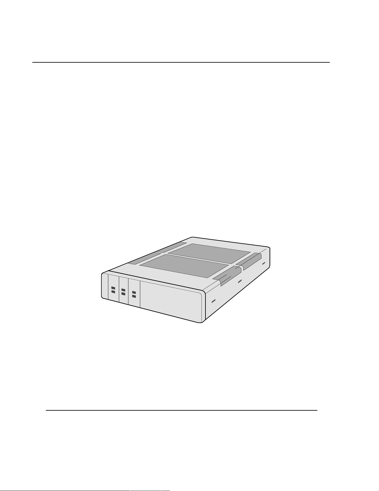
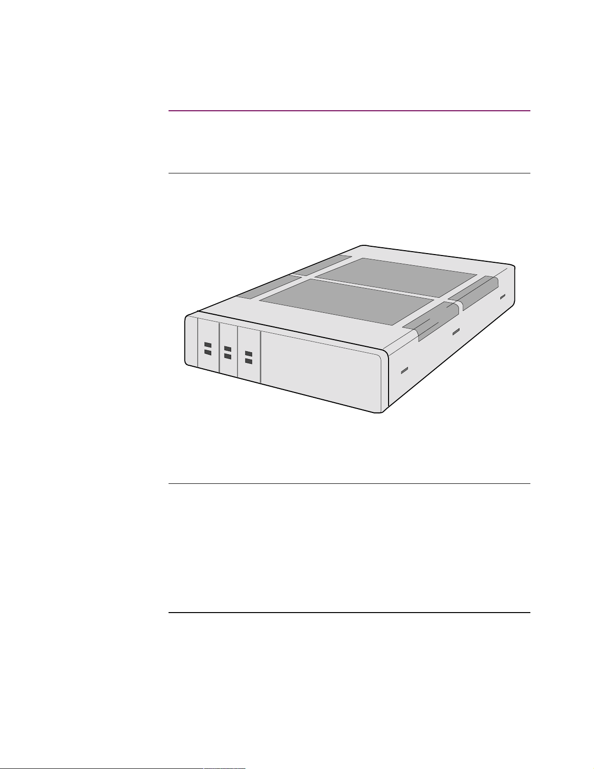
Introduction The Vanguard 650 Series, shown in Figure 1-1, is a low-cost, ISDN terminal adapter
designed to address retail applications requiring D-packet support for Point Of Sale
(POS), lottery, and alarm system protocols.
S
T
A
T
U
S
T
E
S
T
P
W
I
S
D
N
-
D
P
R
O
T
S
1
P
6
O
T
5
S
2
0
Figure 1-1. Vanguard 650 Series
In This Chapter Topic See Page
Vanguard 650 Series Features ...................................................................... 1-3
Sample Network Topology ........................................................................... 1-4
651/653 - Data Only ..................................................................................... 1-5
652/654 POTS With/Without Battery Backup ............................................. 1-6
652/654 With POTS Support ................................................................... 1-7
652/654 With POTs and Battery Backup ................................................. 1-8
Hardware ...................................................................................................... 1-10
Detailed 650 Series Front Panel ................................................................... 1-11
Detailed 650 Series Rear Panel .................................................................... 1-13
Software ........................................................................................................ 1-14
Getting Started 1-1
Page 16

Configurations The Vanguard 650 Series currently comes in four hardware configurations:
• 651 - Data only without internal modem or battery. This model comes with
2 serial ports and one ISDN U interface port.
• 652 -Data and Plain Old Telephone System (POTS). This model comes with
(or without) battery backup, an internal modem, and is equipped with 2 serial
ports, 2 POTS ports, and one ISDN U interface port.
• 653 - Data only without internal modem or battery. This model comes with
2 serial ports and one ISDN S/T Interface port.
• 654 - Data and Plain Old Telephone System (POTS). This model comes with
(or without) battery backup, an internal modem, and is equipped with 2 serial
ports, 2 POTS ports, and one ISDN S/T interface port.
What Is the 650? Unlike a traditional ISDN Terminal Adaptor, the Vanguard 650 Series is known as an
ISDN PAD (Packet Assembler/Disassembler). Although it has the same functionality
as standard TA’s for POTS support, it handles data differently. The 650 product has
an internal X.25 switching PAD, and can route data traffic across the ISDN D packet
channel. As a result, multiple applications can be supported on a single ISDN basic
rate (2B+D) link while freeing up the two B channels for true voice, modem, or fax
calls.
Supported
Protocols
The Vanguard 650 Series of products provides full support for protocols such as
SDLC, Bisync, Burroughs Poll Select, 2260, ALC, and 3201. (See the Software
Advisory Notice for the currently shipping software release for a full list of supported
protocols and features.) This product also provides support for local termination
(Poll Spoofing), and switching.
1-2 Getting Started
Page 17

Vanguard 650 Series Features
Vanguard 650 Series Features
Standard Features These products offer the following standard features:
• Small profile
• U or S/T ISDN Interfaces
• Full X.25 PAD and Switch support
• SNMP management and Telnet/X.28 control port support
CTP Data Port 2, a DB25 connector configured as a DCE interface, is used as the CTP for
configuration, reporting, and troubleshooting the 650 Series. To access the CTP you
must configure your terminal emulation software to VT100, 9600 bps, 8 bit, no
parity, 1 stop bit.
ISDN Service The Vanguard 650 Series provides an Integrated Service Digital Network Basic Rate
Interface (ISDN BRI) which, via a connector that supports both RJ11 (ISDN U) and
RJ45 (ISDN S/T), offers access to ISDN networks. A substantial set of protocols are
supported over ISDN.
Multiprotocol
Support
Software Download Chapter 3, Installing and Coldloading 650 Series Software, provides complete
RFC 877 RFC 877 encapsulation of IP datagrams over an X.25 network allows for
Support includes SDLC, Bisync, X.25, Async, IP/IPX, and PPP, as well as many
other serial protocols. Refer to the Software Release Notice which accompanied your
unit for a complete listing of protocols supported by the Vanguard 650 Series.
Vanguard 650 Series downloading and coldloading instructions.
interoperability of Front End Processors (FEPs) that support X.25 and IP traffic as
well as router vendors supporting RFC 877/1356.
Getting Started 1-3
Page 18
Sample Network Topology
Sample Network Topology
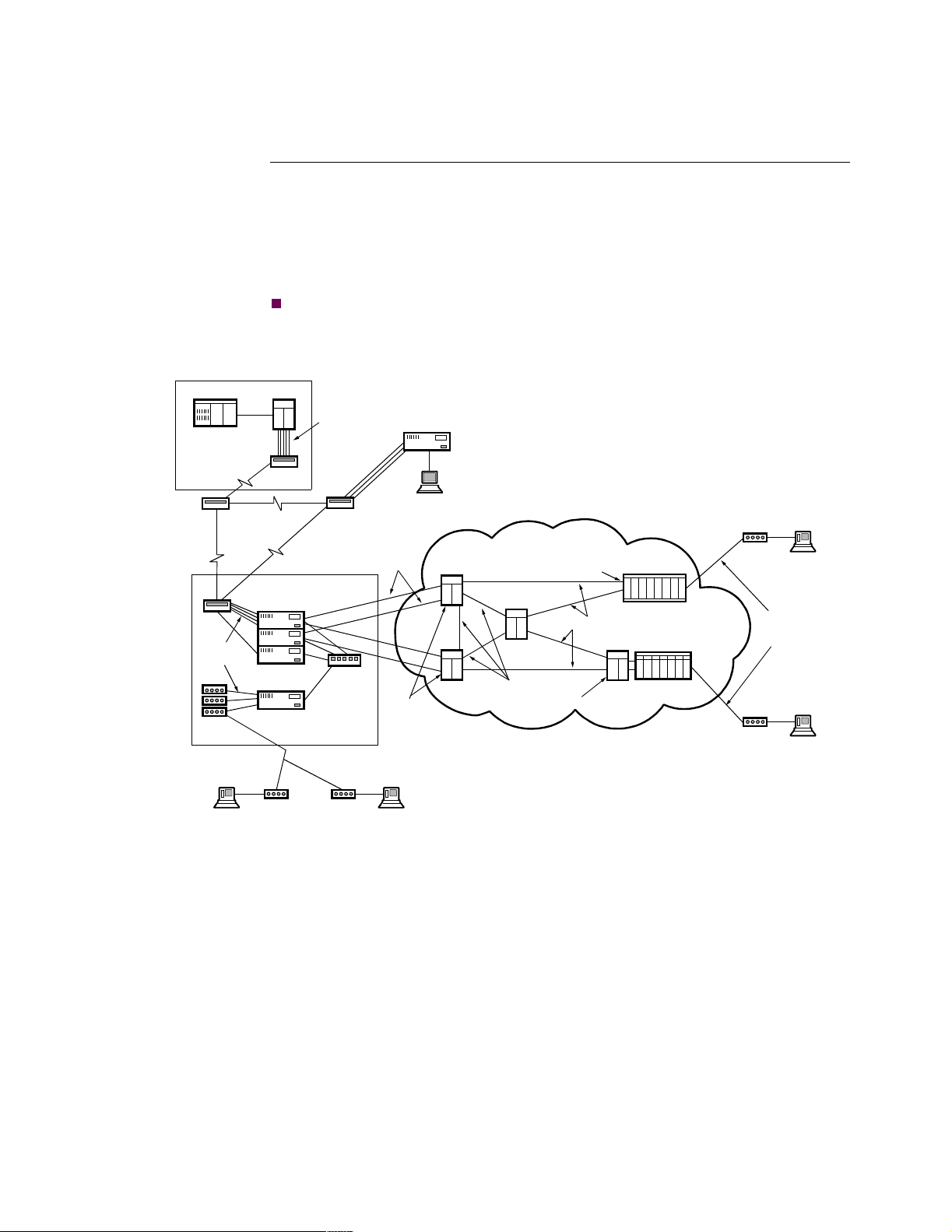
Introduction Figure 1-2 shows a sample network topology for the Vanguard 650 Series. This
example, depicting a State Lottery network, shows the connection for the DMS-100
ISDN switch. The example assumes that the Lottery Terminal has a 202T four-wire
interface communicating at 1800 or 2400 bps. If the interface required is V.24, then
you would configure Port 3 and set the soft switch parameter in the Node Record to a
value of NONE.
Note
Note that the remote 650D does not initiate calls in this example.
Lottery Host
Site (2)
Timep lex
TDM
X.42
Protocol
Analog/Conversion
Multiple
Modems
Lottery Terminal
(Non-ISDN Lines)
FEP
X.42
Protocol
Tim eple x T DM
56Kbps X.25 Circuits
Maximum 2 per 6250
180 Logical Channels
Distribution Node
Facility
Managed
Units
Modem
Modem
Network Management
Access Point for
HP OpenView
Network
Management
Station (2)
per Circuit
Hub
DPN X.25
Switches with
Switch Module and
Resource Modules Minimum of 2 per LATA
Lottery Terminal
(Non-ISDN Lines)
ISDN/X.25 Network One per LATA
SESS Packet Handler
DPN Access
Concentrator
Intermodel
Trunks
X.75 Circuits ISDN to X.25 Handoff
DMS Packet Handler
SESS ISDN Switch
DMS-100 ISDN
Switch
Vanguard 652D's
Terminal
Multiple
28= ISDN BRI
Lines
Vanguard 652D's
Terminal
Lottery
Lottery
Figure 1-2. Sample 650 Network Topology
1-4 Getting Started
Page 19

651/653 - Data Only
651/653 - Data Only
Introduction The 651 and 653 are 68302 microprocessor based devices cable of transmitting data
only. Both are shipped with 1MB of DRAM and 1.25MB of Flash memory, and
have:
• an ISDN (RJ-45) connection; the 652 is a U interface and the 654 is S/T
• two serial data ports; one async/sync V.24 interface with a DB25 connector,
one async/sync V.24 with an RJ45 connector.
External Designation Connector Type Internal CTP
Designation
DATA 1 RJ45 Port 2
DATA 2 DB25 Port 3
Note
This RJ45 serial data port is also used to connect to the integral 202/212
(V.23/21) modem. Power is supplied via an external DC power supply.
Getting Started 1-5
Page 20

652/654 POTS With/Without Battery Backup
652/654 POTS With/Without Battery Backup
Introduction The 652 and 654 are 68302 microprocessor-based devices capable of transmitting
data and voice. Both are shipped with 1MB of DRAM and 1.25MB of Flash
memory, and have:
• an ISDN (RJ-45) connection; the 651 is a U interface and the 653 is S/T.
• two serial data ports; one async/sync V.24 interface with a DB25 connector,
one async V.24 with an RJ45 connector.
• two POTS ports
Note
This RJ45 serial data port is also used to connect to the integral 202/212
(V.23/21) modem. Power is supplied via an external DC power supply.
External Designation Connector Type Internal CTP
Designation
DATA 1 RJ45 Port 2
DATA 2 DB25 Port 3
1-6 Getting Started
Page 21

652/654 POTS With/Without Battery Backup
652/654 With POTS Support
Introduction The 652 and 654 offer the added feature of North American POTS (Plain Old
Telephone System) support via 2 POTS port (RJ11) connections. This means your
Vanguard 650 Series can handle both voice and data requirements from a single unit.
Types of
Equipment
Supported
POTS Support
Guidelines
You can connect the following equipment to 652/654 POTS ports:
• Standard DTMF
• Answering machine
• Modem
• Group 3 Facsimile machine
• The 652/654 supports only good quality telephone equipment. Contact your
local Vanguard sales representative for details on supported equipment.
• 652/654 POTS ports are intended for use with telephone equipment only. 652
POTS ports are not intended to drive existing house wiring for telephone
service. They are intended for use with standard desktop telephone
equipment, and should not be connected to publicly regulated analog lines.
• Each 652/654 POTS port supports a Ringer Equivalence (REN) of two. This
means the total REN of telephone equipment connected to each port cannot
exceed two. Standard telephone lines have a REN close to one. Modems,
facsimile machines, and main powered telephones may have a REN of 0.2.
Therefore, you can connect from two to four devices to each POTS port,
depending on the type of telephone equipment you are operating.
• Each POTS port is connected to the other. The main line, marked as such on
the backplane, is connected between pins 3 and 4, while the second line is
connected between pins 2 and 5. This arrangement enables the connection of a
two-line telephone or an extension of both ports with a single four-wire cable.
Note
Some modems and telephones may use pins 2 and 5 for purposes other than
connecting to a second line. Make sure the telephone equipment connected to the
POTS port is a two-lead cable.
Getting Started 1-7
Page 22

652/654 POTS With/Without Battery Backup
652/654 With POTs and Battery Backup
Rechargeable
Battery Pack
Operation On
Battery Backup
Recharging Battery
Pack
Replacing
Batteries
The 652 and 654 devices are also available with a 12 volt rechargeable battery
backup pack. This pack consists of ten 1.2 volt NiCd battery cells in a metal carrier.
This enables these units to support POTS and ISDN operation during power failures,
for approximately 2.5 hours of normal telephone use. If both POTS ports are in
continuous use during battery operation, the useful time drops to approximately 1.5
hours. Battery operating time (capacity) is also dependent on the temperature;
battery capacity decreases as temperature increases.
To reduce power consumption, during battery operation, the data and modem ports
will not operate. When the battery is in operation, the power LED flashes.
The electric power plug, which connects to the external wall-mounted power supply,
acts as a battery switch. When the power supply transformer is plugged in, the
battery is connected to the circuit, and vice versa.
A completely discharged battery pack takes about 14 to 16 hours to fully recharge.
The charging circuit activates every time the unit powers up. After 16 hours of
operation, the charging circuit reduces the current to the batteries to a trickle charge
level to prevent overcharging.
The batteries are shrink wrapped around a metal carrier, installed inside the unit on
the Printed Circuit Board (PCB). A pair of wires connects the battery pack to a
connector on the PCB. The connector is keyed to prevent inserting the connector the
wrong way and reversing the order of the battery pack.
To replace the battery, perform the following steps:
Step Action
1 Remove the unit’s cover.
2 Remove the battery connection from the PCB.
3 Remove the screws on the bottom of unit that hold the battery pack in
place.
4 Remove the battery pack.
5 Install a new battery pack by performing these steps in the reverse
order.
Battery Disposal Please contact the Rechargeable Battery Recycling Corporation (RBRC), at one of
the following telephone numbers, for specific information on the safe disposal and/or
recycling of rechargeable batteries.
• Individual Household Batteries:1-800-822-8837
• Retailers Disposal:1-770-984-0708
1-8 Getting Started
Page 23

652/654 POTS With/Without Battery Backup
Storing the 652
With Battery
Backup
Note to Users of
Other Network
Access Products
When storing the 652 or 654, disconnect the power cord from the unit and the
electrical outlet. The power cord acts as a battery switch. As long as the power cord
is connected to the unit, the battery is connected to this circuit. Remove the plug
from the unit to disconnect the battery from the circuit.
There are a number of significant differences between the operation and
functionality of 650 Series products and other Network Access products in the 65xx
and Vanguard lines. These differences include the following:
• Operating software is divided into two distinct segments: base software and
option images. This is discussed in detail in Chapter 3, Installing and Coldloading 650 Series Software.
• TFTP functionality is partially enabled by Software Access Key (SAK). The
SAK’d portion is the ability to perform a base software download via remote
TFTP server.
• Flash-to-flash transfer is not operational on a 650 Series products.
• The system clock resets to a default value after a power failure.
Getting Started 1-9
Page 24

Hardware
Hardware
Introduction This section describes Vanguard 650 Series hardware components.
651/653 Hardware
Components
652/654 Hardware
Components
Vanguard 651 and 653 units include the following hardware components:
• A motherboard with 68302 processor
• An external power supply
• One ISDN U (651) or S/T (653) port with cable
• One CTP/Data Port
Vanguard 652 and 654 units include the following hardware components:
• A motherboard with 68302 processor
• An external power supply
• One ISDN U (652) or S/T (654) port with cable
• Two POTS Ports
• One CTP/Data Port
1-10 Getting Started
Page 25
Detailed 650 Series Front Panel
Detailed 650 Series Front Panel
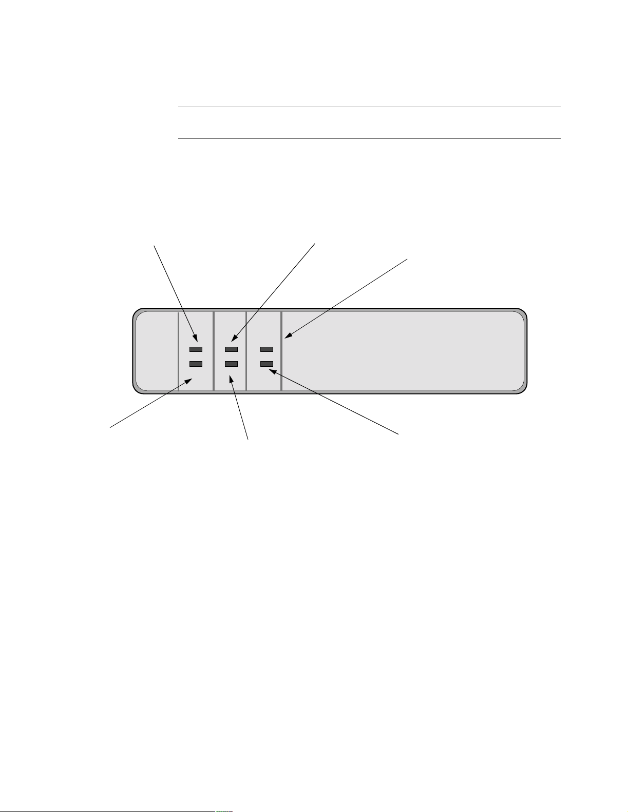
Introduction The 650 front panel provides indicators that let you monitor your equipment.
Front Panel Figure 1-3, and Figure 1-4 show the front panel of the 650.
Status
On: Software running.
Off: Software not running.
Flashing: Software running and
ISDN-D
On: On if successful commu-
Off: Off if the ISDN is inactive
(Hardware Fault)
download in progress.
nication is established.
or is disconnected.
STATUS TEST
ISDN-D POTS1
Tes t
Indicates status of test results.
• On: Test failed.
• Off: Normal condition.
• Flashing: Test in progress.
PWR
650
POTS2
POTS1
Indicates POTS1 or POTS2 usage over B
channel.
• Off: No activity.
• Flashing: POTS 1 off hook.
• On: POTS 1 call connected or
B channel data call
connected on Port 2.
PWR (Power)
On: Power is on and all DC Voltages
are within specifications.
Flashing: The unit is operating on Battery
POTS2
Indicates POTS2 usage
power.
• Off: no activity.
• Flashing: POTS 2off hook.
• On: POTS 2call connected or
B channel data call connected.
Figure 1-3. 650 Front Panel LED’s
Getting Started 1-11
Page 26

Detailed 650 Series Front Panel
y
Status
On: Software running.
Off: Software not running.
Flashing: Software running and
(Hardware Fault)
download in progress.
ISDN-D
POTS 1
Note
POTS 1 and POTS 2 are
on the 652 and 654
models onl
.
Tes t
Indicates status of test results.
On: Test failed.
Off: Normal condition.
Flashing:Test in progress.
Power On:
Power is on and all DC
Voltages are within
specifications.
POTS 2
Figure 1-4. 650 Front Panel Switches
ISDN S/T Interface
Switch - on 653 and
654 models only.
653/654 Front
Panel DIP Switches
The four DIP switches on the front panel are defined below:
Switch
Position
Switch Name Open /Down
(1)
Closed/Up (0)
1 ISDN S/T 100 Ohms
2 Not Used - - - -
3 Not Used - - - -
4 Not Used - - - -
1-12 Getting Started
Page 27

Detailed 650 Series Rear Panel
Detailed 650 Series Rear Panel
650 Connectors The 650 back panel provides the following network connectors.
ISDN Cable
RJ45
ISDN U
Data 1
651/653 Series Back Panel
DB25
Data 2
ISDN U
RJ45
POTS 1 POTS 2
Data 1
652/654 Series Back Panel
Power
Telephone Cables
DB25
Data 2
Power
Power Supply
Figure 1-5. 650 Series Rear Panel Connectors
Getting Started 1-13
Page 28

Software
Software
Introduction This section briefly describes the operating software for Vanguard 650 Series
devices.
Operating Software The operating software comes in three formats: Base, Boot, and Option. There are a
variety of operating software images available for the Vanguard 650 Series. See the
Software Release Notice accompanying your product for feature information on
available operating software. See the “Installing Software” section in Chapter 3 for
information on installing the operating software.
Optional Feature
Software
Enabling a SAK When you purchase a software option, you receive a 20-character Software
Some options purchased for the Vanguard 650 Series require a Software Access Key
(SAK). The SAK enables software options and, if you have purchased an option
requiring it, the SAK will be identified on a SAK Acknowledgment Sheet, see
Figure 2-1.
If you are required to enter a SAK refer to the following sections.
Authorization Key (SAK) to enable the option. The SAK corresponds to the serial
number of your Vanguard 650 Series, so it cannot be used on any other node. To
enter the SAK key:
Step Action
1 Select Configure ->Software Key Table from the CTP Main menu.
2 At the Entry prompt, select a new entry. Make sure you do not overwrite
existing SAK entries.
3 At the Key Value prompt, type in the 20-character code followed by a
semicolon (;) to save the SAK.
4 Boot the node.
1-14 Getting Started
Page 29

Software
Examining a SAK To view the software options installed on your Vanguard 650 Series, select the
Software Option Statistics from the CTP Main menu. Figures 1-6 and 1-7 show
typical software option screens for a 650.
Node: New Address: (blank) Date: 1-MAY-1997 Time: 0:00:00
Software Option Stats Page: 1 of 2
Software Options maximum allowed used
========================= =============== ====
LINK backup ANY N/A
FR DTE Interface ANY N/A
FLASH Enable ANY N/A
Transparent Bridge ANY N/A
Enhanced LAN Option ANY N/A
FR DCE Interface ANY N/A
Ethernet LLC Conversion ANY N/A
Unauthorized Ports:
NONE
Unauthorized Options:
NONE
Figure 1-6. Software Option Statistics - Screen 1 of 2
Node: New Address: (blank) Date: 1-MAY-1997 Time: 00:00:007
Software Option Stats Page: 2 of 2
Summary of Custom Sof tware Options:
Code Description
===== ============================================================
00010 X25 DTE support Enabled.
Figure 1-7. Software Option Statistics - Screen 2 of 2
Getting Started 1-15
Page 30

Page 31

Chapter 2
Installing 650 Series Hardware
Overview
This chapter covers the installation of Vanguard 650 Series hardware and cables, and
describes serial port characteristics and associated features.
In This Chapter Topic See Page
Checking Your Shipment Contents .............................................................. 2-2
Choosing a Site ............................................................................................. 2-3
Cabling the 650 Series .................................................................................. 2-4
Powering Up the Vanguard 650 Series ......................................................... 2-7
Removing the Top Cover and Front Panel ................................................... 2-8
Follow These Steps This table lists the steps you need to perform and shows you where to look for
information on installing the Vanguard 650 Series:
Step To Perform This Action See This Procedure
1 Check the contents of the ship-
ping package to make sure
everything is included.
“Checking Your Shipment Contents”
section on page 2-2
2 Choose a site for the 650 Series. “Choosing a Site” section on page 2-3.
3 Connect cables for the 650
Series.
4 Power up the 650 Series “Powering Up the Vanguard 650 Series”
“Cabling the 650 Series” section on
page 2-4.
section on page 2-7.
Installing 650 Series Hardware 2-1
Page 32

Checking Your Shipment Contents
Not
Checking Your Shipment Contents
Introduction The Vanguard 650 Series of products is packaged in shock-absorbent packing
material. Inside your shipping carton, you should find the contents shown in
Figure 2-1:
S
T
A
T
U
S
T
E
S
T
P
W
R
I
S
D
N
D
P
O
T
S
1
P
O
T
S
6
2
5
0
RJ11/RJ45 Telco Connection Cable
650 Series Unit
External
Tran sformer
The External Transformer may, or may not, be
shipped with the product you order. Some
Product Codes require that this transformer be
ordered separately.
for ISDN Connection
e
Figure 2-1. Vanguard 650 Series Shipment Contents
Note
If you plan to use a personal computer to configure 650 Series software, you
may need to purchase a DB25 (female) to RJ45 (male) adapter for the serial port
of your personal computer. An optional DB25 to RJ45 cable is available for
accessing the Control Terminal Port.
Also note that 650 units currently ship with the external power supply as shown
above. Future units will incorporate a wall-mount transformer. The future
transformers will be country-specific. The transformer Product Codes are:
• 49602
Europe
• 49603
Australia
• 49604
Japan
• 49605
UK
• 49606
Domestic
2-2 Installing 650 Series Hardware
Page 33
Choosing a Site
Choosing a Site
Introduction This section describes how to choose an appropriate site for your Vanguard 650
Series hardware.
How to Choose a
Site for the
Vanguard 65x
Choose a site that is within an appropriate distance of a power source. Depending on
your application, and the country in which the Vanguard 650 Series will operate, the
power source must be a grounded 100 to 240 VAC outlet.
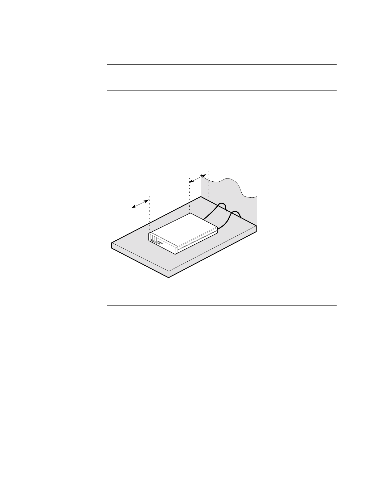
To avoid overheating the circuitry, never place anything on top of the unit. Also,
leave at least 2 inches (5 cm) of clearance in front of the front panel, to allow you to
see the unit’s LEDs, and behind the unit for interfacing cable clearance, as shown in
Figure 2-2.
The selected site should be free of accumulated dust and environmental extremes.
Minimum 2 inches (5cm)
Front and Rear
Do Not Place
Anything on Top
of Unit
Figure 2-2. Proper Cable and Air Clearance
Installing 650 Series Hardware 2-3
Page 34

Cabling the 650 Series
Cabling the 650 Series
Introduction After you unpack the Vanguard 650 Series, you can connect the cables to complete
the installation. Figure 2-3 illustrates the rear panel of the 652/654 with an ISDN
(U or S/T) interface, and shows the locations to which the various cables must be
connected. The 651 and 653 rear panels are the same, but without the two POTS
ports.
651/653 Series
Back Panel
ISDN U
(to Async Terminal)
CTP Cable
ISDN U or S/T
RJ45
Data 1
DB25
Data 2
ISDN U
POTS 1 POTS 2
CTP Cable
(to Async Terminal)
Power
Telephone Cables
RJ45
Data 1
DB25 connector
DB25
Data 2
652/654
Series Back
Power
Power Supply
DB25 connector
Figure 2-3. 650 Series Back Panel
2-4 Installing 650 Series Hardware
Page 35

Cabling the 650 Series
Caution
All Vanguard 650 Series devices should be used in environments designed for
computers and electronic equipment. In areas susceptible to lightning, take
precautions to prevent damage to electronic equipment. Contact your telephone
company, an electronic accessories vendor, or Hydro Electric operator for
information on lightning protection equipment. Customers experiencing problems
caused by surges from lightning have eliminated such problems by installing
appropriate surge suppressors on power and data lines connected to Vanguard 650
Series devices.
Cable Clearance/
Air Circulation
ISDN Cable An RJ-11 ISDN cable is supplied with your Vanguard 650 Series. The pinouts for the
Data 1 and Data 2 The Data 1 port is an RJ45 connector that can be used for a partial EIA 232 or Async
CTP Cable Optional DB25 (male) to DB9 (male) OR RJ45 to DB25 cables, for access to the
To avoid overheating the unit’s circuitry, you should never place anything on top of
the unit. It is also recommended that you leave at least 1 inch (2.5 cm) of clearance in
front of the front panel to allow you to see the unit’s LEDs, and allow at least 2
inches (5 cm) in back of the unit for interfacing cable clearance.
cable are given in the “ISDN Cable Description” section of Appendix A,
Specifications. The cable is available for the U interface (RJ11) or the S/T interface
(RJ45), and the part numbers for the cables are U:61766-02 and S/T:61545-01,
respectively.
modem connection (on the 652/654) or a partial EIA 232 Sync/Async connection
(on the 651/653).
The Data 2 port is a DB25 connector, which is an EIA 232 connection on both units.
Data 2 is also used as the physical CTP interface connector to the PC, Macintosh, or
workstation.
The pinouts for the cables used for Data 1 and Data 2 are given in the “Data 1 and
Data 2 Cable Descriptions” of Appendix A, Specifications.
Control Terminal Port, are available. The serial ports on most personal computers
require DB9 connectors.
Installing 650 Series Hardware 2-5
Page 36
Cabling the 650 Series
Changing the
Modem Strapping
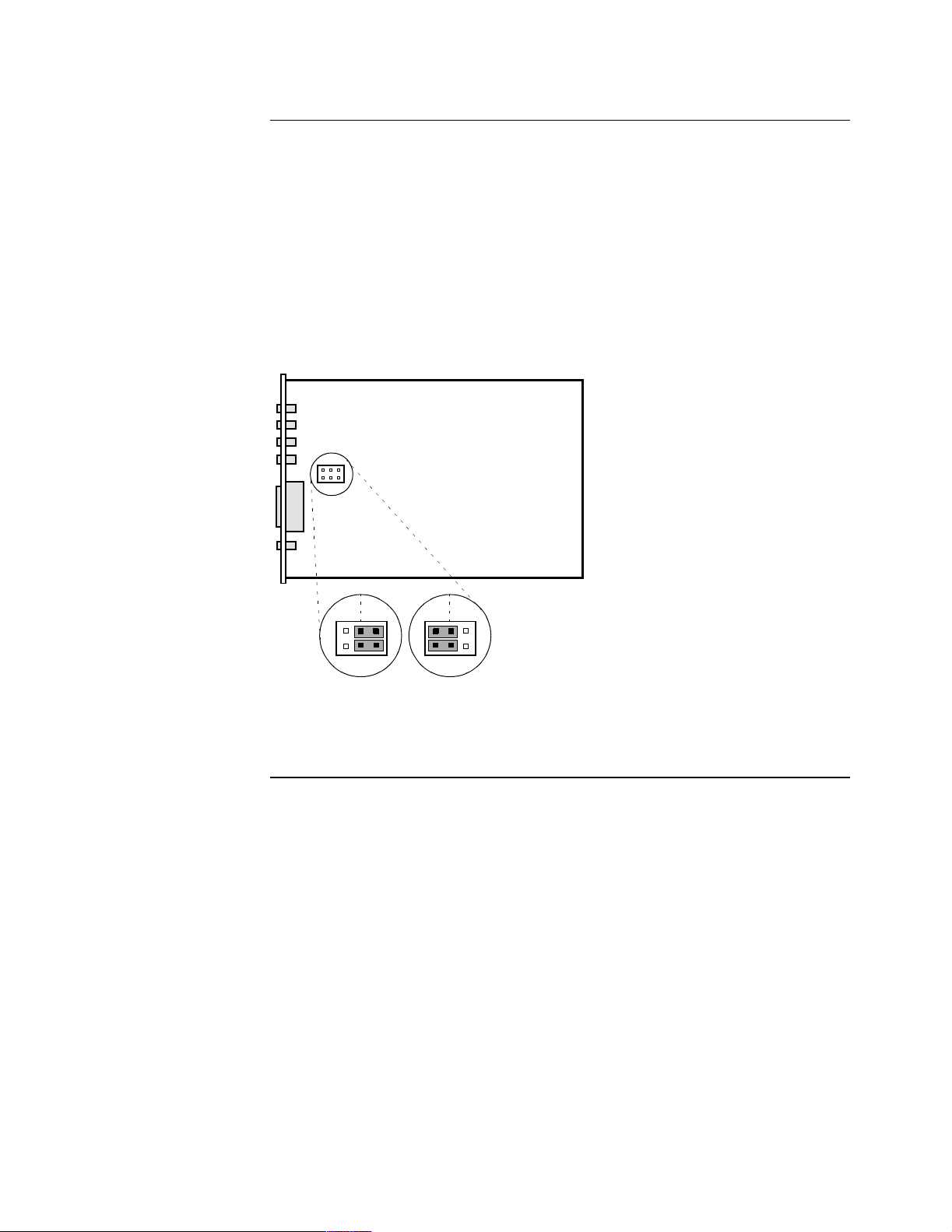
The default setting for the modem strapping is in 4-wire mode. If you need to change
the modem support from the default 4-wire position to the 2-wire mode, you must
perform the following steps:
1) Locate the J10 strap on the modem card.
2) Remove the blue jumper by sliding it up, off of the pins that specify 4-wire mode
(see Figure 2-4).
3) Carefully slide the jumper over the pins that specify 2-wire mode. The pins for
2-wire mode are to the left of the default 4-wire position when facing the card as
oriented in the figure.
Figure 2-4 shows the strapping positions for 2-wire and 4-wire modes.
2W
4W
J10
4-Wire Mode
(Default)
2W 4W
J10
2-Wire Mode
Figure 2-4. 4-Wire and 2-Wire Modem Strapping Positions
2-6 Installing 650 Series Hardware
Page 37

Powering Up the Vanguard 650 Series
Powering Up the Vanguard 650 Series
Introduction This section describes the sequence of events when you power up a Vanguard 650
Series device.
Powering Up The Vanguard 650 Series does not have a power switch on the unit. Therefore,
follow these steps to power on the Vanguard 650 Series:
Step Action
1 Plug the small round DIN type connector of the power supply into the
power socket on the Vanguard 650 Series back panel.
2 Connect the power cord into the power supply outlet.
Diagnosing Startup Failures
The front LEDs on the 650 Series (Figure 1-3) will help you to follow the progress of
the unit’s power up. The following identifies the types of failures you may encounter.
Failure Description Action
Hardware
Failure
Powerup
Failure
If the TEST light turns on and
remains on, one or more of the
diagnostic tests have failed,
indicating a hardware problem.
If the STATUS light blinks
continuously, at a constant rate,
the software bundle in Flash
memory is corrupted.
Contact Customer Support for
possible repairs to your Vanguard
650 Series products.
Perform a coldload of the
software option bundle.
Installing 650 Series Hardware 2-7
Page 38
Removing the Top Cover and Front Panel
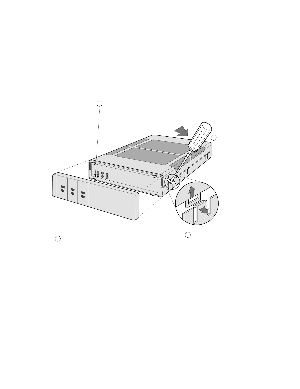
Removing the Top Cover and Front Panel
Before You Begin Power down and disconnect the 650 Series before removing the top cover, front
panel, or any components.
Cover and Front
Panel Removal
S
T
A
T
U
S
T
I
S
D
N
-
D
P
O
T
Figure 2-5 shows you how to remove the top cover and front panel.
Remove the front panel by snapping panel
1
from tabs.
Open this panel by pulling the panel
forward on its hinge.
E
S
T
P
W
R
S
1
P
O
6
T
S
5
2
0
Insert a screwdriver at a
2
45° angle on one of the six
release hinges and push
downward.
3
Repeat for all six hinges.
4
Release three hinges on each side.
Figure 2-5. Opening the 650 Series
2-8 Installing 650 Series Hardware
Page 39

Chapter 3
Installing and Coldloading 650 Series Software
Overview
Introduction This chapter describes how to install and coldload operating software and
configuration memory files (CMEMs) for your 650 Series node. Please refer to the
Software Installation and Coldloading Manual (T0028) and Software Builder
Manual (T0030) for information on the use of the Vanguide Application Set and
Software Builder to create custom images and install them into your 650 Series
device.
Note
The procedures for software upgrade for a 650 Series product differs from that of
other Network Access Products. Please read the following information carefully
before initiating a software upgrade.
In This Chapter Topic See Page
650 Operating Software and Option Images ................................................ 3-2
Where to Get Operating Software ................................................................ 3-3
Installing Software ........................................................................................ 3-5
Coldloading 650 Series Operating Software ............................................ 3-6
Loading Software via TFTP Download ................................................... 3-8
Downloading Software Using the Software Loader ................................ 3-10
Downloading Configuration Memory (CMEM) ...................................... 3-14
Vanguide Terminal ................................................................................... 3-16
Linking Software Images Using Software Builder .................................. 3-18
Selecting a Predesigned Configuration ........................................................ 3-19
Selecting a Predesigned Configurations Using the CTP .......................... 3-20
Saving and Restoring Configurations Using Kermit ............................... 3-21
Saving and Restoring Configurations Using TFTP ................................. 3-23
Follow These Steps This table lists the steps to perform and shows you where to look for information
when installing operating software and CMEM files for your 650 Series device.
Step To Perform This Action See This Procedure
1 Obtain the operating software you
want to install on the 650 Series.
2 Obtain the Configuration Memory
(CMEM) file you want to install
on the 650 Series.
3 Download the operating software
and CMEM file to the 650 Series.
Installing and Coldloading 650 Series Software 3-1
“Where to Get Operating Software”
on page 3.
“Where to Get Operating Software”
on page 3.
“Installing Software” on page 5.
Page 40

650 Operating Software and Option Images
650 Operating Software and Option Images
Introduction There are three software segments to the 650 operating software:
•Base software
• Boot PROM
• Option images
Each of these segments can be independently downloaded, allowing you to change
your option package without having to disrupt your base software. However, you
must ensure that both the base software and option image are from the same software
release. If they are not, only the base software will be loaded.
Base software provides the 650 Series device with the minimum set of operational
code required to allow the device to become functional, i.e., ready to receive an
option image. The option image provides the remaining functionality to make the
unit fully operational.
Base Software Base software names can range from image number 1 to 19, and option images can
range from 20 to 89.
The base software segment contains the minimum software required to render the
unit operational and able to receive an additional option image software via TFTP.
Base software minimally contains the following functionality: X.25, Telnet, SIP, and
a choice of the type of ISDN support you require (North American, European, or
Asian).
The following base software is available for the 650 Series:
Image Filename
5.0 North American ISDN 500i01.zip
5.0 European ISDN 500i02.zip
5.0 Asian ISDN 500i03.zip
Boot PROM The following Boot PROM image is available for the 650 Series:
Boot PROM Filename Description
5.0 500i00.zip This should not be required. Check the
Software Release Notice for your
software version for appropriate
instructions.
Option Images To accommodate a variety of customer applications, there are multiple software
option images, with various supported protocols, available for the Vanguard 650
Series.
If your specific application requires a different option set than you currently have
running, refer to the Software Release Notice accompanying your Vanguard 650
Series device to determine the software image that matches your specific needs.
3-2 Installing and Coldloading 650 Series Software
Page 41

Where to Get Operating Software
Where to Get Operating Software
Where to Get
Operating Software
Operating Software
File Formats
If you have access to the Internet, go to this URL to obtain Vanguard 650 Series
software images:
http://www.vanguardms.com
At this location, you will find the releases of software, associated software release
notices, and other information concerning products and services.
Operating software is also available on the Vanguide 5.1 CD-ROM. Please contact
your local service representative for updated information on the latest software
version.
Operating software files on the Vanguide 5.1 CD-ROM and the World Wide Web
adhere to the following file naming formats:
Software Filename Description
Base Software 500i01.xrc where:
• 500 = the software release number.(In
this case the full release number is 5.0.)
• i = identifies the file as a 650 software
image
• 01 = identifies the file as option #01.
Base software names range from image
number 1 to 19.
• .xrc = identifies the file as a software
image
500i01.zip is a compressed version of the
file.
Note
The 650 Series is shipped with base
software already installed. Therefore,
you should only need to re- install this
software when upgrading to a new
release, or to replace corrupted base
software.
Boot PROM 500i00.zip Generally speaking, this should not be
required. Check the Software Release
Notice for your software version for
appropriate instructions.
Installing and Coldloading 650 Series Software 3-3
Page 42

Where to Get Operating Software
Software Filename Description (continued)
Option Image Name:
21 Reno
500i21.zip • 500 = the software release number.
• i = identifies the file as a 650 image
• 21 = identifies the file as option #21.
Option image file names range from
image number 20 to 89
Note
The 650 Series is shipped with a default
option image installed. Therefore, you
should only need to re-install an option
image if changing the optional
functionality or protocol support you
require.
3-4 Installing and Coldloading 650 Series Software
Page 43

Installing Software
Installing Software
Introduction This section describes software installation in the Vanguard 650 Series of products.
How To The methods for installing software to your Vanguard 650 Series are:
• using a local coldload
• via a TFTP server
• using Software Loader
• using Software Builder
Note
Refer to the Vanguard Software Builder Manual (T0028) for specific
information on the use of Builder. This manual can be found on the World Wide
Web a t:
http://www.vanguardms.com
When loading a new release of 650 operating software, always load the Base
Software, and then the Option Software Image. Do not load the Boot PROM unless
the software release notice applicable to the release you are using specifically
instructs you to do so.
Vanguide
Application Set
Vanguard Software
Builder
Note
You must have a copy of a software image provided from your local service
representative, the World Wide Web, or the Vanguide 5.1 CD. Select the method
of download and follow the appropriate procedure from this section.
If you are using a PC running the Windows® operating system (NT, 95, 3.1/3.11)
with Vanguide 5.1 CD-ROM, Vanguide is the recommended means of installing
operating software and image options in your 650 Series.
The Vanguide® Application Set provides an easy-to-use Graphical User Interface
(GUI) for downloading operating software and image options, and uploading and
downloading configuration memory for the 650 Series.
The Vanguard Software Builder application lets you create custom software images
for all products, to suit your network requirements.
Note
You can not create a Software Builder image for the 650 Series using pre-5.0
released software.
This application is only available on the Vanguide Plus 5.1 CD-ROM and operates
under Windows® operating system (NT, 95, OS/2, 3.1/3.11, and SoftWindows 95).
With Vanguard Software Builder you can:
• Select specific software releases
• Customize a name and 2-digit number for the image options you want to
create
• Follow a series of command prompts to select required features/protocols to
be included in your images
Installing and Coldloading 650 Series Software 3-5
Page 44

Installing Software
Not
Coldloading 650 Series Operating Software
Introduction There are three methods for downloading new operating software to your Vanguard
650 Series: using a local coldload, via a TFTP server, or using the Software Loader
on the Vanguide 5.1 CD-ROM.
When loading a new release of 650 operating software, always load the Base
Software first and then the Option Software Image.
Coldloading
Software
If you intend to download both base software and an optional image, we recommend
that you download your Base software first.
Ensure that the software you wish to download resides on the software host that you
are using, and obtain the filename. Connect the software host’s modem serial port
directly to the 650 node data port 2.
Note
Coldloading is a procedure used to load operating software via a physical
connection between the PC, Macintosh, or workstation (software host)
containing the coldload files and the 650 node.
Step Action Response
1 Access the control port and select
Update Software from the main
The Update Software menu
appears.
menu.
2 Select Coldload. The prompt Prepare for Coldload
and Boot Node? (y/n): appears.
3 Enter
Y to initiate the coldload
procedure.
The node goes into coldload mode,
which is indicated by the Status
LED blinking at a steady rate.
4 Use your communications pack-
age (set to 8 bit, no parity, 9600
bps, 1 stop bit) to send the coldloader file in RAW ASCII mode.
e
There are different coldloader files
for different Vanguard 650 Series
models. You must use the correct
This takes approximately 10-15
seconds, and the status LED
flashes irregularly. Once the
coldloader file is loaded, the node
is immediately ready for the next
file (base software or option
image). The status LED should be
off.
one.
Vanguard 650 Series coldloader
files use this naming convention:
c650isss.xrc
where sss indicates the speed. The
speeds available are 9600, 19200,
57600, and 115200.
3-6 Installing and Coldloading 650 Series Software
Page 45

Installing Software
Step Action Response (continued)
5 Set your communications package
to the same speed as the coldloader
you just downloaded, and use
RAW ASCII mode to send the
desired image.
6 Set your communications package
back to the previously configured
speed, and reaccess the CTP.
Depending on the image you are
downloading, and the speed
chosen, this takes 3-30 minutes to
complete, and during the procedure
the LED flashes regularly,
depending upon the download
speed. The node boots
automatically at the end of the
download procedure.
If base software is loaded and
operational, the node restarts with
no further intervention.
If base software is not present in
the node, the 650 returns to
coldload mode and waits to receive
base software.
The OK prompt appears, and your
new software image is loaded.
Installing and Coldloading 650 Series Software 3-7
Page 46

Installing Software
Loading Software via TFTP Download
Introduction Trivial File Transfer Protocol (TFTP) is the Internet standard protocol for file
transfer. TFTP transfers software images without regard to content. It provides
packet sequencing to ensure proper delivery order, and uses checksum to ensure data
integrity.
Before You Begin If you are using TFTP to download either Base or Boot PROM, software, you must
have purchased the factory installed SAK for this feature. If you are using TFTP to
download an option image, this SAK is not required. Refer to the “Enabling a SAK”
section in Getting Started for additional information.
If you intend to TFTP download both base software and an optional image, we
suggests that you download your optional image first.
Note
The software download operation is not destructive to the current operating
software until the new software image begins loading (i.e., it does not
immediately corrupt the Flash memory). This means that, if the download is
interrupted for any reason, the node can return to its present operating condition.
Ensure that the software you wish to download resides on the TFTP server, and
obtain the filename. Also obtain the IP address of the server. PING the node to verify
that you have IP connectivity between the TFTP server and the 650 node.
Step Action Response
1 Access the control port, and select
Update Software from the Main
menu.
The Update Software menu
appears.
3-8 Installing and Coldloading 650 Series Software
Page 47

Installing Software
Step Action Response (continued)
2 Select TFTP. If your node is ready for TFTP
download, the following message
appears:
Optional Software Images are
DISABLED. The node is ready for
TFTP transfer.
The prompt “Network Load an
Image? (y/n):” appears. You can
then proceed to step 3.
If your node is NOT ready for
TFTP download, the following
message appears:
Optional software Images must be
DISABLED.
A node boot is required.
Disable and Boot? (y/n):
Respond to the question by
pressing the Y key.
After this, the node with
automatically reboot, and you must
return to step 1.
3 Enter Y to begin the download of
either base software or an image
The prompt Enter File Name:
appears.
option.
Enter N, and proceed to step 7, if
you are enabling an option image.
4 Enter the name of the file you wish
to load on your 650.
5 Enter the IP address of the TFTP
server.
6 Enter Y to begin transfer of the
software.
7 Enter Y, when prompted with
Enable Optional Software Images?
(y/n): to enable your option image.
The IP address: prompt appears.
The prompt Ready to initiate TFTP
transfer (y/n): appears.
The 650 automatically reboots
when the base software download
is complete. A reboot is not needed
if you are loading an option image.
Then, return to step 1 to either load
an option image or enable an
image that was previously loaded.
The node automatically reboots,
and the new option image is
enabled.
Installing and Coldloading 650 Series Software 3-9
Page 48

Installing Software
Downloading Software Using the Software Loader
Introduction The Software Loader is part of the Vanguide Application Set and is available on the
Vanguide 5.1 CD.
Follow These Steps This table identifies the steps to download CMEM files into a Vanguard 650 Series
device.
Access the Vanguide Application Manager
Vanguide
Application
Manager
Follow these steps to access the Vanguide Application Manager:
Step Action
1 Cable a personal computer containing the Vanguide application to the CTP
port of your 650 Series device to establish a physical connection.
2 Launch Vanguide from the Program group.
3 Click on the Vanguide Application Manager icon. The Vanguide
Application Manager window appears (Figure 3-1).
Figure 3-1. Vanguide Application Manager Window
Once the Application Manager window is displayed you can start device
configuration, launch the Configuration Loader or Software Loader.
3-10 Installing and Coldloading 650 Series Software
Page 49
Installing Software
Vanguard Software
Loader
Follow these steps to use the Vanguard Software Loader:
Step Action
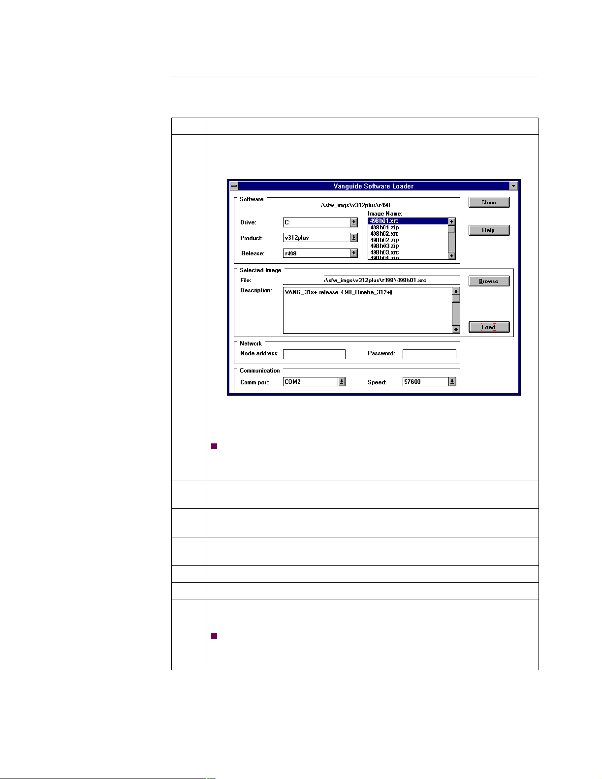
1 Click on the Software Loader button. The Software Loader window
appears.
Figure 3-2. Software Loader Window
Note
The Description box in Figure 3-2 describes the software image of a
selected filename.
2 From the Drive control, choose the disk drive that contains the operating
software images (Vanguide 5.1 CD-ROM).
3 From the Product control, choose the type of 650 Series you are loading.
This identifies the attached device.
4 From the Release control, choose the software release to download. This
identifies the software image file downloaded to the 650 Series.
5 Choose the software file to download from the Image Name dialog box.
6 Choose the COM port connected to the 650 Series CTP port.
7 From the Speed pulldown menu, choose the speed at which to download
files.
Note
To download at speeds greater than 19 kbps, your COM port must
support transfers at high speeds. Refer to online Help for more details.
Installing and Coldloading 650 Series Software 3-11
Page 50

Installing Software
Step Action (continued)
8 Click the Load button. The Software Loader prompts you to verify the
download operation.
Figure 3-3. Software Loader Verification Dialog Box
9 Click Yes to download the selected software image file to the 650 Series
device. A Status box (Figure 3-4) is displayed.
Figure 3-4. Software Loader Status Box
Or:
Click No to cancel the download operation.
3-12 Installing and Coldloading 650 Series Software
Page 51
Installing Software
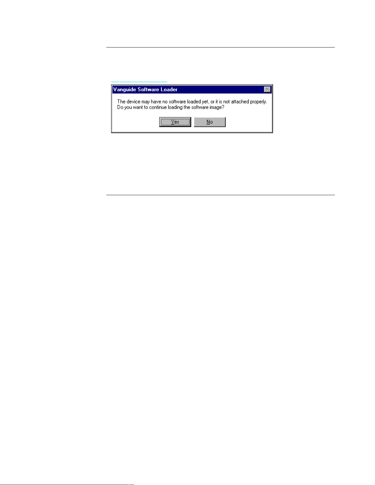
Software Loader
Error
The error message box shown in Figure 3-5 appears if the application cannot detect
the attached device. The application may be unable to detect the attached device for
one of two reasons: incorrect connections, or the device is already in the coldload
mode.
Figure 3-5. Vanguard Software Loader Error Message Box
If you receive the error message box, perform one of these steps:
• Check connections for the communication port you selected and restart the
process, or
• Verify that the status LED is flashing on the device and click Y proceed.
Installing and Coldloading 650 Series Software 3-13
Page 52

Installing Software
Downloading Configuration Memory (CMEM)
Vanguard
Configuration
Loader
Vanguard
Configuration
Loader
Use the Vanguard Configuration Loader to quickly and easily download a
preprogrammed CMEM file to your Vanguard 650 Series.
Configuration Loader also lets you retrieve CMEM files from a Vanguard 650 Series
device and save them as backups on a local disk. Refer to the Configuration Loader
online Help for details on saving and restoring CMEM files.
The Configuration Loader automatically performs a node boot after downloading a
CMEM file to a Vanguard 650 Series device to implement the new CMEM.
This table contains the steps to use the Vanguard Configuration Loader.
Step Action
1 Click Configuration Loader, from the Vanguide Application Manager
window. The Configuration Loader window appears (Figure 3-6).
Figure 3-6. Configuration Loader Window
2 From the Drive control, choose the CD-ROM drive that contains the
preprogrammed CMEMs residing on the Vanguide 5.1 CD-ROM.
3 From the Product control, choose the type of 650 Series you are loading
with CMEM. This identifies the type of 650 Series device attached to the
PC.
4 From the Application control, choose the Application set to download.
This identifies the CMEM file that downloads to the 650 Series.
5 Choose the CMEM file from the Configuration File Name box.
6 Choose the COM port connected to the 650 Series device.
7 Choose Auto-Detect to set the speed at which to download the file.
3-14 Installing and Coldloading 650 Series Software
Page 53
Installing Software
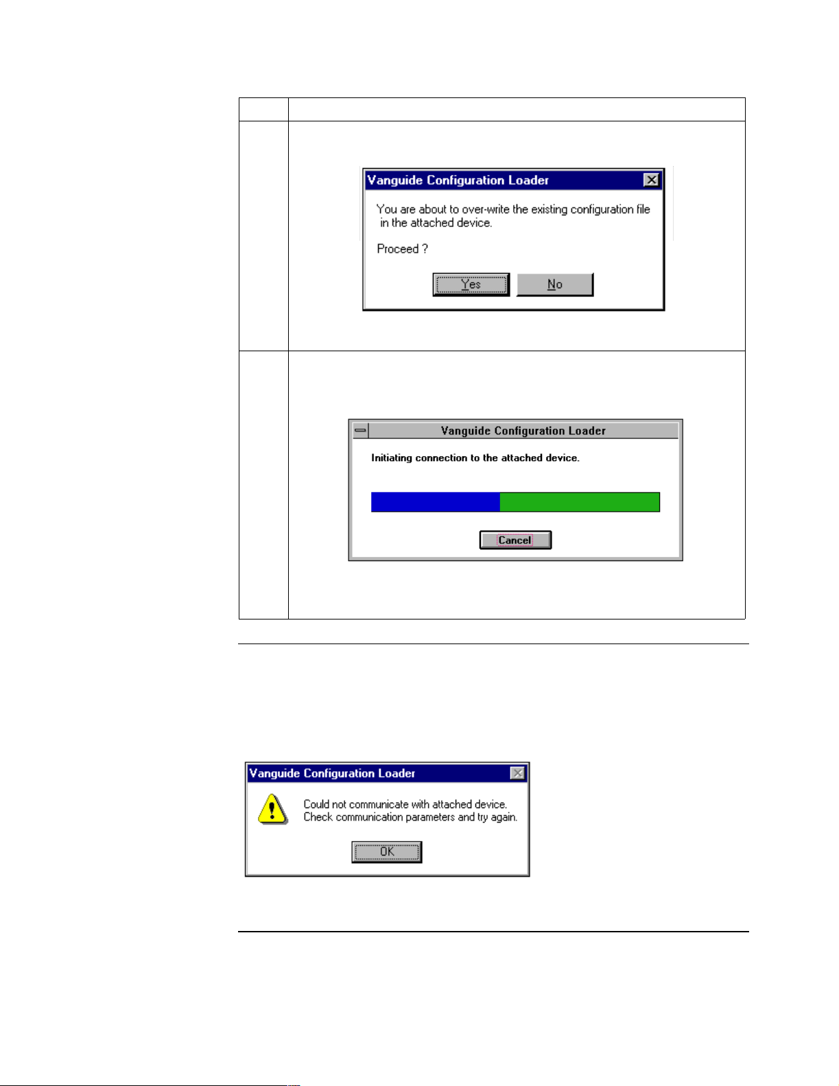
Step Action (continued)
8 Click the Load button. The Configuration Loader prompts you to verify
the download.
Figure 3-7. Configuration Loader Verification Dialog Box
9 Click Yes to download the selected CMEM file to the 650 Series device.
A status window (Figure 3-8) is displayed.
Configuration
Loader Error
Message
Or:
Click No to cancel the download operation.
The error message box shown in Figure 3-8 appears if the application cannot detect
the attached device. The application may be unable to detect the attached device
because of incorrect connections.
If the error message box appears, check the connections for the communication port
you selected and re-start the process.
Figure 3-8. Vanguard Configuration Loader Error Dialog Box
Installing and Coldloading 650 Series Software 3-15
Page 54
Installing Software
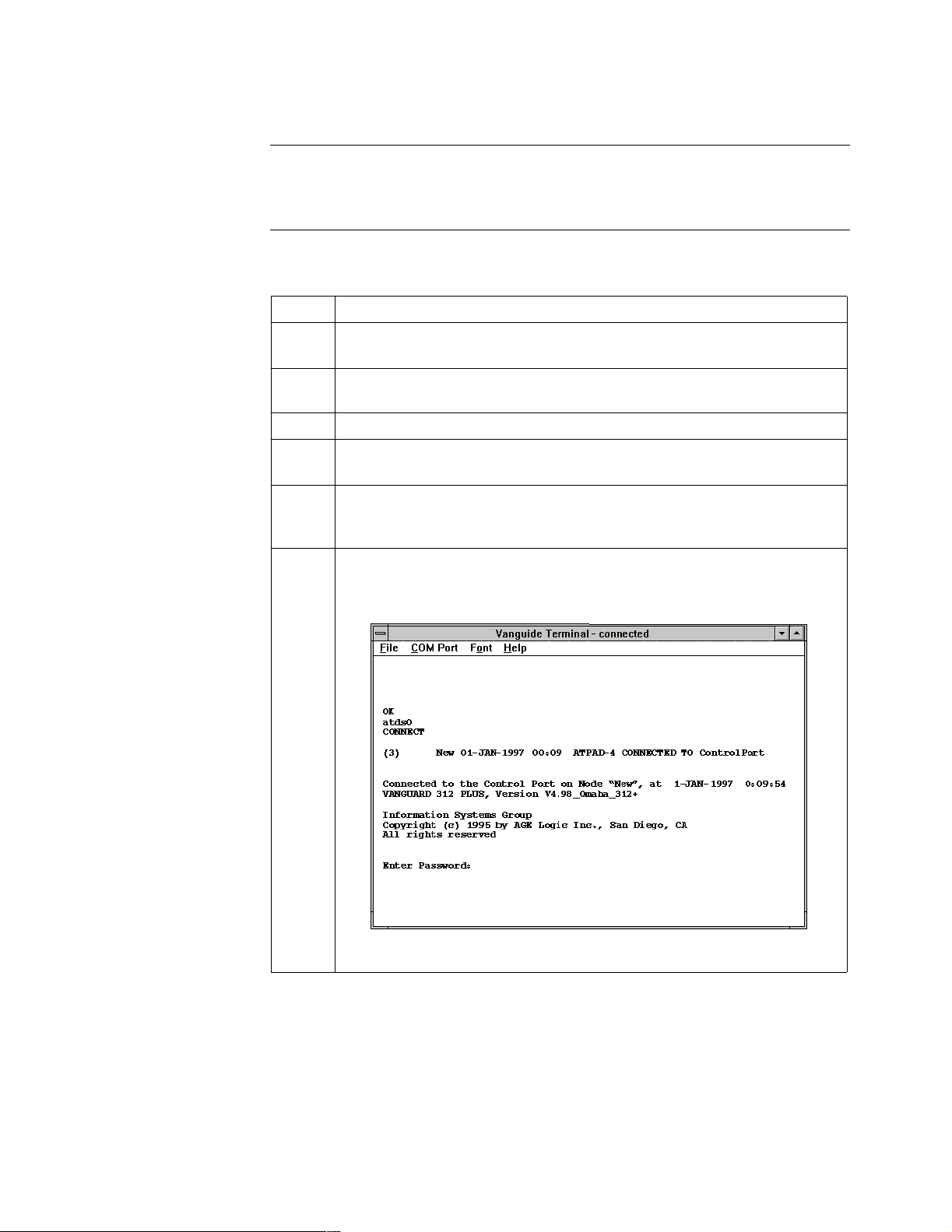
Vanguide Terminal
Overview The Vanguide Terminal (Figure 3-9) is a terminal emulator for communicating with
Vanguard devices using the CTP port. It supports basic ANSI/VT100 terminal
emulations, ignoring all escape characters for these sequences.
How To Use
Vanguide Terminal
Follow these steps to connect to a 650 Series CTP using the Vanguide Terminal
utility.
Step Action
1 Cable your 650 Series to a personal computer running the Vanguide
application, as shown in “Cabling the 650 Series” on page 4.
2 From the Windows Program Manager, open the Vanguide Application
Manager icon.
3 Make sure your Communications port is set correctly.
4 Choose Vanguide Terminal. The Vanguide Terminal window appears
(Figure 3-9).
5 Press the Return key until the OK prompt appears. This means your PC is
connected to the 650 Series. If no OK prompt appears, check the physical
connection between the 650 Series and your personal computer.
6 Enter ATDS0 and press Return. The Control Terminal Port screen
appears (Figure 3-9).
Figure 3-9. Example of Vanguide Terminal Window
3-16 Installing and Coldloading 650 Series Software
Page 55

Installing Software
Using the CTP
Main Menu
Follow these steps to use the CTP Main menu.
Step Action
1 Press Return at the Password prompt. The CTP Main menu appears, as
shown in Figure 3-10.
Node: New Address: (blank) Date: 1-JAN-1997 Time: 0:10:49
Menu: Main Path: (Main)
1. Logout
2. Examine
3. List
4. Monitor
5. Status/statistics
6. Configure
7. Boot
8. Update System Parameters
9. Copy/Insert Record
10. Delete Record
11. Port/Station/Channel Control
12. Diagnostics
13. Default Node
14. Print Configuration
15. Configuration Save/Restore
16. Flash Memory
17. LAN Control Menu
#Enter Selection:
Figure 3-10. Control Port Main Menu
2 You can begin modifying CMEM file from this menu.
The Enter Selection: prompt, appearing at the bottom of the screen,
accepts a number corresponding to the choices available in the particular
menu. (For example, to log out from the CTP, enter the corresponding
number for Logout at the Enter Selection prompt).
Installing and Coldloading 650 Series Software 3-17
Page 56

Installing Software
Linking Software Images Using Software Builder
Introduction The Software Builder is only available from the Vanguide Plus 5.1 CD-ROM. Refer
to the documentation supplied with that product for additional information or contact
your Vanguard Managed Solutions Customer Service Representative.
3-18 Installing and Coldloading 650 Series Software
Page 57

Selecting a Predesigned Configuration
Selecting a Predesigned Configuration
Introduction The Vanguard 650 Series must be configured to your specific application to function
properly. To help you with this activity, several pre-set configuration memory files
(CMEMs) have been developed which will likely meet your needs. You will find
these configurations, along with a detailed description of the application they were
designed to address, on the Vanguide 5.1 CD-ROM that was shipped with your
Vanguard 650 Series.
Saving and
Restoring CMEMs
The Vanguard 650 Series lets you save and restore a node’s configuration memory
(CMEM). Saving a configuration retains a copy of your configuration on a PC disk
so you can retrieve it later, should you need to restore it. A configuration is restored
when it is retrieved from a PC disk and placed into a node’s CMEM. Restoration of a
CMEM is typically used for error recovery.
This table shows the two methods for saving and restoring CMEMs.
To Use . . . See . . .
using the CTP (Kermit or TFTP) See “Saving and Restoring Configura-
tions Using Kermit” on page 21 and
“Saving and Restoring Configurations
Using TFTP” on page 23
using Vanguide®, which is supplied on
the Vanguide 5.1 CD-ROM
See “Selecting a Predesigned Configuration” on page 19.
Installing and Coldloading 650 Series Software 3-19
Page 58

Selecting a Predesigned Configuration
Selecting a Predesigned Configurations Using the CTP
When to Save/
Restore
Initiating Save/
Restore Operations
Using the CTP
When a configuration is restored, the configuration in CMEM is overwritten, except
for Software Authorization Keys (SAKs) and Customer Software Keys (CSKs).
Follow these rules:
• Assign each configuration a unique name so there is no confusion about
which is the correct configuration file for a node. Note that CMEM names
are automatically assigned using the following naming convention:
“NodeName.mem” where NodeName is the configured name of the node that
appears in the node record. The default NodeName for the Vanguard 650
Series is “New.”
• Save CMEM contents before performing a software upgrade to avoid losing a
configuration you may later need.
• The configuration that is restored is not implemented until you boot the node
using the Node Boot command.
The Save/Restore command is available from the Main menu
Figure 3-11 shows the Configuration Save/Restore menu.
Node: New Address: (blank) Date: 18-MAR-1997 Time: 13:20:39
Menu: Configuration Save/Restore Path: (Main.15)
1. KERMIT Save Configuration
2. KERMIT Restore Configuration
3. TFTP Save Configuratio n
4. TFTP Restore Configura tion
#Enter Selection:
Figure 3-11. Configuration Save/Restore Menu
Methods of Saving/
Restoring
You can save or restore CMEM contents using:
• A computer running Kermit via a commercial communications package
• A TFTP (Trivial File Transfer Protocol) server over a LAN connection
3-20 Installing and Coldloading 650 Series Software
Page 59

Selecting a Predesigned Configuration
Saving and Restoring Configurations Using Kermit
Introduction You can save and restore CMEM contents to a PC or Mac running terminal
emulation from a communications program such as Crosstalk, ProComm, or
HyperTerminal for Windows 95. These programs support the Kermit file transfer
protocol.
Note
If the node is currently in “TFTP Ready” state (i.e., option images are disabled),
Kermit is not operational. You must enable the option image to use the Kermit
transfer.
Before You Begin You need to access the CTP as described in the “Using the CTP Main Menu” on
page 17.
Saving
Configurations
Using Kermit
This table describes how to save a configuration using Kermit.
Step Action Result
1 Access the control port, and from
the Main menu, select
The Configuration Save/Restore
menu appears.
Configuration Save/Restore.
2 From the Configuration Save/
Restore menu, select KERMIT
Characters such as S~*@_#W
appear at the prompt.
Save Configuration.
3 Depending on the installed
communications program, the
steps for using Kermit may vary.
Follow the directions to receive a
file using Kermit.
After approximately 20 to 30
seconds, you will receive the
following message:
Send complete.
A file (NodeName.mem) is created
on your PC. NodeName is the
configured name of your node that
appears in the node record.
If... Then...
The transfer failed because too
Try again.
much time elapsed.
The transfer failed due to
communications program
problems.
Refer to the communications
program documentation for
additional information.
Installing and Coldloading 650 Series Software 3-21
Page 60

Selecting a Predesigned Configuration
Restoring
Configurations
Using Kermit
This table describes how to restore a configuration using Kermit.
Step Action Result
1 Access the control port, and from
the Main menu, select
The Configuration Save/Restore
menu appears.
Configuration Save/Restore.
2 From the Configuration Save/
Restore menu, select KERMIT
Characters such as # N3 appear at
the prompt.
Restore Configuration.
3 Select the name of the CMEM from
the PC’s disk that you wish to
restore.
4 Depending on the communications
program installed, the steps for
using Kermit may vary. Follow the
directions to receive a file using
Kermit.
After approximately 20 to 30
seconds, you will receive the
following message:
Receive complete: File stored
successfully.
If... Then...
The transfer failed because too
Try again.
much time elapsed.
The transfer failed due to
communications program
problems.
Refer to the communications
program documentation for
additional information.
5 Warm boot the node to implement
the configuration that was
transferred.
3-22 Installing and Coldloading 650 Series Software
Page 61

Selecting a Predesigned Configuration
Saving and Restoring Configurations Using TFTP
Introduction TFTP can also be used to transfer CMEMs from a server to the 650 Series node.
Before You Begin Ensure that the configuration you wish to download resides on the TFTP server, and
obtain the filename. Also obtain the IP address of the server. PING the TFTP server
to verify that you have IP connectivity between the TFTP server and the 650 node.
Saving
Configurations
Using TFTP
This table describes how to save a configuration using TFTP.
Step Action Result
1 Access the control port, and from
the Main menu, select
The Configuration Save/Restore
menu appears.
Configuration Save/Restore.
2 Select TFTP Save Configuration
from the Configuration Save/
The Enter file name: prompt
appears.
Restore menu.
3 Enter the name of the
configuration file to which you
The Enter IP address: prompt
appears.
wish to save. The default file name
is NODENAME.MEM.
4 Enter the IP address of the TFTP
server.
The Ready to initiate TFTP
transfer?: prompt appears.
5 Enter Y to start the transfer. The transfer begins. If it is
successful, the message
Successful.
appears.
If the transfer fails, the message
Local Transfer Failure. appears. You
can then retry the operation.
Operation
Installing and Coldloading 650 Series Software 3-23
Page 62

Selecting a Predesigned Configuration
Restoring
Configurations
Using TFTP
This table describes how to restore a configuration using TFTP
Step Action Result
1 Access the control port, and from
the Main menu, select
The Configuration Save/Restore
menu appears.
Configuration Save/Restore
2 Select TFTP restore Configuration
from the Configuration Save/
The Enter file name: prompt
appears.
Restore menu.
3 Enter the name of the
configuration file you wish to
The Enter IP address: prompt
appears.
restore.
4 Enter the IP address of the TFTP
server.
The Ready to initiate TFTP
transfer?: prompt appears.
5 Enter Y to start the transfer. The transfer begins. If it is
successful, the message
Successful.
appears.
If the transfer fails, the message
Local Transfer Failure. appears.
6 Perform a warm boot to activate
the new CMEM.
Operation
3-24 Installing and Coldloading 650 Series Software
Page 63

Appendix A
Specifications
Overview
This section describes the physical and environmental product specifications, power
requirements, and cable specifications for the Vanguard 650 Series of products.
In This Appendix Topic See Page
Product Specifications .................................................................................. A-2
ISDN Cable Description ............................................................................... A-3
Data 1 and Data 2 Cable Descriptions .......................................................... A-4
Specifications A-1
Page 64

Product Specifications
Product Specifications
Hardware The Vanguard 650 Series of products feature these hardware components:
• 68302 microprocessor
• 1 Mbytes DRAM
• 1.25 Mbytes of FLASH memory
Environmental These environmental conditions are required:
• Operating temperature: 32° to approximately 95°F maximum
(0° to 35°C maximum)
• Storage temperature: -40° to +158°F (-40° to +70°C)
• Relative humidity: 5% to 95% (noncondensing)
Electromagnetic
Compatibility
Power
Requirements
Power Supply
Description
Safety The Vanguard 650 Series of products meet these safety standards:
Physical The Vanguard 650 Series of products have the following measurements:
The Vanguard 650 Series of products adhere to the following standards:
• FCC Part 15, Class A
• CISPR and EN55022, Class A
• AS/NZS3548
• EN50082-1
The Vanguard 650 Series of products typically have these power requirements:
• 100 to 240 VAC nominal at 47 to 63 Hz
•10 watts
The Vanguard 650 Series of products are powered by an external DC power supply.
•CSA 950
• UL Listed per UL 1950
• EN60950
• Height: 1.6 in. (4 cm)
• Length: 6.7 in. (17 cm)
• Width: 9.5 in. (24.5 cm)
• Weight: 1.8 lb (3.96 kg)
A-2 Specifications
Page 65

ISDN Cable Description
ISDN Cable Description
Introduction Each Vanguard 650 Series product ships with an ISDN RJ11 connection cable. One
end of the cable attaches directly to the 650, and the other end connects to the service
provider’s outlet.
The connector pins are numbered from left to right as indicated below:
ISDN Rear Panel
Connector Pinouts
Pin 1
Pin 8
Figure A-1. RJ11/RJ45 Connector Pin Numbering
Note
The connector can accept either an RJ11 or RJ45 connector. If you are using an
RJ11, pin 1 and pin 8 are not used.
This table shows the pinouts for the RJ45 ISDN U and S/T Daughtercard.
U Card S/T Card
Pin
#
Name Function Name Function
1 Battery
Status
2 Battery
Status
3 --- No connection TE NT + TE to NT pair, no
4 Signal U interface tip or
5 Signal U interface tip or
6 --- No connection TE NT - TE to NT pair, no
7Power-
ing
8Power-
ing
No connection PS 3 + No connection
No connection PS 3 - No connection
power connection
NT TE + NT to TE pair, no
ring
NT TE - NT to TE pair, no
ring
No connection PS 2 - No connection
No connection PS 2 + No connection
power connection
power connection
power connection
Specifications A-3
Page 66

Data 1 and Data 2 Cable Descriptions
Data 1 and Data 2 Cable Descriptions
Introduction Each Vanguard 650 Series product has two Data connectors located at the rear of the
unit. One of these connectors, labeled Data 1, is an RJ45, and the other connector,
labeled Data 2, is a DB25 female.
Data 1 (RJ45) Port
Cable Pinout
Data 1 (RJ45) Port
EIA-232 Cable
Pinout
The connector pins of the Data 1 port are numbered from left to right as indicated in
the following diagram:
Pin 1
Pin 8
For the 651/653 product, this port can be used to connect an EIA-232 device, using
the following pinout for the RJ45 jack:
Interface Signal Name
Pin # EIA ITU-T V.24
1 TxD 103
2 Signal Ground 102
3TxC 114
4 RTS 105
5RxC 115
6 DTR 108
7 RxD 104
8 CTS 106
Note
You can use the DB25 to RJ45 cable (part number 68361) to access the sync
port.
A-4 Specifications
Page 67

Data 1 and Data 2 Cable Descriptions
Data 1 (RJ45) Port
Modem Cable
Pinout (652 Only)
For the 652/654 product, this port can be used to connect either a modem device, or
an asynchronous EIA-232 DCE device. The following table shows the pinout for the
modem and async functions:
Pin # Modem Signal
4-Wire 2-Wire
3 Analog Transmit ---
4 Analog Receive Analog Transmit/Receive
5 Analog Receive Analog Transmit/Receive
6 Analog Transmit ---
Interface Signal Name
Pin # EIA ITU-T V.24
1 TxD 103
2 Signal Ground 102
7 RxD 104
8 CTS 106
RJ45 to DB25
Cable Pinout
Note
You can also use the DB25 to RJ45 cable (part number 68362) to access the
async port.
If you are connecting an EIA-232 device to this port, for either the 651 or 652 units,
the DB25 connector for the other end of your cable must correspond to the following
pinout:
Note
You can order this RJ45 (EIA-232) to DB25 cable as an option when you order
your 650 Series unit.
The following table lists the pinouts for the model 651/653 cable
(part number 68361):
RJ45
Pin #
Interface Signal Name DB25 Pin
#
1TxD 2
2 Signal Ground 7
3 TxC 15
4RTS 4
5 RxC 17
6DTR 20
Specifications A-5
Page 68

Data 1 and Data 2 Cable Descriptions
RJ45
Pin #
Interface Signal Name DB25 Pin
#
7RxD 3
8CTS 5
The following table lists the pinouts for the model 652 cable (part number 68362):
RJ45
Interface Signal Name DB25 Pin #
Pin #
1TxD 2
2 Signal Ground 7
3 Modem Signal No Connection
4 Modem Signal No Connection
5 Modem Signal No Connection
6 Modem Signal No Connection
7RxD 3
8CTS 5
A-6 Specifications
Page 69

Data 1 and Data 2 Cable Descriptions
Data 2 (DB25)
Pinout
This table shows the cable pinout for the DB25 DCE connector:
Interface Signal Name
Pin # EIA ITU-T V.24
1 Shield
2 TxD 103
3 RxD 104
4 RTS 105
5 CTS 106
6 DSR 107
7 Signal Ground 102
8 DCD 108
9
10
11
12
13
14 Data Res.
15 TxC 114
16 117
17 RxC 115
18 LL/ERxC 141
19
20 DTR 108
21 RL 140
22 RI 125
23
24 ETxC 113
25 MB
Specifications A-7
Page 70

Page 71

In This Appendix
This section contains the software license statement and regulatory declarations for
the Vanguard 650 Series of products.
Appendix B
Software License and Regulatory Information
Vanguard 650
Series
Homologation
Software License
Terms and
Conditions
The following CE markings and German federal approvals presently apply to the
Vanguard 650 Series of products. French DRG approval is pending and will soon be
supported.
IMPORTANT - PLEASE READ
ONLY OPEN THE PACKAGE, OR USE THE SOFTWARE IF YOU ACCEPT THE
TERMS OF THIS LICENSE. BREAKING THE SEAL ON THIS DISK KIT /
CDROM, OR USING THE SOFTWARE INDICATES YOU ACCEPT THE
TERMS OF THIS LICENSE AGREEMENT. IF YOU DO NOT AGREE TO
THESE TERMS, PLEASE RETURN THE SOFTWARE TO THE PLACE OF
PURCHASE FOR A FULL REFUND.
Grant of License: Subject to the following terms and conditions, Vanguard
Managed Solutions, through its Information Systems Group, grants to you a nonexclusive license to use the Software on the individual equipment for which we have
licensed its use and have paid the associated license fees. You may make a copy of
the Software, but only for backup, archival, or disaster recovery purposes. You may
modify any machine-readable portion of the Software for your own use. On any copy
you make of the Software, you must reproduce and include the copyright or other
proprietary rights notice contained on the copy we have furnished you of the
Software.
Ownership: We (or our supplier) retain all title, ownership and intellectual property
rights to the Software and any copies, including translations, compilations, partial
copies and portions of updated works. The Software is our (or our supplier's)
confidential proprietary information. You agree not to disclose it or make it available
to anyone without our written authorization. You will exercise no less than
reasonable care to protect the Software from unauthorized disclosure. You agree not
to disassemble, decompile or reverse engineer the Software.
Term and Termination: This license shall continue from the date you open the
sealed package until terminated. Your license will be subject to termination if you
fail to pay us the license fee or breach any of your other obligations under this
Agreement. You may terminate this license at any time by destroying the Software
and all copies in any form.
Charges and Payment: You will pay us our then current license fee for the
Software, and all sales, use, excise and other taxes on the Software (except those on
our net income). All charges will be due within 30 days of the date of our invoice.
You shall pay all amounts you owe us under this License.
Software License and Regulatory Information B-1
Page 72

Limited Warranty: We warrant that the Software will perform substantially in
accordance with our published specifications under normal use, and that the media
will be free from defects in materials and workmanship. This warranty is limited to
a period of 90 days from installation or 120 days from our shipment to you,
whichever is earlier. Under this warranty, we will use reasonable efforts to correct
any material defect in the Software. If we cannot correct the defect within a
reasonable time, then at our option we will replace the defective Software with
functionally-equivalent software or terminate the license and refund the license fee
you paid for it. This warranty does not apply to any media or Software which has
been subjected to damage, misuse, neglect, alteration, modification, or improper
installation. We do not guarantee the integrity of data, warrant that the Software will
operate uninterrupted or error free, or warrant that each defect will be corrected. This
states your exclusive remedy and our entire liability under the warranty. WE
MAKE NO REPRESENTATION OR WARRANTY OF ANY OTHER KIND,
EXPRESS OR IMPLIED. WITHOUT LIMITING THIS PROVISION, WE
SPECIFICALLY DISCLAIM ANY IMPLIED WARRANTIES OF
MERCHANTABILITY OR FITNESS FOR A PARTICULAR PURPOSE.
Limitation of Liability: EXCEPT FOR PERSONAL INJURY, OUR TOTAL
LIABILITY WHETHER FOR BREACH OF CONTRACT, WARRANTY,
NEGLIGENCE, STRICT LIABILITY IN TORT OR OTHERWISE, IS LIMITED
TO THE LICENSE FEE OF THE SOFTWARE. IN NO EVENT WILL WE BE
LIABLE FOR ANY INCIDENTAL, SPECIAL, OR CONSEQUENTIAL
DAMAGES TO THE FULL EXTENT SUCH MAY BE DISCLAIMED BY LAW.
Trans f er: You may transfer the Software to another party if the other party agrees to
accept the terms and conditions of this License, and you destroy any copy of the
Software you do not transfer to that party. Otherwise, you may not sublicense any
license or transfer, rent or lease any Software without our written consent.
U.S. Government Users: The enclosed Software is provided to the U.S.
Government under agreement which grants the Government the minimum “restricted
rights” in the Software, as defined in the Federal Acquisition Regulation (FAR) or
the Defense Federal Acquisition Regulation Supplement (DFARS), whichever is
applicable.
If the software is procured for use by the Department of Defense, the following
legend applies:
RESTRICTED RIGHTS LEGEND
Use, duplication, or disclosure by the Government
is subject to restrictions as set forth in
subparagraph (c)(1)(ii) of the
Rights in Technical Data and Computer Software
clause at DFARS 252.227-7013.
Vanguard Managed Solutions
575 West Street
Mansfield, MA 02048
B-2 Software License and Regulatory Information
Page 73

If the Software is procured for use by any U.S. Government entity other than the
Department of Defense, the following notice applies:
NOTICE
Notwithstanding any other lease or license agreement that may pertain to, or
accompany the delivery of, this computer software, the rights of the Government
regarding its use, reproduction and disclosure are as set forth in FAR 52.227-19(C).
Unpublished - rights reserved under the copyright laws of the United States.
General: Massachusetts law governs this license. This license represents the entire
agreement between us regarding this subject and the Software we are to license you
under it, and supersedes all previous oral or written communications between us
regarding the subject except the license terms of an executed Master Agreement
between us. It may not be modified or waived except in writing and signed by an
officer or other authorized representative of each party. If any provision is held
invalid, all other provisions shall remain valid, unless such invalidity would frustrate
the purpose of our agreement.
Software License and Regulatory Information B-3
Page 74

Product Declarations and Regulatory Information
Product Declarations and Regulatory Information
Introduction The following sections provide information about standards compliance.
Product
Declarations and
Regulatory
Information
German Federal
Approvals Office
The following sections provide information about standards compliance, safety
statements, and ISDN Type Approvals.
CE Marking
One of the marks in the following diagram appears on each of the 650 products that
are ISDN compatible, and the statement that follows explains its significance.
This product is CE marked to indicate compliance with the following European
Directives.
• 73/23/EEC Low Voltage Directive (Safety)
• 91/263/EEC Terminal Directive
• 89/336/EEC EMC Directive
The number 168 in the CE mark indicates the Notified Body granting the approval
under AA607367 and AA607368 (BABT).
ISDN carries the approval mark of the German Federal Approvals Office for
Telecommunications. The approval mark shows the national emblem, the letters
BZT (the Federal Approvals Office letters), and the type approval number
(D130978J) that indicates the type of approval given.
B
D130
Z
978J
T
B-4 Software License and Regulatory Information
Page 75

Product Declarations and Regulatory Information
French DRG
Approval
Netherlands
Approval
ISDN will soon also carry the DRG approval mark of the French Ministère des
Postes et Télécommunications. Currently, approval is pending. The approval mark
indicates that ISDN is approved for connection to the French Euro-Numeris (VN4+)
ISDN network service. The label appears on the bottom of your 650, and shows the
approval number.
agr.
date
pres.
Connectable
au reseau public
francais
ISDN also carries the approval mark of the Ministerie Van Verkeer En Waterstaat.
This indicates that ISDN is approved for connection to the Netherlands D-Packet
ISDN network service. The label appears on the bottom of your 650, and shows
approval number NL 97211140.
ministeries van verker en waterstaat
Radio Frequency
Interference
Regulations
NL 97211140
This equipment has been tested and found to comply with the limits for a Class A
digital device, pursuant to Part 15 of the FCC Rules, CISPR22, EN55022, and AS/
NZ3548. These limits are designed to provide reasonable protection against
interference when equipment is operated in a commercial environment. This
equipment generates, uses, and can radiate radio frequency energy and, if not
installed and used in accordance with the instruction manual, may cause harmful
interference to radio communications.
Changes or modifications not expressly approved by Vanguard Managed Solutions
could void the user's authority to operate the equipment.
This Class A digital apparatus meets all requirements of the Canadian InterferenceCausing Equipment Regulations.
Operation of this equipment in a residential area is likely to cause interference, in
which case the user will be required to take adequate measures to correct the
interference at his/her own expense.
This product was FCC verified under test conditions that included use of shielded
data terminal equipment (DTE) cables. Use of different cables will invalidate FCC
verification and increase the risk of causing interference to radio and TV reception.
You can obtain the proper cables from Vanguard Managed Solutions.
Software License and Regulatory Information B-5
Page 76

Product Declarations and Regulatory Information
Industry Canada The following information includes the Industry Canada statement regarding ISDN
equipment use.
The Industry Canada label identifies certified equipment. Certification number 109
7785 A means that the equipment meets certain telecommunications network
protective, operational, and safety requirements. The Department does not guarantee
the equipment will operate to the user’s satisfaction.
Before installing this equipment, users should ensure that it is permissible to be
connected to the facilities of the local telecommunications company. The equipment
must also be installed using an acceptable method of connection. In some cases, the
company’s inside wiring associated with a single line individual service may be
extended by means of a certified connector assembly (telephone extension cord).
The customer should be aware that compliance with the above conditions may not
prevent degradation of service in some situations.
Repairs to certified equipment should be made by an authorized Canadian
maintenance facility designated by the supplier. Any repairs or alterations made by
the user to this equipment, or equipment malfunctions, may give the
telecommunications company cause to request the user to disconnect the equipment.
Users should ensure for their own protection that the electrical ground connections of
the power utility, telephone lines, and internal metallic water pipe system, if present,
are connected together. This precaution may be particularly important in rural areas.
Notification of
Canadian
Requirements
Warning
Users should not attempt to make such connections themselves, but should contact
the appropriate electric inspection authority, or electrician, as appropriate.
This digital apparatus does not exceed the Class A limits for radio noise emissions
from digital apparatus as set out in the Radio Interference Regulations of the
Canadian Department of Communications.
Le présent appareil numérique n’émet pas de bruits radioélectriques dépassant les
limites applicables aux appareils numériques de classe A prescrites dans le règlement
sur le brouillage radioélectrique édicté par le Ministère des Communications du
Canada.
B-6 Software License and Regulatory Information
Page 77

Safety Warnings
Warning
The earth to this apparatus is safety critical and must be maintained at all times for
compliance with EN60950. The apparatus must be connected to an earthed wall
socket outlet. The optional battery backup fitted in the apparatus is for use only
under power fail conditions, the unit should not be used as a stand alone product with
no connection to a socket outlet.
This device is for use with an approved earthed power transformer, available only
from Vanguard Managed Solutions.
Avertissement
La liaison à la terre de cet appareil est essentielle à la sécurité et doit être maintenue
à tout moment pour assurer la conformité à la norme EN60950. Cet appareil doit être
branché à une prise murale reliée à la terre. La batterie de secours qui est installée en
option dans l’appareil ne doit être utilisée que dans les cas de panne de courant, et
l’appareil ne doit pas être utilisé comme un produit autonome sans être branché à une
prise secteur.
Cet appareil doit être utilisé avec un transformateur électrique relié à la terre
homologué, disponible uniquement auprès de Vanguard Managed Solutions.
Safety Warnings
Warnung
Ordnungsgemäße Erdung dieses Gerätes ist sicherheitsbedingt unerläßlich und ist im
Einklang mit EN60950 stets zu gewährleisten. Das Gerät ist an eine geerdete
Wandsteckdose anzuschließen. Die wahlweise im Gerät vorgesehene Pufferbatterie
dient ausschließlich der Verwendung bei Stromausfall und nicht zum
netzunabhängigen, unzulässigen Betrieb des Gerätes.
Diese Vorrichtung ist mit einem zugelassenen, geerdeten und nur von Vanguard
Managed Solutions erhältlichen Leistungstransformator zu verwenden.
Software License and Regulatory Information B-7
Page 78

Page 79

Introduction
Return Procedures
The following sections apply to U.S.A. customers only. Non-U.S.A. customers with
questions or concerns regarding return procedures should contact their Vanguard
Managed Solutions subsidiary or distributor.
Equipment Return
Procedures
In Case of Damage If the equipment is damaged in transit, contact the shipper.
Expiration of Lease To return equipment upon expiration of a lease agreement, contact the Vanguard
If you have questions about equipment return procedures, on-site service or unit
exchange service call the Vanguard Managed Solutions Technical Support Center at
(800) 544-0062 for advice and assistance.
If you have additional concerns in case of failure, about missing parts, or to return
equipment, contact your nearest Vanguard Managed Solutions representative.
For Locations Contact...
Inside the United States Vanguard Managed Solutions
575 West Street
Mansfield, MA 02048-1193
1-800-544-0062 .
Outside the United States the nearest VanguardMS distributor. For a
listing of our Sales and Service Offices, visit
our Web site at:
http://www.vanguardms.com/
Managed Solutions Customer Operations Center at (800) 544-0062 for return
authorization and instructions. You will be asked to provide the following
information:
• Product name and description
• Serial number
• Customer order number
• Reason for return
Return Procedures-9
Page 80

Factory Repair To return equipment for factory repair, call the Vanguard Managed Solutions
Technical Support Center at (800) 544-0062, for return authorization and
instructions. When you call, you will be given a Return Material Authorization
(RMA) control number. Mark this number clearly on the shipping container for ease
of identification and faster service. The RMA control number provides a convenient
tracking reference for both parties. Please have the following information available
for each piece of equipment you return:
• Product name and description
• Serial number
• Failure symptoms
Packaging
Guidelines for
Equipment Return
Data communications equipment or parts that are to be returned to Vanguard
Managed Solutions for any reason must be properly packaged to prevent damage in
shipment and handling.
If the original packing material and shipping container are available, reuse these
items to return equipment. If these items are not available, it is your responsibility to
package the contents in a manner that protects the equipment from damage during
normal shipping and handling. Responsibility for damage to equipment during We
can provide you with specific packaging instructions upon request.
Return Procedures-10
Page 81

Index
A
Air circulation
requirements 2-3, 2-5
Audience iii
B
Back panel
with DIM Site daughtercard 1-13
C
Cabling
cable clearance 2-3, 2-5
ISDN 2-5
Canadian regulatory requirements B-6
CD-ROM
NAME v
CMEMs
saving and restoring 3-19
Configuration
memory (See also, CMEMs) 3-19
procedure for restoring 3-22, 3-24
procedure for saving 3-21, 3-23
Save/Restore menu 3-20
Configuration Loader 3-14
configuration memory 3-5
CTP 2-2, 2-5
D
Downloading software 3-6, 3-8
E
Electromagnetic radiation
requirements B-6
Electromagnetic specifications A-2
Environmental specifications A-2
Equipment return 9
packaging 10
H
Hardware
components 2-3
specifications A-2
I
Installing
Vanguard 310 2-4
Internet web pages 3-3
ISDN
cable 2-5
ISDN cable A-3, A-4
L
Lease expiry 9
List of parts 2-2
M
Memory
configuration (See also, CMEMs) 3-19
Menu commands
Save/Restore 3-20
Multiprotocol support 1-3
N
Network Access Made Easy (NAME) CD-ROM v
O
Operating software
description 1-14
operating software
file formats 3-3
installation 3-5
Ordering information
CD-ROM products v
P
F
Factory repair 10
Front panel
description 1-11
removal 2-8
Parts list 2-2
Physical specifications A-2
Ports
serial 2-5
Power requirements A-2
Powering on 2-7
Powerup
diagnostics
FLASH memory corruption 2-7
hardware failure 2-7
Index-1
Page 82

P (Contiinued)
U
Preprogrammed CMEM files
downloading 3-14
Product declarations B-4
R
Regulatory information B-4
Canadian requirements B-6
French DRG approval B-5
German federal approvals B-4
Industry Canada B-6
safety warnings ii
Related documentation v
Restoring configurations
procedure 3-22, 3-24
RFC 877
description 1-3
S
Safety specifications A-2
Safety warnings ii
Save/Restore command 3-20
Saving and restoring
via Kermit 3-21, 3-23
Saving configurations
before you begin 3-21
procedure 3-21, 3-23
Site preparation 2-3
Socket outlet installation iv
warning statement iv
Software
download 1-3
downloading a new image 3-6, 3-8
downloading CMEM files 3-14
operating software 1-14
updates
via CD-ROM 3-3
upgrading 3-1
Software Linker 3-5
Special notices
description iv
Specifications A-1, B-1
electromagnetic A-2
environmental A-2
hardware A-2
ISDN cable A-3, A-4
physical A-2
power requirements A-2
safety A-2
Unpacking
parts list 2-2
Vanguard 310 2-2
Upgrading software 3-1
V
Vanguard 100
back panel 1-13
front panel description 1-11
Vanguard 310
definition 1-1
installing 2-4
unpacking 2-2
Vanguard 320
configuration 2-2
site selection 2-3
Vanguide Application Set
Configuration Loader 3-14
Vanguide CD-ROM 3-5
Vanguide Terminal
description 3-16
using 3-16, 3-17
Vanguide® Application Set 3-5
W
Warning statement
connecting ports iv
socket outlet installation iv
Where to Get Operating Software 3-3
Index-2
 Loading...