


Auto-Ohm 10
Low Resistance Micro-Ohmmeter
USER’S MANUAL
Vanguard Instruments Company, Inc.
1520 S. Hellman Ave.
Ontario, California 91761, USA
TEL: (909) 923-9390
FAX: (909) 923-9391
May 16, 2017
Revision 1.0


Auto-Ohm 10 USER’S MANUAL REV 1.0
SAFETY SUMMARY
FOLLOW EXACT OPERATING PROCEDURES
Any deviation from the procedures described in this user’s manual may create one or more safety hazards,
damage the Auto-Ohm 10, or cause errors in the test results. Vanguard Instruments Co., Inc. assumes no liability
for unsafe or improper use of the Auto-Ohm 10. The following safety precautions must be observed during all
phases of test setup, test hookups, testing, and test lead disconnection.
SAFETY WARNINGS AND CAUTIONS
The Auto-Ohm 10 shall be used only by trained operators. All circuit breakers under test shall be off-line and fully
isolated.
SERVICE AND REPAIR
• Do not install substitute parts or perform any unauthorized modification to any Auto-Ohm 10 test unit.
• Repairs must be performed only by Vanguard Instruments Company factory personnel or by an authorized
repair service provider. Unauthorized modifications can cause safety hazards and will void the manufacturer’s
warranty.
EQUIPMENT RATINGS
IP Rating: The enclosure for the Auto-Ohm 10 has an IP rating of 67.
Pollution Degree: The Auto-Ohm 10 has a pollution rating of 2.
Operating Voltage: The Auto-Ohm 10 is rated for use with an operating voltage of 120V or 240V, auto-ranging
±10% of selected voltage.
Power Cord: The Auto-Ohm 10 is supplied with a 16 AWG, 16A power cord with a NEMA 5-15P plug. Replacement
cable shall have the same or better rating and is available through the manufacturer.
VENTILATION REQUIREMENTS
The Auto-Ohm 10 must be operated with the enclosure lid open.
SAFETY SYMBOLS
Indicates that caution should be exercised
CLEANING
To clean the Auto-Ohm 10:
• Disconnect all cables and turn the unit off.
• Use a soft, lint-free cloth to wipe all surfaces clean.
• Avoid getting moisture in openings and connectors.
• Don't use any cleaning products or compressed air.
i

REV 1.0 Auto-Ohm 10 USER’S MANUAL
TABLE OF CONTENTS
CONVENTIONS USED IN THIS DOCUMENT ....................................................................... 1
1.0 INTRODUCTION .................................................................................................................... 2
1.1 Product Overview ............................................................................................................ 2
1.2 Technical Specifications ................................................................................................... 5
1.3 Auto-Ohm 10 Controls and Indicators ............................................................................. 6
1.4 PRE-TEST SETUP ................................................................................................................... 7
1.4.1. Operating Voltages ................................................................................................... 7
1.4.2. Installing the Battery Fuse ........................................................................................ 7
1.4.3. Replacement Rechargeable Batteries ...................................................................... 8
1.4.4. Charging and Turning the Unit On and Off .............................................................. 8
1.4.5. Adjusting LCD Screen Contrast ................................................................................. 9
1.4.6. Configuring Power Saving Options ......................................................................... 10
1.4.7. Viewing Previous Test Results ................................................................................ 13
2.0 OPERATING PROCEDURES ................................................................................................. 14
2.1 Connection Diagram ...................................................................................................... 14
2.2 Contact Resistance Tests ............................................................................................... 15
2.2.1. Configuring Contact Resistance Tests .................................................................... 15
2.2.2. Performing a Contact Resistance Test ................................................................... 18
2.3 Performing a Transformer Winding Resistance Test ..................................................... 20
3.0 Upgrading Firmware .......................................................................................................... 22
4.0 Troubleshooting Guide ...................................................................................................... 26
LIST OF TABLES
Table 1. Auto-Ohm 10 Technical Specifications ............................................................................. 5
LIST OF FIGURES
Figure 1. Included Cable Set with Alligator Clamps (P/N 8000-0231) ............................................ 3
Figure 2. Optional 10A Rated Pistol Grip Probe (P/N 8000-0201) .................................................. 3
Figure 3. Optional 10A Rated Hand Probe (P/N 8000-0225) .......................................................... 4
Figure 4. Optional 5A Rated Hand Probe (P/N 8000-0226) ............................................................ 4
Figure 5. Auto-Ohm 10 Controls and Indicators ............................................................................. 6
Figure 6. Battery Fuse in Protective Plastic Box ............................................................................. 7
Figure 7. Panasonic Orbtronic 18650 Protected Li-ion Battery ...................................................... 8
Figure 8. Typical Auto-Ohm 10 Connection Diagram ................................................................... 14
ii
REV 1.0
u
y
u
-
n
n
A
o
TOPTOPT
OPT
OPT
CO
XF
SE
m
C
e
r
n
w
e
a
RE
RE
T
n
e
d
a
s
e
1
S
o
N
n
u
H
t
t
t
U
Y
s
C
o
B
h
Auto-Oh
10 USER’S
ONVEN
MANUAL
IONS U
ED IN T
IS DOC
MENT
This doc
•
A ke
•
Men
• Auto
• Whe
recta
OP
ment uses
, switch, or
names ar
Ohm 10 sc
instructio
ngle as sho
ION 1
ION 2
ION 3
he followi
knob on th
referenced
een output
s are provi
n below (o
g conventi
Auto-Ohm
as “MENU
is shown as
ed, the me
ption 3 sho
ns:
10 is indica
AME”
:
u item tha
ld be selec
ed as
[KE
should be
ed):
], [SWIT
elected is
H], [KNO
utlined wit
].
a
• War
W
• Imp
1
ing messag
RNING
rtant notes
N
OTE
s are indic
W
rning mes
are indicat
No
te details
ted as:
age
d as:

Auto-Ohm 10 USER’S MANUAL REV 1.0
1.0 INTRODUCTION
1.1 Product Overview
The Vanguard Auto-Ohm 10 is a 10-ampere battery powered micro-ohmmeter designed for
low-resistance-measuring applications such as the measurement of resistance in circuit breaker
contacts, bushing contact joints, and welding joints. The unit is powered by four 3400mAh,
3.7Vdc Li-Ion rechargeable batteries. With these high capacity batteries, up to 2,900 tests per
charge (10A/2 second duration) can be performed in the field. The Auto-Ohm 10 features a
built-in charger that can charge the batteries when the unit is not in use.
The Auto-Ohm 10 features a rotary knob that is used to select either the “Contact Resistance”
or “Transformer Resistance” test mode. The unit's back-lit LCD screen (128 x 64 pixels) is
viewable in both direct sunlight and low light level. Resistance readings are displayed on the
LCD screen in micro-ohms, milliohms, or ohms.
Contact Resistance Mode
The “Contact Resistance” mode can measure resistance values from 1 micro-ohm to 5,000
Ohms. The user can select from 6 different test currents: 1mA, 10mA, 100mA, 1A, 5A, 10A. The
user can also choose from 6 test times: 1 sec, 2 sec, 3 sec, 5 sec, 10 sec, 60 sec. Up to three
tests can be pre-configured with any combination of these parameters and executed with a
single push of the control switch.
The Auto-Ohm 10 also offers a “Bi-directional” test mode. In this mode, the test current is
applied in both directions to the device under test and the readings are recorded. The final test
result is the average reading of the bi-directional resistance values. An "Auto" test mode is also
available that will start a test once a user applies the test leads to the device under test. The
last three readings are displayed on the LCD screen.
Transformer Resistance Mode
In “Transformer Resistance” test mode, the Auto-Ohm 10 can measure the winding resistance
of transformers, electric motors, and generators. It provides 4 test currents (100mA, 1A, 5A,
10A) and can measure the winding resistance of a 3-phase 500KVA/12,000V transformer within
1 minute. At the end of a winding resistance test, the Auto-Ohm 10 automatically dissipates the
stored energy in the transformer.
2
REV 1.0 Auto-Ohm 10 USER’S MANUAL
Cables and Accessories
The Auto-Ohm 10 is furnished with a 15 ft (4.57m) cable set with alligator clamps (P/N 8000-
0231). The test current and voltage sense cables are isolated on the alligator clamps. With this
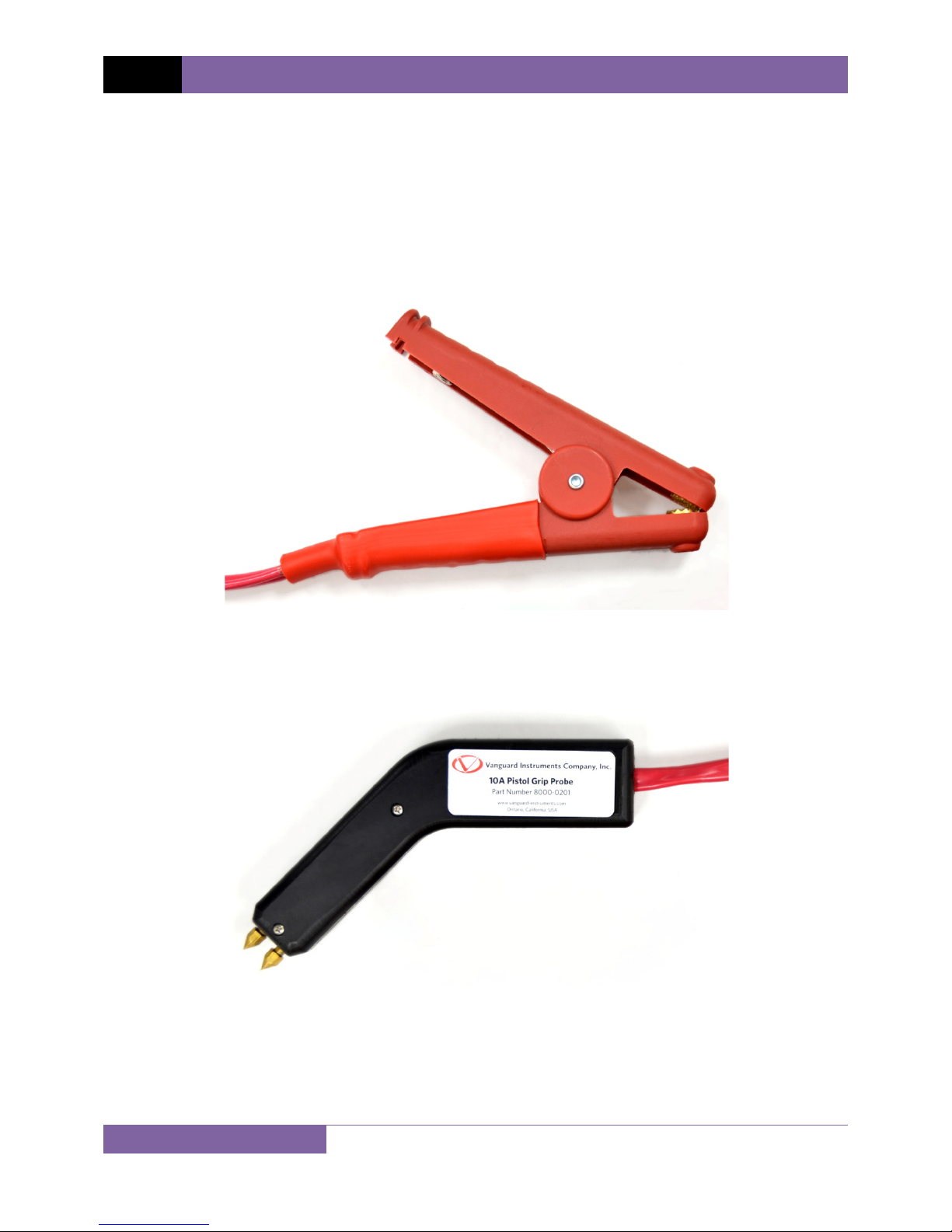
feature, only a single connection is needed to the device under test. Optional 10A rated pistol
grip probe (P/N 8000-0201), 10A rated hand probe (P/N 8000-0226), and 5A rated hand probe
(P/N 8000-0225) are also available.
Figure 1. Included Cable Set with Alligator Clamps (P/N 8000-0231)
Figure 2. Optional 10A Rated Pistol Grip Probe (P/N 8000-0233)
3
Auto-Ohm 10 USER’S MANUAL REV 1.0
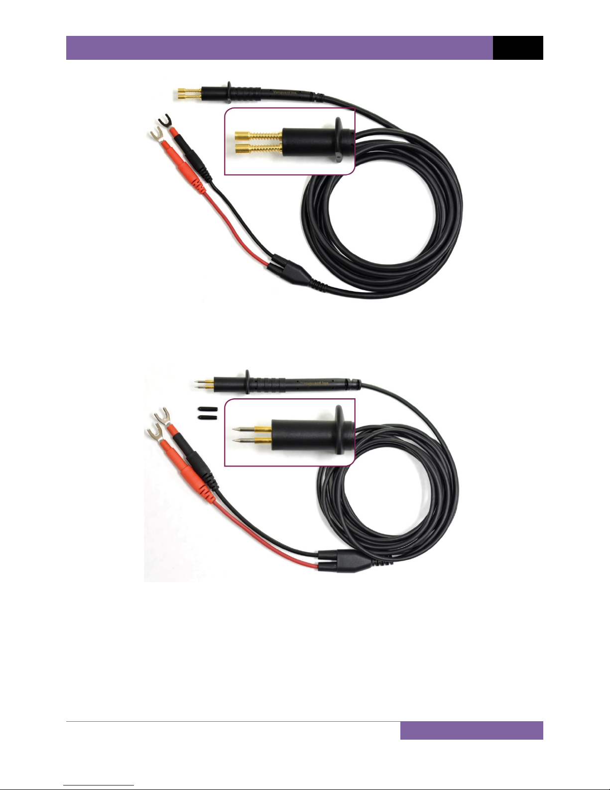
Figure 3. Optional 10A Rated Hand Probe (P/N 8000-0225)
Figure 4. Optional 5A Rated Hand Probe (P/N 8000-0226)
4

REV 1.0
T
CINP
R
D
U
M
I
m
S
a
p
o
n
b
,
D
1
1
1
d
e
C
6
)
)
P
2
m
m
pMa
9
9
9
0
9
9
9
9
9
9
0
9
9
0
9
9
0
9
9
0
n
s
n
e
h
5
a
0
y
c
p
F
g
n
p
r
r
m
n
o
n
=
8
t
n
c
2
2
µ
0
4
4
µ
0
µ
0
0
0
0
m
0
m
m
0
e
0
s
a
1.2
Auto-Oh
echnical
10 USER’S
pecificati
MANUAL
ns
SPE
REA
AND
TYPE
PHYSICAL
IFICATIONS
UT POWER
ESISTANCE
ING RANGE
ACCURACY
Table 1
Low Resista
14" W x 8" H
Weight: 7.8 l
100-240 Vac
Test
Current
10A
5A
1A
100mA
10mA
1mA
. Auto-Ohm
ce Micro-Oh
x 12" D (36 c
s (3.54 Kg)
50/60Hz
isplay
Min
000.0 99
1.0000 9.9
10.000 99.
100.00 25
000.0 99
1.0000 9.9
10.000 99.
100.00 99
00.000 99.
100.00 99
,000.0 5,0
000.0 99
,000.0 9,9
10,000 50,
000.0 9.9
10.000 99.
100.00 50
00.000 99.
100.00 99
,000.0 5,0
Dis
10 Technic
meter
x 19.4 m x 3
lay x Displa
Unit
.9 µΩ
99 mΩ
99 mΩ
.00 mΩ
.9 µΩ
99 mΩ
99 mΩ
.99 mΩ
99 mΩ
.99 mΩ
0.0 mΩ
.9 mΩ
9.9 mΩ
00 mΩ
99 Ω
99 Ω
.00 Ω
99 Ω
.99 Ω
0.0 Ω
l Specificati
.4 cm);
Resolutio
0.1µΩ
0.1µΩ
1µΩ
10µΩ
0.1µΩ
0.1µΩ
1µΩ
10µΩ
1µΩ
10µΩ
100µΩ
10µΩ
100µΩ
1mΩ
100µΩ
1mΩ
10mΩ
1mΩ
10mΩ
100mΩ
ns
Accura
±0.2%±0.
±0.2%±0.
±0.2%±2
±0.2%±2
±0.2%±0.
±0.2%±0.
±0.2%±4
±0.2%±4
±0.2%±2
±0.2%±2
±0.2%±20
±0.2%±2
±0.2%±20
±0.2%±2
±0.2%±20
±0.2%±2
±0.2%±20
±0.2%±2
±0.2%±20
±0.2%±20
y
µΩ
µΩ
Ω
µΩ
µΩ
µΩ
Ω
µΩ
Ω
µΩ
µΩ
µΩ
µΩ
Ω
µΩ
Ω
mΩ
Ω
mΩ
mΩ
5
BATTERIES
A
TO POWER
EN
VIRONMENT
HU
IDITY (MAX)
ALT
TUDE (MAX)
WARRANTY
NO
TE
DOWN
DISPLAY
CABLES
OPTIONS
The
tem
NOTE: State
Rechargeabl
Charge time:
Programmab
Backlit LCD (
Operating: -1
Storage: -30˚
Charging:0˚
90% RH @ 4
2,000m (6,5
15 ft (4.57 m
30 ft (9.14 m
probe (10A,
One year on
bove specif
erature of
accuracy for
Li-Ion, 3.7Vd
4 hours
le: 1 min, 2 mi
128 x 64 pixel
0˚C to 50˚C (+
C to 70˚C (-22
to 45˚C (+32˚
0˚ C (104˚ F)
2 ft) to full saf
cable set wit
cable set, 10
/N 8000-022
parts and labo
ications are
5°C (77°F).
bi-directional
c, 3400 mAh,
, 5 min, 10 mi
), viewable in
15˚F to +122˚
˚F to +158˚F)
F to +113˚F)
on-condensin
ty specificatio
alligator clam
ft (3m) hand p
), pistol grip p
r
valid at no
Specificatio
urrent mode
rotected (Qty
n
direct sunlight
)
s
s, power cabl
obe (5A, P/N
obe (10A, P/N
inal opera
s may cha
4)
and low light l
e, cable bag
000-0226), 1
8000-0201),
ing voltage
ge without
vels
ft (3m) hand
hipping case
nd at a
prior notice.
Auto-Ohm 10 USER’S MANUAL REV 1.0
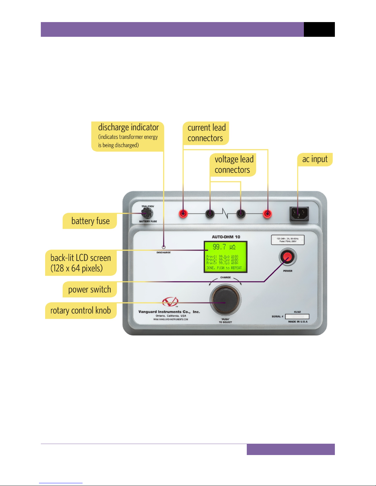
1.3 Auto-Ohm 10 Controls and Indicators
The Auto-Ohm 10’s controls and indicators are shown in Figure 5. The purpose of the controls
and indicators may seem obvious, but users should familiarize themselves with them before
using the Auto-Ohm 10. Accidental misuse of the controls will usually cause no serious harm.
Users should also familiarize themselves with the safety summary information found on the
front page of this User’s Manual.
Figure 5. Auto-Ohm 10 Controls and Indicators
6
 Loading...