

Page 1

INSTALLATION & OPERATION MANUAL
DO NOT DISCARD THIS MANUAL!
POWERMAX
GAS INFRA-RED WATER BOOSTER HEATERS
Model PM200 and PM400
IMPORTANT FOR YOUR SAFETY
WARNING: IF THESE INSTRUCTIONS ARE NOT FOLLOWED EXACTLY, FIRE OR
EXPLOSION MAY RESULT, CAUSING PROPERTY DAMAGE, PERSONAL INJURY
OR DEATH.
-Do not store or use gasoline or any other flammable liquids or vapors in the vicinity of
this or any other appliance.
-WHAT TO DO IF YOU SMELL GAS
• Do not try to light any appliance
• Do not touch any electrical switch
• Do not use any phone in the area
• Immediately call your gas supplier from another location.
• Follow gas suppliers instructions
• If you cannot reach the gas supplier, call the local fire dept. or 911
-If overheating should occur or the automatic gas valve fails to operate properly, turn off
the manual gas valve on the gas supply piping to the appliance.
-Installation and service of this equipment must be performed by a qualified installer,
service agency or the gas supplier.
tm
Tested to: ANSI Z21.10.3 1998
NSF Std. 5, 1992
800-624-4809 CAN/CGA 1-4.3 M98
Page 2

TABLE OF CONTENTS
Page
General Information 1
Installation Codes 2
Unpacking 2
Locating 2
Combustion Air/Ventilation 3
Exhaust Venting 3
Gas Piping 5
Water Requirements 6
Water Piping 7
Electrical 9
Wiring Diagrams 10
Operating Sequence 12
Start-up Procedure 13
Operating Instructions 14
To Turn Off Gas Appliance 15
Maintenance 16
Troubleshooting 17
Replacement Parts List 18
Limited Warranty 19
Appendix A 20
Sample Start Up Checklist 24
Interior View/Parts Breakdown 26
ii
Page 3

GENERAL INFORMATION
tm
The POWERMAX
gas fired, infra-red water booster heater provides 180 degree
sanitizing rinse water for commercial dishwashing machines. Dishware and utensils used
in the preparation and serving of food are required by Health Codes and the National
Sanitation Foundation (NSF) to be sanitized by hot (min. 180 degrees Fahrenheit) water or
a chemical sanitizing solution to destroy bacteria and parasitical organisms. The
POWERMAXtm booster heater operates as a semi-instantaneous water heater. As 180
degree rinse water is drawn from the unit, incoming supply water flow activates the burner
and pump to circulate the water through a high efficiency finned copper coil heat
exchanger. Heat is provided by an advanced infra-red ceramic fabric power burner which
heats and maintains a constant supply of 180 degree rinse water. When the dishwasher is
not in use, the POWERMAXtm continues operating for a few minutes before going into a
stand-by mode, operating only as needed to maintain a small (approx. 4.5 gallon) reservoir
of 180 degree water for the next dishwashing rinse demand.
1
Page 4

INSTALLATION CODES
Installation must be performed in accordance with state and local codes, or, in the
absence of local codes, with the following: National Fuel Code, ANSI Z223.1 (latest
edition) the National Electric Code (NEC) ANSI/NFPA 70 (latest edition). Canada:
CAN/CGA B149.1, CAN/CGA B149.2 and CSA C22.2 No. 1 (latest edition).
UNPACKING
Immediately after unpacking, check thoroughly for any possible shipping damage. If the
POWERMAXtm is found to be damaged, contact the carrier immediately (15 days
maximum). Be sure to save all the packaging materials for shipper’s inspection.
LOCATING THE POWERMAXtm BOOSTER HEATER
Locate the POWERMAXtm so that all required clearances are maintained. The appliance
must be located in an area that is clear and free from combustible materials, including
gasoline and other flammable or corrosive liquids and vapors. The booster heater should
not be located in an area where water leakage could cause damage to adjacent areas or
areas below the unit. If this is not possible, the booster heater should be installed in an
adequate catch pan (preferably stainless steel) that is properly drained. If appliance is
installed on carpeting, it must be installed on a wood or metal panel extending beyond the
full width and depth of the appliance by at least 3 inches (76.2mm) in each direction. The
booster heater should be installed with no more than five feet of pipe between the 180degree outlet and the dishwasher rinse valve (as specified by NSF-5). If the piping
exceeds five feet, the optional circulation return kit must be installed to maintain proper
temperature at the dishwasher rinse valve. The POWERMAXtm may be installed up to 150
feet from the dishwasher when using the circulation kit. Call factory for details.
INSTALLATION CLEARANCES
Minimum clearances from combustible or non-combustible construction -
8” (fire 2”, service 8”) Left side, 2” Right side, 6” Back, 0” Top, 24” Front (minimum for
service). The four 6” adjustable legs allow the unit to be leveled on uneven floors by
screwing the feet up or down as needed.
2
Page 5
COMBUSTION AIR / VENTILATION
tm
The POWERMAX
must be provided with an adequate supply of air for proper
combustion and ventilation as required by the National Fuel Gas Code, ANSI Z 223.1 or
any local codes that supercede the National Code. Do not obstruct the combustion and/or
ventilation air supply openings.
CAUTION: Combustion air must not be contaminated by corrosive vapors or fumes, i.e.
salt, chlorine, refrigerant gases, detergents, paints, cleaners, etc.. Any damage caused by
insufficient or contaminated combustion air or improper venting will not be covered under
the warranty.
EXHAUST VENTING
The POWERMAX
tm
Booster Heater is classified as a category IV appliance (positive flue
pressure, flue gas temperature of approximately 190 degrees Fahrenheit, possible
condensate). Vent piping must be one of the types detailed in this manual or a factory
approved (in writing) alternate and must be installed according to the vent pipe
manufacturers instructions. All joints must be properly sealed and secured to maintain
joint integrity. All vent piping must slope toward the appliance a minimum of 1/4 inch per
foot of length. The National Fuel Gas Code, ANSI Z223.1 requires that the booster heater
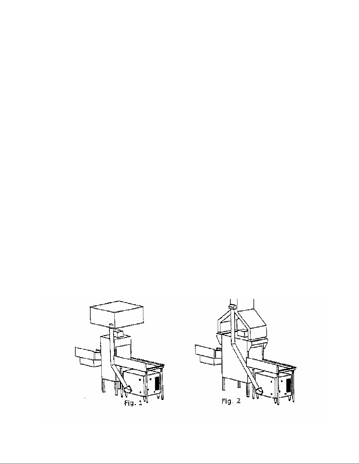
be vented in one of the following three ways:
1. Into the dishwasher exhaust system. (See fig.1). The vent pipe must not penetrate
any grease filter, but should terminate within the hood “capture zone”. In cases of a
“pantleg” type of vent (see fig. 2), the vent pipe may terminate below an approved
‘eyebrow’ penetration of the duct. When vented into the dishwasher exhaust system,
an electrical interlock must be provided (by others) to prevent the appliance from
firing if the exhaust system is not providing sufficient draft for any reason.
3
Page 6
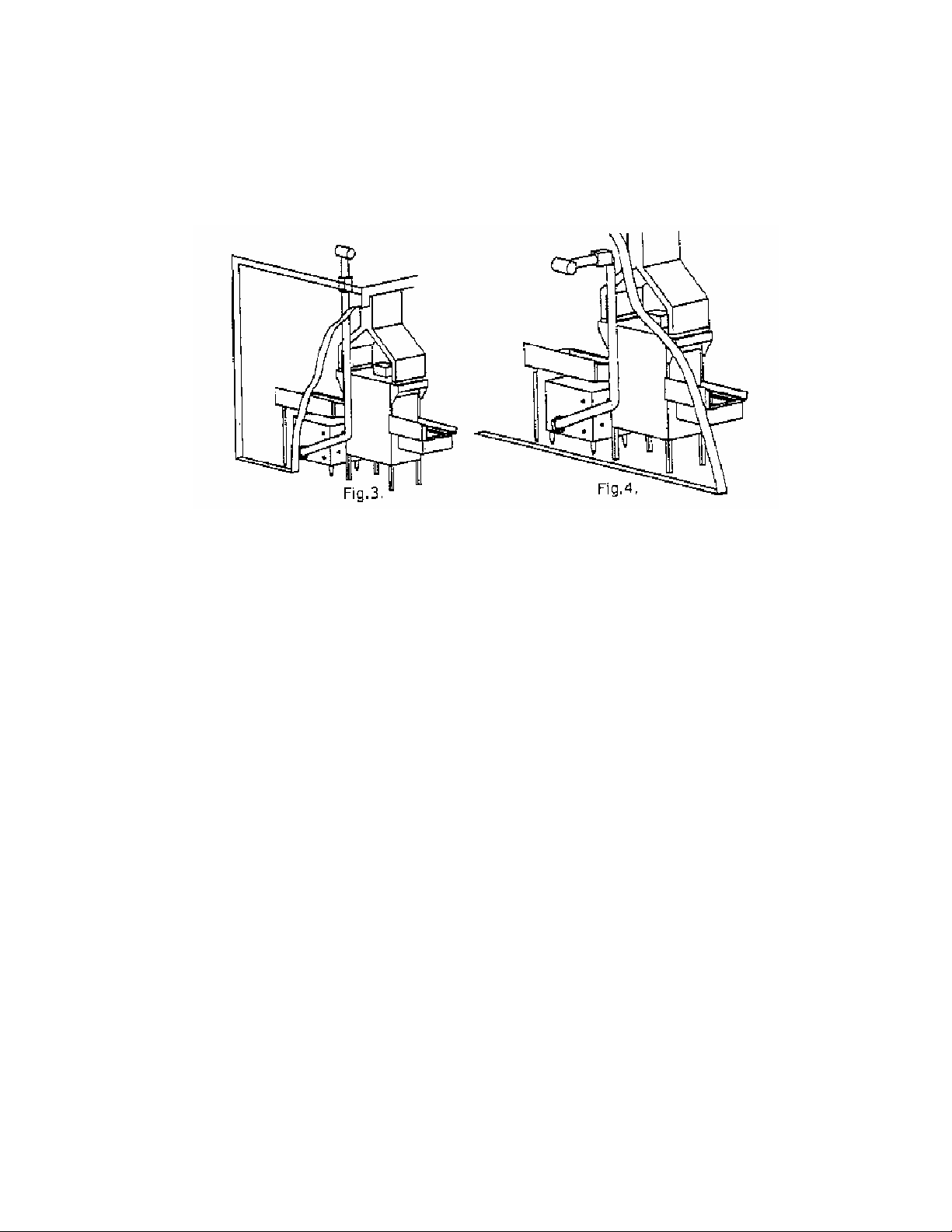
2. Through the ceiling/roof (see fig.3) or through a sidewall (see fig. 4). Type B-1 vent
pipe (inch min. diameter) may be used when venting vertically through the roof,
provided a one inch minimum clearance to combustible material is maintained
throughout and the vent terminates into a listed wind cap above the roof.
3. Vented freely into the room or space where it is installed, provided that:
a) A Mechanical exhaust system is present in the space where the
booster heater is installed.
b) An electrical interlock is provided (by others) so that the booster will not fire if the
exhaust system is not providing adequate ventilation to the area.
c) The total BTU input rating of all the unvented gas appliances installed divided by
the total cubic foot volume of the room area (including any adjacent areas that
cannot be physically closed off from the installation area) does not exceed 20
BTU’s per hour per cubic foot of space.
For sidewall venting, the booster heater should be located as close as possible to the wall
being used. The minimum and maximum wall thickness is determined by the wall thimble
available from the vent manufacturer. Refer to the vent manufacturer’s installation
instructions.
All horizontal runs of vent pipe must have a minimum rise of 1/4 inch per foot of length and
must be supported every 5 feet or less (3 feet in Canada) and at every elbow.
For horizontal venting: The total length of approved 4 inch diameter vent pipe can be a
maximum of 40 feet, including two 90 degree elbows and one termination vent. For each
elbow above two, reduce the total allowable vent length by ten feet. Minimum horizontal
vent length is 2 feet.
For vertical venting: The maximum length of approved 4 inch diameter vent pipe is the
same as above; the same requirements for elbows and termination vent apply; the
minimum length for vertical venting is 5 feet. An auxiliary power vent kit is available for
installations where the vent length must exceed these lengths. Call the factory for
assistance. Additional requirements when venting through a sidewall:
-The vent terminal shall be located at least three feet above any forced air inlet located
within ten feet; at least four feet below and four feet horizontally from, or one foot above
4
Page 7

any door, opening window or gravity air inlet into any building. It shall also have a
minimum horizontal clearance of four feet from any electric meter, gas meter, regulator,
relief valve or other equipment.
-The vent terminal shall be located not less than seven feet above grade when it is
adjacent to public walkways.
-The bottom of the vent terminal shall be located at least twelve inches above grade or
ground or the normally expected snow accumulation level.
The snow level may be higher on walls exposed to prevailing winds.
-Avoid areas where local experience indicates that condensate drippage may cause
problems, such as above planters, patios, public walkways or areas where condensate or
vapor could cause a nuisance or hazard, or where its discharge could be detrimental to the
operation of regulators, relief valves or other equipment.
Examples of ACCEPTABLE VENT PIPING/ See Appendix A
MANUFACTURER MODEL MATERIAL
SPECIFICATION
Heat-Fab Inc.
38 Haywood St.
Greenfield, MA 01301
Z-Flex US, Inc.
20 Commerce Park North
Bedford, NH 03110
Flex-L International, Inc.
6385 Kennedy Rd
Mississauga, ON
L5T2W4
Saf-T-Vent AL 29-4C
Stainless Steel
Z-Vent AL 29-4C
Stainless Steel
StaR-34 AL 29-4C
Stainless Steel
Termination Box
Termination Tee
Part Name
Tee
Rain Cap
Mitre I Straight
Tee
Rain Cap
Wall Thimble
3”
Part Number
7390TEE
5300C1
7390GC
#02SVSTTX-3
#02VRSRCX03
#02SVSRTX-3
SRTT03
SRWT153
4”
Part Number
7490TEE
5400C1
-
#02SVSTTX-4
#02VRSRCX04
#02SVSRTX-4
SRTT04
SRWT154
GAS PIPING
The gas inlet pipe size is 3/4 inch NPT, male thread, located at the lower right front corner
of the appliance. The gas supply piping must be sized to adequately provide the input
BTU/hr rate for the appliance at the specified flowing pressure (see table 1). The
maximum inlet gas pressure must not exceed the maximum value shown in table 1. The
minimum gas pressure shown in Table 1 is for purposes of input adjustment.
FLOWING Gas Pressure Requirement (not static)
Inches W.C. (Water Column)
Incoming Line Pressure Natural Gas/LP
Minimum Maximum
Manifold
Pressure
PM200 4.5”NG/10”LP 10.5”NG/14”LP 3.5”NG/7.5”LP
PM400 4.5”NG/10”LP 10.5”NG/14”LP 3.5”NG/7.5”LP
TABLE 1
5
Page 8
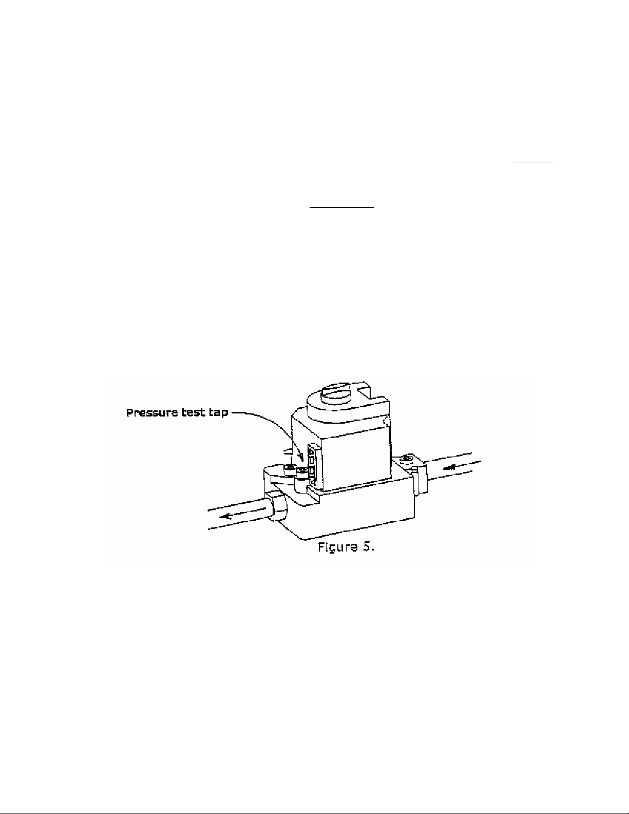
The gas valve is provided with a pressure tap to measure gas pressure downstream, which is also
the manifold pressure (fig. 5.). The gas piping must have a sediment trap ahead of the heater gas
controls and an approved manual shut-off valve (provided by others) located outside the jacket and
easily accessible. The heater and its gas connections must be leak tested before placing the
appliance in operation. DO NOT use an open flame for leak testing. The heater must be isolated
from the gas supply piping by closing its individual manual shut-off valve during any pressure
testing of the gas supply piping at test pressures equal to or less than 1/2 p.s.i.g. (3.5 kPa). The
heater and its individual shut-off valve must be disconnected from the gas supply during any
pressure testing of that system at test pressures in excess of 1/2 p.s.i.g. (3.5 kPa). Dissipate test
pressure from the gas supply line before re-connecting the heater and its manual shut-off valve to
the gas supply line.
CAUTION: Failure to follow this procedure may damage the gas valve and cause a
dangerous condition. Over pressured gas valve damage is not covered under
warranty.
NOTE: Do not use Teflontm tape on gas line threads. Use only a flexible thread sealant
approved for use with fuel gases.
WATER REQUIREMENTS
Local water conditions vary greatly between even near-by locations and can greatly affect
the performance and maintenance requirements of warewashing equipment, including
your booster heater. Proper water conditions will provide lower chemical costs, improved
cleaning performance, reduced spotting and longer equipment life as well as more efficient
labor use and reduced damage to dishware and utensils. Proper water treatment for
effective and efficient performance of this equipment will vary depending upon the makeup of the local water supply.
6
Page 9

Recommended water hardness is 4-6 grains of hardness per gallon. Chlorides must NOT
exceed 50 parts per million. Water hardness above 6 grains per gallon should be treated
with a proper water conditioner (water softener or in-line treatment). Water hardness
below 4 grains per gallon also requires water treatment to reduce its corrosive effects.
Sediment, silica, chlorides or other dissolved solids may require particulate filtration or
reverse osmosis treatment. Proper water treatment has been shown to reduce machine
cleaning, mineral build-up, detergent usage and corrosion of metal surfaces in booster
heaters and dishwashers.
Damage caused by water conditions is not covered under warranty.
WATER PIPING
WARNING: All piping and plumbing connections must comply with applicable
sanitary, safety and plumbing codes.
CAUTION: All piping and any components connected to this appliance for the
purpose of space heating shall be suitable for use with potable water. Toxic
chemicals, such as used for boiler treatment, shall not be introduced into the
potable water used for space heating. This appliance, when used to supply
potable water, shall not be connected to any heating system or component(s)
previously used with a non-potable water heating appliance or system.
The inlet and outlet water connections are 1 inch NPT (inlet is 1” female pipe, outlet is 1”
male pipe). An inlet and outlet union adaptor is provided with your POWERMAXtm Booster
Heater.
The inlet water supplied to the booster heater should be a minimum of 110-degrees
Fahrenheit, except in the case of single rack, door type dishwashers and some “watersaver” conveyor machines, in which case incoming water can be as low as 45 degrees
tm
Fahrenheit. DO NOT connect the POWERMAX
Booster Heater to a cold water supply
pipe if it is to be used with a full flow conveyor dishwasher.
Recommended flowing water pressure to the booster heater is 45 p.s.i. Flowing water
pressure at the dishwasher rinse valve should be 20 p.s.i. An optional pressure regulating
valve and pressure gauge for the booster heater outlet is available from Vanguard
Technology if the dishwasher is not equipped with these items. The supply water inlet to
the booster heater does not require a pressure-regulating valve unless the supply water
pressure exceeds 50 p.s.i. A full-flow shut off valve must be provided in the water supply
piping to the booster heater. Installation of a suitable water hammer arrester is
recommended between the booster heater and the dishwasher rinse valve.
A drain valve assembly is provided for installation on the lower outlet at the back of the
booster heater.
The Temperature and Pressure Relief valve is installed at the left side of the booster
heater. Install a suitable 3/4” i.d. drainpipe from the discharge of the Temperature and
Pressure Relief valve to a suitable drain or catch pan with drain. The Temperature and
Pressure Relief valve should be manually test-operated at least once annually to ensure
that it is functioning properly. Be careful when operating the relief valve.
7
Page 10

Follow instructions on the tag located on the Temperature and Pressure Relief valve to
avoid contact with hot water discharge and to prevent water damage from operation of the
valve.
Repair or alteration of the Temperature and Pressure Relief valve in any way is prohibited
by National Safety Standards and local codes. DO NOT PLUG THE RELIEF VALVE OR
INSTALL A SHUT OFF VALVE OR ANY OTHER RESTRICTION IN THE DISCHARGE
DRAIN LINE! The booster heater should be located as close to the dishwasher rinse valve
as possible. If the booster heater is installed more than 5 feet from the dishwasher rinse
valve, an optional rinse water re-circulation kit is available from Vanguard Technology and
must be used to insure a consistent water temperature of 180-degrees at the rinse valve
(Fig.6.).
NOTE: All water supply piping to the booster heater must be completely flushed of
all debris and flux residue before connection to the booster heater. Damage caused
by debris or aggressive flux residue will not be covered under warranty
If booster heater is installed in a closed water supply system, such as one having a
backflow preventer in the water supply line, means shall be provided to control thermal
expansion. Contact the water supplier or local plumbing inspector on how to control this
situation or call the factory.
8
Page 11

ELECTRICAL
The electrical power supply requirement for the booster heater is 120 volts, AC, 60Hz, 6.0
amps or less. Field wiring connections and electrical grounding must comply with local
codes, or, in the absence of local codes, with the latest edition of the National Electric
Code (NEC), ANSI/NFPA 70. NOTE: Polarity must be observed for the booster heater to
operate properly. Consult wiring diagram. Provide a separate fused circuit from the main
electrical panel to the booster heater and a means of disconnecting within sight of the
heater. Electrical connection is made from the bottom left front of the unit and into the
2”X4” field wiring connection box. All internal electrical components are factory wired and
operate with the heater control system. NOTE: If it is necessary to replace any of the
original wiring, it must be replaced with 105 degree centigrade rated wire or its equivalent.
CAUTION: DO NOT TURN THE POWER SWITCH ON UNTIL THE BOOSTER
HEATER HAS BEEN FILLED WITH WATER AND ALL AIR HAS BEEN PURGED
FROM HEAT EXCHANGER AND THE ACCUMULATOR TANK.
If an auxiliary power vent is installed, or in certain cases, if the booster heater is vented
through the dishwasher exhaust system, an airflow-proving switch must be installed in the
duct system to interrupt power to the booster heater and prevent its operation without
sufficient draft. The airflow-proving switch is provided by others.
If the optional circulation kit (for remote booster installation) is used, it is wired separately
from the booster heater through the provided lighted switch box.
CAUTION: Label all wires prior to disconnection when servicing controls. Wiring errors
can cause improper and dangerous operation. Verify proper operation after servicing.
9
Page 12

10
Page 13

11
Page 14

The booster heater is designed to produce 180-190 degree sanitizing rinse water for
commercial dishwashing machines. Specific performance depends upon the exact water
flow and supply water temperature. (See table)
Temperature rise Gallons per Minute Gallons per Hour
40o F 8.7 520
50o F 7.0 420
60o F 5.8 348
70o F 5.0 300
140o F 2.5 (7.5 for 15 sec. Per minute) 150
After the necessary power, water, gas and vent connections are completed correctly and
all air is purged from gas and water piping, the unit is started by turning on the power
switch located on the top, front of the left side panel. The combustion air fan will start and
run continuously and the digital temperature display will light, showing the water
temperature in the accumulator tank. If the tank temperature sensor detects water
temperature below the set point, it will turn on the internal circulating pump, prove water
flow, combustion air flow and hi-limit compliance and activate the hot surface igniter.
Following a 3 second warm up for the igniter, the gas valve opens and the burner ignites.
If the burner flame is not proved within a few seconds, the gas valve automatically closes.
This cycle will repeat 3 times. If ignition/flame is not proved the control will go into
automatic lock-out, requiring a re-set. Re-set is accomplished by turning power switch to
‘off’ for 10 seconds and then turning back on. When the tank water temperature exceeds
the thermostat set point, the burner will shut off until the next call for heat.
The internal circulating pump will operate whenever the thermostat is calling for heat. The
combustion air blower operates continuously whenever the ‘on-off’ switch is on.
The operating temperature control is factory-set and is not to be user-adjusted. If
temperature rise is not satisfactory, call your service agency and/or call the factory.
OPERATING SEQUENCE
PowerMax200tm Performance Data
12
Page 15

POWERMAX
For your safety, read completely before operating.
CAUTION: DO NOT turn Power Switch ‘on’ until the booster has been filled with
water and all air has been purged from the water lines and accumulator
tank.
FILL THE BOOSTER HEATER
Open the water supply valve at the Booster Heater water supply inlet and fill Booster
Heater. Manually open the temperature/pressure relief valve on the left side of the
cabinet to vent air from water piping. Cycle dishwasher to ensure that all air is
purged from the system and to flush out any contaminants left from piping process.
CHECK ELECTRIC CONTROLS
Do this procedure with the manual gas valve CLOSED (gas supply off). With water supply
valve open (water side under pressure) and with manual gas supply valve in CLOSED
position (no gas flow to unit), push power supply rocker switch on left, top side of cabinet
to ON position. Combustion air fan should start, digital temperature readout should
illuminate and indicate water temperature in accumulator tank and LED indicators in
readout panel should illuminate. If water temperature is below control set point, circulating
pump will start, air flow, water flow and hi-limit E.C.O.’s will prove and ignition system will
be powered. Red LED on ignition control will illuminate briefly, confirming internal selfcheck. Following 2-3 seconds igniter warm-up (observe igniter through viewing window to
verify), an audible ‘click’ will be heard from the gas valve opening. With gas supply off,
ignition will not occur and flame-proving sensor will shut off gas valve. This process will
repeat for, 3 cycles, after which the ignition system will automatically lock-out, requiring a
manual re-set. The combustion fan will remain on low speed, providing a continuous
purge of the combustion chamber. Manual re-set is accomplished by turning off power
switch on booster left side panel for 10 seconds, then turning back on.
tm
START-UP PROCEDURE
13
Page 16

FOR YOUR SAFETY, READ BEFORE OPERATING
WARNING! - IF YOU DON’T FOLLOW THESE INSTRUCTIONS EXACTLY,
A FIRE OR EXPLOSION MAY RESULT CAUSING PROPERTY DAMAGE,
PERSONAL INJURY OR DEATH.
A. This appliance DOES NOT have a standing pilot ignition system. It is equipped with a
hot surface ignition device that automatically lights the burner. DO NOT attempt to
light the burner by hand.
B. Before starting the appliance, smell all around the appliance area for gas odor. Be
sure to smell next to the floor because some gases are heavier than air and will
collect on the floor.
WHAT TO DO IF YOU SMELL GAS
• DO NOT try to light any appliance.
• DO NOT touch any electric switch.
• DO NOT use any phone in your building.
• IMMEDIATELY call your gas supplier from a neighbor’s phone.
Follow the gas supplier’s instructions. If you cannot reach your gas supplier, call
the fire department and/or ‘911’.
C. Use only your hand to push in and turn the gas control knob. NEVER use tools. If the
knob will not turn by hand, do not try to repair it. Call a qualified service
technician. Using force or attempting to repair may result in a fire or explosion.
D. Do not operate this heater if any part has been under water. Immediately call a
qualified service technician to inspect the heater and replace any part of the control
system and any gas control that has been under water.
OPERATING INSTRUCTIONS
1. STOP! Read the safety information above on this label.
2. Turn off electrical power to appliance at switch on upper left side panel.
3. Remove front access panel by lifting on handle until bottom of panel is released, tilt
bottom of panel away from unit and remove.
4. This appliance is equipped with an ignition device which automatically lights the
burner(s). DO NOT try to light the burner(s) by hand.
5. Turn the gas control knob clockwise to the ‘OFF’ position. (Fig. 7)
6. Wait 5 minutes to clear out any gas. If you smell gas, stop and follow the
instructions under “WHAT TO DO IF YOU SMELL GAS” (ABOVE). If you do not
smell gas, proceed to the next step.
7. Turn gas control knob counterclockwise to the ‘ON’ position.
8. Turn on electrical power to the appliance. Be careful not to contact any live
electrical connections when access panel is open.
9. If appliance does not ignite, there may be air in the gas supply system. Repeat the
cycle several times to remove air.
10. If the appliance will not operate, follow the instructions under “TURN OFF GAS TO
APPLIANCE” (following) and call your service technician or gas supplier.
11. Replace front access panel.
14
Page 17

TO TURN OFF GAS TO APPLIANCE
1. Turn off all electric power to the booster heater if service is to be performed.
2. Turn off manual gas valve in gas supply piping.
3. Remove front access panel by lifting panel to release bottom, tilting panel away from
unit and removing panel.
4. Push in and turn gas control knob clockwise to the ‘OFF’ position.
5. Replace front access panel.
WARNING!
IF OVERHEATING OCCURS OR THE GAS SUPPLY FAILS TO SHUT OFF
CORRECTLY, DO NOT TURN OFF OR DISCONNECT ELECTRIC SUPPLY TO THE
PUMP. SHUT OFF GAS SUPPLY AT THE MANUAL GAS VALVE IN GAS SUPPLY
PIPING. IF WATER IS LEAKING FROM UNIT, AFTER TURNING OFF GAS, LET
BURNER COOL, THEN TURN OFF POWER AND SHUT OFF WATER SUPPLY VALVE.
15
Page 18

MAINTENANCE
Lubrication
The water pump motor and the combustion air blower are permanently lubricated and
require no periodic maintenance. Auxiliary power vent motor (depending upon model)
may or may not need periodic adjustment or lubrication. Consult power vent manual.
Vent System
Check the vent system annually for damage and/or obstruction. Any deformation of the
vent system should be examined carefully to determine the cause of the deformation. The
problem MUST be rectified and any damage to the vent system MUST be repaired.
Check Burner Flame Condition
When the burner is operating properly, the flame will appear to have a light orange base
with a blue tint as you look through the burner observation window and across the burner
surface (fig.8 ). Inspect the burner periodically through the observation window. If areas
of the burner appear different or if the observation window is obscured, contact your
authorized service agency to have the burner inspected for proper operation. If the burner
is burning bright orange, red or white; it is too hot and will burn up igniters at an excessive
rate. Call factory and/or authorized service company to adjust air shutter.
Piping and General Condition
Periodically inspect the booster heater for any signs of water leakage, combustion byproduct leakage (soot, etc.), or wiring damage (electrical arcing, insulation damage).
Contact your authorized service agency to correct any damage or improper operation that
is discovered.
Check Air Filter
Regularly remove and inspect externally mounted air filter on the left side of booster. Filter
is easily cleaned with soap and water. A clogged filter will restrict flow of combustion air
which can lead to malfunction and internal damage. Damage caused by a blocked or
clogged filter is not covered under the warranty.
16
Page 19

CAUTION: Label all wires prior to disconnection when servicing
controls. Wiring errors can cause improper and dangerous operation.
Verify proper operation after servicing.
PROBLEM
3. On-Off switch
powered, Unit does
not operate.
TROUBLE SHOOTING
CAUSE
a. No power to heater.
b. Manual reset Hi-limit
tripped.
c. Vent fan interlock not
proving (if auxiliary
power vent or E-Z
Vent system) is
being used.
REMEDY
a. Check circuit breaker
b. Manually reset hi-
limit. Determine
cause. If hi-limit trips
again, call service.
c. Turn on fan, check
switch.
2. Unit energized,
blower not operating,
pump not operating,
burner(s) not on.
3. Unit energized,
blower and pump
operating, burner(s)
are NOT on, ignition
control LED flashing.
4. Unit energized,
blower on, pump not
operating, burner(s)
NOT on.
Note: For service and/or parts call your authorized service agency or the
factory @ 1-800-624-4809
17
a. Fan defective.
b. Fan relay defective
or wiring
disconnected.
a. Igniter Defective
b. Water flow switch
not proving.
c. Air flow/flue
blockage switch not
proving.
d. Control relay(s)
defective.
e. Control sensor(s)
defective.
f. Control board
defective
g. Ignition control
defective.
h. Burner flame not
proving
a. Pump defective
b. Relay defective
a. Check, replace fan.
b. Check, correct.
c. Check, clean air filter
a. Replace igniter or
call Service
b. Check, replace flow
switch.
c. Clear flue. Repair or
replace switch,
d. Call Service
e. Call Service
f. Call Service
g. Call Service
h. Check, replace flame
sensor
a. Call Service
b. Call Service
Page 20

REPLACEMENT PARTS LIST
When ordering parts, always refer to the Model number and Serial Number.
The data plate is mounted on the electrical panel face behind the front cover
panel. NOTE- Part numbers may change without notification. To obtain the
most recent part numbers contact the Factory or your authorized Vanguard
service agency.
Model PM200, 199,900 BTU/Hr. & Model PM400, 399,800 BTU/Hr.
PART# DESCRIPTION PART#
19052-01612 Blower 20000-00303 Orifice, LP, PM
10050-00039 Board, Temp. Control 20000-00302 Orifice, NG, PM
10592-20000 Control Panel, Complete 20000-00031 Orifice, Pilot, PM LP
10050-00043 Display, Digital Temp. 20000-00030 Orifice, Pilot, PM NG
32200-34209 ECO, Hi-Limit, PM 20021-20001 Pilot Hood Assm w/Ign.Plate, gasket
10051-02383 ECO, Hi-Limit, Manual Reset 75220-90011 Pump, Grundfos W/O Housing 26-99F
19052-20075 Filter, Air FF-5 75220-26099/ Pump, Grundfos, 26-99BF complete
19020-70200 Flex Tube, Gas, 1" x 18" 10080-00025 Relay, Power
19020-70201 Flex Tube, Gas, 7/8x 12" 10050-00042 Sensor, Flame, 18" Lead Wire.
19020-70202 Flex Tube, Gas,1/4ODX18" 10550-00141 Sensor, Temp PM 41"
10080-02466 Gas Control Valve, Honeywell 19010-70001.159 Solonoid, Hi-Lo Gas, LP
10080-02602 Gasket, Igniter Plate 19010-70001.250 Solonoid, Hi-Lo Gas, NG
75220-90051 Gasket, Pump Flange 10080-19101 Switch, Air
10080-02465 Ignition Control, Fenwal 10070-00110 Switch, Water Flow, 1".
40000-40004 Legs, Black 10080-00071 Switch, Sq. Rocker.
50304-20001 Manifold, Cold-Lower, 200 10570-00103 Transformer, 120V/ 24V
50303-20001 Manifold, Cold-Upper, 200 10070-00104 Transformer, 120V/12v, 596
50603-20001 Manifold, Hot, 200 19025-70015 Tube, Vent Pipe Drain
10080-02601 Mini-Igniter, 120V, 250 C 19025-70012 Tube, Air Switch
20000-00304 Orifice, Hi-altitude NG/LP, PM 13053-07501 Valve, T & P. 3/4"
DESCRIPTION
18
Page 21

LIMITED WARRANTY:
Products manufactured by Vanguard Technology. Inc.
are warranted to be free from defects in material and
workmanship, when installed and maintained in
accordance with Vanguard’s instructions and in normal
use and service for the time periods, terms and
conditions as set forth below:
1) For a period of One Year
installation, but no longer than 18 months from
factory shipment, Vanguard will, at its sole
discretion, repair or replace defective parts,
assemblies or entire units, including labor costs
of its authorized service agency. Travel expense
of Vanguard’s authorized service agent will be
paid for the first ninety (90) days of this period,
not to exceed sixty (60) miles or two (2) hours.
2) For an addition al Four Years
warrants the fin tube heat exchanger in the
PowerMax Gas Booster to be free from defects
in material or workmanship. At Vanguard
Technology’s sole discretion and in accordance
with this warranty, defective heat exchangers will
be replaced on a pro-rated and parts only basis.
i.e. Owner will pay a percentage of the current
list price of a replacement heat exchanger as
follows: Failure within first year, no charge: within
second year, 20%; within third year, within fourth
year, 60%; within fifth year 80%.
3) The stainless steel accumulator is covered by a
limited lifetime warranty and is warranted to be
free from leaks for this time. Any attached
gauges; controls or other parts are subject to the
standard one-year parts and labor warranty.
This warranty is limited to the foregoing and does not
apply to defect or malfunction resulting from or caused
by installation, operation or maintenance not in
accordance with manufacturer’s instructions, damage
related to shipping, accident, abuse, fire, flood, or other
acts of God; units operated in corrosive or other
damaging atmospheres or at temperatures outside
specified operating range. Damage caused by
freezing, improper water conditions (excessively
from date of
, Vanguard
acidic or alkaline water, excessive pressure, chemical
contamination, sediment build-up, etc.), incorrect
electrical supply or connection, insufficient combustion
air or negative draft, insufficient water supply, stray
current or voltage conducted through water piping, or
unauthorized alteration shall in no way be covered
under this warranty. Cleaning of filters, pumps, valves,
burners, fans or electrical connections, tightening of
threaded connections and/or adjustment or calibration
of controls is considered a part of normal installation
and/or maintenance and is not covered under this
warranty. Hot surface igniters are considered a
consumable item, similar to a spark plug, and are not
generally considered a warranty item. Accessory
components sold but not installed by Vanguard are
covered by a one-year parts-only warranty. Warranty
on replaced parts or assemblies shall be the lesser of
90 days or the unexpired portion of the original
warranty. Factory reconditioned and tested parts may
be used to satisfy claims under this warranty. Warranty
work shall be done only by Vanguard Technology’s
authorized service agency during normal working
hours. Overtime labor will not be paid under this
warranty.
There are no other expressed or implied warranties of
any kind, including but not limited to any implied
warranty of merchantability or fitness for any particular
purpose or usage. The remedies under this warranty
as set forth here-in are at the exclusion of all others and
Vanguard Technology, Inc., neither assumes nor
authorizes anyone to assume for it any other
obligations. In no event shall Vanguard Technology,
Inc. be liable for any remote or consequential damage
of any nature, no matter how arising or from any cause
whatsoever, or any amounts in excess of the selling
price of the product. Vanguard Technology’s policy of
constant Quality Improvement means that prices,
specifications, and policies are subject to change at any
time and without notice.
VANGUARD TECHNOLOGY, INC.
29495 Airport Road, Eugene, OR 97402
541-461-6020 • FAX 541-461-6023
800-624-4809
R12/03
19
Page 22

TYPICAL SPECIAL STAINLESS STEEL VENTING
For use with Category II, III, IV appliances
Contact Local Building or Fire Officials About Restrictions and Installation Inspections in your area as well as National codes:
USA -National fuel gas code ANS1-Z223.l
CANADA -CAN\CGA-B 149.1 or .2 Fuel Burning Installation Code
Please refer to appliance manufacturers’ instructions to determine proper sizing and connection of venting system to appliance, including
maximum horizontal length, maximum height, and installation clearances (air spaces). The proper operation of the vent system and
appliance requires parts specified by Z-FLEX with no deletions or substitutions. NOTE: Co-venting with other appliances is
PARTS LIST
COMPONENT
10 FOOT PIPE SVEPWC0310 SVEPWC04I0
8 FOOT PIPE SVEPWC0308 SVEPWC0408
5 FOOT PIPE SVEPWC0305 SVEPWC0405
4 FOOT PIPE SVEPWC0304 SVEPWC0404
3 FOOT PIPE SVEPWC0303 SVEPWC0403 FIRESTOP SUPPORT SVSFSS03 SVSFSS04
2 FOOT PIPE SVEPWC0302 SVEPWC0402 FTRESTOP SPACER SVSFSX03 SVSFSX04
1 FOOT PIPE SVEPWC0301 SVEPWC0401
6 INCH PIPE SVEPWC03.5 SVEPWCO4.5
90 0ELBOW SVEEWC0390 SVEEWC0490
45 ELBOW SVEEWC0345 SVEEWC0345 TOP SUPPORT SVSLSX03 SVSLSX04
HORJZ. DRAIN TEE SVEDWC03 SVEDWC04 STORM COLLAR SVSSCX03 SVSSCX04
VERTICAL DRAIN TEE SVEVWC03 SVEVWC04
WALL THIMBLE
WM GV STARTER SVEWMG03
DRAIN TUBE KIT
Z-FLEX recommends that the installation be performed by an experienced professional who works with venting systems on a-regular
basis. These instructions are intended as a guide to assist a professional installer.
When the Z-VENT system is installed, the following should be observed:
1. A venting system that exits the structure through a sidewall or the like, shall terminate not less than 12 inches (254 mm) above the ground
(see illustration # 2, page 4).
2. The termination of a system shall be located above the snow line in geographical areas where snow accumulates. The termination area
should be kept clear of snow and ice at all times.
3. The vent shall not terminate less than 7 ft. (2.13 m) above a paved sidewalk or driveway.
4. The termination shall be 6 ft. (1.8 m) or more from the combustion air intake of any appliance.
5. The system shall terminate more than 3 ft. (.91 m ) from any other building opening, gas utility meter, service regulator or the like.
6. Exterior mounted venting systems should be enclosed below the roof line with a chase to limit condensation and protect against
mechanical failure.
NOTES:
A. The Z-FLEX SPECIAL STAINLESS VENT SYSTEM is for use only with appliances having a positive vent pressure of 3” of water column
or less.
B. Except for installation in one and two family dwellings, a venting system that extends through any zone above that on which the connected
appliance is located shall be provided with an enclosure having a fire resistance rating equal to or greater than that of the floor or roof
assemblies through which it passes
C. Do not place any type of insulation in any required air spaces surrounding the venting system.
D. A termination must be used on all installations to assure proper operation and to prevent debris from entering the venting system.
3” SYSTEM CAT. # 4” SYSTEM CAT. # COMPONENT 3” SYSTEM CAT. # 4” SYSTEM CA1~#
SVSWTX03 SVSWTX04 WM TERM COUPLING SVSTPX03
SVEDTK WM CGI STARTER SVEWMFA03
ADJUST. FLASHING
REDUCER 4” TO 3”
FLAT FLASHING
LOCKING BAND
TERMINATION TEE
TERMINATION BOX
RAIN CAP
Z-VENT SEALANT
AMETEK FAN CONN.
SVSADJ03 SYSADJ04
SVSERWC0403 SVSR0404
SVSSCS03 SVSSCS04
SVSLBX03 SVSLBX04
SVSTTX03 SVSTTX04
SVSRTX03 SVSRTX04
SVSRCX03 SVSRCX04
GE106X
SVSACA03
APPENDIX A
prohibited
20
Page 23

Appendix A
JOINT PROCEDURE
(see illustration #1 below)
1. The outside of male end and inside of female end of pipe must be cleaned before applying silicone
bead. Remove dirt, grease, and moisture from surface to be sealed. Dry surface or allow to dry
thoroughly.
2. Apply high temperature silicone approxi mately one half inch from end around male end of pipe and
along both sides of seam for one inch in an even 1/4” bead as per illustration #1.
3. Pipes can now be pushed together as far as they will go. The seams on pipes should be aligned and
oriented upwards in all horizontal applications. Apply another bead of silicone around this joint and
smooth out.
4. Tighten gear clamps (15 [N/LB. MAX.).
5. Check all joints and seams for tightness prior to using vent system.
6. Allow the sealant to cure for one hour b efore operating the appliance. Length of time required for full
cure depends upon thickness of application and other factors such as weather, ambient temperature,
humidity, etc. All sealants must be used within the time limitations marked.
CLEARANCE TO COMBUSTIBLES
SYSTEM
OPERATING
HORIZONTAL VERTICAL HORIZONTAL VERTICAL
300OF (149OC) 8” (200 mm) 4” (100 mm) 1” (25 mm) 1” (25 mm)
480OF (249OC) 8” (200 mm) 4” (100 mm) 1” (25 mm) N/A
CLEARANCE
ENCLOSED
CLEARANCE
UNENCLOSED
SEALANT
REQUIRED
G.E 108
DOW CORNING 732
Z-FLEX Z-VENT
SEALANT
G.E 106
Z-FLEX Z-VENT
SEALANT
*Note: Flexible elbows parts # SVEFEX03 AND SVEFEX04 must not be enclosed
21
Page 24

Appendix A
SIDE WALL VENTING INSTALLATION
SIDE WALL VENTING INSTALLATION
(see illustration #2)
1. Install wall thimble into wall, observing the aforementioned rules and/or local building codes. Select the
point of wall penetration where the minimum 114” per foot of slope (6.4 mm per 305 mm) can be
maintained. The pipe can be located between joists spaced 16” (400 mm) on centre. The pipe may be
mortared in directly without using a wall thimble, if the wall is non-combustible. Penetrating a combustible
wall requires the use of a wall thimble. A framed opening is required to insert the thimble halves. The
thimble is adjustable for different wall thicknesses. Caulk around outside edge of plates as necessary
and fasten to wall using suitable screws or nails. The vent pipe must be sealed at wall thimble as per
code regarding continuous vapor barrier.
2. The system can now be assembled through the thimble (attach the termination first - note “UP” arrow)
and then back to the appliance as per illustration using JOINT PROCEDURE as described on page #3. A
gear clamp (or locking band) must be installed around the pipe in position so th at the system cannot be
removed in or out of wall. This applies to both combustible and non-combustible walls.
22
Page 25

Appendix A
3. The system must be supported along its horizontal length at all elbow locations and joints (every forty-
eight inches or less) using straps around pipes maintaining clearance to combustibles as per table.
Any horizontally installed portion of a venting system shall have a slope (upwards for Category II, III, or
IV appliances or (upwards for Category Ill or IV appliances) not less than 1/4” (6.4 mm) every 12 inches
(305 mm) to prevent collection of condensate at any location in the assembly. The components of the
system must not be penetrated by fasteners either when joining pipes and fittings or using support
straps. The lengths of pipe may be cut on non-expanded end using aviation snips or a hacksaw (24 tpi).
The cut end must be filed or sanded smooth before joining. When installing the condensate tube, be sure
to form a trap by means of a 3” (76.2 mm) loop filled with water. This tube must be 3/8” ID high
temperature silicone for at least the first 6 inches (152 mm) and attached with a gear clamp or hose
clamp. The effluent must be disposed of according to local regulations.
NOTE: Z-FLEX recommends using a neutralizer kit when using a conden sate trap. A condensate pump
may be required.
VERTICAL VENTING
NOTE: The vent termination must be at least 3 ft. (1 m) above the roof line and 2 ft. (.61 m) higher than
any part of a structure within 10 ft. (3.1 m). The total vertical distance of the vent system from appliance
flue collar to the rain cap termination and the maximum length of offsets shall not exceed that specified in
the appliance manufacturer’s installation instructions. No continuous vertical run shall be lon ger than
sixty feet (18.3 m). All horizontal sections must observe the rules for HORIZONTAL VENTING. The
clearance to combustibles inside a chase shall be no less than 4” (100 mm).
1. Prior to beginning the installation loosely assemble all parts required to make sure all parts are
present.
2. Locate position for venting system and proceed to cut holes for firestop support and firestop spacers.
All vertical installations require the use of a support. Frame the opening of the floor using lumber which is
dimensionally consistent with the structural members. Insert the support from beneath the framed
opening and secure with nails or screws as required.
Refer to JOINT PROCEDURE before assembling system.
23
Page 26

29495 A irport Road, Eu gene, O R 97402
Tel:(541) 461-6020 Fax:(541) 461-6023
Toll Free: 1-800-624-4809
Factory Authorized PowerMax Start-Up
Verification Worksheet
Job Name:______________________________________________________________
Job Location:____________________________________________________________
Dealer Name: ___________ Serial # ___________________
! Verify incoming water temperature to booster heater is 110Ε to 140Ε.
! Verify size of vent piping. ____” dia.
! Is there any horizontal vent piping? YES / NO (Circle one) How much? _____ ft.
! Is vent pipe correct pipe for application? ‘Z’-vent Mfg. By Z-Flex U.S., Saf-T-Vent Mfg.
By Heat Fab., Inc., or StaR-34 By Flex-L International. All are constructed of AL294Ctm Stainless Steel.
! If an auxiliary power vent is being used, is it installed with an indirect connection, per
drawing?
Exhaust
! If used, is power vent installed and operating correctly? YES / NO (Circle One)
! Must come on with burner and continue for 4 minutes after burner shutdown.
! Verify electrical connection to unit is correct and to NEC code.
! Verify size, volume, pressure and type of gas supply & that they are in accordance with
manufacturers specification: 3.25"w.c. NG or 8"w.c. LP; Check at test port on gas
valve.
! Verify gas supply pipe size. _____” dia.
! Verify pipe size, flow pressure and volume of water supply to unit according to
manufacturers specifications. Water supply pipe size. _____” dia.
! Does dishwasher have pressure-regulating valve and gauge? Flow rinse pressure must be
18-20 p.s.i. YES / NO (Circle one)
! Verify that pipe length from booster accumulator outlet or circulating loop to rinse valve
does not exceed 5 feet. (NSF maximum) and is correct diameter (both supply and return)
_____” dia.
! Verify that unit has been flushed properly; both water & gas piping.
! Check all gas connections for leaks.
! Check all water connections for leaks.
24
Page 27

Page 2 Vanguard Technology Inc.
Factory Authorized Start-Up - Verification Worksheet - continued
! Bleed air from accumulator and heat exchanger through temperature/pressure relief
valve.
! Turn power switch ‘on’.
! Burner(s) will activate until accumulator temperature setting is reached. Output
temperature sensor should reduce burner to low flame shortly before burner shuts off.
! When unit is at temperature, flush approx. 25 gal. of hot water through the unit before
shutting off.
! Check flame color and condition through view window. Burner should have a light
orange base with a blue tint. Air shutter may be adjusted to achieve this flame.
FOR CIRCULATOR OPTION: In addition to above........
! Verify circulator pump is operating & pumping in right direction. Pump should be
located in return side of circulator loop and pumping toward booster.
! Verify pipe is sized properly, (complete loop should be 3/4" I.D. minimum for 1
dishwasher and 1" I.D. for 2 dishwashers or dishwashers with both rinse and fill valves
filling through booster), and insulated to minimum R-4 throughout the loop.
! Call factory if booster is being used to heat Dishwasher wash tanks.
Comments and Recommendations:
Service Agency: ____________________________________________________
Address: _________________________________________________________
Please make 2 copies and send to Facility Manager & Vanguard Technology Inc.
For any assistance, please call factory at: 1-800-624-4809
______________________________________
Technician Signature
_______________________________________
Technician Name (please print)
_______________________
Date
25
Page 28

26
 Loading...