

Page 1

For Briggs & Stratton Discount Parts Call 606-678-9623 or 606-561-4983
TABLE OF CONTENTS
SAFETY, MAINTENANCE AND ADJUSTMENTS Section 1. . . . . . . . . . . . . . . . . .
TROUBLESHOOTING Section 2. . . . . . . . . . . . . . . . . . . . . . . . . . . . . . . . . . . . . . . . .
ENGINE DISASSEMBLY Section 3. . . . . . . . . . . . . . . . . . . . . . . . . . . . . . . . . . . . . . .
FUEL SYSTEMS AND CARBURETION Section 4. . . . . . . . . . . . . . . . . . . . . . . . . .
GOVERNOR Section 5. . . . . . . . . . . . . . . . . . . . . . . . . . . . . . . . . . . . . . . . . . . . . . . . .
CYLINDER HEADS AND VALVES Section 6. . . . . . . . . . . . . . . . . . . . . . . . . . . . . . .
STARTERS Section 7. . . . . . . . . . . . . . . . . . . . . . . . . . . . . . . . . . . . . . . . . . . . . . . . . . .
LUBRICATION SYSTEMS Section 8. . . . . . . . . . . . . . . . . . . . . . . . . . . . . . . . . . . . . .
CYLINDERS AND CRANKCASE COVERS/SUMPS Section 9. . . . . . . . . . . . . . .
CRANKSHAFTS AND CAMSHAFTS Section 10. . . . . . . . . . . . . . . . . . . . . . . . . . . .
PISTONS, RINGS AND CONNECTING RODS Section 11. . . . . . . . . . . . . . . . . . .
ENGINE ASSEMBLY Section 12. . . . . . . . . . . . . . . . . . . . . . . . . . . . . . . . . . . . . . . . .
ENGINE SPECIFICATIONS Section 13. . . . . . . . . . . . . . . . . . . . . . . . . . . . . . . . . . .
www.mymowerparts.com
Page 2

1LOCKED FOR PRINTING – SELECT SECT. NEEDED >
Section 1
Safety, Maintenance and Adjustments
Page
AIR CLEANER SERVICE 9. . . . . . . . . . . . . . . . . . . . . . . . . . . . . . . . . . . . . . . . . . . . . . . . . . . . . . . . . . . . .
Round Air Cleaner 9. . . . . . . . . . . . . . . . . . . . . . . . . . . . . . . . . . . . . . . . . . . . . . . . . . . . . . . . . . . . . . . .
Square Air Cleaner 10. . . . . . . . . . . . . . . . . . . . . . . . . . . . . . . . . . . . . . . . . . . . . . . . . . . . . . . . . . . . . .
Cyclonic Air Cleaner 10. . . . . . . . . . . . . . . . . . . . . . . . . . . . . . . . . . . . . . . . . . . . . . . . . . . . . . . . . . . . .
ARMATURE AIR GAP ADJUSTMENT 11. . . . . . . . . . . . . . . . . . . . . . . . . . . . . . . . . . . . . . . . . . . . . . . . .
BRIGGS & STRATTON NUMERICAL IDENTIFICATION SYSTEM 6. . . . . . . . . . . . . . . . . . . . . . . . .
CARBURETOR ADJUSTMENTS 11. . . . . . . . . . . . . . . . . . . . . . . . . . . . . . . . . . . . . . . . . . . . . . . . . . . . .
Models 290000 – 350000 11. . . . . . . . . . . . . . . . . . . . . . . . . . . . . . . . . . . . . . . . . . . . . . . . . . . . . . . . .
Performance ControlE Engines 13. . . . . . . . . . . . . . . . . . . . . . . . . . . . . . . . . . . . . . . . . . . . . . . . . . .
Models 351400, 380400, 351700, 380700 14. . . . . . . . . . . . . . . . . . . . . . . . . . . . . . . . . . . . . . . . . . .
CHOKE CONTROL ADJUSTMENT 16. . . . . . . . . . . . . . . . . . . . . . . . . . . . . . . . . . . . . . . . . . . . . . . . . . .
COMBUSTION CHAMBER DEPOSITS 16. . . . . . . . . . . . . . . . . . . . . . . . . . . . . . . . . . . . . . . . . . . . . . . .
COOLING SYSTEM CLEANING 16. . . . . . . . . . . . . . . . . . . . . . . . . . . . . . . . . . . . . . . . . . . . . . . . . . . . . .
CRANKCASE OIL 17. . . . . . . . . . . . . . . . . . . . . . . . . . . . . . . . . . . . . . . . . . . . . . . . . . . . . . . . . . . . . . . . . .
FUEL AND OIL RECOMMENDATIONS 7. . . . . . . . . . . . . . . . . . . . . . . . . . . . . . . . . . . . . . . . . . . . . . . . .
Fuel Recommendations 7. . . . . . . . . . . . . . . . . . . . . . . . . . . . . . . . . . . . . . . . . . . . . . . . . . . . . . . . . . .
Oil Recommendations 8. . . . . . . . . . . . . . . . . . . . . . . . . . . . . . . . . . . . . . . . . . . . . . . . . . . . . . . . . . . .
GOVERNOR ADJUSTMENTS 18. . . . . . . . . . . . . . . . . . . . . . . . . . . . . . . . . . . . . . . . . . . . . . . . . . . . . . . .
Static Governor Adjustment 18. . . . . . . . . . . . . . . . . . . . . . . . . . . . . . . . . . . . . . . . . . . . . . . . . . . . . .
Dynamic Governor Adjustment 18. . . . . . . . . . . . . . . . . . . . . . . . . . . . . . . . . . . . . . . . . . . . . . . . . . .
IN THE INTEREST OF SAFETY 2. . . . . . . . . . . . . . . . . . . . . . . . . . . . . . . . . . . . . . . . . . . . . . . . . . . . . . .
MAINTENANCE AND ADJUSTMENTS SCHEDULE 8. . . . . . . . . . . . . . . . . . . . . . . . . . . . . . . . . . . . .
OIL COOLER 22. . . . . . . . . . . . . . . . . . . . . . . . . . . . . . . . . . . . . . . . . . . . . . . . . . . . . . . . . . . . . . . . . . . . . . .
OVERHAUL PROCEDURE 24. . . . . . . . . . . . . . . . . . . . . . . . . . . . . . . . . . . . . . . . . . . . . . . . . . . . . . . . . . .
Disassemble 24. . . . . . . . . . . . . . . . . . . . . . . . . . . . . . . . . . . . . . . . . . . . . . . . . . . . . . . . . . . . . . . . . . . .
Inspection and Repairs 25. . . . . . . . . . . . . . . . . . . . . . . . . . . . . . . . . . . . . . . . . . . . . . . . . . . . . . . . . .
Reassemble 25. . . . . . . . . . . . . . . . . . . . . . . . . . . . . . . . . . . . . . . . . . . . . . . . . . . . . . . . . . . . . . . . . . . . .
SPARK PLUGS 22. . . . . . . . . . . . . . . . . . . . . . . . . . . . . . . . . . . . . . . . . . . . . . . . . . . . . . . . . . . . . . . . . . . . .
SPEED CONTROL WIRE ADJUSTMENT 23. . . . . . . . . . . . . . . . . . . . . . . . . . . . . . . . . . . . . . . . . . . . . .
TUNE UP PROCEDURE 24. . . . . . . . . . . . . . . . . . . . . . . . . . . . . . . . . . . . . . . . . . . . . . . . . . . . . . . . . . . . .
VALVE CLEARANCE ADJUSTMENT 23. . . . . . . . . . . . . . . . . . . . . . . . . . . . . . . . . . . . . . . . . . . . . . . . .
1
Page 3

1
IN THE INTEREST OF SAFETY
DANGER
FOLLOW INSTRUCTIONS
CAREFULLY !
• Before attempting to service this equipment,
read and understand this manual and the
operating instructions.
• Failure to follow instructions could result in
DEATH, SERIOUS INJURY (including paralysis) or property damage.
* Briggs & Stratton does not necessarily know what
equipment this engine will power. For that reason,
carefully read and understand the operating instructions for the equipment your engine is powering.
CAUTION indicates a hazard that, if not
avoided, might result in minor or moderate injury.
CAUTION, when used without the alert symbol, in-
dicates a situation that could result in damage to
the engine.
NOTE: A NOTE is used to inform you of a method,
reference or procedure that could assist
with specific operations or procedures.
HAZARD SYMBOLS AND MEANINGS
Fire
Explosion
Hot Surface
THE OPERATING, MAINTENANCE &
REPAIR INSTRUCTIONS CONTAIN
SAFETY INFORMATION TO:
• Make you aware of hazards associated with
engines
• Inform you of the risk of injury associated with
those hazards, and
• Tell you how to avoid or reduce the risk of injury.
SAFETY ALERT SYMBOL
The safety alert symbol ( ) is used to identify
safety information about hazards that can result in
personal injury.
A signal word (DANGER, WARNING, or CAUTION)
is used with the alert symbol to indicate the
likelihood and the potential severity of injury. In
addition, a hazard symbol may be used to represent
the type of hazard.
DANGER indicates a hazard that, if not
avoided, will result in death or serious injury.
Shock
Eye Protection
Required
INTERNATIONAL SYMBOLS AND MEANINGS
Safety Alert
Choke Start Position
Toxic Fumes
Flying Objects
Oil
Moving Parts
Kickback
Read Operator’s
Manual
Stop
WARNING indicates a hazard that, if not
avoided, could result in death or serious injury.
2
Fuel
Fuel Shutoff
Page 4

1LOCKED FOR PRINTING – SELECT SECT. NEEDED >
WARNING
Gasoline and its vapors are extremely
flammable and explosive.
Fire or explosion can cause severe
burns or death.
WHEN ADDING FUEL
• Turn engine OFF and let engine cool at least 2
minutes before removing gas cap.
• Fill fuel tank outdoors or in a well-ventilated
area. Keep gasoline and its vapors away from
sparks, open flames, pilot lights, heat, and
other ignition sources.
• Do not overfill fuel tank. Fill tank to
approximately 1-1/2 inches below top of neck
to allow for fuel expansion.
• Check fuel lines, tank, cap, and fittings
frequently for cracks or leaks. Replace if
necessary.
WHEN STARTING ENGINE
• Make sure spark plug, muffler, fuel cap and
air cleaner are in place.
• Do not crank engine with spark plug removed.
• If fuel spills, wait until it evaporates and the
vapors dissipate before starting engine.
• If engine floods, set choke to OPEN/RUN
position, place throttle in FAST position.
Crank until engine starts.
WHEN OPERATING EQUIPMENT
• Do not tip engine or equipment at an angle
that causes gasoline to spill.
• Do not choke carburetor to stop engine.
WHEN TRANSPORTING EQUIPMENT
• Transport with fuel tank EMPTY or with fuel
shut-off valve OFF.
WHEN STORING GASOLINE OR EQUIPMENT
WITH FUEL IN TANK
• Store away from furnaces, stoves, water
heaters or other appliances that have pilot
light or other ignition source. These can ignite
gasoline vapors.
WARNING
Kerosene and its vapors are
extremely flammable, and should
be handled with the same
precautions as gasoline.
WARNING
Unintentional sparking can result
in fire or electric shock.
Unintentional start-up can result in
entanglement, traumatic amputation, or laceration.
BEFORE PERFORMING ADJUSTMENTS
OR REPAIRS
• Disconnect spark plug wire and keep it away
from spark plug.
• Disconnect battery at negative terminal (only
engines with electric start).
WHEN TESTING FOR SPARK
• Use approved spark plug tester.
• DO NOT check for spark with spark plug
removed.
WARNING
All fuel components should be
in good condition and properly
maintained.
• Repairs should only be made with
factory approved parts.
• Repair work should be done by a
qualified technician.
• Flexible supply lines should be
checked regularly to make sure
they are in good condition.
Replace damaged or leaking
components.
3
Page 5
1
WARNING
Engines give off carbon
monoxide, an odorless, colorless,
poison gas.
Breathing carbon monoxide can
cause nausea, fainting or death.
• Start and run engine outdoors.
• DO NOT start or run engine in enclosed area,
even if doors or windows are open.
• Inhalation of high concentrations of vapor,
even for short periods can cause unconsciousness or might prove fatal.
• Inhalation may cause irritation to the nose and
throat, headache, nausea vomiting, dizziness,
and drowsiness.
• Unconsciousness or asphyxiation may result
in poorly ventilated areas or confined spaces.
WARNING
Running engines produce heat.
Engine parts, especially muffler,
become extremely hot.
Severe thermal burns can occur
on contact.
Combustible debris, such as
leaves, grass, brush, etc. can
catch fire.
• Allow muffler, engine cylinder and fins to cool
before touching.
• Remove accumulated combustibles from
muffler area and cylinder area.
• Install and maintain in working order a spark
arrester before using equipment on forestcovered, grass-covered, brush-covered
unimproved land. The state of California
requires this (Section 4442 of the California
Public Resources Code). Other states may
have similar laws. Federal laws apply on
federal land.
WARNING
Rotating parts can contact or
entangle hands, feet, hair, clothing,
or accessories.
Traumatic amputation or severe
laceration can result.
• Operate equipment with guards in place.
• Keep hands and feet away from rotating
parts.
• Tie up long hair and remove jewelry.
• DO NOT wear loose-fitting clothing,
dangling drawstrings or items that could
become caught.
WARNING
Rapid retraction of starter cord
(kickback) will pull hand and arm
toward engine faster than you can
let go.
Broken bones, fractures, bruises
or sprains could result.
• When starting engine, pull cord slowly until
resistance is felt, then pull rapidly.
• Remove all external equipment/engine loads
before starting engine.
• Direct coupled equipment components such
as, but not limited to, blades, impellors,
pulleys, sprockets, etc., must be securely
attached.
WARNING
The engine exhaust from this product
contains chemicals known to the State
of California to cause cancer, birth
defects, or other reproductive harm.
4
Page 6

1LOCKED FOR PRINTING – SELECT SECT. NEEDED >
Additional Precautions
Before working on the engine, read and understand
the applicable sections of this manual. Follow all
safety warnings. Death, personal injury and/or property damage may occur unless service instructions
are followed carefully.
DO NOT store, spill, or use gasoline near an open
flame, or near an appliance like a stove, furnace, or
water heater that uses a pilot light or creates a spark.
DO NOT refuel indoors or in an unventilated area.
DO NOT operate or tip engine/equipment at an
angle that causes gasoline spillage.
DO NOT operate engine if gasoline is spilled, when
smell of gasoline is present, or when other explosive
conditions exist. (Move equipment away from spill.
Avoid ignition until gasoline has evaporated.)
DO NOT transport engine with fuel in tank or fuel
shut-off valve open.
DO NOT choke carburetor to stop engine, especially
in an enclosed vehicle. (Gradually reduce engine
speed before stopping.)
DO NOT tamper with governor springs, links or other
parts to increase engine speed. (Run engine at speed
set for equipment manufacturer.)
DO NOT check for spark with spark plug removed.
(Use an approved tester.)
DO NOT run engine with blower housing or other
safety shields removed.
DO NOT crank engine with spark plug removed. (If
engine is flooded, place throttle in FAST position and
crank until engine starts.)
DO NOT strike flywheel with a hammer or hard object.
This could cause the flywheel to shatter in operation.
(Use only Briggs & Stratton approved tools and procedures to remove the flywheel.)
DO NOT operate engine without a muffler. (Inspect
periodically and replace if worn or leaking. If engine
is equipped with muffler deflector, inspect periodically
and replace if necessary. Replacement parts must be
same as on original equipment.)
DO NOT operate engine with grass, leaves or other
combustible material accumulated in the muffler
area.
DO NOT touch hot muffler, cylinder, or fins which can
cause burns.
DO NOT start engine with air cleaner or air cleaner
cover removed.
DO NOT attempt to start engine with cutting blade
loose or removed. (Blade must be tight, otherwise
kickback may occur.)
DO NOT remove fuel tank cap or fill the fuel tank
while the engine is hot or running. DO NOT refuel indoors or in an unventilated area. Allow the engine to
cool at least 2 minutes before refueling.
WEAR suitable eye protection (safety glasses,
goggles or face shield) when performing repair procedures.
PREVENT ACCIDENTAL STARTING by disconnecting spark plug wire from spark plug when servicing engine or equipment. Disconnect negative wire
from battery terminal if equipped with electric starting system.
USE ONLY genuine Briggs & Stratton parts or their
equivalent. The use of non-equivalent replacement
parts may damage the engine.
GASEOUS FUEL ENGINES – Check fuel lines and
fittings frequently for cracks or leaks. Replace as
necessary.
5
Page 7

BRIGGS & STRATTON NUMERICAL IDENTIFICATION SYSTEM
YOUR KEY TO THE WORLD'S FINEST ENGINES
This chart explains the unique Briggs & Stratton numerical model designation system. It is possible to determine most of the
important mechanical features of the engine by merely knowing the model number. Here is how it works:
A. The first one or two digits indicate the approximate CUBIC INCH DISPLACEMENT.
B. The first digit after the displacement indicates the BASIC DESIGN SERIES, relating to cylinder
construction, ignition, general configuration, etc.
C. The second digit after the displacement indicates ORIENTATION OF CRANKSHAFT.
D. The third digit after the displacement indicates TYPE OF BEARINGS, and whether or not the
engine is equipped with REDUCTION GEAR or AUXILIARY DRIVE.
E. The last digit indicates the TYPE OF STARTER.
BRIGGS & STRATTON MODEL NUMBERING SYSTEM
FIRST DIGIT
AFTER DISPLACEMENT
A B C D E
CUBIC INCH
DISPLACEMENT
ă6
ă8
ă9
10
11
12
13
16
18
19
20
21
22
23
24
25
28
29
30
31
32
35
38
40
42
43
44
46
47
52
54
58
EXAMPLE - To identify Model 303447:
30 3 4 4 7
30 Cubic Inch Design Series 3 Horizontal Shaft Ball Bearing
BASIC
DESIGN SERIES
0
1
2
3
4
5
6
7
8
9
A to Z
A to G - Horizontal Shaft
H to Z - Vertical Shaft
TYPE 1234Ć01, The type number identifies the engines mechanical parts, color of paint, decals, governed speed, and Original
Equipment Manufacturer.
CODE
01061201, The code is the manufacturing date and is read as follows:
YEAR MONTH DAY ASSEMBLY LINE AND MANUFACTURING PLANT
01 06 12 01
Revised 4/04
SECOND DIGIT
AFTER DISPLACEMENT
CRANKSHAFT
ORIENTATION
0 to 4 - Horizontal Shaft
5 to 9 - Vertical Shaft
THIRD DIGIT
AFTER DISPLACEMENT
PTO BEARING,
REDUCTION GEAR,
AUXILIARY DRIVE,
LUBRICATIONă TYPE OF STARTER
0 - Plain Bearing/DU
NonĆFlange Mount
1 - Plain Bearing
Flange Mounting
2 - Sleeve Bearing
Flange Mounting
Splash Lube
3 - Ball Bearing
Flange Mounting
Splash Lube
4 - Ball Bearing
Flange Mounting
Pressure Lubrication
5 - Plain Bearing
Gear Reduction
(6 to 1) CCW Rotation
Flange Mounting
6 - Ball Bearing
Gear Reduction
(2 to 1) CCW Rotation
7 - Plain Bearing
Pressure Lubrication
8 - Plain Bearing
Auxiliary Drive (PTO)
Perpendicular to
Crankshaft
9 - Plain Bearing
Auxiliary Drive
Parallel to Crankshaft
A - Plain Bearing
Pressure Lubrication
Without Oil Filter
Flange Mounting
Pressure Lubrication
FOURTH DIGIT
AFTER DISPLACEMENT
0 - Without Starter
1 - Rope Starter
2 - Rewind Starter
3 - Electric Starter Only
110 or 230 Volt Gear
Drive
4 - Electric Starter/110 or
230 Volt Gear Drive
with Alternator
5 - Electric Starter Only
12 or 24 Volt Gear
Drive
6 - Alternator Only
7 - Electric Starter
12 or 24 Volt Gear
Drive with Alternator
8 - Vertical Pull Starter or
Side Pull Starter
9 - Mechanical Starter
A - Electric Starter
12 or 24 Volt Gear
Drive with Alternator
and Inverter
Electric Starter
12 or 24 Volt Gear Drive
with Alternator
6
Page 8

1LOCKED FOR PRINTING – SELECT SECT. NEEDED >
FUEL & OIL RECOMMENDATIONS
Fuel Recommendations
Gasoline Engines
• Use clean, fresh regular unleaded gasoline with a
minimum of 85 octane. Fresh fuel prevents gum
from forming in the fuel system or on essential
carburetor parts. Purchase fuel in a quantity that
can be used within 30 days.
• Do not use gasoline containing Methanol.
• Do not mix oil with gasoline.
• For engine protection use Briggs & Stratton Fuel
Stabilizer #5041 or single use pouch #5058
available from your Authorized Briggs & Stratton
Dealer.
CAUTION: Some fuel, called “oxygenated” or
“reformulated” gasoline, is gasoline blended
with alcohol or ether. Excessive amounts of
these blends can damage the fuel system or
cause performance problems. If any undesirable operating symptoms occur, use gasoline
with a lower percentage of alcohol or ether.
Gaseous Fuel Engines
DANGER
AVOID INJURY! Gaseous fuel
systems should only be worked
on in a very well ventilated area.
• Many state, county and city governments
require that service be performed ONLY
outdoors.
• Have a fan blowing across the engine BEFORE
loosening fuel line connections!
NOTE: Gaseous fueled engines require special
equipment to remain emissions certified.
See a certified gaseous fuel dealer or a
certified OEM dealer for service.
Use clean fuel free of moisture or particulate
material, within the following values:
For propane (LPG) fueled engines, use commercial
grade HD% propane. Recommended fuel has a
minimum fuel energy of 2500 BTU/ft3, maximum
propylene content 5%, butane, heavier gas content
2.5%, minimum propane content 90%.
WARNING
Inline Fuel Filter Service
Replace inline fuel filter yearly or every 100 hours,
whichever occurs first. Replace filter if dirt or water
are present. See illustrated parts list for correct
fuel filter.
AVOID INJURY! Gaseous fueled
equipment is equipped with an automatic safety gas fuel lock-off valve.
• Do not operate gaseous fueled equipment if the
fuel lock-off valve is missing or inoperative.
7
Page 9
1
Oil Recommendations
Oil has four purposes. It cools, cleans, seals and lubricates. During normal operation, small particles of
metal from the cylinder walls, pistons, bearings and
combustion deposits contaminate the oil. Dust particles from the air also contaminate the oil, forming
an abrasive mixture that can wear internal engine
parts if the oil is not changed regularly. Fresh oil assists in cooling. Old oil gradually thickens and loses
its cooling ability and its lubricating qualities.
Briggs & Stratton OHV V-Twin engines are lubricated with a gear-driven oil pump.
Use a high quality detergent oil classified “For Service SJ or HIGHER” such as Briggs & Stratton 30
weight oil part #100005 or #100028. Detergent oils
keep the engine cleaner and retard the formation of
gum and varnish deposits. Do not use additives with
recommended oils.
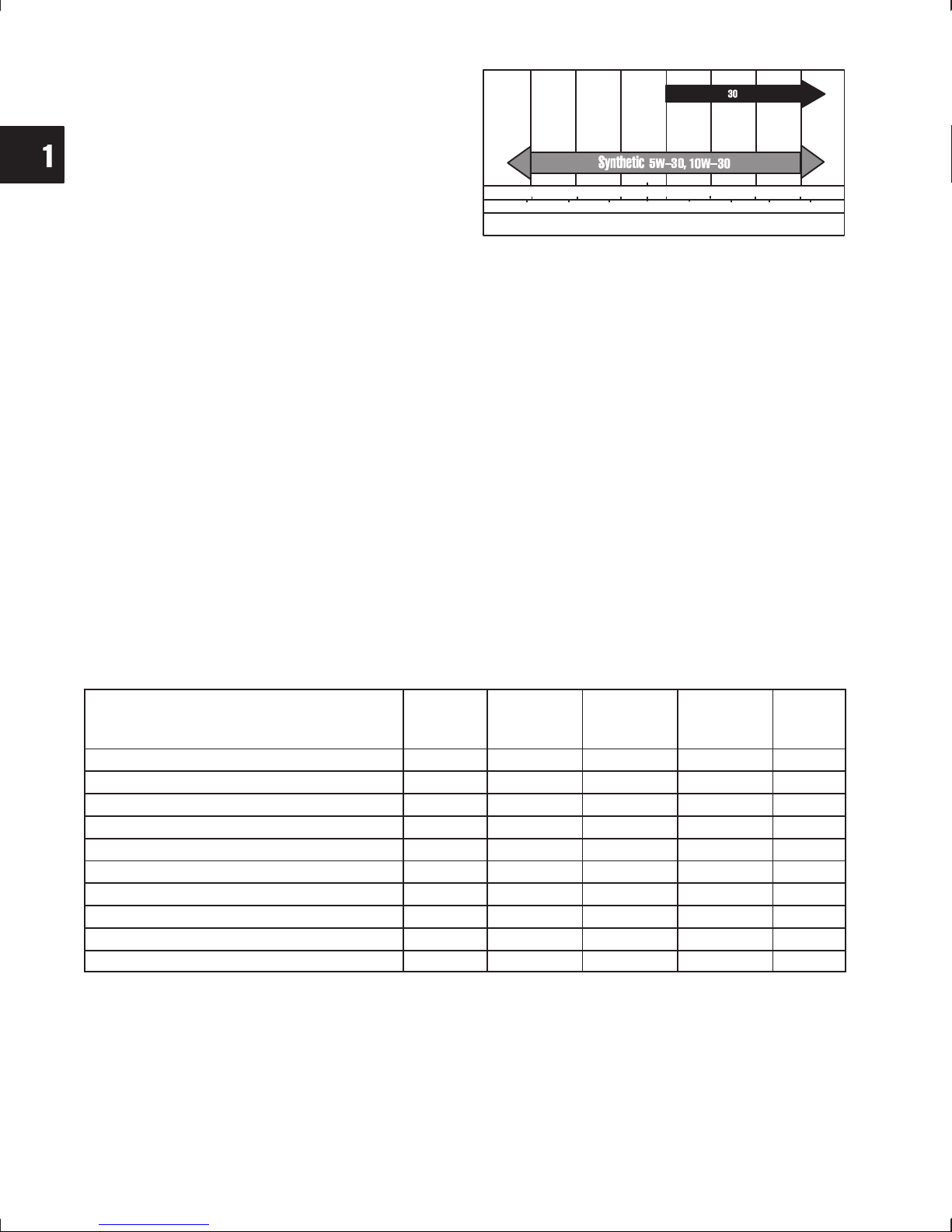
**
-20 0
°F
-30
°C
STARTING TEMPERATURE RANGE ANTICIPATED BEFORE NEXT OIL CHANGE
-20 -10 0 10 20 30 40
20 40 60 80 100
32
Air cooled engines run hotter than automotive
engines. Use of multi-viscosity oils (10W-30,
etc.) in ambient temperatures above 40 F
(4C) will result in high oil consumption. If
multi-viscosity oil is used, check oil level more
frequently to prevent any possible engine
damage due to lack of lubrication.
** SAE 30 oil, if used in ambient temperatures
below 40 F (4 C) will result in hard starting
and possible engine damage due to inadequate lubrication.
Synthetic oil meeting ILSAC GF-2, API certification mark and API service symbol with “SJ/
CF ENERGY CONSERVING” rating or higher,
is an acceptable oil at all temperatures.
NOTE: Use of synthetic oil does not alter
the required oil change intervals.
MAINTENANCE & ADJUSTMENTS SCHEDULE
The following maintenance schedule is a general guide. See the Engine Operating & Maintenance Instructions
for details on specific engine models.
25 Hours
or Every
Season
Note #2
Maintenance Schedule
Check oil level *
Change oil
Change oil filter
Clean/Replace air filter pre-cleaner
Clean/Replace air filter cartridge
Clean cooling system
Inspect/clean spark arrester (if used)
Replace or clean spark plugs
Replace in-line fuel filter
Remove combustion chamber deposits
8 Hours
or Daily
* Change oil after the first 5 to 8 hours of operation (break-in period), then after every 50 hours or every season.
NOTE: #1 – Change oil every 25 hours when operating under heavy load or in high temperatures.
50 Hours
or Every
Season
Note #1
100 Hours
or Every
Season
Note #2
Note #2
500
Hours
NOTE: #2 – Clean more often under dusty conditions or when airborne debris is present. Replace air cleaner
parts when dirty.
8
Page 10

AIR CLEANER SERVICE
AVOID FIRES!
1LOCKED FOR PRINTING – SELECT SECT. NEEDED >
WARNING
• Never operate an engine with the air cleaner
assembly or air cleaner cartridge removed!
A properly serviced air cleaner protects internal engine parts from airborne dirt and dust particles. If air
cleaner instructions are not followed, particles that
should be collected in the air cleaner will pass into
the engine. These particles are abrasive and will
cause the piston rings and cylinder bore to wear
quickly. As the rings and bore wear, the abrasive particles enter the crankcase and contaminate the oil,
forming an abrasive mixture that will wear internal
parts.
Examine the air cleaner on every engine brought in
for a check up or repair. If the air cleaner shows signs
of neglect, show it to the customer before cleaning.
Instruct the customer on proper care to assure long
engine life.
NOTE: Replace worn or damaged air cleaner gas-
kets and mounting gaskets to prevent dirt
and dust from entering engine through improper sealing. Replace air cleaner mounting bracket if bent.
Fig. 1
Remove and service foam pre-cleaner, if equipped,
every 25 hours or every season, whichever occurs
first. Service cartridge every 100 hours or every season, whichever occurs first.
NOTE: Service air cleaner more often under dusty
conditions.
Round Air Cleaner
1. Remove cover (1), knob (2), plate (3), and air
cleaner cartridge (4) with pre-cleaner (5), Fig. 1
or Fig. 2.
Fig. 2
2. Remove foam pre-cleaner from cartridge.
3. Wash pre-cleaner in liquid detergent and water.
4. Squeeze dry in a clean cloth. Set aside.
5. Inspect cartridge. Replace if damaged or dirty.
9
Page 11

1
CAUTION: DO NOT use petroleum solvents to
clean paper cartridge.
DO NOT oil paper cartridge.
DO NOT use pressurized air to clean or dry paper
cartridge.
6. Reinstall pre-cleaner over cartridge.
7. Install cartridge to air cleaner.
8. Install plate, knob and air cleaner cover.
Square Air Cleaner
1. Remove knob(s) (2) and cover assembly (1),
Fig. 3.
Cyclonic Air Cleaner
NOTE: The debris valve automatically discharges
dust and debris. There should be minimal
debris for removal.
1. Remove debris from the air cleaner by
squeezing the ends of the debris valve (5),
Fig. 4.
Fig. 3
2. Remove cartridge (4) and pre-cleaner (5) from
cover.
3. Wash pre-cleaner in liquid detergent and water.
4. Squeeze dry in a clean cloth. Set aside.
5. Inspect cartridge. Replace if damaged or dirty.
CAUTION: DO NOT use petroleum solvents to
clean paper cartridge.
DO NOT oil paper cartridge.
DO NOT use pressurized air to clean or dry paper
cartridge.
6. Install pre-cleaner in cover with foam toward
cover. (Nylon screen toward paper element.)
Fig. 4
2. Remove the cover (4) from the air cleaner
housing (1).
3. Remove the primary filter (3) and inspect.
Replace the filter if damaged, or dirty.
CAUTION: DO NOT clean or oil these filters.
DO NOT use pressurized air to clean or dry filters.
REPLACE filters if damaged or dirty
4. Inspect the safety filter (2).
NOTE: DO NOT remove the safety filter (2) as part
of the inspection.
If it is necessary to remove the safety filter,
Fig. 5, be sure all debris is removed from the
air cleaner housing before removal.
Replace the safety filter with every third
replacement of the primary filter, or if
damaged or dirty.
7. Install paper cartridge in cover with tabs on
cartridge (3) in slots of cover, Fig. 3.
8. Reinstall cover assembly on air cleaner body.
10
5. Reinstall filter(s).
6. Reinstall air cleaner cover.
Page 12

1LOCKED FOR PRINTING – SELECT SECT. NEEDED >
CARBURETOR ADJUSTMENTS
Models 290000 – 350000
The Vanguard OHV twin cylinder engine carbure-
tor fuel mixture adjustment procedure is unique. Perform adjustments exactly in the sequence shown.
NOTE: If engine is equipped with Performance
Control electronic governor see separate
adjustment procedure.
Initial Adjustment
Fig. 5
ARMATURE AIR GAP ADJUSTMENT
1. Loosen screws holding armature in place. Slide
armature away from flywheel and tighten one of
the screws.
2. Rotate flywheel until magnet is under armature
laminations.
3. Place thickness gauge (1) between magnet and
armature laminations, Fig. 6.
• All EXCEPT Models 540000, 610000 – Use
0.008” – 0.012” (0.20 – 0.30 mm) gauge.
• Models 540000, 610000 – Use 0.005 – 0.007”
(0.13 – 0.18 mm) gauge.
1. Turn idle mixture screw (1), Fig. 7, CLOCKWISE
until it just seats. DO NOT FORCE.
2. Turn valve COUNTERCLOCKWISE 1-1/4
turns.
This setting will permit engine to start. Final adjustment will be made with engine running.
NOTE: Parts removed for clarity.
Fig. 6
4. Loosen screw on the armature. Allow armature
to be pulled against the gauge by the flywheel
magnet. Tighten both armature screws to 25 in.
lbs. (3 Nm).
5. Rotate flywheel to remove gauge.
6. Repeat procedure for the other armature.
Fig. 7
If engine is equipped with a secondary governor
spring, Fig. 8, check governor lever adjustment
procedure before starting engine.
(1) Primary Governor Spring
(2) Loop (faces UP)
(3) Secondary Governor Spring
(4) Loop Over Tab
(5) #2 Hole (Generators)
(6) #1 Hole (Remote Control)
11
Page 13

1
Ì
Fig. 8
Final Adjustment
All carburetor adjustments performed with the engine running must be made with the air cleaner
installed.
• Tools Required, Fig. 9:
Tachometer #19200 or #19389
Fig. 10
4. Turn idle mixture screw slowly CLOCKWISE (1)
until engine speed just starts to slow (LEAN
mixture), Fig. 11.
Tang Bender #19352
1. Start engine. Run for approximately 5 minutes to
allow engine to warm up.
2. Move control lever on equipment to SLOW
position.
1938919200
19352
Fig. 9
3. Hold throttle lever (2) against idle speed screw
(1), Fig. 10. Temporarily adjust idle to RPM
shown below.
Fig. 11
5. Then turn idle mixture screw COUNTERCLOCKWISE (3) until engine speed just starts to
slow (RICH mixture).
6. Turn screw to mid point (2) between RICH and
LEAN.
7. Hold throttle lever against idle speed adjustment
screw and re-adjust idle to RPM shown below:
a. 1200 RPM – Governed Idle Spring #805453
(RED).
b. 900 RPM – Governed Idle Spring #805454
(WHITE).
8. Release throttle lever. Note RPM.
9. If necessary bend governed idle tang (5) with
Tang Bender #19352 (4), Fig. 12, to obtain RPM
shown:
a. 1400 RPM – Governed Idle Spring #805453
(RED).
b. 1100 RPM – Governed Idle Spring #805454
(WHITE).
12
a. 1750 RPM – Governed Idle Spring #805453
(RED).
b. 1100 RPM – Governed Idle Spring #805454
(WHITE).
Page 14

1LOCKED FOR PRINTING – SELECT SECT. NEEDED >
10. If the carburetor is equipped with an idle mixture
limiter cap install it at this time.
a. Position limiter cap (7) so that stop(s) on
limiter cap are at mid point between stop(s)
on carburetor body, Fig. 13.
Fig. 12
Fig. 14
Performance Control Engines
NOTE: All carburetor adjustments with engine
running must be made with the air cleaner
correctly installed.
1. Start engine and run it for approximately 5
minutes to allow engine to reach operating
temperature.
2. Activate idle down device, or ground BLUE wire
(1) from control module using a jumper wire (2),
Fig. 15.
3. Temporarily adjust idle speed to 1400 RPM.
Fig. 13
b. Press limiter into position using Knock Out
Pin, #19135 (6) as shown.
11. With equipment control lever in SLOW position
and engine running at governed idle, use Tang
Bender, #19352 (9), to bend throttle restrictor
tang (8) so that tang just contacts governor lever
(10), Fig. 14.
12. Move equipment control to FAST position.
Engine should accelerate smoothly.
Re-adjust idle mixture valve 1/8 turn richer if
necessary.
Fig. 15
4. Turn idle mixture screw slowly CLOCKWISE (3)
until engine speed just starts to slow (LEAN
mixture), Fig. 16.
5. Then turn idle mixture valve COUNTERCLOCKWISE (5) until engine speed just starts to slow
(RICH mixture).
6. Turn valve to mid point (4) between RICH and
LEAN.
7. Re-adjust idle speed to 1750 RPM.
13
Page 15

1
NOTE: Idle speed may vary according to OEM
specifications.
Fig. 16
8. Deactivate idle-down device, or remove jumper
wire. Engine should accelerate smoothly to top
governed speed. Re-adjust idle mixture screw
1/8 turn richer if necessary.
9. If the carburetor is equipped with an idle mixture
limiter cap, install it at this time.
a. Position limiter cap (7) so that stop on limiter
cap is at mid point between stops on
carburetor body, Fig. 17.
Fig. 18
2. Then turn screw COUNTERCLOCKWISE 3/4
turn.
Fig. 17
b. Press limiter into position using Knock Out
Pin #19135 (6).
Models 351400, 380400, 351700 and 380700
The OHV twin cylinder engine carburetor fuel
mixture adjustment procedure is unique. Perform
adjustments exactly in the sequence shown.
Horizontal crankshaft engines (1) and vertical
crankshaft engines (2) are shown in Fig. 18.
Initial Adjustment
3. Repeat for #2 cylinder.
This setting will permit engine to start. Final adjustment will be made with engine running.
Final Adjustment
Carburetor adjustments performed with engine running must be made with the air cleaner correctly
installed.
NOTE: Idle mixture adjustment MUST be per-
formed with the engine running at 1200
RPM.
Tools Required:
• Tachometer #19200 or #19389
• Tang Bender #19352
1. Start engine and run it for approximately 5
minutes to allow engine to reach operating
temperature.
2. Move equipment control lever to SLOW
position.
1. Turn idle mixture screw for #1 cylinder CLOCKWISE until it just seats. DO NOT FORCE,
Fig. 18.
14
3. Hold throttle lever (1) against idle speed screw
(2), Fig. 19. Temporarily adjust idle to 1200
RPM.
Page 16

1LOCKED FOR PRINTING – SELECT SECT. NEEDED >
4. While holding throttle lever, SLOWLY turn idle
mixture screw for #1 cylinder CLOCKWISE until
engine speed just starts to slow (LEAN mixture).
Fig. 19
5. Then turn idle mixture screw (3) COUNTER-
CLOCKWISE 3/8 turn, Fig. 20.
NOTE: It may be necessary to re-adjust idle speed
to 1200 RPM before proceeding.
a. 1750 RPM – Governed Idle Spring #805453
(RED).
b. 1100 RPM – Governed Idle Spring #805454
(WHITE).
NOTE: Parts removed for clarity.
Fig. 21
10. If carburetor is equipped with idle mixture limiter
caps, install at this time.
6. Adjust idle mixture screw for #2 cylinder as
described in steps 4 and 5.
7. If necessary, re-adjust idle speed screw to RPM
shown below.
a. 1200 RPM – Governed Idle Spring #805453
(RED).
b. 900 RPM – Governed Idle Spring #805454
(WHITE).
8. Release throttle lever. Note RPM.
Fig. 20
9. If necessary, use Tang Bender #19352 (6),
Fig. 21. Bend governed idle tang LEFT to
INCREASE (4), right to DECREASE (5) engine
speed to obtain RPM shown:
a. Position limiter cap (8) so that stop on limiter
cap is at mid point between stops on carburetor body. Press limiter into position using
Knock Out Pin #19135 (7) as shown in,
Fig. 22.
b. Repeat for other idle mixture valve.
11. With equipment control lever in SLOW position
and engine running at governed idle, use Tang
Bender #19352 (10), to bend throttle restrictor
tang (9) so that it just contacts governor lever
(11), Fig. 23.
12. Move equipment control to FAST position.
Engine should accelerate smoothly. Re-adjust
idle mixture valve 1/8 turn richer if necessary.
Fig. 22
15
Page 17

1
Remove deposits from combustion chamber and
around valves using a wire brush or scraper. With
piston at Top Dead Center (TDC), remove
combustion chamber deposits from top of piston.
Use care to prevent combustion chamber deposits
from entering push rod or oil return cavity in cylinder.
Take care not to damage cylinder, top of piston,
cylinder head and cylinder head gasket surfaces.
11
Fig. 23
Choke Control Adjustment
NOTE: Be sure choke control wire is installed in #2
hole (2) in choke lever, Fig. 24.
Fig. 24
1. Place choke control lever on equipment in
CHOKE position.
NOTE: Remove only the combustion chamber de-
posits. It is not necessary to remove the discoloration marks on the piston, valves and
cylinder head. These marks are normal and
will not affect engine operation.
Remove the loose deposits from around the top ring
land area using compressed air or a soft bristle
brush.
Cooling System Cleaning
Grass particles, chaff or dirt can clog the air cooling
system, especially after prolonged service in cutting
dry grass or very dirty air. Operating with a clogged
cooling system can cause overheating and engine
damage. Cleaning the cooling system should be a
regular maintenance operation, performed yearly or
every 100 hours, whichever comes first.
All Except Models 540000, 610000
Fig. 25 shows the blower housing removed and
areas to be cleaned (1) on the Vanguard engine.
2. Loosen control casing clamp screw (4).
3. Move control casing and wire (3) until choke is
completely closed (1).
4. Tighten casing clamp screw.
Combustion Chamber Deposits
Combustion chamber deposits should be removed
every 500 hours or whenever cylinder heads are
removed.
WARNING
AVOID EYE INJURY!
• Wear eye protection whenever using
compressed air to clean parts.
16
Fig. 25
Page 18

1LOCKED FOR PRINTING – SELECT SECT. NEEDED >
Ì
Models 540000, 610000
1. Use a coin or screwdriver to twist the Easy Clean
Access panel fasteners (1), Fig. 26
COUNTERCLOCKWISE until a CLICK is heard
(approx. 3/4 turn).
2. Remove the panel (2).
Fig. 26
3. Blow compressed air from the PTO side to clean
the cooling fins (3), Fig. 27 around each cylinder
and to back flush the cooling system.
Fig. 28
Fig. 29
Fig. 27
4. Insert the access panel tab into the blower housing slot. Be certain the access panel is correctly
engaged to the blower housing. Push the panel
completely into the housing. Twist each fastener
CLOCKWISE until it “CLICKS”, approx. 3/4 turn.
CAUTION: DO NOT run the engine unless the
Easy Clean Access panel is correctly installed.
Crankcase Oil
Change Oil and Filter
Drain oil while the engine is still warm. See Fig. 28
for approximate drain plug locations on vertical
crankshaft engines; Fig. 29 for horizontal crankshaft
engines.
1. Remove oil drain plug (1). Drain oil into
approved container.
2. Remove dipstick.
3. Replace oil filter (2) every 100 hours. Before
installing new filter, lightly oil filter gasket with
new engine oil.
4. Screw filter on CLOCKWISE (arrow) by hand
until gasket contacts filter adapter. Hand tighten
an additional 1/2 - 3/4 turn.
5. Replace drain plug.
6. Refill crankcase slowly with new oil of proper
service classification and viscosity grade. Refill
to FULL mark on dipstick.
CAUTION: DO NOT OVERFILL THE ENGINE
WITH OIL!
17
Page 19

1
The crankcase capacity of Vanguard V-Twin
engines is approximately:
• All (except Model 540000) – 48 oz. (1.4
liters) with filter
• Models 540000, 610000 – 79 oz. (2.3
liters) with filter
• Models 540000, 610000 – 71 oz. (2.1
liters) without filter
NOTE: When checking oil level, screw the dipstick
all the way in for accurate readings.
7. Start engine. Run at IDLE for 30 seconds and
stop engine. Recheck oil level and add if
required. Restart engine and check for oil leaks.
Governor Adjustments
CAUTION
AVOID INJURY! Complete the
governor static adjustment BEFORE
starting or running engine.
CAUTION:
2. Use a screwdriver (2) to rotate governor shaft
COUNTERCLOCKWISE as far it will go. Torque
governor nut to 70 in. lbs. (8 Nm).
3. Install throttle and choke control cables and
check for proper operation.
Dynamic Governor Adjustment
NOTE: Carburetor mixture adjustments must be
• Tools Required, Fig. 31:
Tachometer #19200 (1) or #19389 (3)
Tang bender #19352 (2)
Do not bend governor link or distort
governor lever.
made before adjusting governed idle,
throttle restrictor and top no-load RPM.
• Incorrect adjustment could result in engine
overspeeding, causing engine damage,
property damage or personal injury.
Static Governor Adjustment
(Before Running Engine)
1. Loosen governor lever nut. Push on governor
lever (1) until throttle is wide open, Fig. 30.
Fig. 31
Manual Friction and Remote Speed Controls
Governor spring is installed in #1 hole (3) in governor
lever, Fig. 32.
Start and run engine for approximately 5 minutes to
allow engine to warm up.
1. Move control lever to SLOW position.
2. Use tool #19352 (1) to bend governed idle tang
(2) to obtain RPM shown:
Fig. 30
18
a. 1750 RPM – Governed Idle Spring #805453
(RED).
b. 1100 RPM – Governed Idle Spring #805454
(WHITE).
Page 20

1LOCKED FOR PRINTING – SELECT SECT. NEEDED >
Fixed Speed Adjustable – Except Generators
Governor spring is installed in #1 hole in governor
lever (3), Fig. 35.
Start and run engine for approximately 5 minutes to
allow engine to warm up.
1. Turn fixed speed adjustable control nut counterclockwise until control swivel contacts slow
speed stop.
3. With equipment control lever in SLOW position
and engine running at governed idle RPM, use
Tang Bender #19352 (1), to bend throttle
restrictor tang (4) so that it just contacts
governor lever (5), Fig. 33.
Fig. 32
Fig. 33
4. Refer to Service Engine Sales Microfiche,
MS-6225 or the Service Engine Sales Manual,
MS-4052, for Top No-Load RPM by engine
Model and Type Number.
5. Move control throttle lever to FAST position and
check engine RPM.
6. Use Tool #19352 (1) to bend tang (6) UP (7) to
increase and DOWN (8) to decrease engine
speed, to obtain desired Top No-Load RPM,
Fig. 34.
NOTE: Air cleaner removed for clarity.
2. Use Tool #19352 (1) to bend governed idle tang
(2) to obtain RPM shown:
a. 1750 RPM – Governed Idle Spring #805453
(RED).
b. 1100 RPM – Governed Idle Spring #805454
(WHITE).
Fig. 35
3. Use Tool #19352 (1) to bend throttle restrictor
tang (4) so that it just contacts governor lever (5),
Fig. 36.
Fig. 34
Fig. 36
NOTE: Be sure the governor spring is installed in #1
hole in governor lever (9), Fig. 37.
4. Refer to Service Engine Sales Microfiche,
MS-6225 or the Service Engine Sales Manual,
MS-4052, for Top No-Load RPM by engine
Model and Type Number.
19
Page 21

1
5. Turn fixed speed adjustable control nut (6)
clockwise (8) to increase or counter-clockwise
(7) to decrease engine speed until desired Top
No-Load RPM is obtained, Fig. 37.
Fig. 37
Fixed Speed Adjustable – Generators
No governed idle spring is used with this system. No
throttle restrictor adjustment is necessary. The
primary governor spring (1) is installed in #2 hole on
governor lever (5). A secondary governor spring (3)
is installed with loop (4) over the governor lever tab
(4), and the rear loop facing (2) UP as shown in
Fig. 38.
Adjust Secondary Governor Spring
1. Disengage the adjustable fixed speed control
nut (Inset, Fig. 40).
2. Loosen and remove fixed speed adjustable
control nut, spring and retainer.
3. Rotate governor control swivel (1) counterclockwise to end of travel, Fig. 39.
4. Install Adjustment Gauge #19385 (3), with notch
over end of governor lever and flat end of tool
against governor control bracket as shown in
Fig. 39.
5. Hold gauge in position and bend tab (5) with Tang
Bender #19352 (4) so that all slack is removed
from secondary governor spring (2) between its
two anchor points, Fig. 39. DO NOT STRETCH
SPRING.
6. Remove adjustment gauge.
NOTE: Secondary governor spring must be
adjusted BEFORE the engine is started.
Perform adjustment in the sequence
shown.
Fig. 38
Fig. 39
Start engine. Run for approximately 5 minutes to
allow engine to warm up.
7. With engine running, pull control rod (7) out until
swivel is against stop. Hold in this position,
Fig. 40.
8. Use tang bender (4) to bend tang (6). Adjust to
Top No-Load RPM for the type of generator
listed in Table 1.
9. Re-install control nut, spring and retainer. Turn
nut clockwise until threads on control rod are
visible from end of nut, inset Fig. 40.
20
Page 22

1LOCKED FOR PRINTING – SELECT SECT. NEEDED >
TABLE NO. 1
Generator
Type
3600 RPM
60 Cycle
3000 RPM
50 Cycle
Top No-Load
RPM
4250 RPM 3750 RPM
3600 RPM 3150 RPM
Regulated
No-Load RPM
Fig. 40
10. Engage fixed speed adjustable control nut (8)
and adjust to Regulated No-Load RPM for the
type of generator listed in Table 1, Fig. 41.
a. Turn nut CLOCKWISE (10) to increase
speed.
b. Turn nut COUNTERCLOCKWISE (9) to
decrease speed.
NOTE: Final adjustment should be made with
generator loaded to rated capacity or to
manufacturer’s specifications.
Adjust Secondary Governor Spring
1. Move equipment control to SLOW position.
2. Install Adjustment Gauge #19385 (4), with notch
over end of governor lever and flat end of tool
against governor control bracket as shown in
Fig. 42.
3. Hold gauge in position and bend tab (2) with Tang
Bender #19532 (1), so that all slack is removed
from secondary governor spring (5) between its
two anchor points, Fig. 42. DO NOT STRETCH
SPRING.
4. Remove adjustment gauge.
Fig. 41
Remote Speed Control Engines Equipped With
Secondary Governor Spring
Some Vanguard OHV V-Twin engines with remote
speed control are equipped with a secondary governor spring (5). The primary governor spring is
installed in #1 hole (3) on governor lever, Fig. 42.
NOTE: The secondary governor spring must be
adjusted BEFORE the engine is started.
Perform the adjustment in the sequence
shown.
Start engine. Run for approximately 5 minutes to
allow engine to warm up.
5. Move control lever to SLOW position.
6. Use tang bender (1) to bend governed idle tang
(6) to obtain RPM shown, Fig. 43:
a. 1750 RPM – Governed Idle Spring #805453
(RED).
b. 1100 RPM – Governed Idle Spring #805454
(WHITE).
NOTE: Engine Model 303447 Type 0411-01 – Set
governed idle to 1350 RPM 50 RPM.
Fig. 42
21
Page 23

1
7. With equipment control lever in SLOW position
and engine running at governed idle RPM, use
Tang Bender #19352 (1), and bend throttle
restrictor tang (7) so that tang just contacts
governor lever (8), Fig. 44.
Fig. 43
Fig. 45
Oil Cooler
Some engines are equipped with an oil cooler,
Fig. 46. The oil cooler is mounted on the blower
housing. Filtered oil is routed through the oil cooler
through two oil lines from a special oil filter adapter.
Forced air from the flywheel fan flows through the oil
cooler fins dissipating heat from the engine oil.
The oil cooler fins should be cleaned every 100
hours, checked periodically for debris, and cleaned
with compressed air or a soft bristle brush.
Fig. 44
8. Refer to Service Engine Sales Microfiche,
MS-6225 or the Service Engine Sales Manual,
MS-4052, for Top No-Load RPM by engine
Model and Type Number.
9. Move control throttle lever to FAST position and
check engine RPM.
10. Bend tang (8) with Tool #19352 (1) to obtain desired top no-load RPM, Fig. 45.
NOTE: Engine Model 303447 Type 0411-01 – Set
Top No-Load Speed to 2900 RPM 50
RPM.
22
Fig. 46
Spark Plugs
Replace spark plugs every 100 hours of operation or
every season, whichever occurs first. Replace spark
plugs if electrodes are burned away, or if the
porcelain is cracked.
NOTE: Do not blast-clean spark plugs. Spark plugs
should be cleaned by scraping or hand wire
brushing and washing in a commercial
solvent.
Use a wire gauge (1) to set spark plug gap, Fig. 47.
Torque spark plugs to 180 in. lbs. (20 Nm).
Page 24

1LOCKED FOR PRINTING – SELECT SECT. NEEDED >
Fig. 47
All Except Models 540000, 610000
Resistor spark plugs recommended by Briggs &
Stratton:
• B&S #491055 (Champion RC12YC) or
• B&S #496018 (Champion RC14YC)
Gap to 0.030” (0.76 mm).
FAST
SLOW
Fig. 48
Valve Clearance Adjustment
1. Set No. 1 cylinder at 1/4” (6 mm) past TDC,
compression stroke.
Models 540000, 610000
Resistor spark plug recommended by Briggs &
Stratton:
• B&S #692051
Gap to 0.020” (0.51 mm).
Speed Control Wire Adjustment
NOTE: Manual friction and remote control
adjustment procedure is identical.
1. Loosen control casing clamp screw (1) at
governor control bracket, Fig. 48.
2. Move speed control lever to FAST position (in-
set, Fig. 48).
3. Move control casing and wire until governor
control swivel is at end of travel.
2. Use a feeler gauge (1) to measure the valve
clearance. Valve clearance should be 0.005”
(0.13 mm) for the intake and exhaust valve.
NOTE: Measure valve clearance with the engine
COLD.
3. If the valve clearance requires adjustment,
loosen the lock nut (2) with a wrench (4). Use a
hex wrench (5) to turn the adjusting screw (3) to
adjust the valves, Fig. 49.
4. With the valve clearance correctly adjusted,
hold the adjusting screw. Torque the lock nut to
70 in. lbs. (8 Nm).
5. Repeat for No. 2 cylinder.
4. Tighten casing clamp screw.
Fig. 49
23
Page 25

1
TUNE-UP PROCEDURE
A “Tune-Up,” see the steps listed below, would normally be performed on relatively new engines brought in for
minor difficulties. By performing these steps you will either be sure that the engine is functioning properly or will
know what major repairs should be made. The steps are also covered in the Overhaul Procedure and will normally
be performed as a part of the complete overhaul.
1. Disconnect and ground spark plug wires.
2. Remove air cleaner cartridge, check for proper
servicing. Check gaskets, pre-cleaner and
cartridge for damage.
3. Check oil level. Drain oil. Remove oil filter.
4. Remove blower housing, inspect rewind
assembly when equipped.
touch flywheel. Check ground wire and stop
switch connections.
10. Remove cylinder heads. Remove carbon.
Check head gaskets. Inspect valves for seating.
11. Install cylinder heads and new gaskets. Tighten
to specified torque. Adjust valve clearance. Set
spark plug gaps.
5. Clean cooling fins and entire engine.
6. Check governor, linkage and springs for
damage and wear. Check governor adjustment.
7. Remove intake manifold and carburetor.
Disassemble carburetor. Wash in solvent and
inspect for wear or damage. Replace gaskets
and parts as necessary. Reinstall carburetor on
manifold. Set initial adjustment.
8. Replace spark plugs. Remove flywheel. Check
flywheel key. Check for oil seal leakage on both
flywheel and PTO sides.
9. Check coils. Inspect all wires for breaks and/or
damaged insulation. Be sure ground wires do not
12. Reinstall intake manifold using new gaskets.
13. Reinstall blower housing.
14. Install new oil filter. Replace oil and fuel.
15. Adjust equipment control and cables, if used, for
correct operation.
16. Service air cleaner pre-cleaner and cartridge, or
replace.
17. Check muffler for restrictions or damage.
18. Start engine and bring up to operating
temperature. Then, adjust carburetor mixture
and engine top speed.
OVERHAUL PROCEDURE
The following Overhaul Procedure is intended to help you to establish a systematic method of repairing Briggs
& Stratton OHV engines. These steps may be performed in a different order but best efficiency is obtained when
the repairs are performed in the same sequence every time. The exact procedure will vary according to the engine
model being repaired. Be careful to locate the instructions covering the specific model being repaired.
Disassemble
1. Drain oil. Remove oil filter.
2. Remove spark plugs.
3. Air cleaner assembly (if equipped).
Fuel tank and bracket assembly (if equipped).
Fuel pump and bracket (if equipped).
4. Rotating screen (if equipped). Blower housing.
5. Rewind starter (if equipped).
6. Exhaust manifold, muffler(s).
7. Intake manifold and carburetor.
8. Check throttle shaft and bushings for wear.
9. Disassemble carburetor.
10. Check armature air gap. Remove armatures.
11. Flywheel.
12. Electric starter.
13. Breather. Valve covers and valley cover.
14. Governor control bracket.
15. Check valve clearances.
16. Cylinder shields, rocker arms, push rods,
cylinder heads.
17. Valves, springs and seals. Inspect valve guides
and seats.
18. Check crankshaft end play. Remove burrs from
crankshaft extension.
19. Crankcase cover. Inspect bearings. Remove oil
seal.
20. Cam gear and tappets. Inspect governor.
21. Connecting rods and pistons.
22. Inspect crankshaft.
24
Page 26

1LOCKED FOR PRINTING – SELECT SECT. NEEDED >
23. Cylinder – check cylinder bores and bearings.
Remove oil seal.
24. Disassemble and check connecting rods,
pistons, piston pins and rings.
25. Disassemble and inspect oil pump.
Inspection and Repairs
1. Clean parts.
2. Resize cylinder bore as required.
3. Replace main bearing.
4. Replace all oil seals.
5. Replace valve guides.
6. Reface and lap valves and seats.
7. Replace armatures.
8. Repair carburetor.
9. Replace rewind starter spring and rope (if
equipped)
Reassemble
1. Crankshaft.
2. Pistons, piston pins, rings and connecting rods.
3. Tappets, cam gear.
4. Mechanical governor.
5. Oil pump.
6. Crankcase cover – check end play. Replace oil
seal.
7. Electric starter.
8. Flywheel and starter pulley (if equipped).
9. Armatures – adjust air gap.
10. Check spark.
11. Valves, seals, springs and retainers.
12. Cylinder heads, push rods, rocker arms and
cylinder shields.
13. Adjust valve clearance.
14. Valve covers, breather and valley cover.
15. Linkage and governor controls.
16. Carburetor and intake manifold.
17. Check and adjust mechanical governor.
18. Blower housing.
19. Fuel pump and bracket (if equipped).
Fuel tank and bracket (if equipped).
20. Clean and assemble air cleaner.
21. Exhaust manifold, mufflers.
22. Install new spark plugs.
23. Replace oil filter. Fill crankcase with oil. Fill with
gas. Start engine.
24. Adjust carburetor.
25. Adjust governor controls to obtain correct
engine speed (remote controls).
26. Re-torque cylinder head screws.
27. Spray paint engine and apply decals.
25
Page 27

1
26
Page 28

2LOCKED FOR PRINTING – SELECT SECT. NEEDED >
Section 2
Troubleshooting
Page
ELECTRICAL SYSTEMS 32. . . . . . . . . . . . . . . . . . . . . . . . . . . . . . . . . . . . . . . . . . . . . . . . . . . . . . . . . . . .
Alternators 32. . . . . . . . . . . . . . . . . . . . . . . . . . . . . . . . . . . . . . . . . . . . . . . . . . . . . . . . . . . . . . . . . . . . . .
Alternator System Diagnosis 32. . . . . . . . . . . . . . . . . . . . . . . . . . . . . . . . . . . . . . . . . . . . . . . . . . . .
Charging System Identification 33. . . . . . . . . . . . . . . . . . . . . . . . . . . . . . . . . . . . . . . . . . . . . . . . . .
Flywheel Magnet Identification 34. . . . . . . . . . . . . . . . . . . . . . . . . . . . . . . . . . . . . . . . . . . . . . . . . .
Equipment Used to Test Alternators 34. . . . . . . . . . . . . . . . . . . . . . . . . . . . . . . . . . . . . . . . . . . . . .
Testing Alternator Output 35. . . . . . . . . . . . . . . . . . . . . . . . . . . . . . . . . . . . . . . . . . . . . . . . . . . . . . . .
AC Alternator 35. . . . . . . . . . . . . . . . . . . . . . . . . . . . . . . . . . . . . . . . . . . . . . . . . . . . . . . . . . . . . . . . .
DC Alternator 36. . . . . . . . . . . . . . . . . . . . . . . . . . . . . . . . . . . . . . . . . . . . . . . . . . . . . . . . . . . . . . . . .
Dual Circuit Alternator 37. . . . . . . . . . . . . . . . . . . . . . . . . . . . . . . . . . . . . . . . . . . . . . . . . . . . . . . . .
Tri-Circuit Alternator 38. . . . . . . . . . . . . . . . . . . . . . . . . . . . . . . . . . . . . . . . . . . . . . . . . . . . . . . . . . .
5 & 9 Amp Regulated Alternator 40. . . . . . . . . . . . . . . . . . . . . . . . . . . . . . . . . . . . . . . . . . . . . . . . .
10 & 16 Amp Alternator 41. . . . . . . . . . . . . . . . . . . . . . . . . . . . . . . . . . . . . . . . . . . . . . . . . . . . . . . .
20 Amp Regulated Alternator 43. . . . . . . . . . . . . . . . . . . . . . . . . . . . . . . . . . . . . . . . . . . . . . . . . . .
Powerlink System 45. . . . . . . . . . . . . . . . . . . . . . . . . . . . . . . . . . . . . . . . . . . . . . . . . . . . . . . . . . . . . . .
Anti-Afterfire Solenoid 47. . . . . . . . . . . . . . . . . . . . . . . . . . . . . . . . . . . . . . . . . . . . . . . . . . . . . . . . . . .
Testing Battery 48. . . . . . . . . . . . . . . . . . . . . . . . . . . . . . . . . . . . . . . . . . . . . . . . . . . . . . . . . . . . . . . . . .
Testing Engine Wiring Harness 50. . . . . . . . . . . . . . . . . . . . . . . . . . . . . . . . . . . . . . . . . . . . . . . . . . .
Oil Pressure 53. . . . . . . . . . . . . . . . . . . . . . . . . . . . . . . . . . . . . . . . . . . . . . . . . . . . . . . . . . . . . . . . . . . . .
Panel Kit with Key Switch and Solenoid 53. . . . . . . . . . . . . . . . . . . . . . . . . . . . . . . . . . . . . . . . . . .
Starter Motor 56. . . . . . . . . . . . . . . . . . . . . . . . . . . . . . . . . . . . . . . . . . . . . . . . . . . . . . . . . . . . . . . . . . . .
Conditions Affecting Starter Motor Performance 56. . . . . . . . . . . . . . . . . . . . . . . . . . . . . . . . . . .
Troubleshooting 56. . . . . . . . . . . . . . . . . . . . . . . . . . . . . . . . . . . . . . . . . . . . . . . . . . . . . . . . . . . . . .
Testing 56. . . . . . . . . . . . . . . . . . . . . . . . . . . . . . . . . . . . . . . . . . . . . . . . . . . . . . . . . . . . . . . . . . . . . .
Solenoid Test 57. . . . . . . . . . . . . . . . . . . . . . . . . . . . . . . . . . . . . . . . . . . . . . . . . . . . . . . . . . . . . . . . .
Performance ControlE Electronic Governor 58. . . . . . . . . . . . . . . . . . . . . . . . . . . . . . . . . . . . . . .
Wiring Diagram 58. . . . . . . . . . . . . . . . . . . . . . . . . . . . . . . . . . . . . . . . . . . . . . . . . . . . . . . . . . . . . . .
Governor Test 59. . . . . . . . . . . . . . . . . . . . . . . . . . . . . . . . . . . . . . . . . . . . . . . . . . . . . . . . . . . . . . . .
Replacing Actuator 59. . . . . . . . . . . . . . . . . . . . . . . . . . . . . . . . . . . . . . . . . . . . . . . . . . . . . . . . . . . .
EQUIPMENT PROBLEMS AFFECTING ENGINE OPERATION 64. . . . . . . . . . . . . . . . . . . . . . . . . . .
GASEOUS-FUELED ENGINES 61. . . . . . . . . . . . . . . . . . . . . . . . . . . . . . . . . . . . . . . . . . . . . . . . . . . . . . .
Troubleshooting Guide 61. . . . . . . . . . . . . . . . . . . . . . . . . . . . . . . . . . . . . . . . . . . . . . . . . . . . . . . . . .
Carburetor Adjustment 63. . . . . . . . . . . . . . . . . . . . . . . . . . . . . . . . . . . . . . . . . . . . . . . . . . . . . . . . . .
LPG-Only Operation 63. . . . . . . . . . . . . . . . . . . . . . . . . . . . . . . . . . . . . . . . . . . . . . . . . . . . . . . . . . . . .
SYSTEMATIC CHECK 28. . . . . . . . . . . . . . . . . . . . . . . . . . . . . . . . . . . . . . . . . . . . . . . . . . . . . . . . . . . . . . .
Ignition 28. . . . . . . . . . . . . . . . . . . . . . . . . . . . . . . . . . . . . . . . . . . . . . . . . . . . . . . . . . . . . . . . . . . . . . . . .
Carburetion 29. . . . . . . . . . . . . . . . . . . . . . . . . . . . . . . . . . . . . . . . . . . . . . . . . . . . . . . . . . . . . . . . . . . . .
Compression 29. . . . . . . . . . . . . . . . . . . . . . . . . . . . . . . . . . . . . . . . . . . . . . . . . . . . . . . . . . . . . . . . . . . .
27
Page 29

2
Most complaints concerning engine operation can be
classified as one or more of the following:
1. Will not start
2. Hard starting
3. Lack of power
4. Runs rough
5. Vibration
6. Overheating
7. High oil consumption
NOTE: What appears to be an engine problem may
actually be the fault of the powered
equipment. If equipment is suspect, see
Equipment Affecting Engine Operation.
SYSTEMATIC CHECK
A systematic check of the engine can be performed
in minutes, and is an accurate method of
determining the source of the problem. The basic
procedure is the same for all engine models.
Variations, by model, will be shown under the subject
heading. If the engine will not start and the cause is
not apparent, perform a systematic check in the
following order:
1. Ignition
2. Carburetion
Fig. 1
If there is NO SPARK look for –
1. Improperly operating equipment interlock
system
2. Shorted equipment stop switch wire
3. Two closed diodes in ground wire harness
(current style) or ground terminal (early style)
4. Incorrect armature air gap
5. Armature failure
3. Compression
Ignition
Test Using Electric Starter
NOTE: MagnetronR ignition systems require a
minimum of 350 RPM to produce spark.
WARNING
AVOID ELECTRICAL SHOCK!
• A partially sheared flywheel key will affect
ignition timing and engine performance.
• Spark can still occur with a sheared flywheel
key. A severe shock or kickback hazard may
exist.
With spark plugs installed, attach Ignition Tester
#19368 (1) to each spark plug lead (2). Ground the
other end of the tester as shown, Fig. 1. Spin the flywheel rapidly with engine starter. If spark jumps the
tester gap the ignition system is working correctly.
Test With Engine Running
If the engine runs, but misses under load, test the
ignition by installing an Ignition Tester #19368 (2)
between the spark plug lead (1) and each spark plug
(3), Fig. 2. A spark miss will be readily apparent
when the engine is running. If the spark appears
good in the tester but the engine misses, check for
a fouled spark plug.
Fig. 2
28
Page 30

2LOCKED FOR PRINTING – SELECT SECT. NEEDED >
Fouled Plug or Dead Cylinder
To test for a fouled spark plug or a non-functioning
cylinder, attach Ignition Tester #19368 (2) between
the spark plug lead (1) and each spark plug (4). With
engine running at top no-load speed, use a
screwdriver (3) with an insulated handle to ground
one spark plug by contacting the alligator clip on the
ignition tester to a good ground on the engine, Fig.
3. The engine should continue to run on the other
cylinder. Repeat this test with the other cylinder. If
the engine dies when performing this test, the
cylinder that is NOT grounded is not functioning
and/or the spark plug is fouled. Install a new spark
plug and re-check. If miss continues see the
following procedures.
If plugs are dry, look for –
1. Leaking carburetor mounting gaskets
2. Gummy or dirty carburetor, fuel line or tank
3. Float needle valve stuck shut
4. Inoperative fuel pump
5. Inoperative anti-afterfire solenoid
To determine if fuel is getting to the combustion
chamber through the carburetor, remove either
spark plug and pour a small quantity of gasoline
through the spark plug hole. Replace the spark plug.
If the engine fires a few times and then stops, look for
the same conditions as for a dry plug.
Compression
Compression Test
Briggs & Stratton does not publish compression
pressures, as it is difficult to obtain an accurate
reading without special equipment. An assessment
of the engine’s compression can be made as follows:
Fig. 3
Carburetion
NOTE: Gaseous fuel engines use carburetors that
must be serviced by a certified gaseous fuel
installer or by a certified dealer for the equipment powered.
Before performing a carburetion check, be sure the
fuel tank has an ample supply of fresh, clean gasoline. Be sure that the shutoff valve, if equipped, is
open and fuel flows freely through the fuel line before starting engine. Inspect and adjust the idle
needle valve. Make sure the choke closes completely. If engine will not start, remove and inspect
the spark plugs.
If plugs are wet, look for –
1. Overchoking
Remove both spark plugs and insert a compression
gauge into either cylinder (one cylinder at a time).
Turn engine over with engine starter until there is no
further increase in gauge pressure reading. Record
this reading. Repeat procedure on other cylinder and
record that reading. Divide the difference between the
cylinders by the compression pressure of the higher
of the two cylinders. A difference over 25% between
the cylinders indicates a loss of compression in the
cylinder with lower pressure. See example below.
Engine #1 Engine #2
Cylinder #1 65 PSI 75 PSI
Cylinder #2 60 PSI 55 PSI
Difference 5 PSI 20 PSI
% Difference 7.7% 26.7%
If compression is poor, look for –
1. Loose cylinder head bolts
2. Blown head gasket
3. Burned valves, burned and/or loose valve seats
4. Insufficient valve clearance
2. Excessively rich fuel mixture
3. Water in fuel
4. Float needle valve stuck open
5. Plugged air cleaner
5. Warped cylinder head
6. Warped valve stems
7. Worn bore and/or rings
8. Broken connecting rods
29
Page 31

2
Cylinder Leakdown Test
Use a leakdown tester to test the sealing capability
of each cylinder. Follow the instructions for the leakdown tester you are using to determine the likely
problem area(s).
1. Run engine for 5 minutes allowing engine to
reach operating temperature.
NOTE: If the engine is cold or cannot be started, air
flow may be higher (gauge readings lower)
because compression components are not
at normal operating temperatures.
2. Remove spark plug from engine. Disconnect
crankcase breather tube.
3. Rotate crankshaft in direction of operation until
piston is at Top Dead Center (TDC) of the compression stroke.
4. Hold flywheel nut with socket and breaker bar.
NOTE: Hold the crankshaft with the piston at TDC
to minimize the chance of rotation.
CAUTION
AVOID INJURY!
• Injury could occur if the crankshaft is
allowed to rotate or if the engine is not
securely fastened to a stand or to the
application.
Fig. 4
Cylinder Balance Test
If the engine starts hard, runs rough, misses or lacks
power, perform a cylinder balance test to determine
whether both cylinders are operating correctly.
A cylinder balance test will also detect a cylinder that
is not functioning. When grounding one cylinder
there will be no RPM loss. When the other cylinder
is grounded the engine will stop.
• Tools Required:
Tachometer #19200
Two @ Ignition Tester #19368
Screwdriver with insulated handle.
1. Attach Ignition Tester #19368 (2) between each
spark plug lead (1) and spark plug (3), Fig. 5.
5. Connect tester to a shop air source with
minimum air pressure of 70 psi (480 kPa).
6. Install outlet hose into spark plug hole of cylinder
being tested. Insure O-ring is seated to prevent
air leak at spark plug hole. Connect other end to
tester.
7. While securely holding the flywheel nut with the
breaker bar and socket, pull the adjustment
knob OUT (arrow), Fig. 4. Slowly turn the regulator adjustment knob (1) CLOCKWISE until tester
needle (2) is on the set point. Push in regulator
adjustment knob.
NOTE: Any air leaks at connections or fittings of
tester will affect the accuracy of test.
8. Slowly open the valve and note the reading on
the gauge.
30
Fig. 5
2. Start engine. Run at top no-load speed and note
spark at ignition testers. If the spark is equal at
both ignition testers, the problem is not ignition
related. A spark miss should be readily
apparent.
3. Note RPM of engine. Ground one cylinder with
screwdriver (4) by contacting alligator clip on
ignition tester to a good ground on engine,
Fig. 6. Note RPM loss.
Page 32

2LOCKED FOR PRINTING – SELECT SECT. NEEDED >
Conclusion: Cylinder #1 is weaker cylinder.
NOTE: A partially sheared flywheel key will affect
ignition timing and engine performance.
Fig. 6
4. Ground the other spark plug and again note the
RPM loss.
If the difference between the two cylinders does not
exceed 75 RPM, the amount of work the two
cylinders are doing is considered equal.
An RPM loss greater than 75 RPM indicates that the
cylinder with the lower RPM loss is the weaker of the
two cylinders. Look to that cylinder for a problem.
See example below.
Engine RPM – Both Cylinders = 3400 RPM
Engine RPM – Cylinder #1 Grounded = 3300 RPM
Problems Affecting One Cylinder
NOTE: A two cylinder engine will run on one
cylinder as long as the power required for
the application does not exceed the power
produced by one cylinder.
1. Spark plug – A fouled spark plug may also
indicate that carburetor is out of adjustment.
2. Spark plug wire
3. Head gasket
4. Intake manifold – A leak at either end of the
intake manifold will affect only one cylinder.
5. Valves
6. Rings
7. Piston
8. Cylinder
Problems Affecting Two Cylinders
1. Carburetion
2. Crankcase vacuum
Engine RPM – Cylinder #2 Grounded = 3100 RPM
3. Ignition timing
31
Page 33

2
ELECTRICAL SYSTEMS
Alternators
Alternator System Diagnosis
The following list is provided to help diagnose alternator system problems.
COMPLAINT POSSIBLE CAUSES
• Engine RPM too low.
• Inline fuse “blown” (if equipped).
• Defective battery.
• Loose, pinched, or corroded battery ground leads.
• Loose, pinched, or corroded battery charge leads.
Battery not charging
Battery overcharged
Headlamps not working
Electric clutch not working
(Tri-Circuit Alternator)
• Open, shorted, or grounded wires between output connector and battery.
• Defective diode (open or shorted).
• Defective or improperly grounded regulator-rectifier.
• Diode installed incorrectly (reversed).
• Damaged battery (shorted battery cells).
• Excessive current draw from accessories.
• Low magnetic flux or damaged alternator magnets.
• Severe battery vibration (missing or broken tie-down straps).
• Battery rate of charge not matched to alternator output.
• Damaged battery (shorted battery cells).
• Defective regulator.
• One OHM resistor shorted or grounded (Tri-Circuit system only).
• Inline fuse “blown” (if equipped).
• Defective headlamps.
• Loose or corroded wires.
• Open, shorted or grounded wires between output connector and headlamps.
• Light switch defective.
• Defective diode Tri-Circuit system (open or shorted – white output lead side).
• Low magnetic flux or damaged alternator magnets.
• Inline fuse “blown” (if equipped).
• Loose or corroded wires.
• Open, shorted or grounded wires between output connector and electric clutch.
• Defective diode (open or shorted - red output lead side).
NOTE: Battery will also not charge.
• Defective electric clutch switch.
• Open, shorted or grounded clutch circuit.
• Low magnetic flux or damaged alternator magnets.
32
Page 34

2LOCKED FOR PRINTING – SELECT SECT. NEEDED >
Charging System Identification
Table No. 1 provides a means of identifying the various alternator systems.
The alternator systems installed on Briggs & Stratton OHV V-Twin Cylinder Engines can be identified by the color
of the stator output wires and the connector.
TABLE 1
Alternator
Type
AC Only Black White
DC Only Red Red
Dual
Circuit
Tri-Circuit Black Green
Regulated
5 Amp
Regulated
9 Amp
Regulated
10 Amp
Stator Output
Wire(s) Color
Red
Black
Black Green
Black Green
2-Black Yellow
Connector
Color
White
Alternator Output
(at 3600 RPM)
5 Amps AC (Lights)
Unregulated
2-4 Amps + DC (Charging)
Unregulated
2-4 Amps + DC (Charging)
Unregulated
5 Amps AC (Lights)
Unregulated
5 Amps + DC (Charging)
5 Amps – DC (Lights)
* 1-5 Amps + DC (Charging)
* Regulated
* 1-9 Amps + DC (Charging)
* Regulated
* 1-10 Amps + DC (Charging)
* Regulated
Test Page
35
36
37
38
40
40
41
Regulated
16 Amp
Regulated
20 Amp
2-Black Yellow
2-Yellow White
* 1-16 Amps + DC (Charging)
* Regulated
* 1-20 Amps + DC (Charging)
* Regulated
* Alternator output is determined by flywheel alternator magnet size.
41
43
33
Page 35

2
Flywheel Magnet Identification
NOTE: Does NOT include engines with the Power-
Linkt system.
The V-Twin flywheels have a ring of magnets (1) on
the inside of the flywheel, Fig. 7, that provides the
magnetic field for the charging systems. The size of
the magnet determines the alternator output.
NOTE: Flywheels are NOT interchangeable. Use
ONLY correct flywheel for the application.
Equipment Used to Test Alternators
Digital Multimeter
The Digital Multimeter #19464, Fig. 8, is available
from your Briggs & Stratton source of supply. The
Digital Multimeter can be used to read volts, ohms,
amperes, and to test diodes.
Fig. 8
Fig. 7
Table 2 identifies the magnet size used with the
different charging systems.
TABLE 2
Alternator
Magnet Size 7/8 X
AC Only
DC Only
Dual Circuit
Tri-Circuit
Small
Magnet
21/32”
(22 X 17
mm)
S
S
S
S
Large
Magnet
7/8 X
29/32”
(22 X 23
mm)
20A Flywheel
1-3/32 X
29/32”
(27 X
23mm)
DC Shunt
The Digital Multimeter will withstand DC input of 10
- 20 amps for up to 30 seconds. When checking DC
output on 16 and 20 amp regulated systems, use the
DC Shunt #19359, Fig. 9, to avoid blowing a fuse in
the Multimeter.
NOTE: The Digital Multimeter is equipped with two
fuses to prevent damage to the meter if the
input limits of the meter are exceeded.
Check the fuses if the meter displays a reading of 0.00 when testing DC output (V
Refer to the FLUKE Operators Manual for
this procedure. Replacement fuses, Part #
19449, are available from your Briggs &
Stratton source of supply.
==).
Regulated 5 A
Regulated 9 A
Regulated 10 A
Regulated 16 A
Regulated 20 A
34
S
S
S
S
S
Fig. 9
Page 36

2LOCKED FOR PRINTING – SELECT SECT. NEEDED >
Testing Alternator Output
When testing alternators, perform the tests in the
following sequence.
NOTE: Before testing alternator output, use an
accurate tachometer to temporarily adjust
the engine speed to the RPM specified in
the test instructions.
1. Test alternator output.
2. Test diode(s) or regulator-rectifier (if equipped).
WARNING
AVOID INJURY! Engine may
exceed safe operating speed,
causing personal injury.
• UPON COMPLETION OF THE ALTERNATOR OUTPUT TEST, READJUST THE
ENGINE TO THE CORRECT TOP NO-LOAD
GOVERNED SPEED!
• Correct speed is found in the Service Engine
Sales Manual Microfiche, MS-6225 or the
Service Sales Manual, MS-4052.
AC Alternator
The AC alternator provides current for headlights
only. Current for the lights is available when the
engine is running. To check, use 12 volt lights with
a total rating of 60 – 100 watts. Alternator output
varies with engine speed. With lights rated at 70
watts, the voltage rises from 8 volts @ 2400 RPM
to 12 volts @ 3600 RPM. The lights should become
brighter as the engine speed increases.
Fig. 10
Output Test
1. Insert RED test lead (2) into V receptacle in
meter.
2. Insert BLACK test lead (1) into COM receptacle.
3. Rotate selector to V~ (AC VOLTS) position.
4. Attach RED test lead clip to AC output terminal
(3), Fig. 11.
5. Attach BLACK test lead clip to engine ground.
6. With engine running at 3600 RPM, AC output
should be no less than 14 volts.
If NO or LOW output is found, replace the stator.
1. Stator assembly (1), Fig. 10, is 5 amps or 14
volts AC for lighting circuit.
2. One BLACK lead from stator (2).
3. WHITE connector output lead (3).
Fig. 11
35
Page 37

2
DC Alternator
The DC alternator provides DC current for charging
a 12 volt battery. The current from the alternator is
unregulated and is rated at 3 amps. The output rises
from 2 amps @ 2400 RPM, to 3 amps @ 3600 RPM.
1. Stator assembly (1), Fig. 12.
2. One RED lead from stator (2).
3. DIODE encased at connector (3).
4. RED connector output lead (4).
Fig. 12
7. If NO or LOW output is found, test diode.
Fig. 13
Diode Test
In the DIODE TEST position, the meter will display
the forward voltage drop across the diode(s). If the
voltage drop is less than 0.7 volts, the meter will
BEEP once and display the voltage drop. A
CONTINUOUS TONE indicates CONTINUITY
(shorted diode). An INCOMPLETE CIRCUIT (open
diode) is displayed as OL.
Output Test
NOTE: The battery MUST be in good condition to
perform this test.
WHEN CHECKING ALTERNATOR COMPONENTS, PERFORM THE TEST IN THE
FOLLOWING SEQUENCE:
1. Insert RED test lead into 10A receptacle in
meter.
2. Insert BLACK test lead into COM receptacle.
3. Rotate selector to A== (DC amps) position.
4. Attach RED test lead clip (1) to DC output
terminal, Fig. 13.
5. Attach BLACK test lead clip to POSITIVE (+)
battery terminal (2).
6. With engine running at 3600 RPM, output should
be 2 - 4 amps DC.
1. Insert RED test lead (1) into V receptacle in
meter.
2. Insert BLACK test lead (2) into COM receptacle
in meter.
3. Rotate selector to +
4. Attach RED test lead clip to point A and BLACK
test lead clip to the stator output lead (3), Fig. 14.
(It may be necessary to pierce the wire with a pin
as shown.)
a. If meter BEEPS once, diode is OK.
b. If meter makes a CONTINUOUS TONE,
diode is defective (shorted). Replace diode.
c. If meter displays OL proceed to step 5.
5. Reverse test leads.
a. If meter BEEPS once, diode is installed
backwards. Replace diode.
b. If meter still displays OL, diode is open.
Replace diode.
))))) (DIODE TEST) position.
NOTE: The output will vary with the battery voltage.
If the battery is at maximum voltage the output will be approximately 2 amps.
36
6. If diode tests OK, check stator for bare wires or
other obvious defects. If bad or grounded leads
are not visible, replace the stator.
Page 38

2LOCKED FOR PRINTING – SELECT SECT. NEEDED >
A
Fig. 14
NOTE: Service replacement diode harnesses are
available. Use resin core solder when
installing new harness. Use shrink tubing or
tape all connections.
DO NOT USE CRIMP CONNECTORS.
Dual Circuit Alternator
Fig. 15
DC Output Test
NOTE: The battery MUST be in good condition to
perform this test.
1. Insert RED test lead into 10A receptacle in meter.
2. Insert BLACK test lead into COM receptacle in
meter.
3. Rotate selector to A== (DC AMPS) position.
4. Attach RED test lead clip (1) to DC output pin (6)
in connector (4), Fig. 16.
Dual circuit alternators use a polarized plug with two
pins. One pin provides DC current for charging the
battery, the second pin is an independent AC circuit
for headlights.
Current for lights is available when the engine is
running. The output varies with engine speed, so
brightness of the lights changes with engine speed.
12 volt lights with a total rating of 60 to 100 watts
may be used. With lights rated at 70 watts, the
voltage rises from 8 volts @ 2400 RPM to 12 volts
at 3600 RPM. Since the battery is not used for the
lights, the lights are available even if the battery is
disconnected or removed.
Current from the DC side of the alternator is
unregulated and is rated at 3 amps. The output rises
from 2 amps @ 2400 RPM to 3 amps @ 3600 RPM.
1. Stator assembly (1), Fig. 15.
2. RED lead from stator (2), DC output for charging
battery.
3. BLACK lead from stator (3), AC output for
lighting circuit.
4. DIODE encased at connector (4).
5. WHITE lead (5) for AC lighting circuit.
6. RED lead (6) for DC charging circuit.
Fig. 16
NOTE: The raised rib on the connector or the RED
wire (3) indicates the DC output pin side.
The AC pin (5) is not used for this test.
5. Attach BLACK test lead clip (2) to POSITIVE (+)
battery terminal.
6. With engine running at 3600 RPM output should
be between 2 - 4 amps DC.
NOTE: The output will vary with the battery voltage.
At maximum battery voltage the output will
be approximately 2 amps.
7. If NO or LOW output is found, test diode.
37
Page 39

2
Diode Test
In the DIODE TEST position, the meter will display
the forward voltage drop across the diode(s). If the
voltage drop is less than 0.7 volts, the meter will
BEEP once and display the voltage drop. A
CONTINUOUS TONE indicates CONTINUITY
(shorted diode) An INCOMPLETE CIRCUIT (open
diode) will be displayed as OL.
1. Insert RED test lead into V receptacle in meter.
2. Insert BLACK test lead into COM receptacle in
meter.
3. Rotate selector to +
4. Attach RED test lead clip (1) to point A and
BLACK test lead clip (2) to DC output pin (6),
Fig. 17. (It may be necessary to pierce wire with
a pin as shown.)
a. If meter BEEPS once, diode is OK.
b. If meter makes a CONTINUOUS TONE,
diode is shorted. Replace diode.
c. If meter displays OL, proceed to step 5.
5. Reverse test leads.
a. If meter BEEPS once, diode is installed
backwards. Replace diode.
b. If meter still displays OL, diode is open.
Replace diode.
6. If diode tests OK, check stator for bare wires or
other obvious defects. If grounded leads are not
visible, replace the stator.
))))) (DIODE TEST) position.
AC Output Test
1. Insert RED test lead into V receptacle in meter.
2. Insert BLACK test lead into COM receptacle.
3. Rotate selector to V~ (AC VOLTS) position.
4. Attach RED test lead clip (1) to AC output
terminal (5), Fig. 18.
5. Attach BLACK test lead clip (2) to engine
ground.
6. With engine running at 3600 RPM output should
be no less than 14 volts AC.
7. If NO or LOW output is found, replace stator.
Fig. 18
NOTE: Service replacement diode harnesses are
available. Use resin core solder when
installing new harness. Use shrink tubing or
tape all connections. DO NOT USE CRIMP
CONNECTORS.
A
Fig. 17
Tri-Circuit Alternator
The tri-circuit alternator provides alternating current
(AC) through a single output lead and connector to
a wiring harness containing two diodes.
One diode rectifies the AC current to 5 amps
NEGATIVE (-) DC for lights. The second diode
rectifies the AC current to 5 amps POSITIVE (+) DC
for battery charging and external loads, such as an
electric clutch.
NOTE: Some original equipment manufacturers
(OEMs) supply diodes as an integral part of
the equipment wiring harness. Some OEMs
use a 1 Ohm-20 Watt resistor placed in
series with (+) DC charging lead, limiting the
charging current to approximately 3 amps
when the clutch is not engaged. When the
clutch is engaged the resistor is bypassed
allowing full output to the battery and clutch.
38
Page 40

2LOCKED FOR PRINTING – SELECT SECT. NEEDED >
The battery is not used for the lights, so lights are
available even if the battery is disconnected or
removed. Current for the lights is available when the
engine is running. The output varies with engine
RPM, so the brightness of the lights changes with
engine speed.
Stator assembly (1), Fig. 19.
BLACK lead from stator (2).
Connector (3).
Two diodes encased in wiring harness (4).
WHITE lead – 5 amps DC (–) to lights (5).
RED lead – 5 amps DC (+) to battery, clutch (6).
Fig. 19
Fig. 20
Diode Test
NOTE: One diode is for the charging circuit, the
other diode is for the lighting circuit.
In the DIODE TEST position, the meter will display
the forward voltage drop across the diode(s). If the
voltage drop is less than 0.7 volts, the meter will
BEEP once as well as display the voltage drop. A
CONTINUOUS TONE indicates CONTINUITY
(shorted diode). An INCOMPLETE CIRCUIT (open
diode) will be displayed as OL.
Charging Circuit Test (RED Wire)
Output Test
1. Insert RED test lead into V receptacle in meter.
2. Insert BLACK test lead into COM receptacle.
3. Rotate selector to V~ (AC VOLTS) position.
4. Attach RED test lead clip (1) to output terminal
(GREEN connector), 20.
5. Attach BLACK test lead clip (2) to engine
ground.
6. With engine running at 3600 RPM, output should
be no less than 28 VOLTS AC.
7. If NO output or LOW output is found, replace
stator.
8. If alternator output is good, test the diodes in the
wiring harness.
1. Insert RED test lead into V receptacle in meter.
2. Insert BLACK test lead into COM receptacle in
meter.
3. Rotate selector to +
4. Attach BLACK test lead clip (2) to point A of the
RED wire (3), Fig. 21. (It may be necessary to
pierce wire with a pin as shown.)
5. Insert RED test lead (1) into harness connector.
a. If meter BEEPS once, diode is OK.
b. If meter makes a CONTINUOUS TONE,
diode is shorted. Replace harness.
c. If meter displays OL proceed to step 6.
6. Reverse test leads.
a. If meter BEEPS ONCE, diode is installed
backwards. Replace harness.
b. If meter still displays OL, diode is open.
Replace harness.
))))) (DIODE TEST) position.
39
Page 41

2
A
Fig. 21
Lighting Circuit Test (WHITE Wire)
1. Insert RED test lead into V receptacle in meter.
A
5 & 9 Amp Regulated Alternator
The 5 & 9 amp regulated alternator systems provide
AC current through a single lead to the
regulator-rectifier. The regulator-rectifier converts the
AC current to DC and regulates current to the battery.
The charging rate will vary with engine RPM and
temperature.
Fig. 22
2. Insert BLACK test lead into COM receptacle.
3. Rotate selector to +
4. Attach RED test lead clip (1) to point A, of the
WHITE wire (3) Fig. 22. (It may be necessary to
pierce wire with a pin as shown.)
5. Insert BLACK test lead probe (2) into harness
connector.
a. If meter BEEPS once, diode is OK.
b. If meter makes a CONTINUOUS TONE,
diode is shorted. Replace harness.
c. If meter displays OL proceed to step 6.
6. Reverse test leads.
a. If meter BEEPS once, diode is installed
backwards. Replace harness.
b. If meter still displays OL diode is open.
Replace harness.
))))) (DIODE TEST) position.
Alternator output is determined by the flywheel
alternator magnet size. The stator and
regulator-rectifier are the same for the 5 & 9 amp
regulated system and the Tri-Circuit system.
Stator assembly (1), Fig. 23.
BLACK lead (2).
GREEN connector (3).
YELLOW wire (4).
RED connector (5).
Regulator-rectifier (6).
NOTE: Service replacement diode harnesses are
available.
40
Fig. 23
Page 42

2LOCKED FOR PRINTING – SELECT SECT. NEEDED >
Output Test
WHEN CHECKING ALTERNATOR COMPONENTS
MAKE TESTS IN THE FOLLOWING SEQUENCE:
Temporarily disconnect stator wire harness from
regulator-rectifier.
1. Insert RED test lead into V receptacle in meter.
2. Insert BLACK test lead into COM receptacle.
3. Rotate selector to V~ (AC VOLTS) position.
4. Attach RED test lead clip (1) to GREEN output
terminal (3), Fig. 24.
5. Attach BLACK test lead clip (2) to engine
ground.
6. With the engine running at 3600 RPM, AC output
should be no less than:
• 28 Volts AC – 5 Amp System
• 40 Volts AC – 9 Amp System
7. If NO or LOW output is found, replace the stator.
Connect stator wire harness to regulator-rectifier.
1. Insert RED test lead into 10A receptacle in
meter.
2. Insert BLACK test lead into COM receptacle.
3. Rotate selector to A== (DC AMPS) position.
4. Attach RED test lead clip (1) to RED DC output
terminal (3) on regulator-rectifier, Fig. 25.
Fig. 25
5. Attach BLACK test lead clip (2) to POSITIVE (+)
battery terminal.
6. Run the engine at 3600 RPM. The output
should be:
• 3-5 Amps – 5 Amp System
• 3-9 Amps – 9 Amp System
Fig. 24
Regulator-Rectifier Test
NOTE: The regulator-rectifier will not function
unless it is grounded to engine. Make sure
the regulator-rectifier is securely mounted
to the engine. When testing
regulator-rectifier for amperage output, a
12 volt battery with a minimum charge of 5
volts is required. There will be no output if
battery voltage is below 5 volts.
CAUTION: Connect test leads BEFORE starting
engine. Be sure connections are secure. If a
test lead vibrates loose while engine is
running, the regulator-rectifier may be
damaged.
NOTE: The amperage produced depends on
battery voltage. If the battery is below 11
volts, the output reading would be 5 or 9
amps, depending upon the alternator
system being tested. The amperage will be
less at maximum battery voltage.
7. If NO or LOW output is found, be sure that
regulator-rectifier is grounded properly and all
connections are clean and secure. If there is still
NO or LOW output, replace the
regulator-rectifier.
10 & 16 Amp Regulated Alternator
The 10 or 16 amp regulated alternator system
provides AC current through two YELLOW output
leads to the regulator-rectifier. The regulator-rectifier
converts the AC current to DC and regulates current
to the battery. The charging rate varies with engine
RPM and temperature.
The stator and regulator-rectifier are the same for
the 10 and 16 amp systems. The system output is
determined by the flywheel magnet size.
1. Stator Assembly (1) – 10 or 16 amp DC
regulated system, Fig. 26.
41
Page 43

2
2. Two BLACK leads (2) from stator.
3. YELLOW connector (3) with two pin terminals.
4. Two YELLOW leads (4) to regulator-rectifier.
5. Regulator-rectifier (5).
6. One RED lead from regulator-rectifier to RED
connector output lead (6).
Output Test
Temporarily, disconnect stator wire harness from
regulator-rectifier.
1. Insert RED test lead into V receptacle in meter.
2. Insert BLACK test lead into COM receptacle.
3. Rotate selector to V~ (AC VOLTS) position.
4. Insert RED (1) and BLACK (2) test lead probes
into output terminals (4, 5) in YELLOW
connector (3), as shown in Fig. 27. (Test clip
leads may be attached to either terminal.)
Fig. 26
• 20 Volts – 10 Amp System
• 30 Volts – 16 Amp System
6. If NO or LOW output is found check for bare
wires or other defects. If wiring defects are not
visible, replace the stator.
Regulator-Rectifier Test
NOTE: Make sure the regulator-rectifier is securely
mounted to engine. Regulator-rectifier will
not function unless it is grounded to engine.
When testing regulator-rectifier for
amperage output, a 12 volt battery with a
minimum charge of 5 volts is required.
There will be no output if battery voltage is
below 5 volts.
CAUTION: Connect test leads BEFORE starting
engine. Be sure connections are secure. If a test
lead vibrates loose while engine is running, the
regulator-rectifier could be damaged.
Use the DC Shunt #19359 (4) to avoid blowing the
fuse in the test meter when testing the DC output of
the 16 amp system.
The DC shunt MUST be installed to the NEGATIVE
(-) terminal of the battery, Fig. 28. All connections
must be clean and tight to obtain accurate readings.
1. Connect stator wire harness to
regulator-rectifier.
2. Install shunt to negative battery terminal.
Fig. 27
5. With the engine running at 3600 RPM output
should be no less than:
42
3. Insert RED test lead (1) into V receptacle in
meter. Connect to RED post terminal (3) on
shunt, Fig. 28.
4. Insert BLACK test lead (2) into COM receptacle
in meter and connect to BLACK post terminal (5)
on shunt.
5. Rotate selector to 300mV position.
6. With the engine running at 3600 RPM, the output
should be:
• 3-10 Amps – 10 Amp System
• 3-16 Amps – 16 Amp System
NOTE: The amperage produced depends on
battery voltage. If the battery is below 11
volts, the output would be 10 or 16 amps
depending on the alternator system being
tested. The amperage will be less at
maximum battery voltage.
Page 44

2LOCKED FOR PRINTING – SELECT SECT. NEEDED >
7. If NO or LOW output is found, be sure that
regulator-rectifier is grounded properly and all
connections are clean and secure. If there is still
NO or LOW output, replace the
regulator-rectifier.
Fig. 28
Regulator-Rectifier With Charge Indicator
Regulator-rectifier Part #493219, Fig. 29, is used by
OEMs that have a charging indicator light instead of
an ammeter. In addition to the RED DC output wire
(1), the regulator-rectifier has a BLUE wire (2), to
activate a charging indicator light when battery
voltage is below 12 volts. The connector has a raised
rib (3) on the RED wire side to indicate the output
side of the connector.
The charging indicator light should light when the
key switch is ON and the engine not running. With
engine running, the charging indicator light should
go out, indicating that the charging circuit is
operating and the battery voltage is above 12 volts.
The charge indicator light and wiring is supplied by
the OEM. See typical wiring diagram.
DC charging output values and test procedures are the
same as those listed for the 10 amp or 16 amp system.
20 Amp Regulated Alternator
The 20 amp regulated alternator system provides AC
current through two output leads to the
regulator-rectifier. The regulator-rectifier converts the
AC current to DC, and regulates current to the battery.
The charging rate will vary with engine RPM and
temperature.
1. Stator assembly (1), Fig. 30.
2. Two YELLOW leads (2) from stator.
3. RED DC output lead (3) from connector.
4. Connector (4).
5. Two YELLOW AC input leads (5).
6. Regulator-rectifier (6).
7. RED DC output lead (7) to connector
NOTE: Stator (1), regulator-rectifier (6) and fly-
wheel are NOT INTERCHANGEABLE with
any other charging system.
Output Test
WHEN CHECKING THE ALTERNATOR
COMPONENTS, PERFORM THE TESTS IN THE
FOLLOWING SEQUENCE:
Fig. 30
Fig. 29
Temporarily disconnect stator wire harness from
regulator-rectifier.
1. Insert RED test lead into V receptacle in meter.
2. Insert BLACK test lead into COM receptacle.
3. Rotate selector to V~ (AC VOLTS) position.
CAUTION: Attach meter test leads to the AC output
terminals (YELLOW wires) in the connector
BEFORE starting the engine. If the stator is
grounded (defective) and the meter test leads
contact the center DC output pin (RED wire) in the
connector, arcing could occur, damaging the wiring.
43
Page 45

2
4. Attach RED (2) and BLACK (1) test lead probes
to the YELLOW wire (4) AC output terminals (6),
of the connector (3), as shown in Fig. 31. (Meter
test clip leads may be attached to either AC output terminal.)
5. If NO or LOW output is found check for bare
wires or other defects. If shorted leads are not
visible, replace the stator.
6. With the engine running at 3600 RPM output
should be no less than 26 Volts.
7. If meter does not display battery voltage, check
for blown fuse or broken or shorted wires.
Regulator-Rectifier Test
Tools Required:
DC Shunt #19359
The DC Shunt must
(-) terminal of the battery, Fig. 32 to avoid blowing the
fuse in the meter when testing the output of the 20
amp system. All connections must be clean and tight
for correct readings.
1. Connect stator wire harness to
regulator-rectifier.
2. Install DC shunt #19359 (4) on NEGATIVE
battery terminal.
3. Insert RED test lead into V receptacle in meter
and connect to RED post terminal on shunt (5),
Fig. 32.
4. Insert BLACK test lead into COM receptacle in
meter. Connect to BLACK post terminal on
shunt (3).
5. Rotate selector to 300mV position.
be installed on the NEGATIVE
Fig. 31
DC Output Charging Wire Test
A simple test can be used to test the DC output
charging wire circuit. If a wiring problem exists it can
be corrected before testing regulator-rectifier.
Leave stator wire harness disconnected from
regulator-rectifier.
Equipment key switch must be in OFF position.
1. Insert RED test lead into V receptacle in meter.
2. Insert BLACK test lead into COM receptacle.
3. Rotate selector to V== (DC volts) position.
4. Attach RED test lead probe (2) to the RED wire
(5) DC output terminal (7), of the connector,
Fig. 31.
5. Attach BLACK test lead probe (1) to negative
battery terminal.
6. Turn equipment key switch to ON position.
Meter should display BATTERY VOLTAGE.
6. With the engine running at 3600 RPM, the output
should be 3-20 Amps.
NOTE: Depending upon battery voltage and/or
current draw on system.
If NO or LOW output is found, be sure that
regulator-rectifier is grounded properly and all
equipment connections are clean and secure. If
there is still NO or LOW output, replace the
regulator-rectifier.
Fig. 32
44
Page 46

2LOCKED FOR PRINTING – SELECT SECT. NEEDED >
POWERLINKt SYSTEM
Some V-Twin engines are equipped with the PowerLinktSystem, an on-board generator system for
riding tractors that provides 120 volt, 60 cycle AC to
a GFCI receptacle provided by the OEM.
The PowerLinkt system will not function unless the
parking brake on the tractor is ENGAGED (1), Fig.
52, and the PTO on the tractor is OFF. The PowerLinkt system will shut down if there is a system or
temperature overload, or if there is a ground fault.
Resetting PowerLinkt System
NOTE: Turn OFF or unplug any device or appliance
that was connected to the PowerLinkt
System. Verify that the reset button on the
GFCI has not been tripped.
1. The engine must be running with the parking
brake set and the PTO DISENGAGED.
2. Actuate the PowerLinkt reset switch. Move the
reset switch to the OFF position, then return it to
the ON position. For operator safety there is a
two second delay in power to the GFCI
receptacle after reset.
4. If the power goes OFF the GFCI is working
correctly. Press the reset button to restore power.
NOTE: Use only OEM approved GFCI
components.
Fig. 34
Test PowerLinkt System
If a problem occurs and the PowerLinkt system is
suspect, follow the test procedure in exactly the
order shown to isolate the faulty component.
Fig. 33
Testing the GFCI
1. The engine must be running with the parking
brake (1) set and the PTO DISENGAGED.
2. Plug in a trouble light or radio to confirm that
electrical power is present.
3. Press the GFCI test button (1) to trip the GFCI,
Fig. 34.
Required tools:
• Digital Multimeter, Tool #19464
• PowerLinktTest Box, Tool #19528
1. Test the GFCI (previous procedure).
2. Test the parking brake interlock switch.
3. Test the PowerLinkt reset (ON-OFF) switch on
the tractor.
4. Check alternator output.
Test PowerLinkt System Ground Continuity
Digital Multimeter #19464 is used to test the ground
circuits.
With the meter in the +
and the test leads attached to the grounds, a
CONTINUOUS TONE indicates CONTINUITY
(complete circuit). NO TONE indicates NO
CONTINUITY (open circuit). Open circuits are
displayed as OL.
1. Insert RED test lead into V receptacle in meter.
2. Insert BLACK test lead into COM receptacle.
))))) (DIODE TEST) position,
If the device is still being powered the GFCI is NOT
working correctly. Replace the GFCI.
3. Test for continuity between the inverter case and
the engine frame, Fig. 35.
45
Page 47

2
4. Test for continuity between the inverter case and
the GFCI ground.
There should be CONTINUITY in Step 3 and Step 4.
If there is NO CONTINUITY a problem exists in the
ground circuit.
Fig. 35
Test Parking Brake Interlock Switch
Fig. 36
Testing PowerLinkt Reset Switch
Digital Multimeter #19464 is used for this test. Set
the meter to the +
1. Remove reset (ON-OFF) switch from equipment.
Disconnect from wiring harness.
2. Attach one meter test lead to each terminal on
the switch, Fig. 37. Activate switch.
There should be a CONTINUOUS TONE
(continuity) with the switch in the ON position. There
should be NO TONE (open circuit) with the switch in
the OFF position.
Replace the switch if not to specification.
))))) (DIODE TEST) position.
Digital Multimeter #19464 is used for this test.
Set the meter in to the DC VOLTS position.
1. Place the key switch in the OFF position. Lock the
parking brake and ensure the PTO is OFF.
2. Disconnect the interlock switch wire from the
RED inverter wire.
3. Insert RED meter test lead into the brake
interlock switch wire connector (1), Fig. 36.
4. Attach the BLACK meter test lead to the
NEGATIVE battery terminal (2).
5. Turn the equipment key switch ON.
The meter should display BATTERY VOLTAGE. If
the meter does not display battery voltage there is a
problem with the equipment wiring or the interlock
switch. Refer to the equipment repair manual.
NOTE: Use only OEM approved reset switch
components.
Fig. 37
Testing PowerLinkt Alternator Output
NOTE: It may be necessary to remove the inverter
from the equipment.
46
Page 48

2LOCKED FOR PRINTING – SELECT SECT. NEEDED >
If the previous tests have not revealed a faulty
component it is necessary to check the alternator
output. If the alternator output is within specification
the inverter box is faulty and must be replaced.
Required tools to test the PowerLinkt system are:
• Digital Multimeter (2), Tool #19464
• PowerLinkt Test Box (1) #19528
• Torx Driver #19445
• Tachometer #19389 or 19200
CAUTION: Make all connections BEFORE
starting the engine.
1. Use Torx Driver #19445 to remove tamper proof
screws and the PowerLinktharness plug at the
inverter.
2. Install alternator harness plug into socket in
PowerLinkt Test Box #19528 (1), Fig. 38.
If the alternator output is LESS THAN 100 Volts,
replace the stator.
6. Press button on test box and note AC voltage.
Alternator output should be NO LESS THAN 100
Volts.
If the alternator output is 100 volts or HIGHER,
replace the inverter.
Anti-Afterfire Solenoid
The anti-afterfire solenoid is controlled by the
equipment ignition switch. With the switch OFF, the
solenoid plunger closes, stopping fuel flow through
the fixed main jet. With the switch in the ON and
START positions, the solenoid plunger opens,
allowing normal fuel flow. The solenoid is operating
properly if it CLICKS when the switch is turned ON
and OFF.
If solenoid does not CLICK, the problem could be the
equipment wiring, engine wiring or the solenoid. To
determine which is the problem, perform the
following tests in the order shown.
Solenoid Test
NOTE: The solenoid requires a minimum of 9 volts
DC to function.
Fig. 38
1. Remove anti-afterfire solenoid from carburetor.
2. Place a jumper wire on either terminal of a 9 volt
transistor battery and on one of the pins in the
solenoid connector.
3. Place another jumper wire on the remaining pin
in the solenoid connector and on the other
terminal on the battery, Fig. 33.
+
–
9 V
Fig. 39
Plunger should retract freely.
When battery connection is removed, plunger
should return.
3. Set Digital Multimeter (2) to read AC Volts.
4. Insert meter test leads into either receptacle in
test box.
5. Start engine. Set speed to 1800 RPM.
NOTE: DO NOT exceed 1800 RPM.
Replace solenoid if plunger sticks or doesn’t move.
NOTE: Model 350400 with Mikuni carburetor:
With 9 volt battery applied to solenoid, apply
finger pressure to tip of solenoid. The tip
must be retracted manually approximately
0.030” (0.8 mm) before the solenoid will
energize.
47
Page 49

2
Test Equipment
Digital Multimeter #19464.
The following tests will be performed with the meter
in the V== (DC volts) position, Fig. 40.
Fig. 40
Equipment Wiring Test
Testing Battery
WARNING
Batteries contain ACID which is
poisonous and causes severe
burns. Avoid contact with skin, eyes
or clothing.
• EXTERNAL CONTACT: Flush with clear water
for AT LEAST 20 minutes. Call a Physician
IMMEDIATELY.
• INTERNAL: Drink large quantities of milk or
water. Follow with Milk of Magnesia or
Vegetable Oil. Call a physician IMMEDIATELY.
• EYES: Force eye open and flush with clear
water for AT LEAST 20 minutes. Call a
physician IMMEDIATELY.
WARNING
1. With key switch OFF, disconnect equipment
wiring harness connector (1) from engine wiring
harness.
2. Attach RED meter test lead (2) into equipment
wiring harness connector (1) (side opposite
raised rib).
3. Attach BLACK test lead to a good ground, Fig. 41.
4. Turn key switch ON. Meter should display
battery voltage.
If meter does not display battery voltage, the
problem is with the equipment wiring harness. If
meter displays battery voltage, test engine harness.
Batteries give off explosive gasses!
DO NOT smoke. Sparking can
ignite nearby flammable gasses,
resulting in explosion and/or fire.
• DO NOT store, charge or service a battery near
an open flame or any device that uses a pilot
light or creates sparks.
• Before servicing the battery, disconnect the
NEGATIVE (–) battery cable first, then
disconnect the POSITIVE (+) battery cable.
Arcing can occur when improperly
disconnecting battery cables.
The typical battery used is a 12 volt, lead acid, wet
cell type. This battery is available as a maintenancefree or a dry-charged battery.
The wet-charged maintenance-free battery is filled
with electrolyte and sealed at the time of
manufacture. The electrolyte level cannot be
checked.
The dry-charged battery is manufactured with fully
charged plates. Electrolyte must be added when the
battery is placed in service. Before activating a drycharged battery, read and follow the manufacturer’s
procedure.
Fig. 41
48
NOTE: Recommended battery sizes range from 30
ampere hour for warm ambient temperature
service, to 50 ampere hour for the coldest
ambient temperature service.
Page 50

2LOCKED FOR PRINTING – SELECT SECT. NEEDED >
Installation
1. Before installing battery, connect all equipment
to be operated. See typical wiring diagram,
Fig. 42.
2. Place battery in holder with a flat base. Tighten
hold downs evenly until snug. DO NOT overtighten.
3. Connect POSITIVE terminal to POSITIVE (+)
battery post first to prevent sparks due
to accidental grounding. Tighten connectors
securely.
4. Connect NEGATIVE terminal to NEGATIVE (–)
battery post. Tighten connectors securely.
ALTERNATOR
AC
OUTPUT
WIRES
REGULATOR
RECTIFIER
HEAD
LIGHTS
DC OUTPUT
WIRE
HEAD
LIGHT
SWITCH
-
ANTI-AFTERFIRE
SOLENOID
BATTERY
TERMINAL
12 VOLT
BATTERY
KEY SWITCH
1
6
SOLENOID
+
32
5
SWITCH
4
STOP
SOLENOID TAB
TERMINAL
STARTER
TERMINAL
STARTER
MOTOR
b. Fill battery cells with distilled water after
charging (for batteries that have been in
service).
NOTE: If battery gets HOT to the touch, or is spitting
acid (gassing) excessively, unplug charger
periodically.
3. Use Digital Multimeter #19464. Set meter to
read DC Volts.
4. Attach RED meter test clip to POSITIVE (+)
battery terminal.
5. Attach BLACK meter test lead to NEGATIVE (-)
battery terminal.
6. With ignition switch OFF, press starter button. If
ignition and starter are run off the same switch,
disconnect wires from spark plugs and ground
the ignition using two Ignition Testers #19368.
7. Turn switch to START. Meter should display 9
volts or more when cranking engine. If less than
9 volts, replace battery.
8. With battery fully charged, check specific gravity
readings of each cell (2) with a hydrometer (1) and
record readings, Fig. 43. All readings should be
above 1.250 (compensating for temperature). If
specific gravity readings vary .50 or if all cells read
less than 1.225, replace battery.
Fig. 42
Test Battery
1. Physical check – clean if necessary.
a. Corrosion
b. Dirt
c. Terminal and clamps (secure-good condition)
2. Bring battery to full charge.
CAUTION: DO NOT exceed a charge rate of
1/10 ampere for every ampere of battery
rating!
Consult battery manufacturer for charging
recommendations.
Overcharging may cause battery failure.
a. Use a taper charger (automatically reduces
charge rate).
Fig. 43
Charge Indicator Test
• SYMPTOM: Charge Indicator Light Will Not Light
– Key Switch ON – Engine Not Running
To identify whether the problem is related to the
regulator/rectifier or the charging indicator wiring
system, the test procedure must be followed in the
sequence listed.
A known good battery is required for this test.
NOTE: Verify alternator and regulator/rectifier out-
put before testing the charging indicator
system.
Output values are the same as the 10 amp
and 16 amp system.
49
Page 51

2
A jumper wire is required for this test.
Make sure key switch is OFF before connecting
jumper wire.
NOTE: Mark or identify the charging indicator wire
in the output harness before disconnecting
the harness from the connector.
CAUTION: If the jumper wire contacts the charging output wire during the test while the key switch
is ON, the wiring harness could be damaged.
1. Disconnect output harness (3) at WHITE con-
nector (4), Fig. 44.
2. Attach one end of jumper wire (5) to a good
ground.
3. Attach other end of jumper wire (6) to charge
indicator terminal in harness connector, Fig. 44.
a. Turn key switch to ON position (1).
b. If bulb (2) LIGHTS, charge indicator wiring
system is OK. Replace regulator/rectifier.
c. If bulb DOES NOT LIGHT, replace bulb.
d. If new bulb does not light, the problem is an
OPEN CIRCUIT (broken wire) in the
charging indicator circuit. Refer to typical
wiring diagram.
• SYMPTOM: Charge Indicator Light Stays ON –
Engine Running.
NOTE: Indicator light will remain ON if battery volt-
age is below 12 volts.
4. Check indicator light wiring.
a. If wiring is grounded, light will remain ON
when engine is running.
b. If wiring is OK, replace regulator/rectifier.
Testing Engine Wiring Harness
The engine wiring harness consists of a ground wire
(1) with a diode (4) for each armature (5) and a separate wire (2) for the carburetor solenoid, Fig. 45. The
engine wiring harness is connected to the wiring harness provided by the equipment manufacturer. A
raised rib on the polarized connector (3) indicates the
ground side.
See engine wiring harness diagram on the next
page.
Fig. 45
Ground Wires
Digital Multimeter #19464 is used for these tests.
In the Diode Test position, the meter will display the
forward voltage drop across the diode(s). If the
voltage drop is less than 0.7 volts, the meter will
BEEP once and display the voltage drop. A
continuous tone indicates CONTINUITY (shorted
diode). An INCOMPLETE CIRCUIT (open diode)
will be displayed as OL.
1. Insert RED test lead into V receptacle in meter.
2. Insert BLACK test lead into COM receptacle in
meter.
Fig. 44
50
3. Rotate selector to +
4. Insert RED test lead clip into connector (1)
(BLACK wire), Fig. 46. Leave attached for
remainder of test.
5. Touch BLACK test lead probe to terminal (2).
a. If meter BEEPS once, diode is OK.
b. If meter makes a CONTINUOUS TONE,
diode is shorted. Replace ground harness.
c. If meter displays OL, diode is open. Replace
ground harness.
6. Repeat test for terminal (3). Results must
same.
))))) (DIODE TEST) position.
be the
Page 52

2LOCKED FOR PRINTING – SELECT SECT. NEEDED >
3. Attach BLACK test lead to a good ground, Fig. 47.
4. Turn key switch to ON position. Meter should
display battery voltage.
If meter does not display battery voltage, replace
engine wiring harness. If meter displays battery
voltage, test the solenoid.
Fig. 46
Engine Wiring
1. With key switch OFF, re-connect equipment
wiring harness to engine wiring harness.
Disconnect
2. Insert RED meter test lead (2) into GRAY wire
(1) in solenoid connector.
harness at solenoid.
Fig. 47
51
Page 53

CARBURETOR
SOLENOID
2
ENGINE WIRING HARNESS DIAGRAM
GROUND WIRE
HARNESS
DIODE
ENGINE HARNESS
ENGINE HARNESS CONNECTOR
EQUIPMENT HARNESS CONNECTOR
_
+
32
4
1
5
6
DIODE FAILURE DIAGNOSIS
SWITCH ON CAUSE
Engine Runs
SWITCH OFF
Shuts Off OK
1 Closed Diode
On 1 Cylinder
Engine Runs
(Both Cylinders)
Only One Cylinder
Shuts Off
1 Open Diode
DIODE
RAISED RIB ON
CONNECTOR
INDICATES
GROUND SIDE
EQUIPMENT
SWITCH
52
Won’t Run
(No Spark)
Engine Runs
(Both Cylinders)
Engine Won’t Shut Off
2 Closed Diodes
2 Open Diodes
Page 54

2LOCKED FOR PRINTING – SELECT SECT. NEEDED >
Pressure
Pressure
Oil Pressure
Test Switch
Use Digital Multimeter #19464. Set meter to test for
continuity.
Remove pressure switch. Connect one tester lead to
the switch terminal and the other lead to the metal
body of the switch, Fig. 48. The tester should
indicate CONTINUITY when no pressure is applied
to the switch. The switch should OPEN (no
continuity) when approximately 4.5 PSI
applied. Replace the switch if test results are not to
specification.
(0.3 Bar) is
Fig. 49
OIL PRESSURE TROUBLESHOOTING GUIDE
Engine RPM Too Low
Wrong Viscosity or Diluted Oil
Low Oil Level
Low Oil
Broken Pressure Relief Spring
Missing Pressure Relief Plunger
Worn Bearings
Damaged or Defective Oil Pump
Fig. 48
If the oil pressure switch is within specification and
the warning light remains ON, verify engine oil
pressure with an oil pressure gauge.
Test Pressure
1. Oil level must be between the LOW and FULL
mark on dipstick. If oil level is low, check for leaks
and add oil to FULL mark.
2. Remove pressure switch or 1/8” NPTF plug in oil
filter adapter.
3. Install oil pressure gauge (1), Fig. 49.
Wrong Viscosity Oil
High Oil
Plugged Oil Galleries
Stuck Pressure Relief Plunger
Panel Kit With Key Switch and Solenoid
Some V-Twin engines are equipped with a rotary key
switch panel and starter solenoid. See wiring
diagram for details.
Testing Key Switch
The rotary key switch can be checked for continuity
using the Digital Multimeter #19464.
Remove carburetor cover with key switch.
Disconnect wiring harness from key switch.
With meter selector switch in +
position, and test leads attached to switch terminals,
a CONTINUOUS TONE indicates continuity
(complete circuit). NO TONE indicates no continuity
(open circuit). An open circuit will be displayed as
OL.
1. Insert RED test lead into V receptacle in meter.
))))) (DIODE TEST)
4. Start engine. Run for approximately 5 minutes.
5. Check oil pressure at 3000 RPM.
Oil Pressure – measured @ 70º F (21º C):
• 10~50 psi (0.7~3.5 Bar)
2. Insert BLACK test lead into COM receptacle.
3. Rotate meter selector to +
))))) (DIODE TEST)
position.
4. Meter must indicate CONTINUITY between
terminals with key switch in position shown. See
number sequence of terminals shown in Fig. 50.
53
Page 55

2
NOTE: Terminals #1, #3 and #6 are grounded to key
switch case when key switch is OFF. Meter
must indicate CONTINUITY between these
terminals and the key switch case when key
switch is OFF.
When testing RUN and START terminals, meter
should show CONTINUITY between terminals, with
key switch in position shown.
NOTE: The #2 and #5 terminals should show
CONTINUITY in both the RUN and START
position.
Switch Position Continuity
1. OFF 1+3+6
2. RUN 2+5+6
3. START 2+4+5
OFF
1+3+6
RUN
2+5+6
Key Switch Positions
2
3
4
1
5
6
OFF
NOTE: TERMINAL 1 GROUNDED INTERNALLY TO SWITCH CASE. METER
MUST ALSO INDICATE CONTINUITY
BETWEEN TERMINAL 1 AND SWITCH
CASE.
START
2+4+5
2
1
3
4
5
6
RUN
2
3
4
1
5
6
Terminal Positions
Fig. 50
54
START
Page 56

2LOCKED FOR PRINTING – SELECT SECT. NEEDED >
Wiring Diagram For Starter Panel & Key Switch For V-Twin Engines
Terminal No. Wire Color Function
1 Not Used
2 White To Carburetor Solenoid (when used)
3 Black To Stop Switch Terminal On Engine
4 Yellow To Solenoid (tab terminal)
5 Orange To Battery (battery terminal on solenoid)
6 Red To Regulator/Rectifier
ANTI-AFTERFIRE
SOLENOID
REGULATOR-
RECTIFIER
WIRES SUPPLIED BY
EQUIPMENT MANUFACTURER
RED
2
3
4
1
5
6
ORANGE YELLOW
SOLENOID
STOP
SWITCH
BLACKWHITE
KEY SWITCH
–
12 VOLT BATTERY
+
STARTER MOTOR
Switch Position Continuity
1. OFF 1+3+6
2. RUN 2+5+6
3. START 2+4+5
55
Page 57

2
Starter Motor
Conditions Affecting Starter Motor Performance
1. Bound or seized starter motor bearings.
2. A shorted, open or grounded armature.
a. Shorted armature (wire insulation worn and
wires touching one another) will be
indicated by LOW or NO RPM.
b. Open armature (wire broken) will be
indicated by LOW or NO RPM and
excessive current draw.
c. Grounded armature (wire insulation worn
and wire touching armature lamination or
shaft) will be indicated by excessive
current draw or NO RPM.
3. A defective starter motor switch.
4. Broken, damaged or weak magnets.
5. Dirty or binding starter drive.
Troubleshooting
If a starting problem is encountered, check the
engine to eliminate it as the cause of the problem.
Check the engine for freedom of rotation by
removing the spark plugs and turning the crankshaft
over slowly by hand.
Test the battery, see page 47.
Starter Motor Spins But Does Not Crank Engine
a. Sticking pinion gear due to dirt.
b. Damaged pinion or ring gear.
c. Starter clutch slipping.
d. Battery faulty or damaged.
e. Reverse rotation due to incorrect motor
polarity – all motors rotate counterclockwise
viewed from pinion gear.
Starter Motor Spins But Does Not Stop
a. Defective starter switch.
b. Defective Solenoid
Testing
A fully charged 12 volt battery (5) is required.
Remove starter motor from the engine to test.
1. Assemble starter motor to test bracket.
2. Clamp test bracket in vise, Fig. 51.
CAUTION: Do not clamp motor housing in a vise
or strike with a hammer. Starter motors contain
ceramic magnets that can be damaged if the motor
housing is hit, deformed or dented.
3. The DC Shunt (6) MUST be installed on the
NEGATIVE (-) battery terminal as shown in
Fig. 51.
Engine Cranks Slowly
a. Additional load affecting performance (see
above).
b. Faulty electrical connection (battery circuit).
c. Discharged battery (also see alternators).
d. Dirty or worn starter motor commutator,
bearing, weak magnets, etc.
e. Worn brushes or weak brush spring.
f. Wrong oil viscosity for temperature
expected.
g. Battery leads too long or wire too small.
h. Battery too small.
Engine Will Not Crank
a. Faulty safety interlocks.
b. Discharged or defective battery.
c. Faulty electrical connections.
d. Faulty starter motor switch (open circuit).
e. Open circuit in starter motor.
f. Brushes sticking, etc.
g. Faulty solenoid.
4. Insert RED test lead (4) into V receptacle in
meter. Connect to RED post terminal on shunt.
5. Insert BLACK test lead (3) into COM receptacle
in meter. Connect to BLACK post terminal on
shunt.
6. Rotate selector to 300mV position.
7. Connect a lead from the POSITIVE (+) battery
terminal to the connector on the starter.
NOTE: If an optional starter switch (2) is NOT USED
connecting the POSITIVE lead will activate
the starter motor.
8. Activate the starter motor. Note reading on
meter and RPM on tachometer (1).
NOTE: Take reading after meter stabilizes (approxi-
mately 2 – 3 seconds).
9. A starter motor in good condition will be within
specifications listed.
• Minimum RPM – 6500
• Maximum Amperes – 35
56
Page 58

2LOCKED FOR PRINTING – SELECT SECT. NEEDED >
Fig. 51
Solenoid Test
The starter solenoid is a normally open, electrically
activated switch. When the key switch is turned to
the START position, the switch closes, allowing
battery current to flow to the starter motor and crank
the engine.
1. The solenoid may be tested while mounted on
engine. A jumper test lead (1) is required for this
test.
2. Remove POSITIVE battery cable from battery.
Remove battery cable from stud terminal on
solenoid.
6. Insert BLACK test lead into COM receptacle in
meter.
7. Rotate meter selector to +
position.
8. Attach one meter test lead to each stud terminal
on solenoid (2, 3), Fig. 52.
9. Attach one end of jumper lead to POSITIVE
terminal on battery (5).
10. Touch jumper wire to tab terminal (4) on
solenoid.
a. An audible CLICK should be heard as the
solenoid switch closes.
b. Meter should make a CONTINUOUS TONE
(indicates continuity).
))))) (DIODE TEST)
+–
3. Disconnect YELLOW wire from tab terminal on
solenoid.
4. Key switch must be in OFF position.
5. Insert RED test lead into V receptacle in meter.
Fig. 52
57
Page 59

2
PERFORMANCE CONTROL
ELECTRONIC GOVERNOR
Some V-Twin engines are equipped with the
Performance Control electronic governor system
for generator or welder applications. The electronic
governor provides more responsive governing than a
mechanical system. Engines equipped with the
Performance Control electronic governor system
have no mechanical governor components, and
cannot be retrofitted to mechanical governor engines.
Performance Control Electronic Governor Wiring Diagram
carburetor
solenoid
STOP
SWITCH
TERMINAL
ALTERNATOR
KEY
SWITCH
The Performance Control electronic governor
control system consists of an electronic control
module, wiring and stop switch harness and a
throttle actuator. The control module is equipped
with an idle-down circuit for applications requiring
that feature. By cutting and removing the yellow or
red loop wire, the control module can be converted
to 50 cycle – 3000 RPM generator applications.
WHITE
50 CYCLE – 3000
RPM LOOP
*yellow
MODULE
BLUE
GREEN
RED
IDLE
DOWN
DEVICE
ACTUATOR
AC OUTPUT
WIRES
-
REGULATOR
RECTIFIER
12 VOLT BATTERY
DC OUTPUT
WIRE
BATTERY
TERMINAL
+
1
6
SOLENOID
32
BLACKGREY
4
5
SOLENOID TAB
TERMINAL
STARTER
TERMINAL
STARTER
MOTOR
STOP SWITCH HARNESS
DIODE
DIODE
IGNITION COILS
Yellow Wire – Models 290000 – 303000
*
Red Wire – Models 350000 – 380000
58
Page 60

2LOCKED FOR PRINTING – SELECT SECT. NEEDED >
Governor Test
Dynamic Check
Perform dynamic check exactly in order shown.
1. Start engine and check RPM. Top governed
speed should be:
a. 3600 RPM – 60 cycle applications.
b. 3000 RPM – 50 cycle applications
(YELLOW or RED loop removed).
2. Manually move throttle link to wide open throttle
(WOT), Fig. 53. Engine should not exceed 4000
RPM (approximately).
Static Check
To determine whether a governor problem is being
caused by the actuator or the control module,
perform the following static check exactly in order
shown.
A pair of jumper wires and a known good 12 volt
battery is required.
1. Disconnect RED (1) and GREEN (2) wires from
control module to actuator.
2. Attach jumper wires from battery to RED and
GREEN wires to actuator, Fig. 55.
a. Attach 12 volt + (POSITIVE, 4) to RED wire.
b. Attach 12 volt
wire.
– (NEGATIVE, 3) to GREEN
Fig. 53
3. With engine running at top governed speed,
attach one end of a jumper (2) wire to BLUE wire
from control module (1). Attach the other end of
the jumper wire (3) to a good ground, Fig. 54.
After 4 – 6 seconds engine speed should return
to idle (approximately 1750 RPM).
NOTE: Idle speed may vary according to equipment
manufacturers specifications.
4. Remove jumper wire from ground. Engine
should return to top governed speed.
Fig. 55
3. Actuator should move throttle lever to wide open
position (5), Fig. 56.
a. If actuator does not move it is defective.
Replace.
b. If actuator moves throttle to WOT, position,
the module is defective. Replace.
Fig. 56
Fig. 54
Replacing Actuator
Removal
1. Disconnect RED and GREEN wires from control
module to actuator.
59
Page 61

2
2. Remove air cleaner assembly.
3. Disconnect governor link at carburetor.
4. Remove governor control bracket with actuator.
5. Disconnect governor link from actuator and
remove throttle return spring.
6. Remove two screws, nuts and actuator from
control bracket.
Installation
1. Assemble actuator to governor control bracket
(3), Fig. 57. Torque screws (4) and nuts (1) to 30
in. lbs. (3 Nm).
NOTE: Hold screws (2) with a wrench when
torquing nuts. Screws must NOT turn while
torquing nuts.
2. Assemble governor link to actuator. Make sure
link snaps into hole in actuator grommet.
3. Assemble throttle return spring through slot in
governor control bracket with open end of spring
facing out and through small hole in governor
bracket.
a. Torque four 8mm screws to 150 in. lbs.
(17 Nm).
b. Torque two 6mm screws to 70 in. lbs.
(10 Nm).
Fig. 57
5. Rotate actuator lever to position shown and
connect governor link to carburetor.
4. Assemble governor control bracket assembly to
engine.
6. Connect RED and GREEN wires from control
module to actuator.
60
Page 62

GASEOUS FUELED ENGINES
TROUBLESHOOTING GUIDE
Symptom Potential Cause Action
Plugged vent ports on the regulator.
Less than 11 inches of water
pressure at the inlet of the
secondary regulator.
More than 14 inches of water
pressure at the inlet of the
secondary regulator under full load.
Plugged fuel filter.
Kinked or obstructed fuel hose. Remove the kink and/or replace the hose.
No or low fuel in tank. Refuel the tank.
Engine does not accelerate from
low speed or high speed or run
smoothly when loaded.
Propane tank is too small.
Fuel transfer solenoid in the wrong
position.
Carburetor not adjusted properly
(natural gas only).
Air leak in the fuel line from
secondary regulator to carburetor.
Holes, tears or damaged diaphragm
in secondary regulator.
Debris on inlet needle of regulator.
2LOCKED FOR PRINTING – SELECT SECT. NEEDED >
Remove plastic shipping plugs.
Adjust the primary regulator output to 11
inches of water pressure.
If natural gas supply is lower than 11
inches of water, a different secondary
regulator may be required – consult OEM.
Adjust the primary regulator to achieve 11
inches of water pressure while under load.
Note: If pressure at inlet of secondary
regulator increases upon starting the engine, check primary
regulator for holes or tears in
the diaphragm or dirt on the
inlet seat.
Replace fuel filter.
Appropriately size the fuel tank for the
engine horsepower and lowest ambient
temperature.
When the fuel solenoid is energized or if
the main mixture adjustment screw is
completely seated, the engine is
configured for propane gas (mixture too
lean for natural gas).
If the fuel solenoid is not energized, the
engine is configured for natural gas
(mixture too rich with propane).
Readjust the mixture needles on the
carburetor.
Tighten the clamps or replace the hose.
Replace damaged part.
Clean system of debris and add a fuel
filter.
Use liquid pipe sealant – do not use Teflon
tape.
61
Page 63

2
gg
por)
vapor) entering the system
Gas will
flowing af
Gas leak f
l li
TROUBLESHOOTING GUIDE (CONTINUED)
Out of fuel. Refuel the tank.
Fuel supply shut off. Open fuel tank.
Check for proper operation of all fuel
lock-off (safety) devices.
Filter or vacuum lock off is not
Engine will not start.
Frost forming on the regulator or
on the fuel line – liquid (not
entering the system.
va
not stop
engine is stopped.
rom fue
Gas leak from regulator. Damaged diaphragm in regulator. Replace damaged part.
.
ter
ne.
opening.
Vacuum leak in the vacuum lock-off
device.
Filter is plugged. Replace filter.
Wrong type of propane tank – set
up for liquid withdrawal
Tank is positioned incorrectly
(typically tanks that lay on their
side).
Fuel tank is overfilled. Fill to labeled tank capacity only.
Fuel tank is too small, especially if
the ambient temperature is low.
Restriction within the fuel line.
Regulator is not adjusted properly.
Atmospheric side of the secondary
regulator is pressurized.
Debris on inlet needle of secondary
regulator.
Regulator not positioned vertically.
Loose fitting. Tighten fitting – replace if damaged.
Damaged, cracked or worn hose. Replace hose.
If electrically actuated, check for dead
battery or blown fuse.
Replace lock-off device if it is not
functioning properly.
Replace vacuum line or tighten clamps.
Replace vacuum lock-off if damaged.
Replace the fuel tank or change to the
vapor withdrawal port.
Fuel tanks have a receptacle for a locator
pin that orients the tank for a specific
withdrawal. Pin may be in the wrong
location or missing. Reposition tank.
Increase the size of the fuel tank to
increase the vaporization rate of the fuel.
Consult with local gas supplier.
Remove restriction or replace damaged
part.
Adjust the regulator so that when the outlet
tube is placed in water, a gas bubble just
begins to form. Back off on the adjustment
so that the bubble is maintained but does
not grow.
Remove plastic shipping plugs or revise
the regulator venting.
Clean the system of debris and install a
fuel filter.
Use liquid pipe sealant – do not use Teflon
tape.
Regulator may only be positioned with the
outlet pointing straight up. A directional
arrow is also shown on the smooth side of
the regulator.
62
Page 64

2LOCKED FOR PRINTING – SELECT SECT. NEEDED >
GASEOUS FUEL CARBURETOR
ADJUSTMENT
Some Briggs & Stratton V-Twin engines were
available factory-built to operate on liquefied
petroleum gas (LPG) or natural gas (NG). To
maintain the California Air Resource Board (CARB)
emissions certification on these engines, the
Original Equipment Manufacturer (OEM) must use
specific equipment and procedures to complete the
installation. The following describes the OEM
requirements. Always have a certified LPG/NG
technician perform repairs on gaseous fuel systems.
NOTE: The main adjustment is the large brass
adjustment screw (1) just to the left of the
solenoid (2) and capped port (3), Fig. 58.
The idle adjustment is located below and to
the left of the main adjustment. An accurate
CO meter is required to adjust the gaseous
fuel mixture.
1. Start the engine. Set the main mixture adjust-
ment at high speed under load to achieve 1/2 –
1% CO in the exhaust.
2. Allow the engine to warm up at top speed for 2
minutes.
3. Slow the engine to between 1100 – 1750 no-load
RPM. Adjust the idle mixture to achieve 1/2 – 1%
CO in the exhaust.
4. Return the engine to high speed full-load. If
required, readjust the setting to 1/2 – 1% CO.
5. Stop the engine. Install the anti-tampering
plugs.
Fig. 58
LPG-Only Operation
NOTE: If the application is designed so that the
engine normally operates on NG, but
defaults to LPG if the NG supply is
interrupted, no adjustments for LPG
operation are required. The following steps
describe the setting procedure when the
engine is ONLY
1. Follow steps 1 through 4 above. The same
components (regulators, lock-off, fuel lines, etc.)
used with the NG installation are used for the
LPG installation.
2. Connect the fuel transfer solenoid to a 12 volt
DC power supply. As an alternative the main
adjustment screw may be turned in until
completely seated eliminating the need for
applying power to the solenoid.
3. Start the engine and run it at top speed for 2
minutes to warm up. The engine uses a fixed
main jet for LPG operation, no adjustment is
necessary.
4. Slow the engine to 1100 – 1750 RPM no-load.
Adjust the idle mixture to achieve a reading of up
to 3% CO.
5. Stop the engine. Install the anti-tampering
plugs.
powered by LPG.
63
Page 65

2
EQUIPMENT PROBLEMS AFFECTING ENGINE OPERATION
Frequently, what appears to be an engine problem
may be the fault of the equipment powered rather
than the engine itself. Since many types of equipment
are powered by Briggs & Stratton engines, it is
impossible to list all the conditions that can exist.
Listed below are some common equipment
problems, and what to look for as the probable cause.
2. Check for loose or disconnected equipment stop
switch wire.
3. Check ground wire harness (current style) or
ground terminal (early style) on engine. See test
procedure.
Vibration
Hard Starting or Will Not Start
1. Loose belt or blade – a loose belt or blade can
cause a backlash effect that will counteract
engine cranking effort.
2. Starting under load – be sure the unit is
disengaged when engine is started; if the unit
remains engaged, it should not have a heavy
load when starting.
3. Check remote control assembly for proper
adjustment.
4. Check interlock system for shorted wires, loose
or corroded connections, or defective modules
or switches.
Engine Will Not Stop
1. Check equipment ignition stop switch.
1. Cutter blade bent or out of balance – remove and
balance.
2. Mounting bolts loose – tighten bolts.
Power Loss
1. Bind or drag in unit – If possible, disengage
engine. Operate unit manually to check for
binding.
2. Grass cuttings built-up under deck.
3. No lubrication in transmission or gear box.
4. Excessive drive belt tension may cause seizure.
Noise
1. Cutter blade coupling or pulley – an oversize or
worn coupling can result in knocking, usually
under acceleration. Check for fit or tightness.
2. No lubricant in transmission or gear box.
64
Page 66

3LOCKED FOR PRINTING – SELECT SECT. NEEDED >
Section 3
Engine Disassembly
Page
AFTER DISASSEMBLY 74. . . . . . . . . . . . . . . . . . . . . . . . . . . . . . . . . . . . . . . . . . . . . . . . . . . . . . . . . . . . . .
ENGINE DISASSEMBLY 68. . . . . . . . . . . . . . . . . . . . . . . . . . . . . . . . . . . . . . . . . . . . . . . . . . . . . . . . . . . . .
Preparation 68. . . . . . . . . . . . . . . . . . . . . . . . . . . . . . . . . . . . . . . . . . . . . . . . . . . . . . . . . . . . . . . . . . . . .
Remove Air Cleaner Assembly 68. . . . . . . . . . . . . . . . . . . . . . . . . . . . . . . . . . . . . . . . . . . . . . . . . . .
Vertical Crankshaft – Models 290700–380700 68. . . . . . . . . . . . . . . . . . . . . . . . . . . . . . . . . .
Horizontal Crankshaft – Models 290400–350400 68. . . . . . . . . . . . . . . . . . . . . . . . . . . . . . .
Horizontal Crankshaft – Models 351400–380400 69. . . . . . . . . . . . . . . . . . . . . . . . . . . . . . .
Horizontal Crankshaft – Models 540000–610000 69. . . . . . . . . . . . . . . . . . . . . . . . . . . . . . .
Remove Blower Housing and Fan 69. . . . . . . . . . . . . . . . . . . . . . . . . . . . . . . . . . . . . . . . . . . . . . . . .
Remove Carburetor and Intake Manifold 70. . . . . . . . . . . . . . . . . . . . . . . . . . . . . . . . . . . . . . . . . .
Vertical Crankshaft – All Models 70. . . . . . . . . . . . . . . . . . . . . . . . . . . . . . . . . . . . . . . . . . . . . .
Horizontal Crankshaft – All Models 70. . . . . . . . . . . . . . . . . . . . . . . . . . . . . . . . . . . . . . . . . . .
Remove Control Bracket 70. . . . . . . . . . . . . . . . . . . . . . . . . . . . . . . . . . . . . . . . . . . . . . . . . . . . . . . . .
Remove Armatures 70. . . . . . . . . . . . . . . . . . . . . . . . . . . . . . . . . . . . . . . . . . . . . . . . . . . . . . . . . . . . . .
Remove Flywheel 71. . . . . . . . . . . . . . . . . . . . . . . . . . . . . . . . . . . . . . . . . . . . . . . . . . . . . . . . . . . . . . . .
Flywheel Nut – 290000, 300000, 540000, 610000 71. . . . . . . . . . . . . . . . . . . . . . . . . . . . . . . .
Flywheel Nut – 350000, 380000 71. . . . . . . . . . . . . . . . . . . . . . . . . . . . . . . . . . . . . . . . . . . . . . .
Flywheel Nut – All Models Except PowerlinkE 71. . . . . . . . . . . . . . . . . . . . . . . . . . . . . . . . .
Flywheel Nut – PowerlinkE 72. . . . . . . . . . . . . . . . . . . . . . . . . . . . . . . . . . . . . . . . . . . . . . . . . . .
Remove Breather and Starter Motor 73. . . . . . . . . . . . . . . . . . . . . . . . . . . . . . . . . . . . . . . . . . . . . . .
Remove Cylinder Head 73. . . . . . . . . . . . . . . . . . . . . . . . . . . . . . . . . . . . . . . . . . . . . . . . . . . . . . . . . . .
Remove Oil Pump 73. . . . . . . . . . . . . . . . . . . . . . . . . . . . . . . . . . . . . . . . . . . . . . . . . . . . . . . . . . . . . . .
Remove Camshaft 74. . . . . . . . . . . . . . . . . . . . . . . . . . . . . . . . . . . . . . . . . . . . . . . . . . . . . . . . . . . . . . .
Remove Pistons and Connecting Rods 74. . . . . . . . . . . . . . . . . . . . . . . . . . . . . . . . . . . . . . . . . . . .
Remove Crankshaft 74. . . . . . . . . . . . . . . . . . . . . . . . . . . . . . . . . . . . . . . . . . . . . . . . . . . . . . . . . . . . . .
PARTS IDENTIFICATION 66. . . . . . . . . . . . . . . . . . . . . . . . . . . . . . . . . . . . . . . . . . . . . . . . . . . . . . . . . . . .
65
Page 67

PARTS IDENTIFICATION
6
3
7
1
5
1
AIR CLEANER BASE
2
ROTATING SCREEN
3
CARBURETOR COVER
4
BLOWER HOUSING
INTAKE MANIFOLD
5
AND CARBURETOR
6
CHOKE BRACKET
7
AIR CLEANER SUPPORT
8
EXHAUST MANIFOLD
9
GOVERNOR LEVER
GOVERNOR
10
CONTROL BRACKET
11
VALLEY COVER
12
CYLINDER SHIELDS
13
VALVE COVERS
3
4
2
13
10
11
9
8
66
12
Page 68

3LOCKED FOR PRINTING – SELECT SECT. NEEDED >
21
14
#2 CYLINDER HEAD
15
#1 CYLINDER HEAD
16
FLYWHEEL AND FAN
17
ALTERNATOR
18
ARMATURES
19
BACKPLATE
20
STARTER MOTOR
21
BREATHER
27
25
15
24
14
18
20
17
16
28
22
CRANKCASE COVER OR SUMP
23
CAMSHAFT AND GOVERNOR SPOOL
#2 PISTON AND CONNECTING
24
ROD ASSEMBLY
#1 PISTON AND CONNECTING
25
ROD ASSEMBLY
26
CRANKSHAFT
27
VALVES
28
CYLINDER
19
23
22
26
67
Page 69

3
ENGINE DISASSEMBLY
Preparation
• Drain oil. Remove and discard oil filter.
• Disconnect choke and throttle control cables.
• Remove engine from equipment.
• Remove spark plugs.
• Remove muffler and exhaust manifold.
Remove Air Cleaner Assembly
Vertical Crankshaft – Models 290700 – 380700
Current style: (Round cartridge), Fig. 1.
1. Remove air cleaner cover, cartridge and precleaner.
2. Remove three screws (2) and breather deflector
(3).
3. Remove two carburetor mounting nuts (1).
4. Remove air cleaner base and breather tube.
Fig. 2
Horizontal Crankshaft Models 290400 – 350400
Current style: (Round cartridge), Fig. 3.
1. Remove air cleaner cover, cartridge and precleaner.
2. Remove three screws (1) and breather deflector
(2).
3. Remove two air cleaner base mounting screws
(3).
Fig. 1
Early style: (Square cartridge), Fig. 2.
1. Remove air cleaner cover.
2. Remove four screws (6), lock washers (4) and
flat washers (7).
3. Remove air cleaner base (5) and breather tube.
4. Remove air cleaner base (4) and breather tube.
Fig. 3
Early style: (Square cartridge), Fig. 4.
1. Remove air cleaner cover.
2. Remove four screws (2).
3. Remove air cleaner base (1) and breather tube.
68
Page 70

3LOCKED FOR PRINTING – SELECT SECT. NEEDED >
Fig. 4
Horizontal Crankshaft – Models 351400 – 380400
1. Remove air cleaner cover, cartridge and pre-
cleaner.
2. Remove five screws (1) and carburetor shield
(2), Fig. 5.
Fig. 6
Remove Blower Housing and Fan
1. Remove blower housing (1) and debris screen
(2), Fig. 7.
3. Disconnect breather tube at air cleaner base
and remove air cleaner base (3).
Fig. 5
Horizontal Crankshaft – Models 540000, 610000
1. Loosen the clamp (1) for the air inlet hose,
Fig. 6.
2. Remove two mounting band screws (2). Re-
move the air cleaner assembly.
Fig. 7
2. Remove two screws (5), fan retainer (6) and fan
(7), Fig. 8.
NOTE: If engine is equipped with rewind starter hub
(4), remove starter hub screw (3) first.
Fig. 8
69
Page 71

3
Remove Carburetor and Intake Manifold
Vertical Crankshaft, All Models
1. Remove air cleaner assembly.
2. Remove two screws (2) and choke control
bracket, Fig. 9.
3. Disconnect choke link (1) from carburetor.
NOTE: If engine is equipped with anti-afterfire
solenoid, air cleaner bracket (3) must be
removed BEFORE removing carburetor,
Fig. 9.
2. Disconnect choke link (1) from carburetor.
3. Disconnect fuel line at carburetor.
4. Disconnect governor link and spring (4) from
retainer (3) and throttle lever (2).
5. Disconnect governor link.
Fig. 11
6. Disconnect fuel line at carburetor.
7. Remove intake manifold and gaskets.
Fig. 9
4. Remove carburetor mounting screws (4) and
carburetor, Fig. 10.
Fig. 10
Horizontal Crankshaft – All Models
Remove Control Bracket
1. Remove governor control bracket (1), Fig. 12.
2. Remove valley cover (2) and cylinder shields (3).
Fig. 12
NOTE: Disconnect anti-afterfire solenoid wire from
equipment switch wire. Remove blower
housing.
1. Remove two screws and choke control bracket
(5), Fig. 11.
70
Remove Armatures
1. Disconnect stop switch wires at armatures.
2. Remove armature screws and lift off armatures
(1), Fig. 13.
Page 72

3LOCKED FOR PRINTING – SELECT SECT. NEEDED >
Fig. 13
Remove Flywheel
Flywheel Nut – Models 290000, 303000, 540000,
610000
1. Prevent the flywheel from turning with Flywheel
Strap Wrench, #19433 (5) around outer rim of flywheel, Fig. 14.
2. Turn the flywheel nut COUNTERCLOCKWISE
(arrow) with a 1/2” breaker bar (4) and a 30 mm
socket to remove.
Fig. 15
Flywheel – All Models EXCEPT Engines with
PowerLinkt
NOTE: See the special procedure at the end of this
section for flywheel removal on engines with
the PowerLinkt system.
1. Reinstall flywheel nut (2). Turn nut down flush
with top of threads, Fig. 16.
2. Install Flywheel Puller #19203 (1).
3. Tighten puller screws equally until flywheel
loosens.
CAUTION
AVOID INJURY!
Fig. 14
Models 350000, 380000
1. Place Flywheel Holder #19321 (6) on fan
retainer with lugs of flywheel holder engaging
slots on the fan retainer, Fig. 15.
NOTE: If engine is equipped with rewind starter hub
remove starter hub screw first. Then remove
flywheel nut.
2. Turn the flywheel nut COUNTERCLOCKWISE
(arrow) with a 1/2” breaker bar (4) and a 30 mm
socket to remove
NOTE: Do not remove fan retainer and fan at
this time.
• DO NOT strike the flywheel with a hard
object or a metal tool. This could cause the
flywheel to shatter in operation.
• Use approved flywheel removal tools.
Fig. 16
71
Page 73

Flywheel – Models WITH PowerLinkt
CAUTION
AVOID HAND AND/OR
FINGER INJURY!
• The flywheel magnets are VERY POWERFUL
and can rapidly draw the flywheel to the
engine. Exercise caution and use the proper
tools when servicing the flywheel.
3
Required Tools
NOTE: The components of Flywheel Puller #19534,
are shown in Fig. 17. This tool is REQUIRED to service the flywheel on engines
with the PowerLinkt system.
1. Puller
2. Vanguardt Pilot
3. Intekt Pilot
4. Screws
Fig. 18
5. Place the flywheel puller over the pilot. Back out
the puller screw (5) until the flange on the puller
is flush with the flange on the flywheel, Fig. 19.
6. Align the holes in the puller flange with the holes
in the flywheel. Install the puller screws (4) and
tighten until the screws are flush with the flange
on the puller.
7. While holding the hex on the puller, tighten the
puller screw until the flywheel loosens.
8. Continue tightening the puller screw until the flywheel is clear of the stator and can be lifted from
the crankshaft. Leave the puller screw in this
position.
9. Leave the puller attached to the flywheel, and
place the flywheel on a clean work surface with
the ring gear side down, until the flywheel is
ready to be installed.
CAUTION: Use extreme care when handling the
flywheel. The alternator magnets are fragile and
easily damaged.
Fig. 17
1. Remove the ignition coils from the engine.
2. Remove the flywheel nut, fan retainer and fan
from the flywheel.
3. Mark the flywheel (arrow) as shown to locate the
flywheel keyway when reinstalling, Fig. 18.
4. Install the correct pilot over the crankshaft as
shown.
72
Fig. 19
Page 74

3LOCKED FOR PRINTING – SELECT SECT. NEEDED >
Remove Breather and Starter Motor
1. Remove breather (3), alternator (6), backplate
(5) and starter motor (4), Fig. 20.
Fig. 20
2. Remove crankcase cover/sump.
Remove Cylinder Head
1. Remove two rocker studs (1) supports (2) and
rocker arm assemblies (3), Fig. 21 (current) or
Fig. 22 (early). Remove rocker arm shaft (4,
early versions).
Fig. 22
3. Remove head bolts (5, 6, 7, 8) and cylinder
head, Fig. 23. Discard cylinder head gasket.
NOTE: Engines manufactured before 940501xx
were equipped with sealing washers under
cylinder head bolts (5) and (6).
Repeat for other cylinder head.
2. Remove push rods.
NOTE: Label push rods for reassembly in the
original location.
Fig. 21
Fig. 23
Remove Oil Pump
1. Remove gear baffle (1) and oil pump (2) with
pickup (4) from crankcase cover (horizontal
crankshaft engines), Fig. 24, or sump (vertical
crankshaft engines), Fig. 25.
NOTE: Discard all O-rings (3).
2. Remove oil pickup from oil pump.
73
Page 75

Fig. 24
3
Remove Pistons and Connecting Rods
NOTE: Remove any carbon or ridge at the top of
cylinder bores to prevent breaking rings
when removing piston and connecting rod
assemblies.
1. Remove #2 connecting rod cap.
2. Push connecting rod and piston assembly (11)
out of #2 cylinder (arrow), Fig. 27. Reassemble
cap to rod to prevent interchanging.
3. Repeat for #1 cylinder (10).
11
Fig. 25
Remove Camshaft
1. Remove governor spool (8) from camshaft (7),
Fig. 26. Discard gasket and O-ring.
2. Rotate crankshaft and camshaft until timing
marks (9) align. Remove camshaft.
3. Remove tappets.
Fig. 27
Remove Crankshaft
Remove crankshaft (1) from cylinder, Fig. 28.
Fig. 28
Fig. 26
74
AFTER DISASSEMBLY
• Remove gasket material from ALL surfaces.
• Remove oil seals.
• Thoroughly clean parts in solvent.
• Organize all components. Keep parts that are
assemblies together.
Page 76

4LOCKED FOR PRINTING – SELECT SECT. NEEDED >
Section 4
Fuel Systems and Carburetion
Page
CARBURETION 79. . . . . . . . . . . . . . . . . . . . . . . . . . . . . . . . . . . . . . . . . . . . . . . . . . . . . . . . . . . . . . . . . . . .
Carburetor Identification 79. . . . . . . . . . . . . . . . . . . . . . . . . . . . . . . . . . . . . . . . . . . . . . . . . . . . . . . . .
Carburetor Removal 79. . . . . . . . . . . . . . . . . . . . . . . . . . . . . . . . . . . . . . . . . . . . . . . . . . . . . . . . . . . . .
Carburetor Service 81. . . . . . . . . . . . . . . . . . . . . . . . . . . . . . . . . . . . . . . . . . . . . . . . . . . . . . . . . . . . . .
Aisan Carburetor – Models 290700, 303700, 350700 (after 950930xx) 81. . . . . . . . . . . . . . . . . . . . .
Aisan Carburetor – Model 610000 109. . . . . . . . . . . . . . . . . . . . . . . . . . . . . . . . . . . . . . . . . . . . . . . . . . . .
Mikuni Carburetor – Models 290700, 303700, 350700 (before 951001xx) 85. . . . . . . . . . . . . . . . . .
Mikuni Carburetor – Models 290400, 303400, 350400 (before 950801xx) 99. . . . . . . . . . . . . . . . . .
Nikki Carburetor – Models 290400, 303400, 350400 (after 950731xx) 94. . . . . . . . . . . . . . . . . . . . .
Nikki Carburetor – Models 351700, 351400, 380700, 380400 90. . . . . . . . . . . . . . . . . . . . . . . . . . . . .
Nikki Carburetor – Model 540000 104. . . . . . . . . . . . . . . . . . . . . . . . . . . . . . . . . . . . . . . . . . . . . . . . . . . . .
FUEL SYSTEMS 76. . . . . . . . . . . . . . . . . . . . . . . . . . . . . . . . . . . . . . . . . . . . . . . . . . . . . . . . . . . . . . . . . . . .
7-Quart Fuel Tank 76. . . . . . . . . . . . . . . . . . . . . . . . . . . . . . . . . . . . . . . . . . . . . . . . . . . . . . . . . . . . . . .
9-Quart Fuel Tank 77. . . . . . . . . . . . . . . . . . . . . . . . . . . . . . . . . . . . . . . . . . . . . . . . . . . . . . . . . . . . . . .
Fuel Pump 78. . . . . . . . . . . . . . . . . . . . . . . . . . . . . . . . . . . . . . . . . . . . . . . . . . . . . . . . . . . . . . . . . . . . . .
Fuel Filter 79. . . . . . . . . . . . . . . . . . . . . . . . . . . . . . . . . . . . . . . . . . . . . . . . . . . . . . . . . . . . . . . . . . . . . . .
Fuel Shut-Off Valve 79. . . . . . . . . . . . . . . . . . . . . . . . . . . . . . . . . . . . . . . . . . . . . . . . . . . . . . . . . . . . . .
75
Page 77

FUEL SYSTEMS
4
7 Quart Fuel Tank
Removal
1. Remove air cleaner knob (1) and cover (2),
Fig. 1.
2. Remove air cleaner nut (3), top plate (4) and
element (5).
Fig. 2
8. If necessary remove 4 screws and 2 PTO side
fuel tank base supports (7), Fig. 3.
NOTE: Do not disturb the governor controls.
Fig. 1
3. Turn the fuel shut-off to the OFF position.
Disconnect fuel valve shut-off link.
4. Remove 2 screws (flywheel side) and 2 shoulder
bolts (PTO side) from the fuel tank.
5. Lift the fuel tank. Disconnect the fuel line from
the carburetor. Remove the fuel tank.
6. Remove air cleaner base. Disconnect the
breather tube.
7. Remove 4 screws (6) and the fuel tank base
plate, Fig. 2.
Fig. 3
9. If necessary remove 4 screws and 2 flywheel
side fuel tank base supports (8), Fig. 4.
Fig. 4
Installation
1. Install 2 flywheel side fuel tank base supports (8),
Fig. 4. Torque screws to 140 in. lbs. (16 Nm).
2. Install 2 PTO side fuel tank base supports (7),
Fig. 3. Torque screws to 140 in. lbs. (16 Nm).
76
Page 78

4LOCKED FOR PRINTING – SELECT SECT. NEEDED >
NOTE: Install the supports over the governor
control bracket, one side at a time to avoid
disturbing the governor adjustment. Install
the screws in the same order as removed.
3. Install the fuel tank base plate. Torque screws to
140 in. lbs. (16 Nm).
4. Install the air cleaner base. Torque screws (1),
Fig. 5 to 60 in. lbs. (7 Nm). Connect the breather
tube.
9 Quart Fuel Tank
Removal
1. Remove air cleaner cover knobs (1) and cover
(2), Fig. 7.
Fig. 7
2. Remove air cleaner nut (3), top plate (4) and air
cleaner element, Fig. 8.
Fig. 5
5. Connect the fuel line to the carburetor. Install the
fuel tank. Torque screws (2) and shoulder bolts
(3) (PTO side) to 140 in. lbs. (16 Nm), Fig. 6.
Fig. 6
Fig. 8
3. Turn the fuel shut-off to the OFF position.
4. Remove 2 shoulder bolts (5) from each side of
the fuel tank, Fig. 9.
6. Connect the fuel shut-off valve link. Slide the
looped end of the link over the knob on the fuel
valve. Tighten the screw securely.
7. Install the air cleaner element, top plate and nut.
8. Install the top cover plate and knob.
Fig. 9
77
Page 79

4
5. Lift the fuel tank. Disconnect the fuel hose from
the carburetor fuel inlet (6), Fig. 10. Remove the
fuel valve shut-off knob from the shut-off link (7).
Fig. 10
6. Remove the fuel tank.
Installation
1. Hold the fuel tank above the engine. Connect
the fuel hose to the carburetor fuel inlet. Insert
the fuel valve shut-off knob to the shut-off link.
All Except Models 540000, 610000
The fuel pump is actuated by pulsating crankcase
vacuum from the engine. The vacuum pulse fitting (2),
Fig. 11 is installed on the No. 1 cylinder valve cover.
NOTE: A leak at the vacuum pulse hose or its
connections will result in improper fuel flow.
Inspect the fuel hose from the fuel tank (3), the fuel
hose to the carburetor (1) and the vacuum pulse
hose. Replace any hose that is stiff or brittle.
NOTE: The fuel pump is available only as an
assembly.
2. Put the fuel tank in position. Install 2 shoulder
bolts to each side of the tank. Torque the
shoulder bolts to 140 in. lbs. (16 Nm).
3. Install the air cleaner element, top plate and
nut.
4. Install the air cleaner cover. Secure the cover
with the air cleaner cover knobs.
Fuel Pump
General Information
NOTE: Some applications use an OEM supplied
remote fuel pump. These engines are
manufactured without a fuel pump.
The fuel pump allows for remote fuel tank
installations. Fuel pressure is 1.5 psi
pump will prime at 12” (30.5 cm) maximum lift.
(0.1 Bar). The
Fig. 11
Models 540000, 610000
The fuel pump (3), Fig. 12, is actuated by a lobe on
the camshaft. Inspect the fuel hose (2) from the fuel
tank to the pump and the hose from the pump to the
carburetor (1). Replace fuel hoses if stiff or brittle.
CAUTION: Excessive fuel pressure can result in an
over-rich carburetor mixture and ultimately cylinder
scoring and/or other engine damage, resulting from
gasoline diluting the crankcase oil. FUEL PUMP
PRESSURE MUST NOT EXCEED 1.5 psi (0.1 Bar).
78
Fig. 12
NOTE: Parts removed for clarity. The fuel pump is
available only as an assembly.
Page 80

4LOCKED FOR PRINTING – SELECT SECT. NEEDED >
Fuel Filter
Replace the inline fuel filter yearly or every 100
hours, whichever occurs first. Replace the filter if dirt
or water are present. See the IPL for correct fuel
filter.
Inspect the carburetor connection (6) and fuel shutoff valve (5) for leaks or damage, Fig. 13.
Inspect the tie wrap (2) securing the shut-off valve,
replace as required.
• CAUTION: When replacing fuel filter (3) on
Vanguardt engines with the 9 quart fuel tank
(4), the fuel hose from the carburetor (1) must
be routed OVER the fuel shut-off rod (7) if
engine is equipped with a Mikuni carburetor, or
UNDER the fuel shut-off rod if engine is
equipped with Nikki carburetor, Fig. 13.
Fuel Shut-Off Valve
Engines equipped with an optional fuel tank will also
have a fuel shut-off valve, Fig. 15. Inspect valve for
ease of operation and leakage. Replace valve if
operation is difficult or if valve leaks.
Fig. 15
CARBURETION
NOTE: Some Briggs & Stratton V-Twin engines
operate on gaseous fuels. Information on
the gaseous fueled engines is in
Troubleshooting, Section 2.
Fig. 13
Early (8) and current (9) style fuel filter assemblies
for Vanguardt engines with the 9 quart fuel tank
shown in Fig. 14.
NOTE: If the engine has an anti-afterfire solenoid,
remove blower housing so the solenoid wire
can be properly routed during reassembly.
Disconnect anti-afterfire solenoid wire from
equipment wire.
Carburetor Identification
Three types of carburetors are used on gasoline
Vanguard OHV V-Twin engines:
• One-piece Flo-Jet side-draft on Models
290700, 294700, 303700, 350700, 351400,
351700, 380400 and 380700.
• Two-piece Flo-Jet down-draft on Models
290400, 303400 and 350400.
• Fixed jet Flo-Jet side draft two barrel on
Models 540000, 610000.
Carburetor Removal
Typical
Fig. 14
Remove carburetor, spacer (3) and gaskets (2) from
manifold (1), Fig. 16.
Discard gaskets.
79
Page 81

4
Fig. 16
Models 351400 and 380400
The blower housing must be removed so that antiafterfire solenoid wire can be properly routed during
reassembly.
1. Disconnect fuel line at carburetor.
2. Remove anti-afterfire solenoid ground wire (5).
Fig. 18
5. Remove air cleaner elbow support screw (8),
Fig. 19.
6. Remove 3 intake elbow screws and carburetor
assembly.
7. Remove carburetor spacer (10) and gaskets (9).
3. Remove choke control bracket (6) and
disconnect link (4), Fig. 17.
Fig. 17
4. Unhook governor link spring (7) from throttle
lever. Disconnect governor link, Fig. 18.
Fig. 19
8. Remove two nuts (13) and two screws (14).
Separate air cleaner elbow (12) and intake
elbow (15) from carburetor, Fig. 20.
9. Discard gaskets (11).
80
Page 82

4LOCKED FOR PRINTING – SELECT SECT. NEEDED >
11
12
13
14
15
Fig. 20
11
NOTE: The inspection in Step 2 is performed after
the carburetor has been disassembled.
2. Inspect throttle shaft and choke shaft for wear
(2), Fig. 22.
Fig. 22
Replace either shaft if worn.
Replace the carburetor if the body is worn or if either
shaft clearance exceeds 0.010” (0.25 mm) when a
new shaft is used.
Disassemble
Carburetor Service
Aisan Carburetor
Models 290700, 303700, 350700
(After 950930xx)
Check Throttle, Choke Shaft and Body For Wear
NOTE: The measurement in Step 1 is taken with the
carburetor off of the intake manifold.
1. Lay carburetor on flat surface and check throttle
and choke shaft clearance (1) as shown, Fig. 21.
1. Remove anti-afterfire solenoid (1) or bowl screw
(5) and washer (4), Fig. 23.
2. Remove float bowl (3). Discard bowl gasket (2).
Fig. 23
3. Remove float hinge pin (6), float and inlet
needle, Fig. 24.
Fig. 21
Throttle shaft and choke shaft clearance must not
exceed 0.010” (0.25 mm).
CAUTION: Float hinge pin is a press fit.
Use care when removing.
81
Page 83

Fig. 24
4
8. Remove the idle mixture screw (12).
12
11
4. Remove fixed main jet (7) using Screwdriver
#19062, Fig. 25.
5. Reach into carburetor throat with flat blade
screwdriver and push down on end of emulsion
tube (8).
Fig. 25
NOTE: Consult the IPL to get the high altitude jet
part number if required.
6. Remove idle jet plug (10) and idle jet (9), Fig. 26.
Fig. 27
9. The top and bottom edges of the throttle plate
are beveled. Mark throttle plate (13) before
removing to ensure reinstallation in the original
position, Fig. 28.
X
13
Fig. 28
10. Use a punch as shown and remove throttle shaft
welch plug (14), Fig. 29.
Fig. 26
7. Use a pliers to remove the idle mixture screw
adjustment limiter cap (11) if equipped, Fig. 27.
82
14
Fig. 29
11. Remove snap ring (16) and washer (15), Fig. 30.
12. Remove throttle shaft, collar (17) and seal (18).
Page 84

4LOCKED FOR PRINTING – SELECT SECT. NEEDED >
16
15
17
18
Fig. 30
13. Remove screw (25) and choke plate (24),
Fig. 31.
CAUTION
AVOID EYE INJURY!
• Carburetor body has a detent ball (19) and
spring (20) that keeps tension on choke shaft.
Wear eye protection.
• Use caution when removing shaft!
14. Remove E-ring (23), washer (22) choke shaft
and seal (21).
27
26
Fig. 32
This completes the carburetor disassembly
procedure.
Clean Carburetor
1. Disassemble carburetor.
2. Remove and discard all old gaskets, seals and
sealing material.
CAUTION
AVOID INJURY!
• Wear suitable protection when using cleaners.
Follow instructions on container.
3. Use commercial carburetor cleaning solvents
(such as Briggs & Stratton Spray Cleaner, Part
#100041 or #100042) to clean carburetor parts
and body.
4. When cleaning non-metallic parts (plastic, nylon, Minlon, etc.), do not leave in commercial
carburetor cleaner more than 15 minutes.
19
20
25
24
21
22
Fig. 31
15. Use a punch (26) to remove transitional hole
welch plug (27) from top of carburetor, Fig. 32.
22
23
NOTE: Parts containing rubber, such as seals,
O-rings, inlet needles, seats or pump
diaphragms should never be placed in
commercial carburetor cleaner.
21
23
CAUTION
AVOID EYE INJURY!
• Wear eye protection whenever using compressed air to clean parts.
5. Use only compressed air (blowing in both
directions) to clean out all openings and
passages.
83
Page 85

4
NOTE: Do not use wire, drills or other mechanical
devices to clean out metering holes or
passages.
Inspect Carburetor
Inspect all parts for wear, cracks, nicks and burrs.
Inspect float for leaks. Replace damaged parts.
Assemble
When assembling carburetor, use new seals and
gaskets.
1. Install new transitional hole idle port welch plug
(1), Fig. 33.
2. Use a round punch (2). Tap in plug until it is flat.
3. Seal the outside diameter of plug with
Permatex
#2 or nail polish to prevent air leaks.
8. Install new throttle shaft welch plug. Use round
punch and tap in plug until it is flat.
9. Use sealant on outside diameter of welch plug to
prevent leaks.
10. Install new ‘‘E” ring (11), washer (10) and felt
seal (9) onto choke shaft, Fig. 35.
11. Insert spring (8) and check ball (7) in to spring
pocket. Compress with a small round punch.
12. Install choke shaft.
Fig. 35
11
Fig. 33
4. Assemble new throttle shaft seal (4) with sealing
lip out, Fig. 34.
5. Install throttle shaft with collar (3).
6. Install washer (5) and snap ring (6).
Fig. 34
7. Install throttle plate.
NOTE: Use LOCTITE
222 on screw threads.
13. Install choke plate as shown, Fig. 35.
NOTE: Use LOCTITE
14. Assemble inlet needle retainer (12) to inlet
needle (13). Assemble to float, Fig. 36.
15. Install float.
16. Install emulsion tube (15) and fixed main jet (14).
13
14
17. Check float adjustment, Fig. 37.
a. Hold carburetor in vertical position with float
hinge up as shown.
b. Float should be parallel (17) to bowl
mounting surface.
c. Bend tang (16) if required.
NOTE: DO NOT press on float to adjust.
222 on screw threads.
12
15
Fig. 36
84
Page 86

4LOCKED FOR PRINTING – SELECT SECT. NEEDED >
21. Position bowl drain as shown.
16
22. Torque screw or solenoid to 45 in. lbs. (5 Nm).
16
24
17
Fig. 37
18. Install idle jet (18), plug (19) and gasket (20),
Fig. 38.
18
19
20
Fig. 38
19. Install idle mixture screw (21) and spring (22),
Fig. 39.
23
25
26
27
Fig. 40
Mikuni Carburetor
Models 290700, 303700, 350700 (Before
951001xx)
Check Throttle, Choke Shaft and Body For Wear
NOTE: The measurement in Step 1 is taken with the
carburetor off of the intake manifold.
1. Lay carburetor on flat surface. Use a feeler
gauge (1) to check throttle and choke shaft
clearance as shown in Fig. 41.
NOTE: DO NOT tighten screw. DO NOT install the
limiter cap at this time.
21
22
Fig. 39
20. Install bowl gasket (24), float bowl (25), washer
(26) and screw (27) or anti-afterfire solenoid
(23), if equipped, Fig. 40.
Fig. 41
Throttle shaft and choke shaft clearance must not
exceed 0.010” (0.25 mm).
NOTE: The inspection in Step 2 is performed after
the carburetor has been disassembled.
2. Inspect throttle shaft and choke shaft for wear
(2), Fig. 42.
85
Page 87

4
Fig. 42
Replace either shaft if worn.
Replace the carburetor if the body is worn or if either
shaft clearance exceeds 0.010” (0.25 mm) when a
new shaft is used.
Disassemble
1. Remove anti-afterfire solenoid (2) or bowl screw
(1), washer and bowl (3), Fig. 43. Remove bowl
gasket (4).
Fig. 44
4. Remove emulsion tube (10), Fig. 45.
NOTE: If carburetor is equipped with solenoid,
remove solenoid seat (9) first, then remove
emulsion tube.
Fig. 43
2. Remove fixed main jet (7) using Screwdriver
#19061, Fig. 44.
3. Remove float (5) and inlet needle (6).
NOTE: Float hinge pin (8) is swaged on one end.
Drive hinge pin out from side opposite
swage.
Fig. 45
5. Use a pliers to remove the idle mixture screw
adjustment limiter cap (14) if equipped, Fig. 46.
6. Remove idle mixture screw (11) and spring (12).
7. Remove pilot jet (13).
11
12
Fig. 46
8. Remove two screws (18) and the throttle plate
(17), Fig. 47.
14
13
86
Page 88

4LOCKED FOR PRINTING – SELECT SECT. NEEDED >
NOTE: The top and bottom edges of the throttle
plate are beveled. Mark throttle plate before
removing to ensure reinstallation in the
original position.
9. Remove retainer (15).
10. Remove throttle shaft and spacer (19).
11. Remove seals (14) and foam seals (16).
15
14
14
16
19
16
17
18
Fig. 47
12. Remove two screws (20), choke plate (21),
shaft, seal (24) and washer (25), Fig. 48.
Remove Fuel Inlet Body and Seat
The fuel inlet body must be removed before the inlet
seat can be removed.
1. Use Screw #93029 (1) from Flywheel Puller,
#19165. Thread screw into seat body 3 - 4 turns,
Fig. 49. Remove the screw from the seat body.
Fig. 49
2. Install 1/4” x 20 Nut #92278 (2) and Washer
#224061 (3) from #19332 Tool Kit onto screw,
Fig. 50.
CAUTION
AVOID EYE INJURY!
• Carburetor body has a detent ball (22) and
spring (23) that keeps tension on choke shaft.
Wear eye protection.
• Use caution when removing shaft!
25
23
22
20
21
24
Fig. 48
3. Place a 1/4” drive 9 mm (3/8”) socket (4) over
seat body.
4. Install screw, washer and nut. Thread nut down
on washer.
5. Continue turning until seat body is removed.
Remove fuel inlet seat (5).
This completes the carburetor disassembly
procedure.
Fig. 50
87
Page 89

4
Clean Carburetor
1. Disassemble carburetor.
2. Remove and discard all old gaskets, seals and
sealing material.
CAUTION
AVOID INJURY!
• Wear suitable protection when using cleaners.
Follow instructions on container.
3. Use a commercial carburetor cleaner (such as
Briggs & Stratton Spray Cleaner #100041 or
#100042) to clean carburetor parts and body.
4. When cleaning non-metallic parts (plastic, nylon,
Minlon, etc.), do not leave in commercial
carburetor cleaner more than 15 minutes.
NOTE: Do not use commercial carburetor cleaners
on parts containing rubber, such as seals,
O-rings, inlet needles, seats or pump
diaphragms.
Install Fuel Inlet Seat and Body
1. Install new inlet seat (1) with chamfered end
down, Fig. 51.
2. Press in new body (3) using Knockout Pin
#19135 (2).
Fig. 51
3. Install new throttle shaft seals (4) with sealing lip
out, Fig. 52.
4. Install throttle shaft with foam seal (10) and
spacer (9).
5. Install foam seal (6) and retainer (5).
CAUTION
AVOID EYE INJURY!
• Wear eye protection whenever using compressed air to clean parts.
5. Use only compressed air (blowing in both
directions) to clean out all openings and
passages.
NOTE: Do not use wire, drills or other mechanical
devices to clean out metering holes or
passages.
Inspect Carburetor
Inspect all parts for wear, cracks, nicks and burrs.
Inspect float for leaks. Replace damaged parts.
Assemble Carburetor
When assembling carburetor, use new seals and
gaskets.
6. Install throttle plate (7) with numbers down.
NOTE: Use LOCTITE
222 on screw (8) threads.
Fig. 52
7. Install new choke shaft seal (16) with sealing lip
out, Fig. 53.
8. Assemble washer (15) onto choke shaft.
9. Insert spring (12) and check ball (13) in to spring
pocket. Compress with a small round punch
(14).
10. Push choke shaft into hole until ball engages
groove in choke shaft, inset, Fig. 53.
11. Install choke plate (11) as shown.
88
Page 90

4LOCKED FOR PRINTING – SELECT SECT. NEEDED >
NOTE: Use LOCTITE 222 on screw threads.
12
14
11
12
13
16
15
13
Fig. 53
12. Assemble inlet needle retainer (19) to inlet
needle (18). Assemble to float (17), Fig. 54.
13. Install float to carburetor body. Install float hinge
pin (20) with swaged end out.
21
22
23
Fig. 55
16. Install emulsion tube (24), Fig. 56, using Screwdriver #19062.
17. If carburetor is equipped with anti-afterfire
solenoid, install solenoid seat (25).
18. Install fixed main jet (26) using Screwdriver
#19061.
25
26
NOTE: Float level is not adjustable.
17
19
18
18
20
Fig. 54
14. Install pilot jet (23), Fig. 55.
15. Install idle mixture screw (21) and spring (22).
24
Fig. 56
19. Install bowl gasket (28), float bowl (27), washer
and screw (29) or anti-afterfire solenoid (30), if
equipped, Fig. 57.
20. Position bowl drain as shown. Torque screw or
solenoid to 45 in. lbs. (5 Nm).
28
29
27
30
NOTE: DO NOT tighten screw. DO NOT install
limiter cap at this time.
Fig. 57
89
Page 91

4
Nikki Carburetor
Models 351700, 351400, 380700, 380400
Check Throttle, Choke Shaft and Body For Wear
NOTE: The measurement in Step 1 is taken with the
carburetor off of the intake manifold.
1. Lay carburetor on 1/4” (6.35 mm) raised flat
surface (1). Check throttle and choke shaft
clearance with a feeler gauge (2) as shown in
Fig. 58.
Throttle shaft and choke shaft clearance must not
exceed 0.010” (0.25 mm).
Replace either shaft if worn.
Replace the carburetor of the body is worn or if either
shaft clearance exceeds 0.010” (0.25 mm) when a
new shaft is used.
Disassemble
NOTE: The carburetors used on vertical
crankshaft Models 351700 and 380700,
and horizontal crankshaft Models 351400
and 380400 are similar enough that the
disassembly and reassembly procedures
can be considered the same. The only
significant differences in the carburetors
are the location of the idle mixture screws
and the fixed main jet orifice sizes.
1. Remove anti-afterfire solenoid (1) with washer
(2), Fig. 60.
2. Remove fixed main jet plugs (3) with washers (4).
Fig. 58
NOTE: The inspection in Step 2 is performed after
the carburetor has been disassembled.
2. Inspect throttle shaft and choke shaft for wear
(3). Replace if worn, Fig. 59.
Fig. 59
Fig. 60
3. Remove fixed main jets (7, 8), Fig. 61.
NOTE: The carburetor is equipped with a different
size fixed main jet for each cylinder. The
carburetor is marked L (6) for the #1 cylinder
and R (5) for the #2 cylinder.
The carburetor is marked in the upper body
near the choke plate and the lower body
near the main jet plugs. See Fig. 61.
90
Page 92

Fixed Main Jet Sizes
4LOCKED FOR PRINTING – SELECT SECT. NEEDED >
Model 351700
Left (#1) cylinder is equipped with #98 main jet.
Right (#2) cylinder is equipped with #100 main jet.
Model 351400
Left (#1) cylinder is equipped with #94 main jet.
Right (#2) cylinder is equipped with #98 main jet.
Model 380700
Left (#1) cylinder is equipped with #118 main jet.
Right (#2) cylinder is equipped with #116 main jet.
Model 380400
Left (#1) cylinder is equipped with #110 main jet.
Right (#2) cylinder is equipped with #114 main jet.
Fig. 62
5. Remove pilot jets (11), Fig. 63.
6. Remove float bowl drain screw (13) and spring
(12).
11
12
13
Fig. 61
4. Remove carburetor lower body screws (9). Lift
lower body straight away from upper body,
Fig. 62. Discard gasket (10).
Fig. 63
7. Drive out float hinge pin (16) from side
OPPOSITE throttle lever (17). Remove float
(14) and fuel inlet needle (15) assembly, Fig. 64.
8. Remove and discard throttle shaft and choke
shaft welch plugs.
14
15
16
17
Fig. 64
9. Remove idle mixture screws (19) and springs
(20), Fig. 65.
91
Page 93

NOTE: If idle mixture screws are equipped with
adjustment limiter caps, remove the caps
(18) BEFORE removing idle mixture
screws, inset, Fig. 65.
19
20
4
28
26
27
18
Fig. 65
10. Mark throttle plates (24) before removing to
ensure reinstallation in the original position,
Fig. 66.
11. Remove throttle shaft (22), spacer (21) and seal
(23).
NOTE: Do not remove throttle shaft welch plug.
Fig. 67
Clean Carburetor
1. Disassemble carburetor.
2. Remove and discard all old gaskets, seals and
sealing material.
CAUTION
AVOID INJURY!
• Wear suitable protection when using cleaners.
Follow instructions on container.
3. Use a commercial carburetor cleaner (such as
Briggs & Stratton Spray Cleaner, Part #100041
or #100042) to clean carburetor parts and body.
4. When cleaning non-metallic parts (plastic, nylon,
Minlon, etc.), do not leave in commercial
carburetor cleaner more than 15 minutes.
NOTE: Do not use commercial carburetor cleaners
on parts containing rubber, such as seals,
O-rings, inlet needles, seats or pump
diaphragms.
21
23
22
Fig. 66
12. Mark choke plate (26) before removing to ensure reinstallation in the original position,
Fig. 67.
13. Remove choke shaft (27) and seal (28).
This completes the carburetor disassembly
procedure.
92
24
25
AVOID EYE INJURY!
• Wear eye protection whenever using compressed air to clean parts.
5. Use only compressed air (blowing in both
directions) to clean out all openings and
passages.
NOTE: Do not use wire, drills or other mechanical
devices to clean out metering holes or
passages.
CAUTION
Page 94

4LOCKED FOR PRINTING – SELECT SECT. NEEDED >
Inspect Carburetor
Inspect all parts for wear, cracks, nicks and burrs.
Inspect float for leaks. Replace damaged parts.
Assemble Carburetor
When assembling carburetor, use new seals and
gaskets.
1. Install new throttle shaft seal (3) with sealing lip
out, Fig. 68.
2. Install throttle shaft (2) with spacer (1).
NOTE: Install one throttle plate (4) at a time. Check
throttle shaft for freedom of operation after
installing each throttle plate.
NOTE: Use LOCTITE 222 on screw threads (5).
6. Assemble inlet needle (11) to float (10). Install
float assembly to carburetor body, Fig. 70.
Install float hinge pin (12) from throttle lever
(13) side.
NOTE: Be sure float hinge pin is flush with float
support or hinge pin will interfere with lower
body.
11
12
13
Fig. 70
Fig. 68
3. Install new choke shaft seal (9), Fig. 69 with
sealing lip out.
4. Install choke shaft (8).
5. Install choke plate (7).
NOTE: Check shaft for freedom of operation after
installing plate.
NOTE: Use LOCTITE 222 on screw threads (6).
7. Install new welch plugs (16) with 5/16” (8 mm)
punch, Fig. 71.
8. Use a sealant such as Permatex #2 or nail
polish on outside diameter of plug to prevent air
leaks.
9. Install idle mixture screws (14) and springs (15).
NOTE: DO NOT tighten screws. DO NOT install
limiter caps at this time.
14
15
16
Fig. 69
Fig. 71
10. Install pilot jets (17), Fig. 72.
11. Install fuel bowl drain screw (19) and spring (18).
93
Page 95

17
18
Fig. 72
4
21
19
Fig. 74
12. Install fixed main jets (20), Fig. 73, plugs and
washers.
Model 351700
Left (#1) cylinder is equipped with #98 main jet.
Right (#2) cylinder is equipped with #100 main jet.
Model 351400
Left (#1) cylinder is equipped with #94 main jet.
Right (#2) cylinder is equipped with #98 main jet.
Model 380700
Left (#1) cylinder is equipped with #118 main jet.
Right (#2) cylinder is equipped with #116 main jet.
Model 380400
Left (#1) cylinder is equipped with #112 main jet.
Right (#2) cylinder is equipped with #114 main jet.
20
14. Assemble lower body with main jet plugs (23)
facing throttle shaft side (24) of carburetor. Make
sure gasket remains in position, Fig. 75. Tighten
screws (22) securely.
15. Install anti-afterfire solenoid with washer.
Torque to 90 in. lbs. (10 Nm).
22
23
24
Fig. 75
Nikki Carburetor
Models 290400, 303400, 350400 (After 950731xx)
Fig. 73
13. Install lower body gasket (21), Fig. 74. Make
sure gasket does not twist or kink.
94
Check Throttle, Choke Shaft and Body For Wear
NOTE: The measurement in Step 1 is taken with the
carburetor off of the intake manifold.
1. Lay carburetor on 1/4” (6.35 mm) raised flat
surface (1). Use a feeler gauge (2) to check
throttle and choke shaft clearance as shown in
Fig. 76.
Throttle shaft and choke shaft clearance must not
exceed 0.010” (0.25 mm).
Page 96

4LOCKED FOR PRINTING – SELECT SECT. NEEDED >
3. Remove float and inlet needle.
Fig. 76
NOTE: The inspection in Step 2 is performed after
the carburetor has been disassembled.
2. Inspect throttle shaft and choke shaft for wear
(3), Fig. 77. Replace if worn.
Fig. 77
Replace either shaft if worn.
Replace the carburetor if the body is worn or if either
shaft clearance exceeds 0.010” (0.25 mm) when a
new shaft is used.
Disassemble
1. Remove four screws and upper body (1),
Fig. 78. Do not damage emulsion tube (2) in
upper body.
Fig. 79
If idle mixture screw is equipped with adjustment
limiter cap (9), use a pliers to remove it before
removing idle mixture screw (inset), Fig. 80.
4. Remove idle mixture screw (3) and spring (4),
Fig. 80.
5. Remove anti-afterfire solenoid (8), if equipped,
or plug (7) and washer (6).
6. Remove fixed main jet (5) using Screwdriver,
#19062.
Fig. 80
7. Remove pilot jet (10) using Screwdriver #19061,
Fig. 81.
Fig. 78
2. Remove and discard gasket.
Fig. 81
95
Page 97

8. The top and bottom edges of the throttle plate
are beveled. Mark throttle plate (11), Fig. 82
before removal to ensure reinstallation in the
original position.
4
9. Remove throttle shaft (13) and spacer (14).
10. Remove throttle shaft seal (12).
11
12
13
14
Fig. 82
Support upper body on a vise or wood block so that
emulsion tube (19) will not be damaged, Fig. 83.
20
Fig. 84
Clean Carburetor
1. Disassemble carburetor.
2. Remove and discard all old gaskets, seals and
sealing material.
CAUTION
AVOID INJURY!
• Wear suitable protection when using cleaners.
Follow instructions on container.
11. Mark choke plate (15) before removal to ensure
reinstallation in the original position.
12. Remove choke shaft (18) and spacer (17).
13. Remove seal (16).
15
16
17
18
19
Fig. 83
14. Remove transitional hole welch plug (20) with a
punch as shown, Fig. 84.
This completes the carburetor disassembly
procedure.
3. Use a commercial carburetor cleaner (such as
Briggs & Stratton Spray Cleaner, #100041 or
#100042) to clean carburetor parts and body.
NOTE: Do not use commercial carburetor cleaners
on parts containing rubber, such as seals,
O-rings, inlet needles, seats or pump
diaphragms.
Do not leave non-metallic parts (plastic,
nylon, Minlon, etc.) in commercial
carburetor cleaner more than 15 minutes.
CAUTION
AVOID EYE INJURY!
• Wear eye protection whenever using compressed air to clean parts.
4. Use only compressed air (blowing in both
directions) to clean out all openings and
passages.
NOTE: Do not use wire, drills or other mechanical
devices to clean out metering holes or
passages.
96
Page 98

4LOCKED FOR PRINTING – SELECT SECT. NEEDED >
Inspect Carburetor
Inspect all parts for wear, cracks, nicks and burrs.
Inspect float for leaks. Replace damaged parts.
Assemble Carburetor
When assembling carburetor, use new seals and
gaskets.
1. Install new transitional hole welch plug (1),
Fig. 85.
2. Use a round punch (2). Tap in plug until it is flat.
3. Use a sealant such as Permatex #2 or nail
polish on outside diameter of plug to prevent
air leaks.
NOTE: Use LOCTITE 222 on screw threads (10).
Fig. 87
10. Install pilot jet (11) using Screwdriver #19061,
Fig. 88.
11
Fig. 85
4. Install new choke shaft seal with sealing lip in.
5. Install choke shaft and spacer (5), Fig. 86.
6. Install choke plate (3) with vent hole facing bowl
vent nipple (4).
NOTE: Use LOCTITE 222 on screw threads.
Fig. 86
7. Install new throttle shaft seal (6) with sealing lip in,
Fig. 87.
8. Install throttle shaft (7) and spacer (8).
9. Install throttle plate (9) to throttle shaft.
Fig. 88
11. Install fixed main jet (14) using Screwdriver
#19062, Fig. 89.
12. Install washer (15) and plug (16) or anti-afterfire
solenoid (17). Torque to 45 in. lbs. (5 Nm).
13. Install idle mixture screw (13) and spring (12).
NOTE: DO NOT tighten screw. DO NOT install
limiter cap at this time.
12
13
14
15
16
Fig. 89
14. Assemble inlet needle to float. Install float
assembly (18), Fig. 90.
17
97
Page 99

4
NOTE: Use brass inlet needle for fuel pump
carburetors. Use aluminum inlet needle for
gravity feed carburetors.
18
Fig. 90
The fuel inlet seat orifice size and inlet needle are
different, depending upon the type of fuel delivery
system used. The carburetor bodies and inlet
needles are not interchangeable.
A color code on the side of the carburetor (19) is used
to identify the carburetor by engine model and fuel
delivery system, Fig. 91.
NOTE: See the “Fuel System Identification Table” in
the Appendix for information.
as shown in Fig. 92. This allows the weight of the
float to close the inlet needle.
3. The float height is the dimension between the
top flat area of the float just before the radius (23)
and the machined surface of the carburetor (22).
a. Float height for fuel pump carburetors (A) is
1/16” (1.6 mm) BELOW machined surface
(22).
b. Float height for gravity feed carburetors (B)
is 3/32” (2.4 mm) ABOVE machined
surface (22).
A
23
21
20
22
B
20
23
22
21 – Vertical Line
22 – Machined Surface of Carburetor
23 – Top of Float (Before Radius)
19
Fig. 91
Set Float Height
The float height setting on Nikki carburetors
depends upon whether the engine uses a fuel pump
(illustration A) or gravity feed fuel delivery system
(illustration B), Fig. 92. The procedure for checking
the float height setting is unique to each carburetor.
1. Hold the carburetor in one hand and place the
index finger on the float hinge pin (20).
Fig. 92
To adjust float level, hold float arm at (26) with needle
nose pliers, Fig. 93. Carefully bend tang CLOCK-
WISE (25) to raise the float level, COUNTERCLOCKWISE (28) to lower the float level. DO NOT
collapse hooked end of float tang (27).
26
25
28
27
Fig. 93
4. Place new gasket (31) on lower carburetor body
(32). Make sure holes in body line up with holes
in gasket, Fig. 94.
2. While holding the float hinge pin down, turn the
carburetor to a position PAST VERTICAL (21)
98
5. Install upper carburetor body (30). Tighten
screws (29) securely.
Page 100

4LOCKED FOR PRINTING – SELECT SECT. NEEDED >
Ò
Check Throttle, Choke Shaft and Body For Wear
29
30
31
32
Fig. 94
Mikuni Carburetor
Models 290400, 303400, 350400 (Before
950801xx)
Carburetor Identification
Two carburetor bodies are used, depending upon
the use of a fuel pump (illustration A) or gravity feed
(illustration B) fuel delivery system, Fig. 95.
Besides a change in jetting, the end of the discharge
nozzle is machined at a different angle. Since the
discharge nozzle is an integral part of the carburetor
body the carburetor bodies are not interchangeable.
The carburetor bodies can be identified by looking
down the carburetor throat and comparing the end of
the discharge nozzle (1) in relation to the choke shaft
(2), Fig. 95. On a fuel pump carburetor the end of the
nozzle is at approximately a 20° angle (3) to the choke
shaft (2). On a gravity feed carburetor the end of the
nozzle is approximately parallel (4) to the choke shaft.
The fixed main jet used with a fuel pump system is
numbered 110. The fixed main jet used with a gravity
system is numbered 117.5.
A
NOTE: The measurement in Step 1 is taken with the
carburetor off of the intake manifold.
1. Lay carburetor on 1/8” (3 mm) raised flat
surface (1). Use a feeler gauge (2) to check
throttle and choke shaft clearance as shown in
Fig. 96.
Throttle shaft and choke shaft clearance must not
exceed 0.010” (0.25 mm).
Fig. 96
NOTE: The inspection in Step 2 is performed after
the carburetor has been disassembled.
2. Inspect throttle shaft and choke shaft for wear
(3), Fig. 97. Replace if worn.
B
Fig. 95
Replace either shaft if worn.
Replace the carburetor if the body is worn or if the
clearance on either shaft exceeds 0.010” (0.25 mm)
when a new shaft is used.
Disassemble
1. Remove pilot jet (1), Fig. 98.
2. Remove four screws (2) and upper body (3).
Discard gasket (4).
Fig. 97
99
 Loading...