

Page 1

Congratulations on your purchase of the Vandersteen Model 2Ce Signature II. With proper care your new speaker system will provide many years of
trouble free, high quality musical enjoyment.
We recommend that you read this entire manual prior to connecting or using your Model 2Ce Signature Loudspeakers.
Vandersteen Audio
The Vandersteen Audio
Model 2Ce Signature II is a floorstanding, dynamic loudspeaker developed and refined by twenty years
of advanced research into loudspeaker design. The engineering,
construction and materials of the
Model 2Ce Signature II far exceed
conventional industry standards and
have resulted in a level of musical
performance unmatched by larger
and more costly designs.
The Model 2Ce Signature II
is a worthy addition to any high
quality music system. The innovative first order crossover supports biwiring or vertical bi-amplification.
Superb dynamic and transient response guarantees superior performance from records, tapes, CDs and
video sources. Custom engineered
drivers, built exclusively for Vandersteen Audio, are mounted in special
baffles designed to maximize each
drivers accuracy and musicality. An
aesthetically pleasing appearance,
incorporating an acoustically transparent grille and an audibly vented
top, allows the Model 2Ce Signature
II to compliment the décor of your
home.
The Vandersteen Audio
Model 2Ce Signature II is designed
and built in the United States of
America.
MODEL 2Ce
SIGNATURE II
LOUDSPEAKER
OPERATIONS
MANUAL
CONNECTIONS 2
OVERVIEW 2
MONO-WIRE 2
ENHANCED MONO
BI-
WIRE 3
VERTICAL BI
BI-WIRE THEORY 4
BI-AMP
THEORY 4
SPEAKER SETUP
SPEAKER PLACEMENT 5
ODD DIMENSIONS 5
THIRD DIMENSIONS 7
ACOUSTIC CENTER 7
TOE-IN 7
ACOUSTIC TREATMENTS 7
L
ISTENING HEIGHT 8
-W
IRE 3
-
AMP 3
5
CONTENTS
CONTOUR CONTROLS 8
SET-UP HINTS 9
ASSOCIATED EQUIP.
AMPLIFIER REQUIREMENTS 9
COMPONETS 9
CABLES 9
SPEAKER CARE
MAINTENANCE 10
S
ERVICE
PACKING INSTRUCTIONS 10
SPEAKER INFO.
REFERENCE INFORMATION 11
2Ce SIGNATURE SPECIFICATIONS 11
WARRANTY
9
10
10
11
12
1
Page 2

CONNECTIONS
As part of the upgrades an improvements that elevate the
performance of the 2Ce Signature II above the Model 2Ce,
the banana jack inputs are replaced with a four terminal barrier strip. This requires different cable terminations and connection methods than those detailed in the 2Ce manual.
Please follow the appropriate instructions below when
connecting your 2Ce Signature II Loudspeakers.
With all the connection methods, the input
screws should be snug, but should not b e over
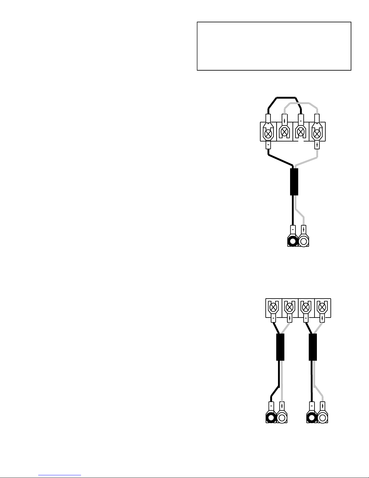
TRUE BI-WIRE CONNECTIONS
True bi-wiring is recommended for all systems using a
single stereo amplifier or two mono amplifiers. Four identical runs of equal length cable are required. (Two per
speaker).
1. Crimp and solder spade lugs to the speaker ends of the
cables being used to connect the 2Ce Signatures II.
2. Choose one of the cables as high-frequency cable. Con-
nect this cable to the two terminals on the right carefully
observing proper polarity.
3. Connect the remaining cable to the two left terminals
carefully observing proper polarity.
4. Connect both cables in proper polarity to the same set of
outputs on your amplifier. If possible, use only one
spade lug to connect both cables to each terminal on the
amplifier as shown in the amplifier connection.
With all the connection methods, bare wires
should never come into contact with the aluminum plate while the amplifier in on. Amplifier
damage could result.
Carefully verify cable pol arity at both speaker
and amplifier before using the bi-wire or vertical bi-amp connection methods.
True
Bi - Wire
INTERNAL BI-WIRE CONNECTIONS
If your domestic situation dictates the use of a single cable per speaker, you should use a multiple-conductor singlesheath cable to internally bi-wire the speakers. Some of
these cables use different types of wire for the upper and
lower ranges of the speaker and may affect the blend between the woofer and midrange drivers. They should only
be used after you audition them in your system and verify
that they do not affect the woofer to midrange blending and
that you like their sonic characteristics.
1. Crimp and solder spade lugs to the speaker ends of the
cable from the amplifier.
2. Connect one positive and one negative wire to the high-
frequency terminals on the right carefully observing
proper polarity.
3. Connect the remaining positive and negative wires to
the low-frequency terminals on the left carefully observing proper polarity.
4. Connect the wires in proper polarity to the same set of
outputs on your amplifier. If possible, use only one
spade lug to connect both positive wires and one spade
lug to connect both negative wires to the amplifier as
shown in the diagram.
Amplifier
Terminal
Internal
Bi - Wire
Amplifier
Terminal
2
Page 3
ENHANCED MONO-WIRE CONNECTION
Mono-wiring should only be used with the 2Ce Signature
II as a temporary connection method. The speakers should
be bi-wired as soon as possible.
1. Cut two sections of insulated wire about 2½ inches
long to make two jumper wires. Crimp and solder
spade lugs to all four ends of the two jumper wires.
2. Connect one end of a jumper wire under the high -
frequency negative terminal screw and one end of the
other jumper wire under the high-frequency positive
terminal screw.
3. Crimp and solder spade lugs to the speaker ends of
the cable from the amplifier.
4. Connect the negative side of the speaker cable and the
jumpper cable from the high-frequency negative
terminal screw under the low-frequency negative
terminal screw.
5. Connect the posite side of the speaker cable and the
jumper cable from the high-frequency positive
terminal screw under the low-frequency positive
terminal screw.
6. Connect the speaker cables to your amplifier. Verify
proper polarity.
The performance of the Model 2Ce Signature
is compromised by a mono-wire connection.
For optimum performance you should bi-wire
the speakers.
MONO-WIRE
VERTICAL BI - AMP CONNECTIONS
Caution: Some solid state amplifiers are not stable driving a capacitive load. Listen for high frequency oscillation
(brightness) and higher amplifier operating temperature.
We only recommend bi-amplification when every component in the system is the best available and there is no
other path to improving the system, otherwise, you are better off investing in the best single amplifier within your
budget rather than dividing your budget between two less
expensive, inferior sounding amplifiers.
Vertical Bi-amplification uses a stereo amplifier to drive
each speaker. Four identical runs of equal length speaker
cables are required (Two per speaker).
1. Connect two cables to each speaker as described in
steps 1-3 of the true bi-wire section on the previous
page.
2. Designate one stereo amplifier as the left channel am-
plifier and the other identical stereo amplifier as the
right channel amplifier.
3. Connect the preamp’s left channel output to both inputs
of the left amplifier using two sets of preamplifier outputs and two cables or one cable and a high quality single female to dual male “Y” connector. Use the same
method to connect the preamplifier's right channel output to both inputs of the right amplifier.
4. Connect the low-frequency cable from the left speaker
to one channel of the left amplifier. Connect the highfrequency cable from the left speaker to the other channel of the same amplifier. Verify proper polarity.
5. Repeat step 4 for the right speaker and the right ampli-
fier.
VERTICAL
BI - A MP
Amplifier
Left Channel
Outputs
Amplifier
Terminal
Right Channel
Outputs
3
Page 4

WE RECOMEND
A. All speaker cables in bi-wired or bi-amped systems
should be the same type and length. While certain different cables may work well together, identical cables
on both inputs insures perfect blending.
B. If your amplifier has “A” and “B” outputs, use the “A”
outputs for both cables in bi-wired systems. The two
sets of outputs may not be electrically identical.
BI-WIRING THEORY AND PRACTICE
The effects of bi-wiring are not subtle. The improvements are large enough that a bi-wire set of moderately
priced cable will usually sound better than a single run of far
more expensive cable.
All the cables in a bi-wire set must be the same. There is
often great temptation to use a wire known for good bass
response on the woofer inputs and a different wire known
for good treble response on the midrange/tweeter inputs.
This will cause the different sonic characteristics of the two
wires in the middle frequencies to interfere with the proper
blending of the woofer and midrange driver through the
600Hz crossover point. The consistency of the sound will be
severely affected as the different sounding woofer and midrange drivers conflict with each other in the frequency range
where our ears are most sensitive to sonic anomalies. The
disappointing result is a vague image, a lack of transparency
through the midrange and lower treble and loss of detail and
clarity.
Some of the benefits of bi-wiring seem to come from the
physical separation of the high current bass and low current
C. If your amplifier has multiple impedance taps, try the 4
ohm and 8 ohm taps to see which sounds better. (They
will sound different). The 2Ce Signature II is an easy
load so there is no danger of damaging your amplifier
or the speakers by using either set of taps. In bi-wired
and bi-amped systems, both cables must be connected
to the same rated taps on the amplifier.
midrange/tweeter wires. Cables that combine the wires in
one sheath do not offer the full advantages of bi-wiring.
The cables should all be the same length. This is not due
to the time that the signal takes to travel through a cable, but
rather that two different lengths of the same cable will sound
different. If the cables connecting one speaker are a different length than the cables connecting the other speaker, the
resulting difference in sound between the two speakers will
compromise the imaging and coherence of the system. If
different lengths of cable are used for the bass and midrange/
tweeter inputs of the speakers, the effects will be similar to
those experienced when using two different cables as described above.
Since short runs of speaker cable sound better than long
runs, consider placing your electronics between the speakers
rather than off to one side. If for convenience or aesthetic
considerations, the electronics must be located a considerable distance from the speakers, it is usually preferable to
place the amplifier between the speakers and use long interconnect cables and short speaker wire.
BI-AMPLIFICATION THEORY AND PRACTICE
When you vertically bi-amplify with two identical amplifiers, almost every aspect of the Model 2Ce Signature II ’s
performance is enhanced compared to bi-wiring with just
one of the amplifiers. In most cases however, bi-wiring
with a single, twice-as-expensive, better sounding amplifier
will offer greater performance improvements for the same
investment.
With the separate inputs for the midrange/tweeter and
woofer on the 2Ce Signature II’s, you may be tempted to biamplify the speakers using a powerful amplifier or an amplifier known for superb bass performance on the woofer input
and a smaller amplifier or an amplifier renowned for middle
and high frequency performance on the midrange/tweeter
input. But rather than improving the sound of your system
with the addition of a second amplifier, you will have taken
a significant step backwards in coherence, accuracy and musical realism.
The reasons for this sonic penalty are simple. One of the
strongest aspects of the Model 2Ce Signature’s performance
is the seamless transition between the drivers. Whether the
music is in a range being reproduced by the woofer, by the
midrange, or equally by both drivers, there is no audible
change to the characteristics of the instruments or voices.
But, when the midrange driver is being driven by a different
amplifier than the woofer, (and in these cases by amplifiers
not chosen for the similarity in their sounds, but rather for
the difference in their sounds), the blending between the
drivers is compromised and the sonic consistency of the
speaker is inhibited.
Even if the levels of the two amplifiers are matched for
one volume level, the amplifiers will still exhibit different
dynamic characteristics, different imaging characteristics,
different degrees of detail and instrument texture and different tonal balances. With the crossover between the woofer
and midrange occurring in a range where the ear is very sensitive to any sonic changes, these differences will create considerable sonic confusion through the important midrange.
The only way to properly bi-amplify the Model 2Ce Signature II is passively with two identical amplifiers in a vertical configuration. (one stereo amplifier per channel) An
electronic crossover cannot be used since the crossover in
the Model 2Ce Signature II is not bypassed. The result
would be two crossovers in series creating severe phase
shift. The use of two different amplifiers or an electronic
crossover will negatively affect the sound of the speakers
and reduce their overall performance level.
4
Page 5

S
ETTING-UP THE SPEAKERS
The Model 2Ce Signature II requires a break-in period of at least 100 hours at a
moderate volume level before its performance stabilizes. Higher volume levels
will not shorten this break in period.
Vandersteen speakers will produce excellent, satisfying sound placed almost
anywhere in a room. With all the possible variables in room layout, there are
no magical formulas for determining the best speaker placement in every room.
Since every room is different, we recommend that you try the speakers in every
domestically acceptable location to find where they sound the best in your particular listening environment. The following sections contain suggestions that
may be helpful in your placement experiments.
S
PEAKER PLACEMENT
The 2Ce Signature II is not magnetically
shielded and should be positioned at least 10
inches away from a direct view television set.
Problems can arise when you attempt to place a given
loudspeaker, either front radiating or dipole, into a typical
domestic environment. These problems are a function of
the physical dimensions of the room. The room’s dimensions dictate where in the room a node or anti-node will
occur. Frequency response dips and peaks caused by
nodes and anti-nodes can easily overwhelm the inherent
accuracy of a loudspeaker.
If, for example, you place a loudspeaker with excellent
frequency response characteristics in the corner of a room,
you will increase response below about 200Hz by 6dB.
This particular condition is a worst case example but similar conditions apply throughout the room to some extent.
O
DD DIMENSIONS PLACEMENT
Research on speaker placement has produced a method
for reducing the nodes and anti-nodes in many rooms by
positioning the loudspeakers on the odd dimensional intersections of the room. The odd dimensional intersections
are the intersections of the imaginary lines you would
draw if you divided the length of your room and the width
of your room by odd numbers.
As an example, we will use a rectangular room measuring 14 feet wide by 18 feet long. We’ll assume that you
want to set the speakers on one of the short walls, although this method works equally well for long wall
placement.
The first step is to take the length of the room, (18 feet
in our example) convert it from feet to inches, (18 X 12 =
216) and divide the result by odd numbers.
216 divided by 3 is 72 (all to the nearest inch)
216 divided by 5 is 43
216 divided by 7 is 31
216 divided by 9 is 24
216 divided by 11 is 20
216 divided by 13 is 17 (and so on; eventually
the lines pile on top of each other or the speaker runs into
the wall.) The results are the distances in inches that the
center of the speakers can be placed into the length of the
room, away from the wall behind them, to minimize the
nodes and anti-nodes.
Now we can graph these odd dimensions distances on a
drawing of the room. We only need to graph them for the
wall where we intend to place the speakers.
24 31 43 72
We use the same method to figure how far the centers of
the speakers should be from the side walls. We take the
width
of the room, (14 feet) convert it from feet to inches,
20
17
5
Page 6

(14 X 12 = 168) and divide the result by odd numbers.
168 divided by 3 is 56 (all to the nearest inch)
168 divided by 5 is 34
168 divided by 7 is 24
168 divided by 9 is 19
168 divided by 11 is 15
The results of these odd number divisions are the distances in inches that the center of each speaker can be placed
into the width of the room, away from the side wall, to minimize nodes and anti-nodes.
Now we can graph these odd dimensions distances on a
drawing of the room.
15
Placing the speakers on different rather than matching
width lines will require that the listening position be offset
to center it between the speakers. Often, the bass response
of the system will be slightly more linear with the speakers
placed on different width lines, (asymmetrical placement)
while the imaging will often be better with the speakers
placed on matching width lines (symmetrical placement).
34
24
34
56
56
34
24
15
By overlaying the width and length graphs, we can see
the intersection points of the lines. These points represent
where the centers of the speakers should be placed to minimize nodes and anti-nodes.
15
24
34
56
56
34
24
15
24 31 43 72
As you can see, we now have quite a few intersections to
choose from in our example room. Some of the intersections
in your room will probably be eliminated by aesthetic or
room function considerations, so you probably will not have
as many.
As you try different placements for your speakers, always
place both speakers on the same length line. For example,
both speakers would be placed on the 24 inch line. The
speakers can be placed on different width lines, for example
one on the 34 Inch line and the other on the 56 inch line.
Listening Position
34
Symmetrical Placem ent
34
Listening Position
56
31
Asymmetrical Placement
After listening to the speakers centered on the charted
intersections, you should listen with the speakers a couple
of inches away from the intersection points in each direction. In some cases, the speakers will sound better
slightly off the intersections due to the particular characteristics of your room or a slight error in your original
room measurements. Both speakers should be moved the
same amount forward or backward when fine-tuning
placement.
Several factors influence how speakers interface with a
room other than the room’s basic dimensions so it is possible that none of the placement options on the wall you
initially place the speakers on will sound quite right. The
sound may have too much or too little bass or be too forward or too withdrawn. If you are unable to achieve satisfactory sound with the speakers placed on one wall, try
placing the speakers on another wall of the room. Even in
a rectangular room, the speakers will interface differently
with the room depending upon which of the four walls
they are placed. In some rooms the speakers will sound
6
Page 7

best placed on a short wall while in other rooms the speakers
will work better on a long wall.
THIRD DIMENSIONS PLACEMENT
A placement method that provides some unique effects is
to place each speaker on the thirds of the room measurements and the listening position on the third of the length.
The speakers are placed one third the length of the room
from the wall behind them and one third the width of the
room from the walls along side them. The listening position
is then placed one third the length of the room from the wall
behind it.
56
Listening
Position
56
72
72
In our 14 by 18 foot example room, the thirds are 72
inches in the long dimension and 56 inches in the short dimension. The intersections of these measurements are used
for third dimensions placement. In addition, the listening
position is placed 72 inches from the rear wall of the room.
Both speakers should be tried up to two inches ahead and
behind the intersections to determine if this improves the
sound. Both speakers should be moved the same amount
forward or backward.
Third dimensions placement reduces the interaction of
the speakers with the room to an absolute minimum, but can
create aesthetic or room function problems due to the speakers and listening position being so far out in the room. (The
lower the odd number used to divide the room dimensions
the lower the interaction between the speakers and the
The same distance from the rear and side walls. The measurement from the center of the loudspeaker to the two walls
should differ by at least two inches. If any of the odd dimension intersections are within two inches of the same
distance from both the side and rear wall, you should not
S
PEAKER
The degree of toe-in can affect the imaging and re-
T
OE-IN
sponse characteristics of the speakers. In most rooms, the
speakers will work well facing straight ahead or with a
slightly toed-in. Speakers that are placed close to the side
walls or in rooms with very reflective side walls may require additional toe-in to avoid a confused image and/or a
forward midrange and treble.
If the speakers need an excessive amount of toe-in to
image properly or achieve good center fill, there may be a
problem with the set-up or connection of the speakers or
some part of the system may not be functioning as intended. To determine why the speakers require excessive
toe-in, check all your speaker wire connections for correct
phase and verify that the electrical components in the system are connected and functioning properly.
A
COUSTIC TREATMENTS
If the speakers are close to the side walls and you hear a
brightness in the midrange/treble or a problem with the
imaging that toeing-in the speakers does not help, some
sound absorbent material should be mounted on the side
walls to control reflections.
to determine where the sound absorbent material should
be placed, imagine that the walls are mirrors and mount the
material on the walls where you would see the reflections
of the speakers when you are sitting in your normal listening position. Before you actually mount anything on the
side walls, experiment with folded natural-fiber blankets to
verify that you will get the results you desire.
Speaker
A
COUSTICAL CENTER
The Model 2Ce Signature II acoustical center is the
physical center of the loudspeaker. In a perfectly rectangular room with absolutely rigid walls and no doors or windows,
the acoustical center of the loudspeaker
would be placed exactly at the point where
the two dimensions intersect to realize the
full benefits of odd dimensions or third di
mensions placement. In a real room, the ac
tual best placement may vary from the in tersection by as much as two inches or so.
Fine-tuning the placement by moving the
speakers a couple of inches off
the odd dimensions intersections takes
these real world conditions into account.
You should not use any placements that
Listening
Speaker
Position
If your listening position is close to the wall behind
you, mount some sound absorbent material, such as a
hanging tapestry, directly behind your head. As with the
material for the side walls, experiment with a folded natural-fiber blanket to verify the results before you acquire or
mount the material.
Bass problems that cannot be corrected with placement
adjustments may be helped by the addition of bass traps or
other bass control devices. Follow the instructions of the
bass control devices as to their proper set-up and placement to correct the problems you are experiencing.
7
Page 8

LISTENING HEIGHT
The sound from a properly aligned loudspeaker reaches
the listener with the audible frequencies correct in both time
and phase. This lack of phase and time distortion contributes
to a more accurate sound, but also makes listening a the
proper height more important than with a nonaligned design.
A characteristic of all properly aligned loudspeakers is that
they are perfectly aligned at only one listening height. The
further away your ears are from this perfect alignment
height, the less accurate the speaker will be in the time and
frequency domains.
The Model 2Ce Signature II is aligned for a 33 inch listening height when placed on a 3 inch high base. It has a
vertical listening window extending about 3 inches above
and below the alignment height where the sound of the
speaker will still be quite good. Outside of the vertical listening window, the sound and performance of the speaker
will be compromised.
If your ear height is above 33 inches at your normal listening position, the speakers can be leaned back according
to the following instructions to raise the optimu m listening
window up to your ear height.
1. Measure the distance from the listening position to the
speakers and the height of your ears when you are
seated at the listening position. (Ear height is roughly
equal to the height of the tip of your nose).
2. Find the values closest to your actual measurements on
the chart at the right.
3. Follow the horizontal line across from your distance and
the vertical line up from your ear height to the point
where they intersect. The graph lines numbered from 0
1/2
to 3
indicate how many inches the top of the speaker
should be behind the bottom of the speaker to center the
six inch listening window at your listening height and
distance.
4. Adjust the length of the base’s front and rear spikes to
lean the speakers backward the proper amount.
5. As an example of how to get the proper amount of lean:
a. Tie a nut to a piece of thread about four feet long.
b. Hang the thread and nut from the back of the speaker
and measure the distance the nut is away from the
bottom of the speaker as shown in the diagram. This
measurement is the amount of speaker lean. (For clar ity, the lean in the diagram has been exaggerated and
the base is not shown).
Distance From Speakers In Feet
0
18
17
16
15
14
13
12
11
10
9
8
33 35 37 39 41 43 45 47
Average Ear Height In Inches
1 1/2
2 1/2 1
2 1/2
3
3 1/2
THE CONTOUR
Two contour controls are located on the aluminum dress
C
ONTROLS
plate at the rear of the Model 2Ce Signature. The upper control adjusts the tweeter level and the lower control adjusts
the midrange level.
The contour controls are used to compensate for a bright
or dull room that could not be corrected with speaker placement, acoustical treatments or other passive means. The controls are limited in their effects and even at maximum rotation they will not take the response of the speaker out of a
plus or minus 3dB envelope. Changing the contour
controls will not affect the detail, imaging or phase performance of the speakers due to their unique incorporation
into the crossover circuitry.
When using the controls, we recommend that you start
with small adjustments and only change the midrange controls or the tweeter controls before listening for the effects
of the change. By changing only one pair of controls, you
will be able to determine the effects that each pair of controls have upon the sound of the speakers in your room.
8
Page 9

HELPFUL SET-UP HINTS
A. To try the speakers on different walls, set your equip-
ment in the middle of the room so the speaker cables
can reach each position.
B. When you change the placement of the speakers, listen
to several different pieces of music before judging the
results.
C. If you set the speakers on a wood floor, place a coin
under each stand spike or use 3/8-16 thread carriage
bolts in place of the spikes to prevent damage to the
floor. Carriage bolts have rounded heads that will not
put holes in the floor.
D. Keep the spikes or carriage bolts on the bottom of the
stands as short as possible while still accomplishing the
proper vertical angle for your listening height and distance.
A
SSOCIATED EQUIPMENT
AMPLIFIER REQUIREMENTS
The Model 2Ce Signature II is designed for use with
amplifiers rated at 40 to 160 watts per channel into 8 ohms.
Amplifiers in this power range will provide ample power
for realistic listening levels in most situations. Amplifiers
with less than 40 watts may not be able to drive the Model
2Ce Signature to realistic listening levels without stress,
while amplifiers with more than 160 watts must be used
with caution due to the increased potential for speaker damage if they are misused or an accident occurs.
The Model 2Ce Signature II’s are very revealing speakers and are easily capable of showing subtle sonic differences between amplifiers. They will perform well with a
COMPONENTS
E. When you have discovered the optimum speaker posi tioning in your room, mark it with tape so you can move
the speakers to vacuum without loosing your placement
reference.
F. If the bass is ill-defined in your room regardless of
where you place the speakers, check your windows for
loose panes of glass. Loose glass will vibrate and can
seriously impair the low frequency detail of the system.
G. Keep notes on the sound different placements you try. It
is easy to get mixed-up and forget which placement
sounded the best.
H. Don’t over-analyze sound of each placement. When the
sound is right, it will be obvious.
transistor, or hybrid amplifier, allowing each design to realize its full potential. The amplifier can be a quality receiver, integrated amplifier or separate amplifier. The stable impedance of the Model 2Ce Signature reduces load
induced amplifier problems, expanding the possible amplifier choices.
The stability of the amplifier to be used should be considered, as it will affect the current capability and therefore,
the dynamics and realism of the music. A stable transistor
amplifier will be able to deliver twice the wattage into 4
ohm load as is does into an 8 ohm load. Amplifiers with
this ability should perform well with the Model 2Ce Signature.
To maximize the performance of your system, you
should properly set-up your components according to the
manufacture’s instructions. Each component should be
placed on a piece of furniture or in a stand that is stable and
not prone to vibration or rocking. An isolation base or isolation feet may improve the sound of some electronics.
Allow sufficient air space around the electronics for
needed air circulation. Excessive heat can both shorten the
CABLES
Our evaluations and tests have convinced us the interconnect and speaker cables should be considered an integral part of the music system. Each brand and model of
cable has its own sonic characteristic and contributes to the
overall presentation of the music as much as any active
component. The Model 2Ce Signature easily passes the
amount of information required to hear these differences
between cables.
The testing also confirmed the importance of keeping
speaker cables as short as possible. In repeated trials, short
runs of moderate to inexpensive speaker cable consistently
out performed long runs of the same cable as well as much
the life of electrical components and impair their performance.
Preamplifiers and CD players should be left on all the
time. Amplifiers should be turned off when the system is
not being used. Once broken in, modern amplifiers sound
good after only 20 minutes of warm-up. Leaving the amplifier on all of the time exposes the speakers to possible damage from power line anomalies or electrical component
failure while the system is unattended
more expensive cable. If your speakers must be placed a
long distance from your electronics, we recommend that
the amplifier be placed between the speakers and long interconnect cables be used between the amplifier and power
amplifier so that short speaker cables can still be used. Currently, long interconnect cables seem to compromise the
sound of a stereo system less than long speaker cables.
When you evaluate different interconnect or speaker
cables, remember that the dielectric in most quality cables
takes many hours to fully form. These cables will not reach
their full potential until they have been used for several
weeks.
9
Page 10

S
PEAKER CARE
MAINTENANCE
The appearance and performance of the Model 2Ce Signature II can be enhanced by observing a few precautions and
performing some simple maintenance.
The input jacks on the Model 2Ce Signature II and the
banana plugs should be cleaned periodically with alcohol or a
solution made specifically for cleaning electrical contacts. A
cotton swab with a small amount of cleaning solution on it
can be used to clean inside the input jacks. Other connection
points in the system should be cleaned as recommended by
the equipment’s manufacturer.
SERVICE
In the unlikely event that one of your speakers should require service, please follow these procedures.
1. Verify that the problem is with the speaker by switching
the left and right speakers. If the problem follows the
speaker, it is in the speaker. If the problem does not follow the speaker, it is in the system before the speaker.
2. Connect the tweeter/midrange input and bass inputs separately to determine which section of the speaker has the
problem
The grille cloth on the Model 2Ce Signature II can be
vacuumed using a brush attachment that will not snag the
cloth. The top should be treated as a piece of fine furniture. The wood veneers are oiled at the factory and can
be maintained with a light application of Pledge or a
similar product.
Care must be taken that objects that could mar the
finish are not placed on top of the speaker. The speaker
should not be exposed to excessive direct sunlight which
can damage the fit and finish of the veneer.
3. Contact Vandersteen Audio. Describe the problem
and the steps you have taken to isolate the problem
to the speaker. A return authorization form will be
sent to you.
4. When you receive the return authorization form, re
turn the damaged or defective loudspeaker to
Vandersteen Audio packed in its original box. Pack
the filled-out return authorization form in the box
with the speaker.
PACKING INSTRUCTIONS
To prevent physical or cosmetic damage, the Model 2Ce
Signature II should always be properly packed in its original
box prior to transportation or shipment. Please follow these
instructions when packing the Model 2Ce Signature II.
1. Turn the speaker upside-down on a carpeted surface and
remove the base.
2. Pull the plastic bag down over the speaker.
3. Slide the inner liner over the speaker.
4. Fit one of the end trays into the end of the inner liner
with the open area of the end tray facing away from
the speaker.
5. Holding the flaps out, slide the outer box over the inner
liner all the way to the floor.
6. Carefully turn the box right-side up.
7. Close the plastic bag and place the remaining end tray
into the inner liner as was done in step 4.
8. Close the flaps on the outer box and seal with strong
tape.
Speakers must be spaced away from the
ends of the outer box. If both ends trays are
not available, space the speaker away from
the ends of the box with cardboard or a
similar protective material.
End Tray
Plastic Bag
Speaker
Inner Liner
Outer Box
End Tray
The open areas of th e end trays must
always face away from the speaker.
The flat surfaces of the end trays
must be against the spe aker.
10
Page 11

F
OR FUTURE REFERENCE
Speaker Serial Numbers:
Purchase Date:
5 year warranty applied for: and received:
Dealer Name:
Dealer Address:
Dealer Phone:
Dealer Contact:
S
PECIFICATIONS
Acoustic
Coupler:
Woofer: 8” with die-cast basket and curvilinear polycone.
Midrange: 4.5” with die-cast basket, linear surond and curvilin-
Woofer: 1” critically damped metal alloy dome with ferro-
Crossover: 600Hz and 5kHz.
10” with critically damped long-fiber cone and
heavy duty 1.5”, four-layer voice coil wit h ventilated aluminum former.
Range of operation: 28Hz to 35Hz.
1.5 inch, two-layer voice coil with ventilated aluminum former. 40oz foucused-gap magnet structure.
Range of operation: 35Hz to 600 Hz.
ear polycone. Ferrofluid voice coil cooling.
Range of operation: 600Hz to 5kHz.
fluid voice coil c ooling.
Range of operation: 5kHz to 30kHz.
First-order, 6dB per octave. Allows bi-wiring with a
single amplifier or vertical bi-amplification with
two identical amplifiers.
Impedance: 7 ohms nominal. 4 ohms minimum.
Efficiency:
Response:
Recommended
Amplification:
Video
Applications:
Physical:
Specifications and design subject to change without
notice due to continuing research and development.
86db with 2.83 volts of pink noise input
at 1 meter on axis.
28Hz to 29kHz 3db.
32Hz to 21Hz 1.5db
40 to 160 watts per channel into 8 ohms.
Main or surround speakers.
The Model 2Ce Signature is not magnetically shielded and should be po sitioned at least 10” away from the direct
39.75” high x 16” wide x 10.25” deep.
60 pounds net, 71 pounds gross each.
VANDERSTEEN AUDIO
116 W
H
ANFORD
EST FOURTH
, CA 93230
ST.
(559) 582-0324
www.vandersteen.com
Model 2Ce Signature II Operation Manual. 11
11
Page 12

L
IMITED ONE YEAR WARRANTY
VANDERSTEEN AUDIO loudspeakers are warranted to the original purchaser to be free from defects in materials or
workmanship, SUBJECT TO THE FOLLOWING CONDITIONS, for one (1) year from the date of purchase from an
authorized VANDERSTEEN AUDIO dealer.
THIS WARRANTY IS SUBJECT TO THE FOLLOWING CONDITIONS AND LIMITATIONS:
This warranty is void and inapplicable if the loudspeaker have:
A. Not been used in accordance with the instructions contained in the operation manual.
B. Been subject to misuse or abuse; examples of which would be burned driver voice coils or burned crossover compo-
nents.
C. Been modified, repaired, or tampered with by anyone not specifically authorized to do so by Vandersteen Audio.
D. Been subject to inputs in excess of the maximum rating, or inputs from an unstable or clipped amplifier.
E. Suffered physical damage to the structure or components due to accident, neglect, or transportation.
IF A VANDERSTEEN AUDIO LOUDSPEAKER FAILS TO MEET THE ABOVE WARRANTY AND THE ABOVE
CONDITIONS HA VE B EE N MET, T HE N T HE C US T OM ER’ S S OLE REMEDY SHALL BE TO RETUR N T HE
PRODUCT TO VANDERSTEEN AUDIO WHERE THE DEFECT WILL BE REPAIRED WITHOUT CHARGE FOR
PARTS OR LABOR. THIS WARRANTY APPLIES ONLY TO PRODUCTS RETURNED TO VANDERSTEEN AUDIO IN HANFORD, CA USA.
(Returning the product to Vandersteen Audio from some countries other than the United States may involve considerable
time and expense. The customer is responsible for all fees and duties and for providing instructions and all the paperwork
required to return the product after it is serviced.)
The speaker must be packed in the original packing and returned to VANDERSTEEN AUDIO via insured freigh t by the
customer at his or her own expense. A returned product must be accompanied by a Return Authorization Form, (available
from VANDERSTEEN AUDIO upon request) which includes a written description of the defect and return shipping
information.
ANY IMPLIED WARRANTIES RELATING TO THE ABOVE PRODUCT SHALL BE LIMITED TO THE DURATION OF THE ABOVE WARRANTY. THIS WARRANTY DOES NOT EXTEND TO ANY INCIDENTAL OR CONSEQUENTIAL COSTS OR DAMAGES TO PURCHASER.
Some states do not allow limitations on how long an implied warranty lasts, or an exclusion of incidental or consequential damages so the above limitations or exclusions may not apply. This warranty gives you specific legal rights, you may
also have other rights in your state.
VANDERSTEEN AUDIO reserves the right to modify the design of any product without any obligation to previous purchasers and/or to change the prices or specifications without notice or obligation to anyone.
I have been doing volunteer work for severa l years with elderly people with severe hearing
losses, and I ha ve seen the frustration and anger that are brought on by these loses. We
now know that many of these people developed their hearing problems because of exposure to high noise levels when younger.
Many home stereo systems, as well as audio/video, personal, a nd automobile sound s ystems are capable of volume levels potentially damaging to your hearing. Please use common sense, and l isten to your music and movies at safe levels now so you will still have
the ability to hear and enjoy them in the future.
Model 2Ce Signature II Operation Manual © Copyright 2009 Vandersteen Audio, Inc.
A P
ERSONAL NOTE
Richard Vandersteen
12
 Loading...