

Page 1

$5.00
VANDERSTEEN QUATRO
SIGNATURE LOUDSPEAKER| OPERATIONS MANUAL
Thank you for choosing the Vandersteen Quatro Signature Loudspeaker System. Be careful handling the Quatro while unpacking or moving them. The top sixteen inches of the front grille should
not be touched in any way. The tweeter and midrange are immediately behind the fabric and can
be easily damaged by probing fingers. These drivers are very expensive and carefully matched.
Use care. For a complete understanding of the Quatro’s innovative technology and unique features
we recommend that you review this entire manual before connecting or using your new speakers.
Vandersteen Audio
The Quatro combines the superior openness and realism
of the legendary Vandersteen boxless design with the powerful, extended bass of an amplified subwoofer in a compact
and elegant loudspeaker. Unique features optimize the
Quatro for a wide variety of placements, environments, and
system configurations. It is available in several wood types
to complement almost any décor.
The Quatro is factory upgradeable. Future advances in
technology and/or materials may be incorporated into
your speakers. Your Quatros will always be totally upgradeable to the latest version.
On the rear input plates are room compensation controls that a qualified technician uses to match the low frequencies to the listening room and level and contour controls that allow you to tailor your Quatros to your own
personal taste.
The Vandersteen Quatro is designed and built in the
United States of America.
Unless the high-pass crossover is built into the electronics, (See page 3.) the Quatro
system requires a M5-HP crossover between the preamplifier and main power amplifier that is matched to the input impedance of the power amplifier. Using the speakers without a properly configured M5-HP in place will severely damage the midbass
drivers. The drivers in your Quatro are critically paired to within one tenth of a dB.
If one driver is damaged, the pair must be replaced. Physical damage (probing fingers) or damage due to a missing or improperly configured M5-HP crossover will require non-warranty replacement of two very expensive drivers. (Minimum $180.00
per pair for the tweeters alone.)
CONTENTS
SETTING-UP
The M5-HP Crossover
High-Pass Electronics
The Speaker Cables
Bi-Wire Connections
Internal Bi-Wire Connections
Speaker Placement
Installing The Cones
1 Quatro Operation Manual
Listening Height
2
2
Plugging-In The SW Amp
3
LF Room Optimization
4
Controls
5
Amplifier Requirements
6
MAINTENANCE
7
Cleaning
10
Service
SW Amplifier Replacement
10
Troubleshooting
11
Common Questions
11
Support
12
13
PACKING INFORMATION
WARRANTY
13
13
13
13
14
14
14
15
16
Page 2
SETTING-UP THE QUATROS
Unless the high-pass crossover is built into the electronics, (see page 3) the M5-HP
crossover is required in all systems. Using the speakers without a properly configured M5-HP crossover in place will cause severe and costly non-warranty damage to
the midbass drivers.
True balanced amplifiers will have the same impedance value on the positive and
negative legs of the inputs. An amplifier with different impedance values on the positive and negative legs of the inputs is not truly balanced and is not compatible with
the balanced version of the M5-HP crossover.
THE M5-HP CROSSOVER
The Quatro uses a unique crossover and subwoofer
amplification configuration to provide the true benefits of
bi-amplification and reduce the current demands on the
main amplifier. By inserting a passive high-pass crossover between the preamplifier and the main
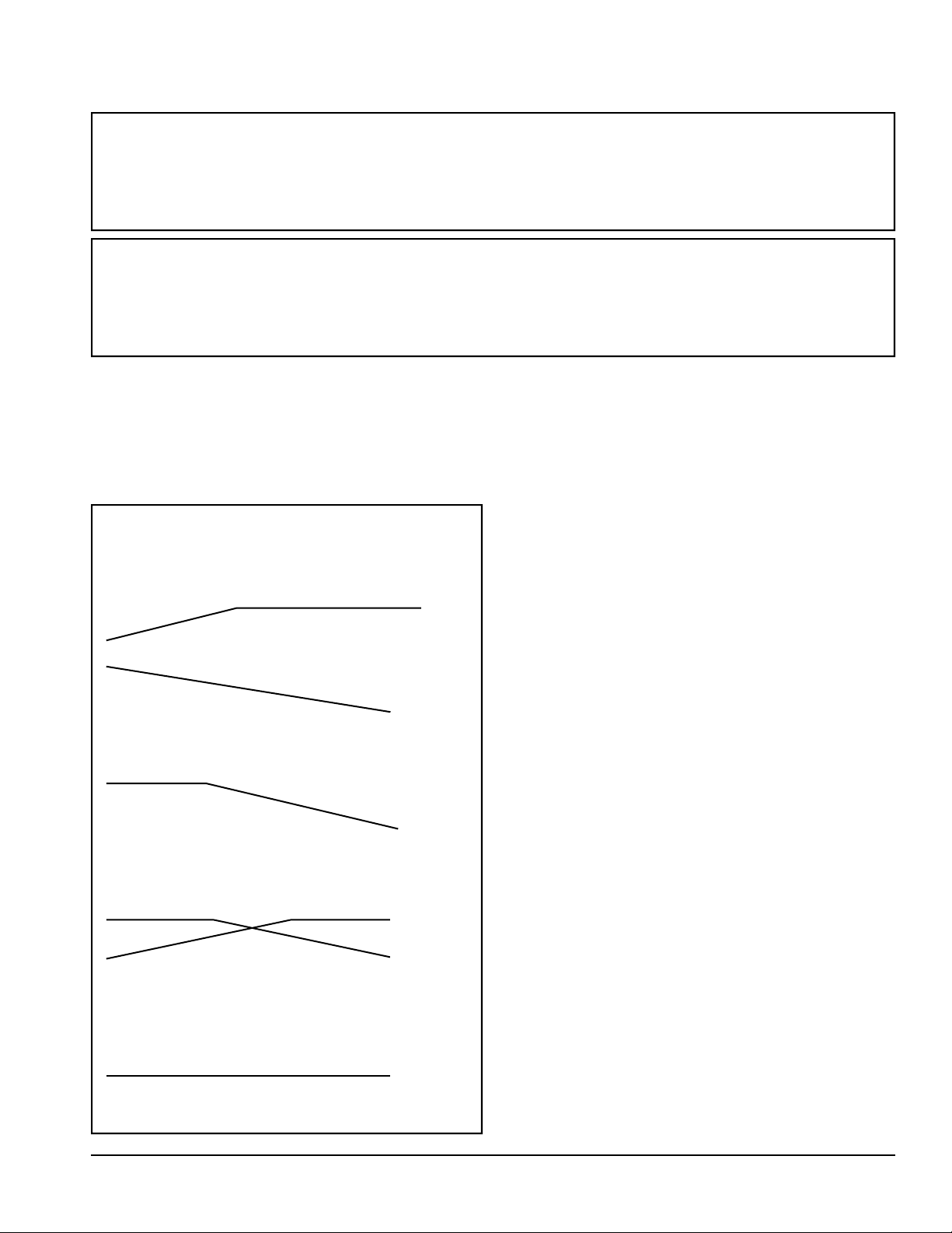
These examples show the interaction between the external crossover, the main amplifier and the Quatro subwoofer section.
20 60 100 140 180 220 260 HZ
Response of the main amplifier and
midbass driver with the low-frequency
roll-off induced by the external crossover.
Output of the Quatro amplifier. The contour is the opposite of the low frequency
roll-off induced by the crossover.
Response of the Quatro’s subwoofer.
The contour in its amplifier boosts the
frequencies below the crossover point
back to flat and rolls-off the subwoofer
above the crossover point.
Midbass
Driver
Quatro
Superimpose the response of the Quatro’s
subwoofer over the response of the midbass driver and the crossover point is
evident.
Subwoofer
Midbass
Subwoofer
Combined
Response
amplifier then connecting the Quatros like conventional biwired speakers, the main amplifier remains in the signal
path to the subwoofer, but its current demands are reduced.
This insures sonic continuity as the main amplifier’s characteristics that are evident through the upper frequencies are
maintained to the deepest bass, but with the power and control of the Quatro’s internal 300 watt amplifier.
The M5-HP is the high pass crossover for the mid-bass
driver and must be installed in the system between the preamplifier and power amplifier before the Quatros are used.
(The only exception is in systems with a high-pass amplifier
as noted below.) Properly configured to match the input
impedance of the amplifier, the M5-HP will roll off the low
frequencies going to the amplifier so that they are
-3db at 100Hz referenced to 1kHz. To compensate for the
low-frequency roll-off induced by the crossover, the response of the Quatro’s amplifier is contoured to restore the
low frequencies to the proper level as shown in the illustrations to the left. The M5-HP is a totally mono design, two
are required for a stereo pair of Quatros. M5-HPs are available in both balanced and single ended configurations to
match any system.
CONFIGURING THE M5-HP CROSSOVER
Before you use the M5-HPs, each unit’s internal set of
dip switches must be set to match the input impedance of
your main amplifier. Information on your amplifier’s input
impedance should be in its manual or available from its
manufacturer. If you do not have accurate information
on your amplifier’s input impedance, do not use your
Quatro speakers until you get the information or have a
competent technician determine the input impedance by
the method described on the next page. With balanced
amplifiers, the M5-HP crossover must be set to match the
sum of the positive and negative legs of the input. (The individual legs must each be exactly one half the impedance.) If
the individual legs do not both have the same
VANDERSTEEN AUDIO 2
Page 3
impedance, the amplifier must be used in single-ended
mode or with a complex, custom crossover the amplifier’s
manufacturer may be able to provide.
To set the M5-HPs in either a balanced or single ended
system, please follow these procedures.
1. Locate the value closest to the input impedance of
your amplifier in the chart located on the top cover
of the M5-HP. If you amplifier’s input impedance
is between values, use the lower value. Note which
switches to turn on to match the input impedance
value.
2. Remove the cover from an M5-HP and locate the
internal set of dip switches.
3. Turn on the switches listed for the value you found.
The numbered side is “ON”. A switch is on when it
is depressed on the side of the numbers.
4. Repeat the procedure for the second M5-HP.
Reinstall the covers.
If you are unable to find the amplifier’s input impedance or if you are not completely sure you have the correct input impedance, you should have a competent technician at your dealer determine the proper setting for the
M5-HPs by the following method.
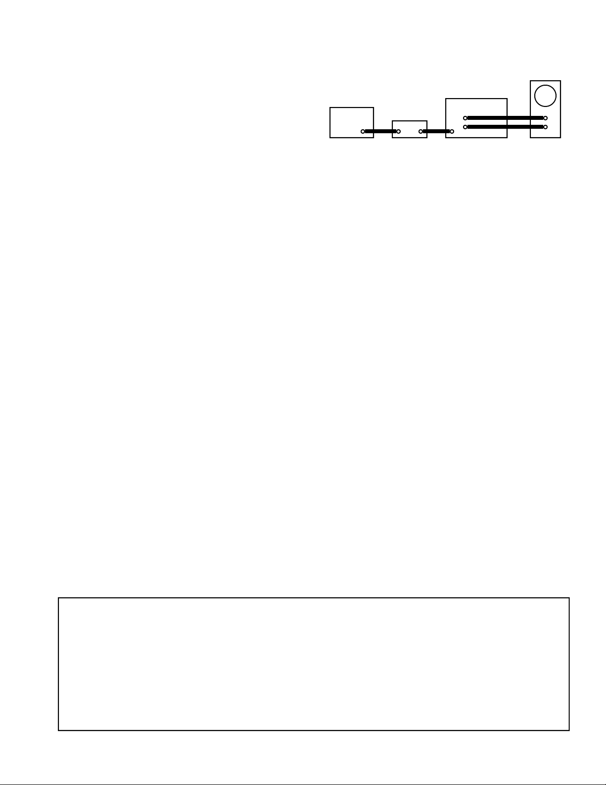
1. Connect a signal generator to the input of an M5-HP
crossover, the output of the M5-HP to the input of
your main amplifier and the output of the amplifier to an
oscilloscope as shown in the diagram below.
Signal
Generator
M5-HP
OSCILLOSCOPE
AMPLIFIER
2. Set the M5-HP’s internal dip switches for 50k imped-
ance value as noted on the chart. If the -3db down
point is above 100Hz, try a lower setting. If the -3db
down point is below 100Hz, try a higher setting. When
the -3db down point is at 100Hz, the M5-HP is set to
match your amplifier. (If the oscilloscope is not cali brated in db, find the setting where the voltage at
100Hz is .707 of the voltage at 1kHz.) This setting is
the input impedance of your amplifier. It is a good idea
to write it down for future reference.
3. Set the second M5-HP to the same setting.
The M5-HP contains a battery that continuously biases
some of its components. The battery is mounted on the
PC board and has a life expectancy of 7+ years. Please do
not attempt to measure the output of the battery as the
measurement process will drain the battery more than several months of normal use. Written on each battery is the
year that it should be replaced to insure continuous optimum performance
.
INSERTING THE M5-HP INTO THE SYSTEM
1. Connect the outputs from the properly configured
M5-HPs to the inputs of the main amplifier.
2. With a high-quality cable, connect the left channel
preamplifier output to the input of the M5-HP that is
connected to the left channel of the main amplifier.
3. With a high-quality cable, connect the right channel
preamplifier output to the input of the M5-HP that is
connected to the right channel of the main amplifier.
4. In multi-channel systems, insert the M5-HP between
the processor L&R outputs and the amplifier inputs.
HIGH-PASS PREAMPLIFIERS, AMPLIFIERS AND MULTI-CHANNEL PROCESSORS
Some preamplifiers, power amplifiers, integrated amplifiers and multi-channel processors can be configured
by the user or the manufacturer to provide the lowfrequency roll-off required by the Quatros. Incorporating the high-pass crossover into the system electronics
eliminates the need for M5-HP crossovers. The highpass section of the applicable unit must be configured to
these specifications:
Frequency Response: -3db at 100Hz
6db per octave (First order)
As you set up your Quatros, you will be prompted several times to evaluate some aspects of their
performance with reference quality music recordings. We find that natural instrument jazz recordings generally offer the most realistic and accurate sonic reproductions. They are usually of a
small group yet cover a wide frequency range. Most are straight through recordings with a minimum of processing or acoustical manipulation. If you are not really familiar with these types of recordings, try Ray Brown Solar Energy. Once you have established your reference recordings, you
can maintain consistency by using these recordings to evaluate all component, wire and placement
changes. Without reference recordings, it is easy to fall into the trap of trying to retune the system
for every different recording.
3 Quatro Operation Manual
Page 4

CONNECTING THE SPEAKER CABLES
SELECTING SPEAKER CABLES
Research has demonstrated that the speaker cables
must be considered an integral part of the music system.
Each brand and model of cable has its own sonic characteristics and contributes to the overall presentation of the
music as much as any active component. The Quatro
easily passes the amount of information required to hear
these differences between cables.
There is no one best cable to use with the Quatros. To
assure that they were sonically neutral, the Quatros were
developed using a direct-coupled laborator y amplifier
connection loaded by precision resistors to simulate cable resistance. With neutral speakers, the factors that
determine the best cables for your system are your personal taste, the characteristics of your listening room,
and the associated equipment. The only person familiar
enough with your taste and room characteristics to assist
you in selecting cables is someone from your local dealer
who has visited your room and sat through listening sessions with you. No one else can adequately evaluate two
of the three factors (taste and room).
If you wait to select the cables until the other components in the system are set, you can fine-tune the system
with your cable choice. As you evaluate different cables
in your system, remember that the dielectric in most
quality cables takes several hours to fully form. These
cables may not reach their full potential or exhibit their
true sonic characteristics until they have been in the system for a week or more.
It is very important to keep the speaker cables as short
as possible. In repeated trials, short runs of inexpensive
to moderately priced cable consistently outperformed
long runs of the same cable as well as much more expensive cables. If you must place your speakers a long distance from your electronics, you should consider positioning the amplifier between the speakers and using
long interconnect cables with short speaker cables. With
comparable lengths and quality, long interconnect cables
seem to compr omise the sound of a system less than long
speaker cables. An additional advantage is that a given
length of interconnect cable will usually cost less than
the same length of bi-wired speaker cable. An amplifier
placed between the speakers can easily be concealed by a
plant or placed in a decorative piece of furniture.
BI-WIRING
The Quatros are optimized for true bi-wiring using two
separate speaker cables to connect each speaker to the
amplifier. The speaker’s internal crossover presents different electrical characteristics to each cable so that one
cable carries the signal going to the woofers while the
other cable carries the signal going to the midrange and
tweeter. The improvements offered by bi-wiring versus a
conventional single run of cable are substantial. Often, a
bi-wire set of moderately priced cables will sound better
than a single run of far more expensive cables.
All the speaker cables in a bi-wire set should be the
same type. While it is tempting to use a cable known for
good bass response on the low frequencies and a different
cable known for good treble response on the midrange and
tweeter, the differing sonic characteristics of the two cables
can affect the blending between the midbass and midrange
drivers and compromise imaging, transparency, and detail.
Different cables should only be used after you audition
them in your system and verify that they do not affect the
midbass to midrange blending and that you like their sonic
characteristics.
Our research revealed that much of bi-wiring’s benefit
comes from the physical separation of the low frequency
cable from the midrange/tweeter cable. Internal bi-wire
cables that combine all the wires together in one sheath do
not offer all the advantages of true bi-wiring. These multiple conductor cables are the only recommended method of
mono-wiring the speakers, but should not be considered the
equivalent of dual cable bi-wiring.
BI-AMPLIFICATION
Note: Because of the powered subwoofer section of the
Quatro and the use of a high pass filter this system is biamped. We do not recommend what would then be tri amping for the following reasons:
1. The major sonic improvement achieved by tri-amping a
speaker is the removal of the bass current demand from the
main amplifier, which has already been accomplished by
the powered subwoofer and high pass filter.
2. In all scenarios a set of mono amplifiers of equivalent
value will achieve higher performance than tri-amping with
stereo amplifiers half the cost.
3. Many solid state amplifiers are unstable into a load with
no D.C. return path, which could cause the channel driving
the mid-tweeter to ring. Note: Tube amplifiers can be used
because they do not have stability problems in this scenario.
4. Many of you would like to use one type of amplifier for
the mid-bass and another for the mid-tweeter. We do not
recommend this because the Quatro’s crossover is at
600Hz, a frequency where the ear is extremely sensitive,
exactly where you do not want two different sounds mixing. The result may be better bass and/or highs but coherency will be compromised.
VANDERSTEEN AUDIO 4
Page 5
Bare wires or connectors should never come into contact with the aluminum dress
plate while the amplifier is on. Amplifier damage could result.
The input screws should be snug, but should not be over tightened.
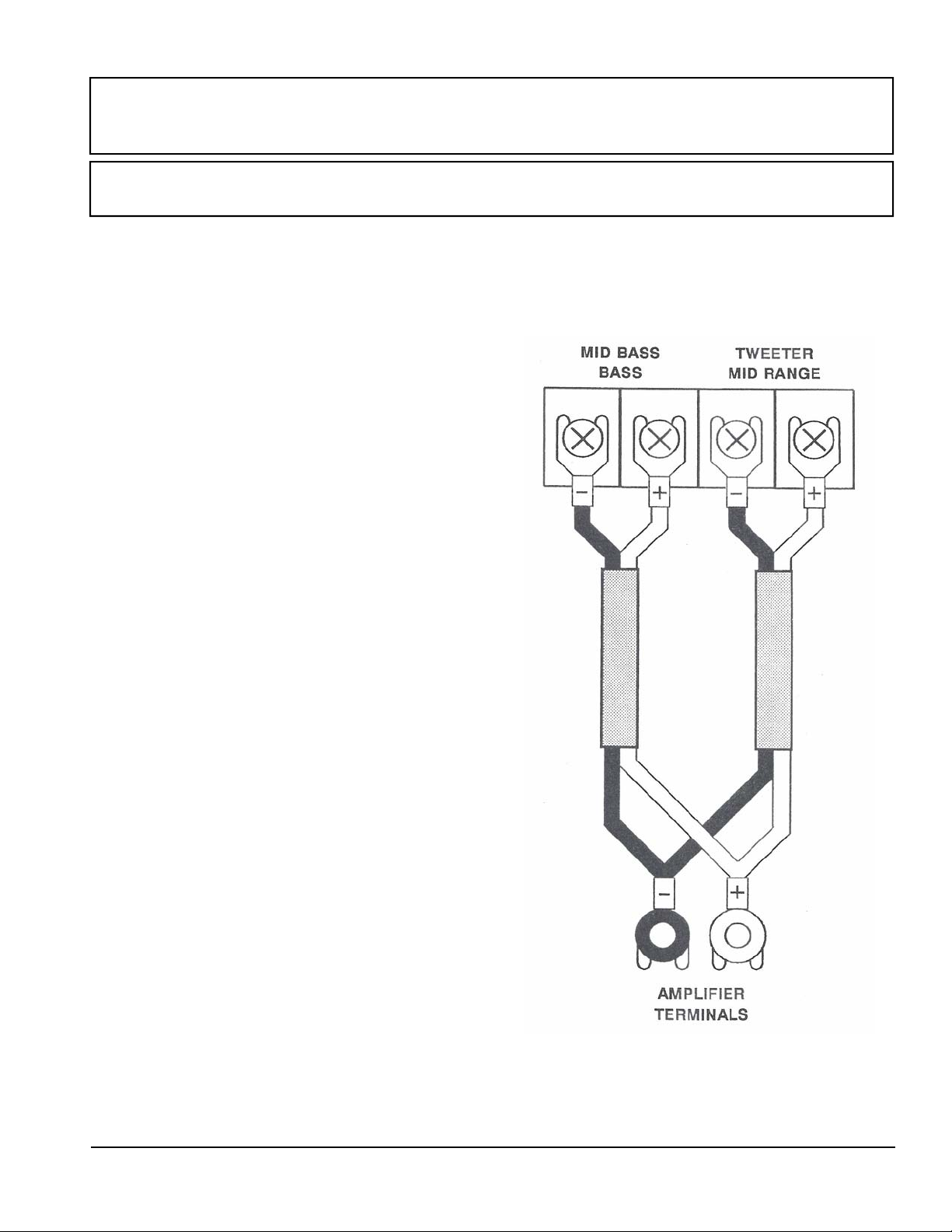
TRUE BI-WIRE CONNECTIONS
True bi-wiring is recommended for all systems using a
single stereo amplifier or two mono amplifiers. Four identical
runs of equal length speaker cables are required. (Two per
speaker.)
Please review the information on page 4 regarding cable
selection and connection techniques before you co nnect your
speakers.
1. Crimp and solder spade lugs to the speaker ends of
the cables being used to connect the Quatros.
2. Choose one of the cables as the tweeter/midrange cable.
Connect this cable to the two terminals on the right,
carefully observing proper polarity.
3. Connect the remaining cable to the two left terminals,
carefully observing proper polarity.
4. Connect both cables in proper polarity to the same set
of outputs on your amplifier. If possible, use a single
spade lug to connect both positive wires and a sing le
spade lug to connect both negative wires to the amplifier
as shown in the diagram to the right.
WE RECOMMEND TRUE BI-WIRING
a. All four speaker cables should be the same type and
length. While certain different cable types may work
well together, using identical cables on both inputs
insures perfect blending.
b. Use high quality cables and spade lugs. Crimp and solder
the spade lugs to the cables.
c. If your amplifier has “A” and “B” outputs, use the “A”
outputs for both cables. The two sets of outputs may not
be electrically identical.
d. If your amplifier has multiple impedance taps, try the 4
ohm taps and 8 ohm taps to see which sound better.
(They will sound different.) The Quatro is an easy
load and always stays between 4 and 8 ohms so there is
no danger of damaging your amplifier or the speakers
by using either set of taps. Both cables must be con nected to the same rated taps on the amplifie r.
5 Quatro Operation Manual
Page 6
Bare wires should never come into contact with the aluminum dress plate while the
amplifier is on. Amplifier damage could result.
The input screws should be snug, but should not be over tightened.
While single-cable internal bi-wiring is the only recommended method of monowiring the Quatro, it does not offer all the performance advantages of true biwiring.
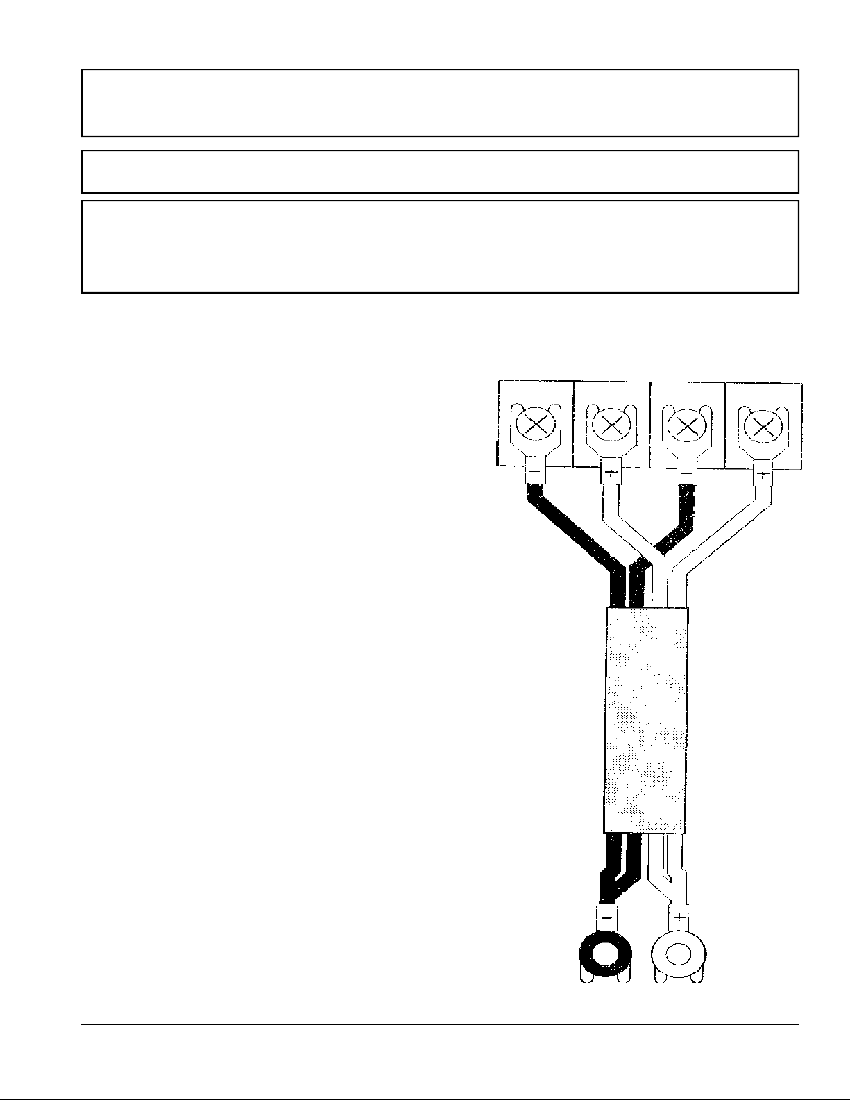
INTERNAL BI-WIRE CONNECTIONS
If your domestic situation dictates the use of a single cable
per speaker, you should use a multiple conductor single-sheath
cable to internally bi-wire the speakers. Some of these cables use
different types of wire for the upper and lower ranges of the
speaker and may affect the blend between the midbass and midrange drivers. They should only be used after you audition them
in your system and verify that they do not affect the midbass to
midrange blending and that you like their sonic characteristics.
Please review the information on page 4 regarding cable selection and connection techniques before you connect your
speakers.
1. Crimp and solder spade lugs to the speaker ends of the ca ble from the amplifier.
2. Connect one positive and one negative wire to the tweeter/
midrange terminals on the right carefully observing proper
polarity.
3. Connect the remaining positive and negative wires to the
two left terminals carefully observing proper polarity.
4. Connect the wires in proper polarity to the same set of out puts on your amplifier. If possible, use a single spade lug to
connect both positive wires and a single spade lug to con nect both negative wires to the amplifier as shown in the
diagram to the right.
MID BASS
BASS
TWEETER
MID RANGE
WE RECOMMEND
a. The speaker cables should be as short as possible and the
same length. Consider putting the amplifier between the
speakers rather than off to one side.
b. If your amplifier has multiple impedance taps, try
the 4 ohm taps and 8 ohm taps to see which sound
better. (They will sound different.) The Quatro is an
easy load and always stays between 4 and 8 ohms so
there is no danger of damaging your amplifier or the
speakers by using either set of taps. Both cables must
be connected to the same rated taps on the amplifier.
c. True bi-wire for optimum performance.
VANDERSTEEN AUDIO 6
AMPLIFIER
TERMINALS
Page 7

With their extensive subwoofer controls and room compensation adjustments, the
Quatros low frequency response can be optimized for any placement. The speakers’
positioning will affect the midbass, midrange, and treble performance with some positions offering better imaging and superior frequency balance and detail. With the
tremendous variables in room construction and layout, there are no magical formulas for determining the best speaker placement in every room. We recommend that
you try the speakers in every domestically acceptable location to find their best midbass to treble performance in your particular listening environment. The odd dimensions placement method covered in the following sections is a tool that can help
you find an acceptable placement, but to find the optimum placement, you will need
to invest the time and effort to try all the possible placements in the room.
Before you begin your positioning experiments, verify that the speakers are connected to the amplifier in proper polarity and that the M5-HP crossover is in place
and properly set for the input impedance of the amplifier. The cones should not be
installed. Set the speakers on flat cookie sheets so that they will easily slide on the
carpet from position to position. To insure that the bass performance of different
placements does not bias your judgment of the midbass, midrange, and treble, all
placement experiments should be performed with the subwoofer amplifier unplugged.
Carefully listen to the imaging and midbass to treble performance of each possible
placement with your reference quality music recordings. Without the subwoofer sections, the speakers will have the frequency balance of high-quality mini-monitors
and should be evaluated as such. Listen for detail, clarity, naturalness, and the overall presentation of the music. Keep notes on the different placements to help track
where the speakers sound the best.
SPEAKER PLACEMENT
When you place a given loudspeaker, either front ra-
diating or dipole, into a typical domestic environment,
the room effects the performance of the speaker. Some of
these effects are due to the speakers relationship to the
physical dimensions of the room and can be significantly
affected by placement. Every distance from the source of
sound (drivers) to a boundary (wall) has an effect. Odd
dimensions placement assures that no two boundary effects build on each other.
ODD DIMENSIONS PLACEMENT
A method that helps find possible placements in many
rooms is positioning the loudspeakers on the odd dimensional intersections of the room. The odd dimensional
intersections are where lines representing the length and
width of your room divided by odd numbers would
cross.
As an example, we will use a rectangular room meas-
uring 14 feet wide by 18 feet long. We’ll assume that you
want to set the speakers on one of the short walls, although this method works equally well for long wall
placement.
The first step is to take the length of the room, (18 feet
in our example) convert it from feet to inches, (18 X 12 =
216) and divide the result by odd numbers.
216 divided by 3 is 72 (all to the nearest inch)
216 divided by 5 is 43
216 divided by 7 is 31
216 divided by 9 is 24
216 divided by 11 is 20
(and so on; eventually the lines pile on top of each
other or the speaker gets too close to the wall to
access the rear connections and controls.)
The results are the distances in inches that the top front
7 Quatro Operation Manual
Page 8
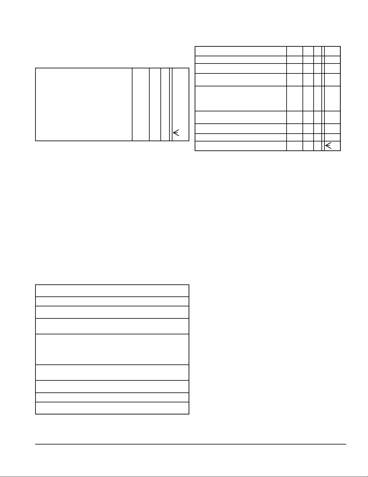
center of the speaker’s wood top should be away from the
wall behind the speaker.
Now we can graph these odd dimension distances on a
drawing of the room. We only need to graph them for the
wall where we intend to place the speakers.
20
72 43 31 24
We use the same method to figure how far the front cen-
ter of the speaker’s wood top should be from the side walls.
We take the width of the room, (14 feet) convert it from
feet to inches, (14 x 12 = 168) and divide the result by odd
numbers.
168 divided by 3 is 56 (all to the nearest inch)
168 divided by 5 is 34
168 divided by 7 is 24
168 divided by 9 is 19
168 divided by 11 is 15
The results of these odd number divisions are the dis-
tances in inches that the front center of each speaker’s
wood top should be away from the side wall.
Now we can graph these odd dimensions distances on a
drawing of the room.
15
24
34
56
56
34
24
15
By overlaying the width and length graphs, we can see
the intersection points of the lines. These points represent
where the front centers of the speakers’ wood tops should
be.
15
24
34
56
56
34
24
15
20
72 43 31 24
As you can see, we now have quite a few intersections
to choose from in our example room. In your room, some
of the intersections will be impossible to try or eliminated
due to domestic considerations.
As you try different placements for your speakers, always place both speakers on the same length line. For
example, both speakers would be placed on 43 inch line
or both speakers would be placed on the 24 inch line. The
speakers can be placed on different width lines, for example one on the 34 inch line and the other on the 56 inch
line. Placing the speakers on different rather than matching width lines will require that the listening position be
offset to center it between the speakers. Often the imaging
will be better with the speakers placed on matching width
lines.
After listening to the speakers centered on the charted
intersections, you should listen with the speakers a few
inches away from the intersection points in each direction.
In some cases, the speakers will sound better slightly off
the intersections due to the particular characteristics of
your room or a slight error in your original room measurements. Both speakers should be moved the same amount
forward or backward to maintain a consistent listener to
speaker distance when fine-tuning placement.
Several factors influence how speakers interface with a
room other than the room’s basic dimensions so it is possible that none of the placement options on the wall you
initially place the speakers on will sound quite right. The
sound may be too forward or too withdrawn or the imaging may not be to your liking. If you are unable to
achieve satisfactory sound with the speakers placed on
one wall, try placing the speakers on a different wall of
the room. Even in a rectangular room, the speakers will
interface differently with the room depending upon which
of the four walls they are placed. In some rooms the
speakers will sound best placed on a short wall, while in
other rooms the speakers will work better on a long wall.
Vandersteen AUDIO 8
Page 9
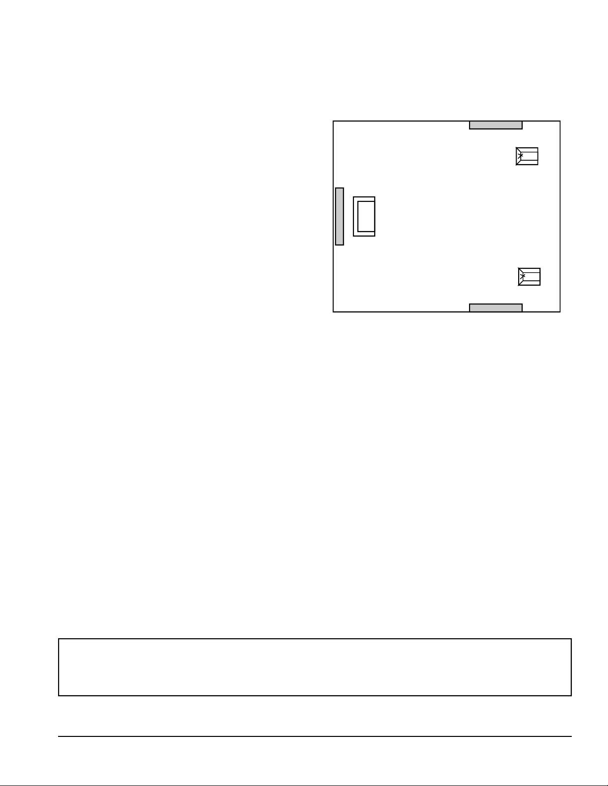
ACOUSTICAL CENTER
The Quatro’s acoustical center is at the front center of
the wood top. In a perfectly rectangular room with absolutely rigid walls and no doors or windows, the acoustical
center of the loudspeaker would be placed exactly at the
point where the two dimensions intersect to realize the
full benefits of odd dimensions placement. In a real room,
the actual best placement may vary from the intersection
by several inches. Fine-tuning the placement by moving
the speakers a few inches off the calculated intersections
takes these real world conditions into account.
You should not use any placements that put the acoustical center of the loudspeaker the same approximate distance from the rear and side walls or where one distance is
a multiple of the other. In our example room, this would
eliminate the intersection of the 24 inch width and length
lines since they are both the same distances from their
respective walls. It would also eliminate the intersection
of the 24 inch width line and 72 inch length line because
72 is a multiple of 24. (3 x 24 = 72) If any of the odd dimension intersections in your room are within a few
inches of being the same distance from the side and rear
walls or multiples of each other, you should not use them.
SPEAKER TOE-IN
The degree of toe-in can affect the imaging and response characteristics of the speakers. In most rooms, the
speakers will work well facing straight ahead or with a
slight to moderate toe-in. Speakers that are placed close to
the side walls or in rooms with very reflective side walls
may require additional toe-in to avoid a confused image
and/or a forward midrange and treble. Although rare, in
some rooms the speakers may actually perform better with
a slight amount of toe-out.
ACOUSTIC TREATMENTS
If the speakers are close to the side walls and you hear
a brightness in the midrange/treble or a problem with the
imaging that toeing-in the speakers does not help, some
sound absorbent material should be mounted on the side
walls to control reflections.
To determine where the sound absorbent material
should be placed, imagine that the walls are mirrors and
mount the material on the walls where you would
see the reflections of the speakers when you are sitting
in your normal listening position. Before you actually
mount anything on the side walls, experiment with
folded natural-fiber blankets to verify that you will get
the results you desire.
Speaker
Listening
Position
If your listening position is close to the wall behind
you, mount some sound absorbent material, such as a
hanging tapestry, directly behind your head. As with
the material for the side walls, experiment with a pillow or a folded natural-fiber blanket to verify the results before you acquire or mount the material.
Speaker
HELPFUL HINTS
A. To try the speakers on different walls, set your
equipment in the middle of the room so the
speaker cables can reach each possible location.
B. When you change the placement of the speakers,
listen to several different reference quality music
recordings before judging the results of the
change.
C. If you set the speakers on a wood floor, consult
your dealer about how to protect the floor from
damage.
D. Don’t over-analyze the sound of each placement.
When the sound is right, it will be obvious.
E. Keep notes on the sound of different placements
you try. It is easy to get mixed-up and forget
which placement sounded the best.
The Quatros break-in and significantly improve during the first 100 hours of use.
Until this period has elapsed, the speakers exhibit some sonic aberrations as the parameters of the Quatro were established with completely broken-in drivers.
9 Quatro Operation Manual
Page 10
INSTALLING THE CONES & LISTENING
HEIGHT ADJUSTMENTS
The Quatro is supported by two cones, one in each front
corner and one spike in the rear center. The cones and spike
thread directly into the bottom of the speaker and provide
stability and proper coupling to the floor. Two people are
required to safely install the cones and spike. Do not attempt
to install them by yourself.
All properly aligned loudspeakers have a vertical listening
window where their sound is optimized. The Quatro’s six
inch high optimum listening window is centered at 35
inches when the speaker is vertical. If your ear height is
above or below 35
1/2 inches at your normal listening position,
the speakers should be tilted to center the optimum listening
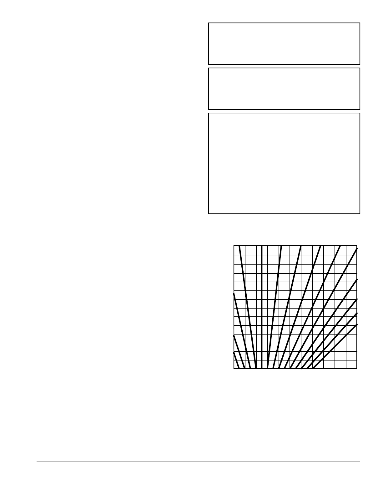
window at your ear height. The chart to the right shows how
many spacers should be inserted between the rear spike and
the speaker to tilt the speaker for different ear heights and
listening distances.
1. Measure the distance from the listening position to the
speakers and the height of your ears when you are seated
at your listening position. (Ear height is roughly equal to
the height of the tip of your nose).
2. Find the values closest to your actual measurements on
the chart to the right.
3. Follow the horizontal line across from your listening
distance and the vertical line up from your ear height to
the point where they intersect. The heavy lines are numbered to indicate how many spacers should be inserted
between the rear spike and the bottom of the Quatro to
center the listening window at your listening height and
distance.
4. Lean the speaker to one side as one person supports the
main body of the speaker. Do not touch the front grille
to support the speaker.
5. Install two cones into the threaded holes on each front
corner. Be careful not to cross-thread the cone, it
should go in easily. By hand, tighten the cone snug up
against the bottom of the speaker. Do not adjust right
or left tilt on a uneven floor without some kind of shim.
The weight of the speaker must not be on the threads of
the cone.
6. Place the number of washers indicated for the rear spike
on a cone and tread it into the rear center of the speaker.
Hand tighten it against the bottom of the speaker.
7. Set the speaker up-right.
8. Sight across the front of the speaker’s woofer boxes and
verify they are both tilting at the same angle. Some adjustments of the washers on one speaker may be
needed. It is important that both speakers are perfectly
parallel with each other.
9. The two small holes (1/4 - 20) at the rear flanking the
center spike are for stability. Install the small spikes but
do not allow them to touch the floor. If the tilt chart calls
for significant tilt, the outrigger spikes are not required.
1/2
Improper listening height can cause
the speakers to sound extremely
bright or dull.
Two people are required to safely install the cones and spike. Do not attempt to install the cones by yourself.
Be careful not to cross thread the
cones as you install them into the bottom of the Quatro. The cones should
turn easily by hand. Damaged
threads can be repaired with a 1/4-20
thread tap. A stuck cone can be removed by turning it with a nail or
small screwdriver inserted through
the cross hole.
DISTANCE FROM EARS TO FRONT OF SPEAKER TOP
10
20
19
18
17
16
15
11
14
13
12
11
10
12
9
8
13
7
6
33 35 34 36 37 38 39 40 41 42 43 44
HEIGHT IN INCHES TO EAR
9
8
7
6
5
AN EXAMPLE
In a room where the listening position was 15 1/2 feet
away from the speakers and your ear height was 39 1/2
inches, the lines would intersect as shown by the
dashed lines on the graph. Since the intersection is
closest to the 6 line, you would place 6 spacers on the
rear spike.
4
3
2
1
0
VANDERSTEEN AUDIO 10
Page 11

PLUGGING-IN THE SUBWOOFER AMPLIFER
With the speaker cables connected, the M5-HP crossover in place, the placement established, and the cones
installed, the Quatro’s subwoofer amplifier should be
plugged-in. The amplifier uses a removable power cord
that should be securely inserted into the amplifier and
then plugged into a non-switched outlet that is known to
be operating properly. If an extension cord is required, it
should be as short as possible and constructed of 14
gauge or larger wires. As the amplifier is plugged-in, it
will usually produce a thump or pop from the subwoofer driver.
During electrical storms or when the system will
not be used for a long period of time, (i.e. vacations)
the Quatro amplifier should be unplugged along with
the other components in the system.
LOW-FREQUENCY ROOM OPTIMIZATION AND LEVEL
The eleven room compensation controls located on th e
rear input plate help counter the amplitude and phase effects
of room nodes and anti-nodes and provide the most linear
low frequency response at the listening position. They can
only be calibrated S.P.L. Meter with matching disc. Once
the controls have been set for a particular room, they should
TECHNICIAN’S ADJUSTMENT SECTION (ONLY FOR QUALIFIED TECHNICIANS)
Only a qualified technician with a calibrated S.P.L. Meter and matching test
disc should adjust the room compensation controls. This procedure can
take several hours.
not need to be readjusted unless the speaker placement
and/or listening position are significantly changed.
The low-frequency level and contour can be set by
the user using a specific type of music as detailed on
page 12.
The steady state test signal can
cause the Quatro amplifier to run
warm. Verify that the SN# on the
S.P.L. Meter match the SN# on the
test disc.
TECHNICIAN’S GUIDE TO ADJUSTING THE ROOM COMPENSATION
AND LOW-FREQUENCY LEVEL CONTROLS.
1. Set the S.P.L Meter at the listening position at ear height.
Turn on the S.P.L. Meter to the 70dB scale, “C” weighting, “Slow” response.
2. Insert test disc into a CD Player, set the volume on the
preamp to a low level.
3. On the Quatro Amplifier set the low frequency contour
control to minimum (#1) and verify that all eleven room
compensation band are set straight up (slot vertical). Set
low frequency level to 0dB.
4. Play tracks one through eleven and note on paper the
meter readings for all eleven tracks. Adjust the preamp
volume up or down until two thirds of the tracks read
70dB or higher and one third of the tracks are 70dB or
lower. This is your reference volume do not adjust
until this entire calibration is complete for both
speakers.
5. Play track one through eleven and adjust each band to
25% of the meter reading noted in step # 4.
Play tracks:
Meter Reading:
Noted Step # 4:
Adjust Bands
To APX 25%
1 2 3 4 5 6 7 8 9 10 11
+4 +6 –3 +8 +10 –6 +3 –3 +2 +1 +3
+1 +2 –1 +2.5 +3 –2 +1-1 +.5 0 +1
Note: Do not try to adjust every peak or dip all the way
to 0 dB. Our studies have shown that adjusting all the
peak and dips to 0dB can cause a non-musical sound
with audible equalization effects. Your left speaker is
now properly compensated for the room.
6. Play tracks twelve through twenty two and note on paper the meter readings for all eleven tracks. Adjust the
right Quatro Low Frequency Level Control
two thirds of the tracks read 70dB or higher and one
third of the tracks are 70dB or lower. Save this last set
of reading for use in step# 7.
7. Play tracks twelve through twenty two and adjust the
right speaker bands as in step# 5, but using the meter
reading noted in step #6. Note: Occasionally full adjustment of one or more of the bands will not adjust to
the target value for the right or left speaker, get it as
close as possible. If one or more of the bands turned
maximum up or down makes little or no difference on
the meter, leave it adjusted straight up (slot vertical).
Your speakers are now calibrated to the room.
Note: The eleven bands correspond to the frequencies below:
# 1 2 3 4 5 6 7 8 9 10 11
Frq: 20 24 30 36 42 50 60 72 84 100 120
up until
11 Quatro Operation Manual
Page 12
USER ADJUSTMENTS
Do not try to set the Room Compensation Controls by ear. Due to the complex interactions of the controls, you will only succeed in compromising the inherent accuracy of the
speakers. Unless adjusted by a qualified technician, the Room Compensation Controls
should be left straight up.
LOW-FREQUENCY LEVEL
Set the low-frequency contour control to minimum
(#1) . Select a clean jazz recording with a stand-up bass
scaling up and down. Adjust the Low-Frequency Level
controls on the speakers until the transition from the subwoofer to the upper part of the speaker is seamless and
CONTOUR CONTROL (Q CONTROL)
The contour control on the Quatro input plate allows
you to tailor the characteristics of the speaker’s bass and
to suit the listening environment and your personal taste.
Since this control alters the performance of the speaker to
match your personal taste, they should be adjusted by ear
using well recorded, accurate recordings. All the instructions for adjusting this control assume that the LowFrequency Level and Room Compensation controls have
been set by a qualified technician and the Low-Frequency
Level has been set using a jazz recording. It is also assumed that the speakers are positioned where they have
the best imaging and performance on the mid-bass to upper frequencies, that the cones and spike are installed with
the spacers required to set the speakers at your listening
height and that the high-pass crossover is in place and
properly configured.
Before we address this control and its use, we want to
point out that they are not substitutes for tone controls.
Preamplifier tone controls are designed to withstand thousands or even tens of thousands of adjustments and are the
best way to compensate for your particular tastes and the
peculiarities of individual recordings. The Quatro’s controls were chosen solely for their sonic characteristics and
have a life expectancy of hundreds rather than thousands
of uses. This should be enough to cover several lifetimes
worth of residence changes or room alterations.
The Low-Frequency Contour control adjusts the Q of
the subwoofer to accommodate different rooms, listening
tastes, or system modes. In subwoofer engineering terms,
system Q is the product of a complex mathematical equation derived from driver, electrical, and enclosure parameters. In practical terms, it relates to the character of the
bass response. A low Q subwoofer sounds very tight and
controlled. A high Q subwoofer produces a warm, full
bass with more energy in the most audible bass range.
linear. If during the room compensation calibration, the
Low-Frequency levels were different right from left by
some dB amount, raise and lower the level as needed
keeping the difference between the two.
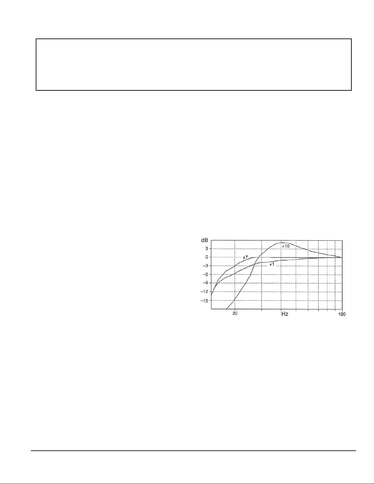
The Quatro’s Low-Frequency Contour control is leveled from 1 to 10. As shown in the graph below, position
# 1 provides the tightest bass (Lean Audiophile Sound),
position # 7 is maximally flat as measured at the driver
cone, (Linear Anechoic Response) and position # 10 emulates the peaked response of a typical high Q home theater
subwoofer (Big and Boomy.)
Our experience is that the bass in most rooms with
concrete slabs sound the most linear on high-quality music recordings with the Low-Frequency Contour set in the
# 3 to # 8 range. Rooms with wood floors (ie: Second
Floor) sound most linear with the contour set in the #1 to
#7 range. Please remember that every room and system
are different and that the nominal position in your system
may be higher or lower due to room characteristics or personal preferences.
Once you have established these settings for your system, using a reference recording (Solar Energy) your
Quatros are properly adjusted for the room. Recordings
vary so do not be tempted to readjust for different recordings, this is the function of the tone controls on the
preamp.
VANDERSTEEN AUDIO 12
Page 13

AMPLIFER REQUIREMENTS
The Quatro is designed for use with amplifiers rated
from 30 to 200 watts per channel into 8 ohms. These amplifiers will provide ample power for realistic listening
levels in most situations. Amplifiers with less than 75
watts should be tested with the volume control half the
way up (the point where most amplifiers clip) to verify
that the system can achieve realistic listening levels without stress. Amplifiers with more than 200 watts must be
used with caution due to the increased potential for
speaker damage if they are misused or an accident occurs.
The Quatros are very revealing speakers and are eas-
ily capable of showing the subtle sonic differences between amplifiers. They will perform well with a tube,
transistor, or hybrid amplifier, allowing each design to
realize its full potential.
Fuses between the amplifier and the Quatro will degrade the performance of the entire system. No fuses
are used in the Quatro and preference should be given
to the use of an amplifier that does not use output fuses.
Preamplifiers and CD players should be left on except during electrical storms or extended absences. Amplifiers should be turned off when the system is not being used.
Once broken in, modern power amplifiers sound good after only 20 minutes of
warm-up. Leaving the amplifier on all the time exposes the speakers to possible damage from power line anomalies or electrical component failure while the system is unattended.
QUATRO MAINTENANCE
CLEANING
The appearance and performance of the Quatro can be
enhanced by observing a few precautions and performing
some simple maintenance.
The input terminals on the Quatro and the spade lugs
on the speaker wire should be cleaned periodically with
alcohol or a solution made specifically for cleaning electrical contacts. Other connection points in the system
should be cleaned as per the equipment manufacturer’s
recommendations.
The grille cloth on the Quatro can be gently vacuumed
using a brush attachment that will not snag the cloth.
SERVICE
In the unlikely event that your Quatros require service,
please follow these procedures.
1. Verify that your Quatros have been set-up and connected according to the instructions in this manual.
2. Verify that the problem you are hearing is in the
speaker by switching the left and right speaker cables
at the speakers. If the problem switches sides, it is in a
component or cable rather than the speaker.
3. Play each bass input and the midrange/treble input of
the suspect speaker separately to determine which section has a problem.
4. Contact Vandersteen Audio with your Quatro’s serial
number, information on your associated components, a
description of the problem and the steps you have
taken to isolate it to the Quatro.
Be careful around the drivers on the front of the speaker.
The brush attachment could damage the drivers. The
wood should be treated as a piece of fine furniture. The
wood veneers are covered with a polyurethane clear coat
at the factory and can be maintained with a light application of Pledge or a similar product. Do not use Windex
or any product with ammonia on the Quatro.
The speakers should not be exposed to excessive heat
or direct sunlight which can damage the fit and finish of
the fine wood veneer.
5. The Quatro is a modular system. Should Vandersteen Audio determine that a subwoofer module
needs to be returned to the factory for repair, a Return Authorization form is available on our website.
6. Return the damaged or defective module or driver
and the completed Return Authorization Form to
Vandersteen Audio.
VANDERSTEEN AUDIO
116 West Fourth Street
Hanford, CA 93230
(559) 582-0324
www.vandersteen.com
13 Quatro Operation Manual
Page 14

TROUBLESHOOTING GUIDE
Problem: If the subwoofer hums audible at the listening
position.
Solution: Install 20ga ground wire between the ground ter minal of the Quatro Amplifier on the lower right
next to the A.C. connector. Connect this wire to
the chassis of the preamp or amplifier.
Problem: Subwoofer driver hums. Audible at the
listening position.
Solution: Try different grounding methods. Try floating
the ground connector on the Quatro or
main amplifier’s power cord. Only one com ponent in the system should be grounded. If float ing the ground on the Quatro Amplifier, connect a
separate ground wire between the ground terminals
of each amplifier.
Problem: Still hums, grounding changes didn’t help.
Solution: Check your interconnect cables. Route cables
away from the amplifier. Position the M5-HP
crossover away from the amplifier. Verify
that the M5-HP is properly installed in the
system. Try the system at a very low volume
level without the M5-HP. If the M5-HP is the
source of the hum, it will have to be replaced
before the system can be used.
Problem: Still hums, cable and crossover changes
didn’t help.
Solution: Disconnect the inputs from the Quatro,
if the hum is still evident at the listening posi tion, please contact Vandersteen Audio.
(It is normal for the amplifier’s high-voltage
transformer to produce a slight hum, but it
should not be audible more than a few feet
away from the speaker.)
Problem: No subwoofer output.
Solution: Verify that the Quatro subwoofer ampli fier is plugged into a live AC outlet. (It should
thump or pop when you plug it in.) Verify
that the AC cord is securely inserted into the
Quatro amplifier.
Problem: High or low subwoofer output level.
Solution: Verify the actual input impedance of the main
amplifier and that the M5-HP is correctly
matched to it. Check the low-frequency level
and contour control settings.
Problem: Quatro amplifier excessively hot.
Solution: If the amplifier does not cool down after play
ing music, remove the amplifier and return it to
Vandersteen Audio for service.
Problem: Distortion in the midrange or tweeter.
Solution: Check to see that the metal connectors on the
speaker wires are not touching the aluminum
input panel. Wire terminals should be bent to
exit at approximately 45 degrees.
COMMON QUATRO QUESTIONS
Can a subwoofer or subwoofers be added to a system
with Quatros?
The Quatros contain integral subwoofers and there
would be no benefit or advantage to adding separate subwoofers. When the Quatros are used in a home theater
system, program the processor to redirect the Low Frequency Effects (LFE) and subwoofer information to the
front channels where it will be reproduced by the Quatro
subwoofers. Vandersteen 2Wq subwoofers can be added if
more bass is needed to accommodate a large room. Please
contact Vandersteen Audio about using parallel woofers.
What speaker cables sound best with the Quatros?
The cables that sound best with your Quatros are the
cables that are most complementary to you particular associated equipment, the characteristics of your room and
your personal taste. There is no way for us to adequately
evaluate two of the three deciding factors (room and taste)
so there is no way for us to accurately predict what cables
will sound best with your Quatros.
SUPPORT
This manual has dealt with the installation, use and
capabilities of Vandersteen Quatro loudspeakers. You
should review this manual with anyone who will use the
audio system.
How will I know when an update is available for my
Quatros?
Vandersteen dealers will be notified when Quatro
updates are available. In most cases, the update will be
performed at the factory.
Should you have any questions regarding your
Quatro, you should contact Vandersteen Audio by phone
M-F 8:00am to 5:00pm Pacific Time. We will do our
best to answer your questions and address your concerns.
VANDERSTEEN AUDIO 14
Page 15
UNPACKING AND REPACKING THE QUATRO
At least two people are required to unpack or pack a pair of Quatros. Each speaker is
shipped on its own pallet and has a gross weight over 120 pounds. Please use the
handholds in the boxes and proper lifting techniques to lift and move the speakers.
There could be grease or dirt on the bottom of the cartons. Cover carpet with several
layers of newspaper or an old blanket before you set the cartons down.
The speaker must remain up-right as it is unpacked. Be careful about any fingers
contacting the top front 18” of the grill in anyway.
UNPACKING INSTURCTIONS
1. Cut the tape around the top of the box at all four corners.
2. Lift up each of the top flaps to release the main box
flaps that were anchoring the top in place and lift the
top off.
3. Lift the cardboard up and off the speaker.
4. Cut the tape around the bottom of the box at all four
corners.
5. Pull out the bottom flaps to release the main box flaps
that were holding the bottom and the main box together
and lift the main box up and off the speaker.
6. Lift the plastic bag up and off the speaker.
REPACKING INSTURCTIONS
1. Remove all cones and spikes.
2. Place the cardboard tray large recess up on the folded
bottom cover.
3. Place the plastic sheet into recess.
4. With another person helping, lift the Quatro and place it
into recess using the procedure in # 7 above.
5. Place plastic bag over the Quatro.
6. Place the main box over and secure the flaps with the
bottom.
7. Tape the bottom flaps.
8. Place the top tray over the Quatro.
9. Place the top cover over the top tray and secure the flap
to the main box.
10. Tape the top cover and main box flap. Use filament tape
for both top and bottom flaps.
11. Place both packed Quatros on master pallet and secure
them with straps. Shrink wrap the whole assembly. Do
not ship Quatros without strapping them to the master pallet.
7. With one person standing on one side and another
person on the other side, lift the speaker by tilting it
back so that each can get a hand under the bottom of
the Quatro. Each person should place their fingers
into the recesses for the cones under the front of the
speaker for grip, and place their remaining hand 3/4
of the way up the back of the Quatro still tilted ap proximately 30%. With bent knees, lift the Quatro
up and out of the cardboard tray and set it carefully
on the floor. Be careful not to drop the speaker even
a small distance as this will result in damage to the
bottom.
Please keep the boxes, pallets and hardware. Replacement boxes and pallets must
be shipped by truck and will cost at least
Fold
$250.00
Top Tray
Top Cover
Main Box
Quatro
Bottom Tray
Bottom Cover
Fold
15 Quatro Operation Manual
Page 16

LIMITED ONE YEAR WARRANTY
VANDERSTEEN AUDIO loudspeakers are warranted to the original purchaser to be free from defects in materials or
workmanship, SUBJECT TO THE FOLLOWING CONDITIONS, for one (1) year from the date of purchase from an
authorized VANDERSTEEN AUDIO dealer.
THIS WARRANTY IS SUBJECT TO THE FOLLOWING CONDITIONS AND LIMITATIONS:
This warranty is void and inapplicable if the loudspeaker has:
A. Not been used in accordance with the instructions contained in the operation manual.
B. Been subject to misuse or abuse; examples of which would be burned driver voice coils or burned crossov er com po-
nents.
C. Been modified, repaired, or tampered with by anyone not specifically authorized to do so by Vandersteen Audio.
D. Been subject to inputs in excess of the maximum rating, or inputs from an unstable or clipped amplifier.
E. Suffered physical damage to the structure or components due to accident, neglect, or transportation.
IF A VANDERSTEEN AUDIO LOUDSPEAKER FAILS TO MEET THE ABOVE WARRANTY AND THE ABOVE
CONDITIONS HAVE BEEN MET, THEN THE CUSTOMER’S SOLE REMEDY SHALL BE TO RETURN THE
PRODUCT TO VANDERSTEEN AUDIO WHERE THE DEFECT WILL BE REPAIRED WITHOUT CHARGE FOR
PARTS OR LABOR. THIS WARRANTY APPLIES ONLY TO PRODUCTS RETURNED TO VANDERSTEEN AUDIO IN HANFORD, CA USA.
(Returning the product to Vandersteen Audio from some countries other than the United States may involve considerable
time and expense. The customer is responsible for all fees and duties and for providing instructions and all the paperwork
required to return the product after it is serviced.)
The speaker must be packed in the original packing and returned to VANDERSTEEN AUDIO via insured freight by the
customer at his or her own expense. A returned product must be accompanied by a Return Authorization Form, (available
from VANDERSTEEN AUDIO upon request) which includes a written description of the defect and return shipping
information.
ANY IMPLIED WARRANTIES RELATING TO THE ABOVE PRODUCT SHALL BE LIMITED TO THE DURATION OF THE ABOVE WARRANTY. THIS WARRANTY DOES NOT EXTEND TO ANY INCIDENTAL OR CONSEQUENTIAL COSTS OR DAMAGES TO PURCHASER.
Some states do not allow limitations on how long an implied warranty lasts, or an exclusion of incidental or consequential damages so the above limitations or exclusions may not apply. This warranty gives you specific legal rights, you may
also have other rights in your state.
VANDERSTEEN AUDIO reserves the right to modify the design of any product without any obligation to previous purchasers and/or to change the prices or specifications without notice or obligation to anyone.
A PERSONAL NOTE
I have been doing volunteer work for several years with elderly people with severe hearing
losses, and I have seen the frustration and anger that are brought on by these loses. We
now know that many of these people developed their hearing problems because of exposure to high noise levels when younger.
Many home stereo systems, as well as audio/video, personal, and automobile sound systems are capable of volume levels potentially damaging to your hearing. Please use common sense, and listen to your music and movies at safe levels now so you will still have
the ability to hear and enjoy them in the future.
Richard Vandersteen
Quatro Operation Manual Copyright 2005 Vandersteen Audio, Inc.
 Loading...