

Vanderbilt SPC6, SPC5, SPC6350.320, SPC4000, SPC6330.320 Installation & Configuration Manual
...Page 1
SPC4xxx/5xxx/6xxx
Installation & Configuration Manual
Document ID: A6V10276959-d
Edition date: 12.09.2018
Page 2

Data and design subject to change without notice. /Supply subject to availability.
© 2018 Copyright by Vanderbilt InternationalLtd.
We r eserve allrights in this document and in the subject thereof. By acceptance of the document the recipient acknowledges these rights and
undertakes not to publish the document nor the subject ther eof in full or in part, nor to make them available to any third party without our pr ior
express written authorization, nor to use it for any purpose other than for which it was delivered to him.
Page 3

Table of Contents
Table of Contents 3
1 Meaning of symbols 10
2 Security 11
2.1 Target group 11
2.2 General safety instructions 11
2.2.1 General information 11
2.2.2 Transport 11
2.2.3 Setup 12
2.2.4 Operation 12
2.2.5 Service and maintenance 12
2.3 Meaning of written warning notices and hazard symbols 12
2.3.1 Warning notices 12
2.3.2 Hazard symbols 13
3 Directives and standards 14
3.1 EU directives 14
3.2 Overview of Conformity to EN50131 Standard 14
3.2.1 Compliance with EN50131 Approvals 20
3.3 Compliance with EN 50136-1:2012 and EN 50136-2:2014 22
3.4 Compliance with INCERT Approvals 22
3.5 PD 6662:2010 Conformance Guidelines 23
3.5.1 Product scope 23
3.5.2 Standards overview 24
3.5.3 Methods for the completion of setting and unsetting 24
3.5.4 Configuration requirements for PD 6662:2010 conformance 26
3.5.5 Additional commissioning requirements for PD 6662:2010 conformance 27
3.5.6 Additional information 27
3.6 Compliance with VdS approvals 28
3.7 Compliance with NF and A2P approvals 29
4 Technical Data 31
4.1 SPC4000 31
4.2 SPC5000 33
4.3 SPC6000 37
4.4 SPCP355.300 40
5 Introduction 42
6 Mounting system equipment 43
6.1 Mounting a G2 housing 43
6.2 Mounting a G3 housing 44
© Vanderbilt 2018 3 A6V10276959-d
12.09.2018
Page 4

SPC4xxx/5xxx/6xxx – Installation & Configuration Manual Table of Contents
6.2.1 Mounting a Back Tamper Kit 46
6.2.2 Battery installation for EN50131 compliance 50
6.3 Mounting a G5 housing 51
6.3.1 Tamper protection 52
6.3.2 Mounting the housing with tamper protection 53
6.3.3 Installing the batteries 55
6.4 Mounting a keypad 56
6.5 Mounting an expander 56
7 Smart PSU 57
7.1 SPCP355.300 Smart PSU 57
7.1.1 Supervised Outputs 59
7.1.2 Batteries 60
7.1.3 Wiring the X-BUS Interface 62
7.1.4 Compliance with NF and A2P approvals 65
7.1.5 PSU LED Status 66
7.1.6 System Recovery 67
8 Controller hardware 68
8.1 Controller Hardware 42xx/43xx/53xx/63xx 68
8.2 Controller Hardware SPC5350 and 6350 70
9 Door Expander 74
10 Wiring the system 75
10.1 Wiring the X-BUS interface 75
10.1.1 Loop configuration 76
10.1.2 Spur configuration 77
10.1.3 Star and multi-drop configuration 78
10.1.4 Shielding 83
10.1.5 Cable Map 83
10.2 Wiring of branch expander 83
10.3 Wiring the system ground 84
10.4 Wiring the relay output 84
10.5 Wiring the zone inputs 85
10.6 Wiring an external SAB bell 88
10.7 Wiring an internal sounder 89
10.8 Wiring Glassbreak 89
10.9 Installing plug-in modules 90
11 Powering up the SPC controller 92
11.1 Powering from battery only 92
12 Keypad user interface 93
12.1 SPCK420/421 93
© Vanderbilt 2018 4 A6V10276959-d
12.09.2018
Page 5

SPC4xxx/5xxx/6xxx – Installation & Configuration Manual Table of Contents
12.1.1 About the LCDkeypad 93
12.1.2 Using the LCD keypad interface 95
12.1.3 Data entry on the LCD keypad 98
12.2 SPCK620/623 99
12.2.1 About the Comfort keypad 99
12.2.2 LED description 103
12.2.3 Viewing mode description 103
12.2.4 Function keys in idle state 104
13 Software support tools 105
14 Starting the system 106
14.1 Engineer modes 106
14.1.1 Engineer PINs 106
14.2 Programming with the keypad 106
14.3 Configuring start-up settings 107
14.4 Creating system users 108
14.5 Programming the portable ACE 109
14.6 Configuring wireless fob devices 110
14.6.1 Clearing alerts using the fob 110
15 Soft Engineer programming via the keypad 111
16 Engineer programming via the keypad 112
16.1 System Status 112
16.2 Options 113
16.3 Timers 117
16.4 Areas 121
16.5 Area Groups 123
16.6 X-BUS 123
16.6.1 X-BUS Addressing 123
16.6.2 XBUS Refresh 124
16.6.3 Reconfigure 124
16.6.4 Keypads/Expanders/Door Controllers 125
16.6.5 Addressing Mode 133
16.6.6 XBUS Type 134
16.6.7 Bus Retries 134
16.6.8 Comms Timer 135
16.7 Users 135
16.7.1 Add 135
16.7.2 Edit 135
16.7.3 Delete 138
16.8 User Profiles 138
© Vanderbilt 2018 5 A6V10276959-d
12.09.2018
Page 6

SPC4xxx/5xxx/6xxx – Installation & Configuration Manual Table of Contents
16.8.1 Add 138
16.8.2 Edit 138
16.8.3 Delete 139
16.9 Wireless 140
16.9.1 Select a wireless programming option 141
16.9.2 One-way wireless 142
16.9.3 Two-way wireless 146
16.10 Zones 149
16.11 Doors 149
16.12 Outputs 153
16.12.1 Outputs types and output ports 154
16.13 Communication 158
16.13.1 Serial Ports 158
16.13.2 Ethernet Ports 158
16.13.3 Modems 159
16.13.4 Central Station 161
16.13.5 SPCConnect PRO 163
16.14 Test 163
16.14.1 Bell Test 163
16.14.2 Walk Test 163
16.14.3 Zone Monitor 164
16.14.4 Output Test 165
16.14.5 Soak Test 165
16.14.6 Audible Options 165
16.14.7 Visual Indicators 166
16.14.8 Seismic Test 166
16.15 Utilities 166
16.16 Isolate 167
16.17 Event Log 167
16.18 Access Log 167
16.19 Alarm Log 167
16.20 Change Engineer Pin 168
16.21 SMS 168
16.21.1 Add 169
16.21.2 Edit 169
16.21.3 Delete 170
16.22 X-10 170
16.23 Set Date/Time 170
16.24 Installer Text 171
© Vanderbilt 2018 6 A6V10276959-d
12.09.2018
Page 7

SPC4xxx/5xxx/6xxx – Installation & Configuration Manual Table of Contents
16.25 Door Control 171
16.26 SPC Connect 171
17 Engineer programming via the browser 173
17.1 System Information 173
17.2 Ethernet interface 173
17.3 Connecting to the panel via USB 175
17.4 Logging into the browser 177
17.5 SPC Home 178
17.5.1 System Summary 178
17.5.2 Alarms Overview 179
17.5.3 Viewing Video 179
17.6 Panel status 180
17.6.1 Status 180
17.6.2 X-Bus Status 181
17.6.3 Wireless 188
17.6.4 Zones 191
17.6.5 Doors 192
17.6.6 FlexC Status 193
17.6.7 System alerts 195
17.7 Logs 195
17.7.1 System Log 195
17.7.2 Access Log 196
17.7.3 ALARM LOG 196
17.8 Users 197
17.8.1 Adding/Editing a User 197
17.8.2 Adding/Editing User Profiles 200
17.8.3 Configuring SMS 204
17.8.4 SMS Commands 205
17.8.5 Deleting Web Passwords 208
17.8.6 Configuring Engineer Settings 208
17.9 Wireless 211
17.9.1 One-way wireless 212
17.9.2 Two-way wireless 222
17.10 Configuration 231
17.10.1 Configuring controller inputs and outputs 231
17.10.2 X-BUS 241
17.10.3 Changing system settings 255
17.10.4 Configuring zones, doors and areas 272
17.10.5 Calendars 287
© Vanderbilt 2018 7 A6V10276959-d
12.09.2018
Page 8

SPC4xxx/5xxx/6xxx – Installation & Configuration Manual Table of Contents
17.10.6 Change own PIN 290
17.10.7 Configuring advanced settings 290
17.11 Configuring Communications 298
17.11.1 Communications Settings 298
17.11.2 FlexC® 308
17.11.3 Reporting 328
17.11.4 PC Tools 341
17.12 File Operations 343
17.12.1 File Upgrade Operations 343
17.12.2 File Manager Operations 347
18 Accessing web server remotely 349
18.1 PSTN connection 349
18.2 GSM connection 351
19 Intruder alarm functionality 354
19.1 Financial mode operation 354
19.2 Commercial mode operation 354
19.3 Domestic mode operation 355
19.4 Full and local alarms 355
20 System examples and scenarios 357
20.1 When to use a common area 357
21 Seismic Sensors 359
21.1 Seismic Sensor Testing 360
21.1.1 Manual and Automatic Test Process 360
21.1.2 Automatically Testing Sensors 360
21.1.3 Manually Testing Sensors 361
22 Blocking Lock Operation 363
22.1 Blocking Lock 363
22.2 Authorized Setting of the Blocking Lock 364
22.3 Locking Element 365
23 Appendix 367
23.1 Network cable connections 367
23.2 Controller status LEDs 368
23.3 Powering expanders from the auxiliary power terminals 369
23.4 Calculating the battery power requirements 370
23.5 Domestic, Commercial and Financial mode default settings 372
23.6 Wiring of the X10 interface 373
23.7 SIA Codes 374
23.8 CID Codes 379
23.9 Overview of keypad types 381
© Vanderbilt 2018 8 A6V10276959-d
12.09.2018
Page 9

SPC4xxx/5xxx/6xxx – Installation & Configuration Manual Table of Contents
23.10 User PIN combinations 382
23.11 Duress PINs 382
23.12 Automatic inhibits 382
23.12.1 Zones 382
23.12.2 Access PINs 383
23.12.3 Engineer Access 383
23.12.4 Keypad User Logoff 383
23.13 Wiring of mains cable to the controller 383
23.14 Maintenance controller 383
23.15 Maintenance Smart PSU 384
23.16 Zone types 385
23.17 Zone attributes 390
23.18 Applicable attributes to zone types 393
23.19 ATS levels and attenuation specifications 394
23.20 Supported card readers and card formats 394
23.21 SPC Support for E-Bus Devices 396
23.21.1 Configuring and Addressing E-Bus Devices 397
23.22 FlexC Glossary 399
23.23 FlexC Commands 400
23.24 ATS Category Timings 403
23.25 ATP Category Timings 404
24 Notes 406
© Vanderbilt 2018 9 A6V10276959-d
12.09.2018
Page 10

1 Meaning of symbols
There are several symbols in the document:
Symbol Description
Not available for SPC42xx, SPC43xx.
Only available for SPC controller with IP interface
(SPC43xx/SPC53xx/SPC63xx).
Not available for installation type Domestic.
Only available in unrestricted mode.
Find further information about Security Grade, Region or Mode in text.
See Appendix for further information.
© Vanderbilt 2018 10 A6V10276959-d
12.09.2018
Page 11
2 Security
This chapter covers:
2.1 Target group 11
2.2 General safety instructions 11
2.3 Meaning of written warning notices and hazard symbols 12
2.1 Target group
The instructions in this documentation are directed at the following target group:
Target
readers
Installation
personnel
Operational
startup
personnel
Qualification Activity
Technical training for building or electrical
installations.
Has appropriate technical training with
regard to the tasks and the products,
devices or systems to be put in service.
2.2 General safety instructions
WARNING: Before starting to install and work with this device, read the Safety Instructions. This
device shall only be connected to power supplies compliant to EN60950-1, chapter 2.5 ("limited power
source").
2.2.1 General information
l Keep this document for later reference.
Assembles and installs the
hardware components on site.
Puts the device or system
which is readily assembled and
installed on site into service.
Condition of the
equipment
Individual components
that need to be
assembled and
installed.
New, readily
assembled and
installed device or
modified device.
l Always pass this document on together with the product.
l Also take into account any additional country-specific, local safety standards or regulations
concerning project planning, operation and disposal of the product.
Liability claim
l Do not connect the device to the 230V supply network if it is damaged or any parts are missing.
l Do not make any changes or modifications to the device unless they are expressly mentioned in this
manual and have been approved by the manufacturer.
l Use only spare parts and accessories that have been approved by the manufacturer.
2.2.2 Transport
Unit damage during transport
l Keep the packaging material for future transportation.
l Do not expose the device to mechanical vibrations or shocks.
© Vanderbilt 2018 11 A6V10276959-d
12.09.2018
Page 12

SPC4xxx/5xxx/6xxx – Installation & Configuration Manual Security
2.2.3 Setup
Radio interference with other devices in the environment/EMS
l When handling modules that are susceptible to electrostatic discharge, observe the ESD
guidelines.
Damage due to unsuitable mounting location
l The environmental conditions recommended by the manufacturer must be observed.
See Technical Data on page31.
l Do not operate the device close to sources of powerful electromagnetic radiation.
Danger of electrical shock due to incorrect connection
l Connect the device only to power sources with the specified voltage. Voltage supply requirements
can be found on the rating label of the device.
l Ensure that the device is permanently connected to the electricity supply; a readily accessible
disconnect device must be provided.
l Ensure that the circuit that the device is connected to is protected with a 16A (max.) fuse. Do not
connect any devices from other systems to this fuse.
l This device is designed to work with TN power systems. Do not connect the device to any other
power systems.
l Electrical grounding must meet the customary local safety standards and regulations.
l Primary supply cables and secondary cables should be routed such that they do not run in parallel or
cross over or touch one anther inside the housing.
l Telephone cables should be fed into the unit separately from other cables.
Risk of cable damage due to stress
l Ensure that all outgoing cables and wires are sufficiently strain-relieved.
2.2.4 Operation
Dangerous situation due to false alarm
l Make sure to notify all relevant parties and authorities providing assistance before testing the
system.
l To avoid panic, always inform all those present before testing any alarm devices.
2.2.5 Service and maintenance
Danger of electrical shock during maintenance
l Maintenance work must only be carried out by trained specialists.
l Always disconnect the power cable and other cables from the main power supply before performing
maintenance.
Danger of electrical shock while cleaning the device
l Do not use liquid cleaners or sprays that contain alcohol, spirit or ammonia.
2.3 Meaning of written warning notices and hazard symbols
2.3.1 Warning notices
Signal Word Type of Risk
DANGER Danger of death or severe bodily harm.
© Vanderbilt 2018 12 A6V10276959-d
12.09.2018
Page 13

SPC4xxx/5xxx/6xxx – Installation & Configuration Manual Security
Signal Word Type of Risk
WARNING Possible danger of death or severe bodily harm.
CAUTION Danger of minor bodily injury or property damage
IMPORTANT Danger of malfunctions
2.3.2 Hazard symbols
WARNING: Warning of hazard area
WARNING: Warning of dangerous electrical voltage
© Vanderbilt 2018 13 A6V10276959-d
12.09.2018
Page 14

3 Directives and standards
This chapter covers:
3.1 EU directives 14
3.2 Overview of Conformity to EN50131 Standard 14
3.3 Compliance with EN 50136-1:2012 and EN 50136-2:2014 22
3.4 Compliance with INCERT Approvals 22
3.5 PD 6662:2010 Conformance Guidelines 23
3.6 Compliance with VdS approvals 28
3.7 Compliance with NF and A2P approvals 29
3.1 EU directives
This product complies with the requirements of the European Directives 2004/108/EC “Directive of
Electromagnetic Compatibility”, 2006/95/EC “Low Voltage Directive”, and1999/5/EC on Radio and
Telecommunications Terminal Equipment (R&TTE). The EU declaration of conformity is available to the
responsible agencies at http://pcd.vanderbiltindustries.com/doc/SPC
European Directive 2004/108/EC “Electromagnetic Compatibility”
Compliance with the European Directive 2004/108/EC has been proven by testing according to the
following standards:
emc emission EN 55022 Class B
emc immunity EN 50130-4
European Directive 2006/95/EC “Low-Voltage Directive”
Compliance with the European Directive 2006/95/EC has been proven by testing according to the
following standard:
Safety EN 60950-1
3.2 Overview of Conformity to EN50131 Standard
This section gives an overview of the SPC compliance to the EN50131 standard.
Address of Certifying Body
VdS (VdS A/C/EN/SES Approval)
AG Köln HRB 28788
Sitz der Gesellschaft:
Amsterdamer Str. 174, 50735 Köln
Geschäftsführer:
Robert Reinermann
JörgWilms-Vahrenhorst (Stv.)
SPC products listed have been tested according to EN50131-3:2009 and all relevant RTC specifications.
© Vanderbilt 2018 14 A6V10276959-d
12.09.2018
Page 15

SPC4xxx/5xxx/6xxx – Installation & Configuration Manual Directives and standards
Product Type Standard
l SPC6350.320
l SPC6330.320
l SPC5350.320
l SPC5330.320
l SPCP355.300
l SPCP333.300
l SPCE652.100
l SPCK420.100
l SPCK421.100
l SPCE452.100
l SPCE110.100
l SPCE120.100
l SPCA210.100
l SPCK620.100
l SPCK623.100
l SPCN110.000
l SPCN320.000
EN50131 Grade 3
l SPC5320.320
l SPC4320.320
l SPCP332.300
l SPCW110.000
l SPCW112.000
l SPCW114.000
l SPCW130.100
EN50131 Grade 2
Specific information in relation to EN50131 requirements can be found in the following sections in this
document.
EN50131 Requirement (and relevant section) Relevant Vanderbilt documentation
Operating temperature and humidity range Technical data:
l SPC4000 on page31
l SPC5000 on page33
l SPC6000 on page37
Weights and dimensions Technical data:
l SPC4000 on page31
l SPC5000 on page33
l SPC6000 on page37
Fixing details Mounting system equipment on page43
© Vanderbilt 2018 15 A6V10276959-d
12.09.2018
Page 16

SPC4xxx/5xxx/6xxx – Installation & Configuration Manual Directivesand standards
EN50131 Requirement (and relevant section) Relevant Vanderbilt documentation
Installation, commissioning and maintenance instructions,
including terminal identifications
Mounting system equipment on page43
Controller hardware on page68
Type of interconnections (see 8.8) Technical data:
l SPC4000 on page31
l SPC5000 on page33
l SPC6000 on page37
Wiring the X-BUS interface on page75
Details of methods of setting and unsetting possible (see 11.7.1
to 11.7.3 and Tables 23 to 26)
User programming via the keypad:
l Setting/Unsetting on page279
l Configuring a Keyswitch Expander on
page245
l Configuring wireless fob devices on
page110
l Triggers on page292
Serviceable parts Technical data:
l SPC4000 on page31
l SPC5000 on page33
l SPC6000 on page37
Power supply requirement if no integrated PS See installation instructions for SPCP33x and
SPCP43x Expander PSUs.
Where PS is integrated, the information required by EN 501316:2008, Clause 6
Technical data:
l SPC4000 on page31
l SPC5000 on page33
l SPC6000 on page37
Maximum number of each type of ACE and expansion device. Wiring the X-BUS interface on page75
Technical data:
l SPC4000 on page31
l SPC5000 on page33
l SPC6000 on page37
Current consumption of the CIE and each type of ACE and
See relevant installation instructions.
expansion device, with and without an alarm condition.
Maximum current rating of each electrical output Technical data:
l SPC4000 on page31
l SPC5000 on page33
l SPC6000 on page37
© Vanderbilt 2018 16 A6V10276959-d
12.09.2018
Page 17

SPC4xxx/5xxx/6xxx – Installation & Configuration Manual Directives and standards
EN50131 Requirement (and relevant section) Relevant Vanderbilt documentation
Programmable functions provided Engineer programming via the keypad on
page112
Engineer programming via the browser on
page173
How indications are made inaccessible to level 1 users when
level 2, 3 or 4 user is no longer accessing the information (see
8.5.1)
Masking/reduction of range signals/messages processed as
“fault” or “masking” events (see 8.4.1, 8.5.1 and Table 11)
Keypad user interface on page93
LCD Keypad Settings on page126
Comfort Keypad Settings on page127
Configuring an Indicator Expander on page243
System Options on page255
Wiring the zone inputs on page85
SIA Codes on page374
PIR masking is always reported as a zone
masked event (SIA - ZM). Additionally, antimask can cause an alarm, tamper, trouble or no
additional action depending on configuration
Current defaults of PIR addition effect:
Ireland
Unset - None
Set - Alarm
UK, Europe, Sweden, Swiss, Belgium
Unset - Tamper
Set - Alarm
Prioritization of signal and message processing and indications
(see 8.4.1.2, 8.5.3)
Using the LCD keypad interface on page95
Using the Comfort keypad interface - see About
the Comfort keypad on page99
Minimum number of variations of PIN codes, logical keys,
User PIN combinations on page382
biometric keys and/or mechanical keys for each user (see 8.3)
Method of time-limiting internal WD for level 3 access without
level 2 authorization (see 8.3.1)
Not supported - Engineer cannot access system
without permission.
Number and details of disallowed PIN codes (see 8.3.2.2.1) Automatic inhibits on page382
Details of any biometric authorization methods used (see
Not applicable
8.3.2.2.3)
Method used to determine the number of combinations of PIN
User PIN combinations on page382
codes, logical keys, biometric keys and/or mechanical keys
(see 11.6)
Number of invalid code entries before user interface is disabled
Access PINs on page383
(see 8.3.2.4)
Details of means for temporary authorization for user access
User Menus – Grant Access
(see 8.3.2)
© Vanderbilt 2018 17 A6V10276959-d
12.09.2018
Page 18

SPC4xxx/5xxx/6xxx – Installation & Configuration Manual Directivesand standards
EN50131 Requirement (and relevant section) Relevant Vanderbilt documentation
If automatic setting at pre-determined times provided, details of
Setting/Unsetting on page279
pre-setting indication and any automatic over-ride of prevention
of set (see 8.3.3, 8.3.3.1)
Details of conditions provided for the set state (see 8.3.3.4) Setting/Unsetting on page279
LCD Keypad Settings on page126
Comfort Keypad Settings on page127
Editing an output on page233
Zone types on page385
Notification of output signals or messages provided (see 8.6) Editing an output on page233
Setting/Unsetting on page279
User rights on page201
Other output configurations to interface with I&HAS
components (see 8.2)
Editing an output on page233
Zone types on page385
Test on page163
Keypad user interface on page93
Criteria for automatic removal of “soak test” attribute (see 8.3.9) Timers on page264
Number of events resulting in automatic inhibit Automatic inhibits on page382
If ACE is Type A or Type B (see 8.7) and whether portable or
moveable (see 11.14)
All devices are hardwired and powered by
system PSUs. See the relevant technical data
on PSUs (separate documents).
Component data for non-volatile memory components (see
Table 30, step 6)
See user documentation for SPCK420/421 and
SPCK620/623 keypads.
Life of memory support battery (see 8.10.1) N/A. Stored in non-volatile memory.
Optional functions provided (see 4.1) Engineer programming via the keypad on
page112
Engineer programming via the browser on
page173
Additional functions provided (see 4.2, 8.1.8) Unrestricted Grade on page271
Options on page255
Access levels required to access such additional functions
provided
Edit on page135
User configuration (browser) - see
Adding/Editing a User on page197
Details of any programmable facility that would render an
I&HAS non-compliant with EN 50131-1:2006, 8.3.13 or
compliant at a lower security grade, with instruction on
consequent removal of compliance labeling (see 4.2 and
8.3.10).
Unrestricted Grade on page271
Options on page255
Compliance with EN50131 Approvals on
page20
SPC products listed have been tested according to EN50131-6, and all relevant RTC specifications.
© Vanderbilt 2018 18 A6V10276959-d
12.09.2018
Page 19

SPC4xxx/5xxx/6xxx – Installation & Configuration Manual Directives and standards
Product Type Standard
l SPC6350.320
l SPC6330.320
l SPC5350.320
l SPC5330.320
l SPCP355.300
l SPCP333.300
l SPCP355.300
l SPCE652.100
l SPCK420.100
l SPCK421.100
l SPCE452.100
l SPCE110.100
l SPCE120.100
l SPCA210.100
l SPCK620.100
l SPCK623.100
l SPCN110.000
EN50131-6
l SPCN310.000
l SPC5320.320
l SPC4320.320
l SPCP332.300
EN50131-6
© Vanderbilt 2018 19 A6V10276959-d
12.09.2018
Page 20

SPC4xxx/5xxx/6xxx – Installation & Configuration Manual Directivesand standards
3.2.1 Compliance with EN50131 Approvals
Software Requirements
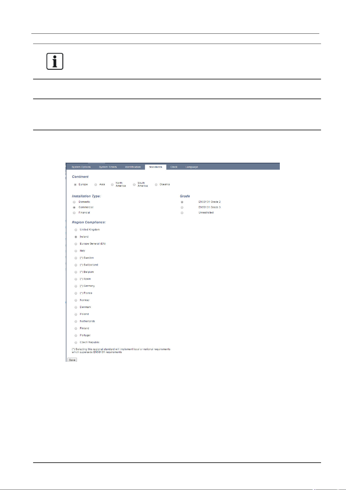
l In the Standards settings page, select Europe under Region to implement EN50131
requirements.
l Select Grade 2 or Grade 3 to implement the grade of EN50131 compliance.
l The Wireless setting Prevent Setting Time must be set to a value greater than 0 and less than
20.
l The Wireless setting Device Lost Time must be set to a value less than 120.
l The X-BUS Settings, Retries, must be set to a value of 10.
l The X-BUS Settings, Comms timer, must be set to a value of 5.
l Select Synchronization Time with Mains under Clock settings to use mains as clock master.
© Vanderbilt 2018 20 A6V10276959-d
12.09.2018
Page 21
SPC4xxx/5xxx/6xxx – Installation & Configuration Manual Directives and standards
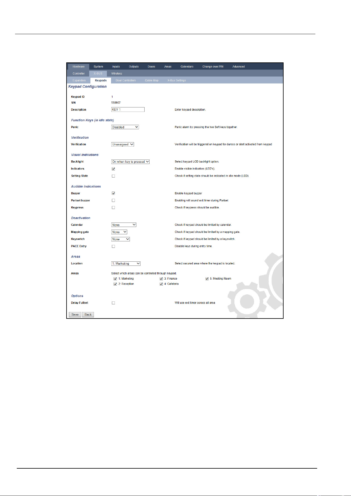
l DO NOT select the attribute Setting State in the Keypad configuration settings for Visual
indications.
Hardware Requirements
l The back tamper kit (SPCY130) must be installed for panels and power supplies for compliance with
EN50131 Grade 3.
l EN50131 Grade 3 compliant components must be installed for EN50131 Grade 3 compliant
systems.
l Either EN50131Grade 2 or 3 compliant components must be installed for EN50131 Grade 2
compliant systems.
l It is not possible to enrol a wireless device with a signal strength lower than 3.
l The recommended ratio of wireless receivers to transmistters is no more than 20 transmitters for
every one receiver.
l Glassbreak must be used with an EN-compliant glassbreak interface.
l To comply with EN50131-3:2009, do not set or unset the system using the SPCE120 (Indicator
Expander) or the SPCE110 (Keyswitch Expander).
© Vanderbilt 2018 21 A6V10276959-d
12.09.2018
Page 22
SPC4xxx/5xxx/6xxx – Installation & Configuration Manual Directivesand standards
The SPCN110 PSTN module and SPCN320 GSM/GPRS module are tested with EN50131
approved Grade 2 and Grade 3 panels and can be used with these approved panels.
3.3 Compliance with EN 50136-1:2012 and EN 50136-2:2014
SPC products listed have been tested according to EN 50136-1:2012 and EN 50136-2:2014.
3.4 Compliance with INCERT Approvals
Software Requirements
Selecting Belgium (*) under Region implements local or national requirements which supercede
EN50131 requirements.
Selecting Grade 2 or Grade 3 selects EN50131 compliance plus any additional INCERT requirements:
l Only an engineer can restore a tamper. For INCERT, this applies across all grades.
This is normally only a requirement for Grade III En50131.
l A tamper on an Inhibited/Isolated zone must be sent to an ARC and displayed to the user.
For INCERT, tampers are processed for isolated zones. On all other standard variations,
tampers are ignored on isolated zones.
l User PIN codes must be defined with more than 4 digits.
© Vanderbilt 2018 22 A6V10276959-d
12.09.2018
Page 23

SPC4xxx/5xxx/6xxx – Installation & Configuration Manual Directives and standards
Hardware Requirements
l The minimum battery capacity for SPC42xx/43xx/52xx/53xx/63xx is 10Ah/12V. If a 10Ah battery is
used, then the battery is biased to the left of the housing and the bottom flap is bent to meet the
battery.
l Fit jumper (J12) on the battery selector for 17/10Ah battery use and remove for 7Ah battery.
l The amount of current from Aux output using a 10Ah battery for SPC42xx/SPC52xx is:
COMMS
NONE (mA) PSTN (mA) GSM (mA) PSTN+GSM (mA)
Standby time
12 h 568 543 438 413
24h 214 189 84 59
30 h 143 118 13 N/A
60h 2 N/A N/A N/A
l The amount of current from Aux output using a 10Ah battery for SPC43xx/SPC53xx/ SPC63xx is:
COMMS
NONE (mA) PSTN (mA) GSM (mA) PSTN+GSM (mA)
Standby time
12 h 538 513 408 383
24 h 184 159 54 29
30 h 113 88 N/A N/A
60 h N/A N/A N/A N/A
3.5 PD 6662:2010 Conformance Guidelines
This document contains all the criteria for the installation, and commissioning and maintenance of the SPC
System to enable it to conform to the PD 6662:2010 Standard.
3.5.1 Product scope
The scope of this document is aimed at the following components of the SPC system:
SPC4320.320-L1 Grade2 Controller
SPC5320.320-L1 Grade2 Controller
SPC5330.320-L1 Grade3 Controller
SPCE652.100Expander, 8Inputs/2Outputs
SPCP332.300 Smart PSU with I/O Expander
SPCP355.300Smart PSU with 8Inputs/2Outputs Expander
SPC5350.320-L1 Grade3 Controller
SPC6330.320-L1 Grade3 Controller
SPC6350.320-L1 Grade3 Controller
SPCP333.300 Smart PSU with I/O Expander
SPCN110.000 PSTN Module
SPCN320.000 GSM Module
SPCK420/421.100 LCD Keypad
SPCE452.100Expander, 8Relay Outputs
© Vanderbilt 2018 23 A6V10276959-d
12.09.2018
Page 24
SPC4xxx/5xxx/6xxx – Installation & Configuration Manual Directivesand standards
3.5.2 Standards overview
Guidelines are provided for the implementation of PD 6662:2010 conformance for an SPC system to
the following relevant standards:
PD 6662:2010
BS 4737-3.1:1977
BS 8243:2010
BS 8473:2006+A1:2008
BS EN 50131-1:2006+A1:2009
BS EN 50136-1-1:1998+A2:2008
BS EN 50136-1-2:1998
BS EN 50136-1-3:1998
BS EN 50136-1-5:2008
BS EN 50136-2-1:1998 +A1:1998
BS EN 50136-2-2:1998
BS EN 50136-2-3:1998
BS EN 50131-3:2009
BS EN 50131-6:2008
DD 263:2010
DD CLC/TS 50131-7:2008
3.5.3 Methods for the completion of setting and unsetting
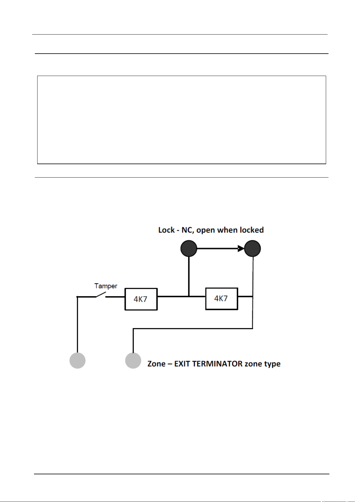
3.5.3.1 Methods of completion of setting (BS 8243:2010 - Clause 6.3)
Completion/Termination of the full setting procedure is achieved by any of the following methods:
a) Shunt lock fitted to the final exit door
A shunt lock must be installed by the installer as follows:
An EXIT TERMINATOR zone type must be configured for SPC.
See Zone types on page385.
b) Push button switch mounted outside the supervised premises
Connect the push button into an SPC zone input as follows:
An EXIT TERMINATOR zone type must be configured for SPC.
See Zone types on page385.
© Vanderbilt 2018 24 A6V10276959-d
12.09.2018
Page 25

SPC4xxx/5xxx/6xxx – Installation & Configuration Manual Directives and standards
c) Protective switch (that is, door contact) fitted to the final exit door of the alarmed premises or
area
Connect the switch to the SPC System as follows:
The contact is fitted to the final exit door and is connected to an ENTRY/EXIT zone with a ‘Final Exit‘
attribute.
See Zone types on page385 and Zone attributes on page390.
A misoperation signal is possible using the alarm abort feature. This is enabled by default.
See Options on page113 (Keypad) and Options on page255 (Browser).
d) Digital key
Not supported by SPC.
e) In conjunction with an ARC
This method of setting is supported by using SPC COM XT or other third party ARC software using EDP
commands.
3.5.3.2 Methods of completion of unsetting (BS 8243:2010 - Clause 6.4)
Unsetting methods are complied with as follows:
6.4.1 For all the unsetting methods in the SPC system there is an audible indication to the user that the
system has been unset successfully. This is in the form of a beep sequence from the CIE.
6.4.2 Prevention of entry to the supervised premises before the intruder alarm system (IAS) is
unset:
a) Unlocking the initial entry door causes the IAS to be unset;
Compliance by SPC if KEYARM zone type is used with the UNSET attribute only. This zone type must
not be used for setting.
b) Unsetting the IAS by the user before entering the supervised premises causes or permits the initial entry
door to be unlocked.
Compliance by SPC by unsetting using an access card reader on an entry reader with the UNSET option,
or an input from a third party access system to a KEYARM zone with an UNSET attribute.
6.4.3 Prevention of entry to the supervised premises before all means of intruder alarm
confirmation have been disabled:
a) Unlocking the initial entry door causes all means of confirmation to be disabled
Operation not permitted by SPC.
b) Disabling all means of confirmation by the user before entering the supervised premises causes or
permits the initial entry door to be unlocked
Operation not permitted by SPC.
6.4.4 Opening the initial entry door disables all means of intruder alarm confirmation
Operation not permitted by SPC.
6.4.5 Completion of unsetting using a digital key
a) Operation of a digital key before entering the supervised premises (for example, via radio)
SPC satisfies this clause when the installer installs a PACE reader (for example, SPCK421) outside the
premises.
b) Operation of a digital key after entering the supervised premises from a location as near as practicable
to the initial entry door.
This functionality is provided by use of a PACE reader (for example, SPCK421) near the entry door of a
premises.
© Vanderbilt 2018 25 A6V10276959-d
12.09.2018
Page 26

SPC4xxx/5xxx/6xxx – Installation & Configuration Manual Directivesand standards
See Zone types on page385 and Zone attributes on page390.
WARNING: Your attention is drawn to the fact that by allowing this method of unsetting, if an
intruder succeeds in forcing the initial entry door, the police will not be called, regardless of the
intruder’s further progress through the premises.
This method of unsetting the intruder alarm system might be unacceptable to your insurers.
6.4.6 Unsetting in conjunction with an alarm receiving centre (ARC)
Compliance by SPC using third party ARC software. Indication external to the building must be
provided by means of a timed buzzer/strobe, etc., that will operate on a system unset for a timed
period, for example, 30 seconds.
See Timers on page117.
3.5.4 Configuration requirements for PD 6662:2010 conformance
Recommendations for the recording of remotely notified alarm conditions (BS 8243:2010 Annex G.1 and G.2)
Alarm conditions can be categorised for analysis in accordance with Annex G if the SPC system is
configured so that the entry timer is less than 30 seconds, and the dialer delay is set to 30 seconds.
See the following sections:
l Areas on page121
l Adding/Editing an area on page273
l Timers on page117
Requirements for systems using dedicated alarm paths (BS EN 50136-1-2, 1998)
The SPC system should be configured to do an automated test call to the ARC.
The SPC system should be configured with a 'Fail to Communicate‘output.
See the following section:
l Adding/Editing an ARC using SIA or CID on page329
Requirements for equipment used in systems with digital communicators using PSTN (BS EN
50136-2-2, 1998)
Fault Output
The SPC system should be configured with a 'Fail to Communicate‘output.
See the following sections:
l Outputs on page153 (Keypad)
l Configuring controller inputs and outputs on page231 (Browser)
l Adding/Editing an ARC using SIA or CID on page329
Retransmission Attempts
Retransmission attempts (Dial Attempts) are configured in this manual:
l Adding/Editing an ARC using SIA or CID on page329
l Editing EDP settings on page339
A minimum of 1 and a maximum of 12 retransmissions are allowed.
Intrusion and hold-up - System design (DD CLC TS 50131-7, 2008)
Setting and unsetting
SPC system is configurable in such a way that the setting is completed by 'Final Exit'.
It is possible to configure the SPC so that a WD (Warning Device) is activated momentarily on setting.
© Vanderbilt 2018 26 A6V10276959-d
12.09.2018
Page 27

SPC4xxx/5xxx/6xxx – Installation & Configuration Manual Directives and standards
See the following sections:
l Timers on page117
l Zone attributes on page390
l Outputs on page153 (Keypad)
l Editing an output on page233 (Browser)
Intrusion and confirmed hold-up alarm (BS8243:2010 Designation of hold-up alarm (HUA) signals
for sequential confirmation)
SPC system is configurable in such a way that the following scenarios, when triggered more than two
minutes apart from any hold-up zone or hold-up device (HD), will report a confirmed hold-up alarm event
(HV for SIA and 129 for CID) to the CIE:
l two hold-up zone activations
l a hold-up zone and a panic zone activation
If a hold-up zone and a tamper zone or a panic zone and a tamper zone activation occurs within the two
minute period, this will also send a confirmed hold-up alarm event.
A confirmed hold-up will not require an engineer restore even if engineer restore is enabled. A confirmed
hold-up event is logged in the system log.
3.5.5 Additional commissioning requirements for PD 6662:2010 conformance
Information to be included in the system design proposal and as-fitted document (BS 8243:2010 Annex F)
l During the installation, configuration and commissioning of an SPC system, the installer must
adhere to the following guidelines as required in the above annex:
l It is recommended that dual paths are used for signalling which are supported in the SPC system
using GSM, PSTN and Ethernet options.
l The SPC system must be installed and configured to provide an effective confirmation facility. Any
exceptions to this should be outlined in the ‘As Fitted’ document.
l Combinations and sequences which contribute to a confirmed alarm should be clearly notified to the
end user.
l The intrusion confirmation time should be clearly notified to the end user.
l Methods of completion of setting and unsetting methods should be clearly described to the end user
as detailed in this document.
l Ensure written arrangements are supplied to the end user in the event of a lock failure.
It is recommended that the enclosed PD 6662:2010 label is affixed in an appropriate position on the
inside of the SPC housing beside the product type label.
3.5.6 Additional information
Transmission Network Requirements – Performance, Availability and Security Levels (BS EN
50136-1-2, 1998 and BS EN 50136-1-5, 2008)
The SPC System has been tested and approved to EN50136-1-1.
SPC levels are classified as follows:
Transmission time D2 as max.
© Vanderbilt 2018 27 A6V10276959-d
12.09.2018
Page 28

SPC4xxx/5xxx/6xxx – Installation & Configuration Manual Directivesand standards
Transmission time, max. values M0 – M4
Reporting time T3 as max.
Availability See ATS levels and attenuation specifications on page394.
Signalling security level Tested to EN50136-1-1 and classified as ‘S0’.
3.6 Compliance with VdS approvals
This installation document encompasses the required product installation information for VdS
approvals.
Vanderbilt
SPC42xx/43xx/53xx/63xx : VdS Approval Nr. G 112104, G112124, and G112128. VdS EN Certificates
EN-ST000142, EN-ST000143, EN-ST000055, EN-ST000056, EN-ST000057, EN-ST000058, ENST000061, EN-ST000062.
Siemens
SPC42xx/43xx/53xx/: VdS Approval Nr. G116035. VdS EN Certificates EN-ST000225, ENST000226, EN-ST000227, EN-ST000228, EN-ST000229, EN-ST000230, EN-ST000231, ENST000232.
This section describes the compliance of this system with VdS approvals.
Configuring software for VdS compliance
To set the system for VdS compliance, do the following:
1. Log on to the panel with the browser.
2. Click Full Engineer.
3. Click Configuration > System > Standards.
4. Select Europe in the Continent section of the page.
5. Select Germany in the Region Compliance section of the page.
6. Select the VDS grade required by your installation type.
Hardware Fault reporting — in Configuration > System > System Options, you must select the
Enabled + Reporting (10s) option from the Watchdog Output Mode drop-down list.
Hardware faults are not reported if the Engineer is logged in to the system.
Hardware
VdS compliance requires the following:
l A G5 housing with Front tamper implemented as a minimum requirement.
l Keypads do not show status information if the system is armed.
l The number of supported zones is as follows:
– 512 zones in ring configuration
– 128 zones per X-Bus in multi-drop (spur) configuration
l The following end of line resistance combinations do not comply with VdS standards:
– 1k, 470 ohm
– 1k, 1k, 6k6 ohm
© Vanderbilt 2018 28 A6V10276959-d
12.09.2018
Page 29

SPC4xxx/5xxx/6xxx – Installation & Configuration Manual Directives and standards
3.7 Compliance with NF and A2P approvals
Address of Certifying Body
CNPP Cert
Pôle Européen de Sécurité - Vernon
Route de la Chapelle Réanville
CD 64 - CS 22265
F-27950 SAINT MARCEL
www.cnpp.com
AFNOR Certification
11 rue François de Pressensé
93571 Saint Denis La Plaine Cedex
www.marque-nf.com
To comply with NF and A2P installation regulations, this housing must be sealed by affixing the
accompanying Tamper Label after installation.
SPC products listed have been tested according to NF324 - H58, with reference to RTC50131-6 and
RTC50131-3 and current EN certifications. See Compliance with EN50131 Approvals on page20.
Product Type Configuration Standard Logo
SPC6350.320 + SPCP355.300
(Cert. 1233700001 + Cert.8033700002)
60h, unmonitored NF Grade
3,
Class 1
SPC5350.320 + SPCP355.300
60h, unmonitored
(Cert. 1233700001 + Cert.8033700002)
SPC6350.320
60h, unmonitored
(Cert. 1233700001)
SPC5350.320
60h, unmonitored
(Cert. 1233700001)
© Vanderbilt 2018 29 A6V10276959-d
12.09.2018
Page 30
SPC4xxx/5xxx/6xxx – Installation & Configuration Manual Directivesand standards
Product Type Configuration Standard Logo
SPC6330.320 + SPCP333.300
(Cert. 1233700001)
SPC5330.320 + SPCP333.300
(Cert. 1232200003)
SPC6330.320
(Cert. 1233700001)
SPC5330.320
(Cert. 1232200003)
SPC5320.320
(Cert. 1232200003)
SPC4320.320
(Cert. 1232200003)
SPCN110.000
SPCN320.000
SPCK420.100
60h, unmonitored NF Grade
3,
Class 1
60h, unmonitored
30h, monitored
30h, monitored
36h, unmonitored NF Grade
2,
Class 1
36h, unmonitored
NF Grade 2
and 3,
Class 1
SPCK620.100
SPCK623.100
SPCE652.100
SPCE452.100
SPCE110.100
SPCE120.100
© Vanderbilt 2018 30 A6V10276959-d
12.09.2018
Page 31

4 Technical Data
This chapter covers:
4.1 SPC4000 31
4.2 SPC5000 33
4.3 SPC6000 37
4.4 SPCP355.300 40
4.1 SPC4000
Programmable areas 4
Max. number of user PINs 100
Remote controls Up to 32
PACE Devices 32
Wireless Panic Alarm Up to 128
Event memory 1000 intrusion events, 1000 access events
Number of on-board zones 8
Max. number of hardwired zones 32
Max. number of wireless zones 32 (take away wired zones)
Max. number of Intrunet wireless
20
detectors per wireless receiver
(recommended)
EOL resistor Dual 4k7 (default), other resistor combinations configurable
Number of on-board relays 1 strobe (30V DC/1A resistive switching current)
Number of on-board open coll. 2 internal/external bell, 3 freely programmable (each max. 400mA resistive
switching current, supplied via auxiliary output)
Firmware V3.x
Door capacity Max. 4 entry doors or 2 entry/exit doors
Number of card reader Max. 4
Radio module l SPC4221: integrated SiWay RF receiver (868MHz)
l SPC4320.220: Optional (SPCW111)
l SPC4320.320: Optional (SPCW110)
Verification 4 verification zones with max. 4 IP-cameras and 4 audio devices.
Video Up to 16 pre/16 post event images (by JPEG resolution 320 x 240, max. 1
frame/sec.)
© Vanderbilt 2018 31 A6V10276959-d
12.09.2018
Page 32

SPC4xxx/5xxx/6xxx – Installation & Configuration Manual Technical Data
Audio Up to 60sec. pre/60sec. post audio recording
Field bus 1) X-BUS on RS-485 (307kb/s)
Number of field devices 2) Max. 11 (4 keypads, 2 door-expanders, 5 input/output expanders)
Connectable field devices l Keypads: SPCK42x, SPCK62x
l Door expanders: SPCA210, SPCP43x
l Expanders with I/O: SPCE65x, SPCE45x, SPCP33x, SPCE110,
SPCE120, SPCV32x
Interfaces l 1 X-BUS (1 spur)
l 1 RS232
l USB (PC connection)
l SPC43xx: Additionally 1 Ethernet (RJ45)
Tamper contact Front spring tamper, 2 auxiliary tamper contact inputs
Power supply Type A (per EN50131-1)
Mains voltage 230V AC, + 10%/ -15%, 50Hz
Mains fuse 250mA T (replaceable part on mains terminal block)
Power consumption SPC42xx: Max. 160mA at 230V AC
SPC43xx: Max. 200mA at 230V AC
Operating current SPC42xx Controller: Max. 160mA at 12V DC
SPC43xx Controller: Max. 200mA at 12V DC
Quiescent current SPC42xx Controller:
Max. 140mA at 12V DC (165mA with PSTN, 270mA with GSM, 295mA with
PSTN and GSM)
SPC43xx Controller:
Max. 170mA at 12V DC (195mA with PSTN, 300mA with GSM, 325mA with
PSTN and GSM)
Output voltage 13–14V DC in normal conditions (mains powered and fully charged battery),
min. 10.5V DC when powered by secondary device (before system shut down
to battery deep discharge protection)
Low voltage trigger 7.5V DC
Overvoltage protection 15.7V DC
Peak to Peak ripple Max. 5% of output voltage
Auxiliary power (nominal) Max. 750mA at 12V DC
Battery type
(Battery not supplied)
SPC422x/4320:
l YUASA NP7-12FR (12V/7Ah) - NF
l PowerSonic PS1270 (12V/7Ah)
l YUASA Yucel Y7-12FR (12V/7Ah)
Battery charger SPC422x/4320: Max. 72h to 80% of battery capacity
© Vanderbilt 2018 32 A6V10276959-d
12.09.2018
Page 33

SPC4xxx/5xxx/6xxx – Installation & Configuration Manual Technical Data
Battery protection Current limited to 1A (fuse protected), deep discharge protection at 10.5V DC
+/- 3%
Software update Local and remote upgrade for controller, peripherals and GSM/PTSN modems.
Calibration No calibration checks required (calibrated at manufacturing)
Serviceable parts No serviceable parts
Operating temperature -10 to +50°C
Relative humidity Max. 90% (non condensing)
Colour RAL 9003 (signal white)
Weight SPC422x/4320: 4.500kg
Dimensions (W x H x D) SPC422x/4320: 264 x 357 x 81mm
Housing SPC4320.320: Small metal housing (1.2mm mild steel)
SPC422x.220: Small housing with metal base (1.2mm mild steel) and plastic lid
Housing can contain up to SPC422x/4320: 1 additional expander (size 150 x 82mm)
IP rating 30
ATS 3
ATP 8
Event Profiles 5
Event Exceptions 10
Command Profiles 5
1) Max. 400m between devices/cable types IYSTY 2 x 2 x Ø 0.6mm (min.), UTP cat5 (solid core) or
Belden 9829.
2) More I/O expanders can be addressed instead of a keypad or door expander, but number of
programmable inputs/outputs cannot exceed specified system limits.
4.2 SPC5000
Programmable areas 16
Max. number of user PINs 500
Remote controls Up to 100
PACE Devices 250
Wireless Panic Alarm Up to 128
Event memory 10,000 intrusion events, 10,000 access events
Number of on-board zones l SPC5320/5330 — 8
l SPC5350 — 16
© Vanderbilt 2018 33 A6V10276959-d
12.09.2018
Page 34

SPC4xxx/5xxx/6xxx – Installation & Configuration Manual Technical Data
Max. number of hardwired
128
zones
Max. number of wireless zones 120 (take away wired zones)
Max. number of Intrunet
20
wireless detectors per wireless
receiver (recommended)
EOL resistor Dual 4k7 (default), other resistor combinations configurable
Relay Outputs l SPC5320/5330 — 1 strobe (30V DC/1A resistive switching current)
l SPC5350 — 4 (single-pole changeover, 30V DC/ maximum 1A resistive
switching current)
Electronic Outputs l SPC5320/5330 — 5 outputs:
– 2 internal/external bells
– 3 programmable. Maximum 400mA resistive switching current per
output, supplied by auxiliary output.
l SPC5350 — 8 outputs. Maximum 400mA resistive switching current per
output
– 5 standard power outputs
– 3 supervised outputs
Firmware V3.x
Door capacity Max. 16 entry doors or 8 entry/exit doors
Number of card reader Max. 16
Radio module Optional (SPCW110)
Verification 16 verification zones with max. 4 IP-cameras and 16 audio devices.
Video Up to 16 pre/16 post event images (by JPEG resolution 320 x 240, max. 1
frame/sec.)
Audio Up to 60sec. pre/60sec. post audio recording
Field bus 1) X-BUS on RS-485 (307kb/s)
Number of field devices 2) Max. 48 (16 keypads, 8 door-expanders, 16 input/output expanders)
Connectable field devices l Keypads: SPCK42x, SPCK62x
l Door expanders: SPCA210, SPCP43x
l Expanders with I/O: SPCE65x, SPCE45x, SPCP33x, SPCP35x,
SPCE110, SPCE120, SPCV32x
Interfaces l 2 X-BUS (2 spurs or 1 loop)
l 2 RS232
l 1 USB (PC connection)
l SPC53xx: Additionally 1 Ethernet (RJ45)
© Vanderbilt 2018 34 A6V10276959-d
12.09.2018
Page 35

SPC4xxx/5xxx/6xxx – Installation & Configuration Manual Technical Data
Tamper contact l SPC5320/5330: Front spring tamper, 2 auxiliary tamper contact inputs
l SPC5350: Front/back tamper switch
Power supply Type A (per EN50131-1)
Mains voltage 230V AC, + 10%/-15%, 50Hz
Mains fuse l SPC5320/5330: 250mA T (replaceable part on mains terminal block)
l SPC5350: 800mA T (replaceable part on mains terminal block)
Power consumption l SPC5320/5330: Max. 200mA at 230V AC
l SPC5350: Max. 500mA at 230V AC
Operating current l SPC5320/5330: Controller: Max. 200mA at 12V DC
l SPC5350: Max. 210mA at 12V DC
Quiescent current SPC53xx Controller: Max. 170mA at 12V DC (195mA with PSTN, 300mA
with GSM, 325mA with PSTN and GSM)
Output voltage 13–14V DC in normal conditions (mains powered and fully charged battery),
min. 10.5V DC when powered by secondary device (before system shut
down to battery deep discharge protection)
Low voltage trigger 11V DC
Overvoltage protection l SPC5320/5330: 15.7V DC
l SPC5350: 15V DC nominal
Peak to Peak ripple Max. 5% of output voltage
Auxiliary power (nominal) l SPC5320/5330: Max. 750mA at 12V DC
l SPC5350: Max. 2200mA at 12V DC (8 separately fused outputs, 300mA
per output)
© Vanderbilt 2018 35 A6V10276959-d
12.09.2018
Page 36

SPC4xxx/5xxx/6xxx – Installation & Configuration Manual Technical Data
Battery type
(Battery not supplied)
SPC5320:
l YUASA NP7-12FR (12V/7Ah) - NF
l PowerSonic PS1270 (12V/7Ah)
l YUASA Yucel Y7-12FR (12V/7Ah)
SPC5330:
l YUASA NP17-12IFR (12V/17Ah) - NF
l YUASA Yucel Y17-12FR (12V/17Ah)
l PowerSonic PS12170 (12V/7Ah)
SPC5350:
l FIAMM FGV22703 (12V/27Ah) - NF
l PowerSonic PS12260FR (12V/26Ah)
l PowerSonic PS12170 (12V/17Ah)
l Alarmcom AB1227-0 (12V/27Ah)
l YUASA NPL24-12IFR (12V/24Ah)
l YUASA Yucel Y17-12IFR (12V/17Ah)
l YUASA Yucel Y24-12FR (12V/24Ah)
Battery charger l SPC5320: Max. 72h,
l SPC5330/5350: Max. 24h to 80% of battery capacity
Battery protection l SPC5320/5330: Current limited to 1A (fuse protected), deep discharge
protection at 10.5V DC +/- 3%
l SPC5350: Current limited to 2A (protected by PTC resettable fuse),
deep discharge protection at 10.5V DC
Software update Local and remote upgrade for controller, peripherals and GSM/PTSN
modems.
Calibration No calibration checks required (calibrated at manufacturing)
Serviceable parts l SPC5320/5330: No serviceable parts
l SPC5350: 8 glass fuses (400mA AT) for 12V DC outputs
Operating temperature -10 to +50°C
Relative humidity Max. 90% (non condensing)
Colour RAL 9003 (signal white)
Weight l SPC5320: 4.500kg
l SPC5330: 6.400kg
l SPC5350: 18.600kg
Dimensions (W x H x D) l SPC5320: 264 x 357 x 81mm
l SPC5330: 326 x 415 x 114mm
l SPC5350: 498 x 664 x 157mm
© Vanderbilt 2018 36 A6V10276959-d
12.09.2018
Page 37

SPC4xxx/5xxx/6xxx – Installation & Configuration Manual Technical Data
Housing l SPC5320: Small metal housing (1.2mm mild steel)
l SPC5330: Hinged metal housing (1.2mm mild steel)
l SPC5350: Metal housing (1.5mm mild steel)
Housing can contain up to l SPC5320: 1 additional expander
l SPC5330: 4 additional expanders (size 150 x 82mm)
l SPC5350: 4 additional expanders (150 x 82mm)
IP/IK Rating 30/06
ATS 5
ATP 15
Event Profiles 10
Event Exceptions 50
Command Profiles 8
1) Max. 400m between devices/cable types IYSTY 2 x 2 x Ø 0.6mm (min.), UTP cat5 (solid core) or
Belden 9829.
2) More I/O expanders can be addressed instead of a keypad or door expander, but number of
programmable inputs/outputs cannot exceed specified system limits.
4.3 SPC6000
Programmable areas 60
Max. number of user PINs 2500
Remote controls Up to 100
PACE Devices 250
Wireless Panic Alarm Up to 128
Event memory 10,000 intrusion events, 10,000 access events
Number of on-board zones l SPC6320/6330 — 8
l SPC6350 — 16
Max. number of hardwired
zones
Max. number of wireless
zones
512
120 (take away wired zones)
Max. number of Intrunet
20
wireless detectors per
wireless receiver
(recommended)
EOL resistor Dual 4k7 (default), other resistor combinations configurable
© Vanderbilt 2018 37 A6V10276959-d
12.09.2018
Page 38

SPC4xxx/5xxx/6xxx – Installation & Configuration Manual Technical Data
Relay Outputs l SPC6320/6330 — 1 strobe (30V DC/1A resistive switching current)
l SPC6350 — 4 (single-pole changeover, 30V DC/ maximum 1A resistive
switching current)
Electronic Outputs l SP6320/6330 — 5 outputs:
– 2 internal/external bells
– 3 programmable. Maximum 400mA resistive switching current per
output, supplied by auxiliary output.
l SPC6350 — 8 outputs. Maximum 400mA resistive switching current per
output
– 5 standard power outputs
– 3 supervised outputs
Firmware V3.x
Door capacity Max. 64 entry doors or 32 entry/exit doors
Number of card reader Max. 64
Radio module Optional (SPCW110)
Verification 32 verification zones with max. 4 IP-cameras and 32 audio devices.
Video Up to 16 pre/16 post event images (by JPEG resolution 320 x 240, max. 1
frame/sec.)
Audio Up to 60sec. pre/60sec. post audio recording
Field bus 1) X-BUS on RS-485 (307kb/s)
Number of field devices 2) Max. 128 (32 keypads, 32 door-expanders, 64 input/output expanders)
Connectable field devices l Keypads: SPCK42x, SPCK62x
l Door expanders: SPCA210, SPCP43x
l Expanders with I/O: SPCE65x, SPCE45x, SPCP33x, SPCP35x,
SPCE110, SPCE120, SPCV32x
Interfaces l 2 X-BUS (2 spurs or 1 loop)
l 2 RS232
l 1 USB (PC connection)
l SPC63xx: Additionally 1 Ethernet (RJ45)
Tamper contact l SPC6330: Front spring tamper, 2 auxiliary tamper contact inputs
l SPC6350: Front/back tamper switch
Power supply Type A (per EN50131-1)
Mains voltage 230V AC, +10%/-15%, 50Hz
Mains fuse l SPC6330: 250mA T (replaceable part on mains terminal block)
l SPC6350: 800mA T (replaceable part on mains terminal block)
© Vanderbilt 2018 38 A6V10276959-d
12.09.2018
Page 39

SPC4xxx/5xxx/6xxx – Installation & Configuration Manual Technical Data
Power consumption l SPC6330: Max. 200mA at 230V AC
l SPC6350: Max. 500mA at 230V AC
Operating current l SPC6330: Max. 200mA at 12V DC
l SPC6350: Max. 210mA at 12V DC
Quiescent current SPC63xx Controller: Max. 170mA at 12V DC (195mA with PSTN, 300mA
with GSM, 325mA with PSTN and GSM)
Output voltage l SPC6330: 13–14V DC in normal conditions (mains powered and fully
charged battery), min. 10.5V DC when powered by secondary device
(before system shut down to battery deep discharge protection)
l SPC6350: 13–14V DC in normal conditions (mains powered and fully
charged battery), min. 10.5V DC when powered by secondary device
(before system shut down to battery deep discharge protection)
Low voltage trigger 11V DC
Overvoltage protection l SPC6330: 15.7V DC
l SPC6350: 15V DC nominal
Peak to Peak ripple Max. 5% of output voltage
Auxiliary power (nominal) l SPC6330: Max. 750mA at 12V DC
l SPC6350: Max. 2200mA at 12V DC (8 separately fused outputs, 300mA
per output)
Battery type
(Battery not supplied)
SPC6330:
l YUASA NP17-12FR (12V/17Ah) - NF
l YUASA Yucel Y17-12IFR (12V/17Ah)
l YUASA Yucel Y24-12FR (12V/24Ah)
l PowerSonic PS12170 (12V/7Ah)
l PowerSonic PS12260 (12V/26Ah)
SPC6350:
l YUASA NP17-12FR(12V/17Ah) - NF
l FIAMM FGV22703 (12V/27Ah) - NF
l YUASA NPL24-12IFR (12V/24Ah)
l Alarmcom AB1227-0 (12V/27Ah)
l PowerSonic PS12260 (12V/26Ah)
Battery charger SPC63xx: Max. 24h to 80% of battery capacity
Battery protection l SPC6330: Current limited to 1A (fuse protected), deep discharge
protection at 10.5V DC +/- 3%
l SPC6350: Current limited to 2A (protected by PTC resettable fuse), deep
discharge protection at 10.5V DC, low voltage indicator at 11V DC
Software update Local and remote upgrade for controller, peripherals and GSM/PTSN modems.
Calibration No calibration checks required (calibrated at manufacturing)
© Vanderbilt 2018 39 A6V10276959-d
12.09.2018
Page 40

SPC4xxx/5xxx/6xxx – Installation & Configuration Manual Technical Data
Serviceable parts l SPC6330: No serviceable parts
l SPC6350: 8 glass fuses (400mA AT) for 12V DC outputs
Operating temperature -10 to +50°C
Relative humidity Max. 90% (non condensing)
Colour RAL 9003 (signal white)
Weight l SPC6330: 6.400kg
l SPC6350: 18.600kg
Dimensions (W x H x D) l SPC6330: 326 x 415 x 114mm
l SPC6350: 498 x 664 x 157mm
Housing l SPC6330: Hinged metal housing (1.2mm mild steel)
l SPC6350: Metal housing (1.5mm mild steel)
Housing can contain up to l SPC6330: 4 additional expanders (size 150 x 82mm)
l SPC6350: 6 additional expanders (150 x 82mm) or 1 additional controller +
4 expanders
IP/IK Rating 30/06
ATS 10
ATP 30
Event Profiles 20
Event Exceptions 100
Command Profiles 10
1) Max. 400 m between devices/cable types IYSTY 2 x 2 x Ø 0.6mm (min.), UTP cat5 (solid core) or
Belden 9829.
2) More I/O expanders can be addressed instead of a keypad or door expander, but number of
programmable inputs/outputs cannot exceed specified system limits.
4.4 SPCP355.300
Number of on-board zones 8
EOL resistor Dual 4k7 (default), other resistor combinations selectable
Relay Outputs 3 (single-pole changeover, 30V DC/max. 1A resistive switching current)
Electronic Outputs 3 supervised (each max. 400mA resistive switching current),
Interfaces X-BUS (in, out, branch)
Mains Voltage 230V AC, +10 to -15%, 50Hz
Operating Current Max. 245mA at 12V DC (all relays activated)
Quiescent Current Max. 195mA at 12V DC
Output voltage 13–14V DC in normal conditions (mains powered and fully charged battery),
© Vanderbilt 2018 40 A6V10276959-d
12.09.2018
Page 41

SPC4xxx/5xxx/6xxx – Installation & Configuration Manual Technical Data
Auxiliary power (nominal) Max. 2360mA at 12V DC (8 separately fused outputs, max. 300mA per output)
Battery type
(Battery not supplied)
l FIAMM FGV22703 (12V/27Ah) - NF
l YUASA NP17-12FR (12V/17Ah)
l YUASA NPL24-12IFR (12V/24Ah)
l Alarmcom AB1227-0 (12V/27Ah)
l PowerSonic PS12170 (12V/17Ah)
l PowerSonic PS12260 (12V/26Ah)
l YUASA Yucel Y17-12IFR (12V/17Ah)
l YUASA Yucel Y24-12FR (12V/24Ah)
Tamper contact Front/back tamper switch
Operating temperature 0 to +40°C
Housing Metal housing (1.5mm mild steel)
Colour RAL 9003 (signal white)
Dimensions 498 x 664 x 157mm
Weight (without batteries) 18.400kg (housing incl. cover), 11.300kg (housing without cover)
IP/IK Rating 30/06
© Vanderbilt 2018 41 A6V10276959-d
12.09.2018
Page 42

5 Introduction
The SPC series controller is a true hybrid controller with 8 on-board wired zones that communicate with
intruder devices.
The flexible design of the controller allows the functional components (PSTN/GSM/RF) to be mixed and
matched, improving the capability of the system. Using this approach, an installer can ensure that an
efficient installation with minimal wiring is achieved.
Overview
Number Description Number Description
1 PSTN 13 Wireless expander
2 GSM 14 PSU
3 Ethernet 15 Loop configuration
4 Wireless Receiver 16 PSTN network
5 AC mains 17 GSM network
6 Battery 12V 18 Broadband router
7 RF 19 Network
8 Wired outputs (6) 20 Central
9 Wired inputs (8) 21 LAN/WLAN
10 Keypads 22 Service desk
11 IO expander 23 Remote user
12 Output Expander 24 Mobile interfaces
© Vanderbilt 2018 42 A6V10276959-d
12.09.2018
Page 43

6 Mounting system equipment
This chapter covers:
6.1 Mounting a G2 housing 43
6.2 Mounting a G3 housing 44
6.3 Mounting a G5 housing 51
6.4 Mounting a keypad 56
6.5 Mounting an expander 56
6.1 Mounting a G2 housing
The SPC G2 housing is supplied with a metallic or plastic cover. The cover is attached to the base of the
housing by 2 securing screws located on the top and bottom of the front cover.
To open the housing, remove both screws with the appropriate screwdriver and lift the cover directly from
the base.
The G2 housing contains the controller PCB (Printed Circuit Board) mounted on 4 support pillars. An
optional input/output module can be mounted directly beneath the controller PCB. A battery with capacity
of 7Ah max. can be accommodated below the controller.
An optional external antenna must be fitted to housings with metallic lid if the wireless functionality is
required. If an antenna is fitted to the unit, it must be enabled in the firmware.
The SPC G2 housing provides 3 screw holes for wall mounting the unit.
To wall mount the housing, remove the cover and locate the initial fixing screw hole at the top of the
housing. Mark the position of this screw hole on the desired location on the wall and drill the initial screw
hole. Screw the unit to the wall and mark the position of the bottom 2 screw hole positions with the unit
vertically aligned.
Screws with a 4–5mm shank, a minimum head diameter of 8mm and a minimum length of 40mm are
recommended for mounting the housing. Additional expansion plugs or fixings may be required depending
on the construction of the wall.
© Vanderbilt 2018 43 A6V10276959-d
12.09.2018
Page 44

SPC4xxx/5xxx/6xxx – Installation & Configuration Manual Mounting system equipment
Standard housing
Number Description
1 Wireless antenna
2 SPC controller
3 Wall mounting screw holes
6.2 Mounting a G3 housing
The SPC G3 housing is supplied with a metallic front cover. The cover is attached to the base of the
housing by hinges and secured with one screw on the right hand side of the front cover.
To open the housing, remove the screws with the appropriate screwdriver and open the front cover.
The G3 housing contains the controller PCB (Printed Circuit Board) mounted on a hinged mounting
bracket. Expanders and PSUs can be mounted on the underside of the hinged mounting bracket and also
on the back wall of the housing underneath the mounting bracket.
© Vanderbilt 2018 44 A6V10276959-d
12.09.2018
Page 45

SPC4xxx/5xxx/6xxx – Installation & Configuration Manual Mounting system equipment
Number Description
1 Expanders/PSU
2 Controller
3 Expanders/PSU
4 Battery
An optional external antenna must be fitted to housings with metallic lid if the wireless functionality is
required. If an antenna is fitted to the unit, it must be enabled in the firmware.
The SPC G3 housing provides 3 screw holes for wall mounting the unit (see item 1 below).
Screws with a 4–5mm shank, a minimum head diameter of 8mm and a minimum length of 40mm are
recommended for mounting the housing. Additional expansion plugs or fixings may be required
depending on the construction of the wall.
© Vanderbilt 2018 45 A6V10276959-d
12.09.2018
Page 46

SPC4xxx/5xxx/6xxx – Installation & Configuration Manual Mounting system equipment
To wall mount the housing:
Open the cover and locate the initial fixing screw hole at the top of the housing.
1.
Mark the position of this screw hole on the desired location on the wall and drill the initial screw hole.
2.
3. Screw the unit to the wall and mark the position of the bottom 2 screw hole positions with the unit
vertically aligned.
Back Tamper Requirements
A back tamper switch may be required by your local approval.
The back tamper switch is delivered with SPC panels in G3 housings or is available as an optional extra
with a mounting kit (SPCY130). EN50131 G3 panels (SPCxx3x.x20) are supplied with a back tamper kit
as standard.
6.2.1 Mounting a Back Tamper Kit
The SPC back tamper kit provides SPC control panels and power supplies with the option of having back
tamper as well as front tamper.
The back tamper kit comprises the following parts:
l Tamper switch
l Leads for connecting the back tamper switch to the controller
l Wall fixing plate
© Vanderbilt 2018 46 A6V10276959-d
12.09.2018
Page 47

SPC4xxx/5xxx/6xxx – Installation & Configuration Manual Mounting system equipment
Mounting the Wall Fixing Plate
1. Mount the SPC in the appropriate position on the wall using all three fixings (see item 1 below).
2. Draw a line around the inside of the back tamper cut out (see item 2 above) to provide a guide for
the wall plate on the fixing wall. Remove the housing from the wall.
3. Place the wall plate (see item 1 below) on the wall centering it precisely around the rectangle
previously drawn (see item 2 below).
4. Ensure all four flanges on the wall plate are flush with the wall.
5. Mark the four fixings on the wall plate.
6. Drill and use suitable screws (max. 4mm) for the wall substrate.
7. Fit the wall plate to the wall.
Fitting the Back Tamper Switch
1. Insert the tamper switch (see item 2 below) into the back of the housing so that the plunger faces
outwards (see item 1 below).
© Vanderbilt 2018 47 A6V10276959-d
12.09.2018
Page 48

SPC4xxx/5xxx/6xxx – Installation & Configuration Manual Mounting system equipment
2. Fit the housing back onto the wall using the three fixings previously removed (see item 2 below).
Visually check to ensure there is a flush finish between the wall plate and the housing metalwork.
© Vanderbilt 2018 48 A6V10276959-d
12.09.2018
Page 49

SPC4xxx/5xxx/6xxx – Installation & Configuration Manual Mounting system equipment
Number Description
1 Housing
2 Wall
3 Wall Fixing Plate
4 Tamper Switch
WARNING: If the wall fixing plate is not accurately aligned then the housing will not sit properly on
its fixings.
Wiring the Back Tamper Switch to the Control Panel
All control panels have spare inputs configured as tamper inputs that are designed for wiring the tamper
switch and do not require any programming.
This tamper switch will be referred to as ‘Aux Tamper 1’ by the system.
© Vanderbilt 2018 49 A6V10276959-d
12.09.2018
Page 50

SPC4xxx/5xxx/6xxx – Installation & Configuration Manual Mounting system equipment
1. Connect NO on the tamper switch to T1 on the controller.
2. Connect COM on the tamper switch to C on the controller. Ensure the T2 jumper is not removed.
3. When the tamper switch is wired, the controller can be commissioned in the normal manner.
6.2.2 Battery installation for EN50131 compliance
For EN50131 compliance the battery needs to be retained within the housing to stop movement. This is
achieved by bending out the flaps in the rear of the Hinged Housing so that the battery is retained.
If a 7Ah battery is used then the battery is biased to the left of the housing and bottom flap is bent to meet
the battery.
If a 17Ah battery is used then the battery is biased to the right of the housing and middle flap is bent to
meet the battery.
The battery flaps should be bent carefully as not to damage the battery. If any signs of a damaged
battery exist or any leakage of the electrolyte then the battery should be discarded as per the current
regulations and a new battery fitted.
© Vanderbilt 2018 50 A6V10276959-d
12.09.2018
Page 51

SPC4xxx/5xxx/6xxx – Installation & Configuration Manual Mounting system equipment
6.3 Mounting a G5 housing
The SPC G5 housing comprises of a metallic base and front cover. The cover is attached to the base of
the housing by 4 securing screws located on the top and bottom of the front cover.
To open the housing, remove all the screws with the appropriate screwdriver and lift the cover directly
from the base.
The G5 housing contains the controller PCB (Printed Circuit Board) and the SPCP355.300 Smart PSU,
both mounted on 4 support pillars. An 8 In/2 Output Expander is mounted on top of the PSU. Four extra
pillars are included to give you the option to mount the 8 In/2 Output Expander below the PSU board in
the G5 housing. Additional expanders can be installed in the housing as shown.
Number Description Number Description
1 Battery 6 Battery temperature leads
2 Battery strap 7 PSU
© Vanderbilt 2018 51 A6V10276959-d
12.09.2018
Page 52

SPC4xxx/5xxx/6xxx – Installation & Configuration Manual Mounting system equipment
Number Description Number Description
3 Fixing tabs 8 Optional expander positions
4 Strap holes 9 Controller
5 Battery leads 10 Antenna
Two batteries, with a maximum capacity of 27Ah, can be accommodated in the battery compartment at
the bottom of the housing.
An optional external antenna must be fitted to a metallic housing if wireless functionality is required.
Knockout holes are available in three positions on the top of the housing where the antenna can be
installed. If an antenna is fitted to the unit, it must be enabled in the firmware.
The SPC G5 housing provides 4 screw holes for wall mounting the unit.
Number Description
1 Corner fixings
2 Tamper cutout
3 Shelf separating battery compartment
4 Telecom socket cutout
6.3.1 Tamper protection
The tamper switch and back tamper bracket are fitted to the housing. The switch is used on its own for
front tamper purposes only or used with the back tamper bracket for both front and back tamper protection.
Either back or front tamper protection is required depending on local approval.
The tamper bracket is held firmly in place with a securing screw. Remember to remove this screw if
commissioning the system for back tamper protection. Do not remove this screw if using front tamper
only.
© Vanderbilt 2018 52 A6V10276959-d
12.09.2018
Page 53

SPC4xxx/5xxx/6xxx – Installation & Configuration Manual Mounting system equipment
6.3.2 Mounting the housing with tamper protection
To mount the housing:
1. Using the supplied mounting template, mark the 4 drill positions for fixing the housing to the wall.
2. Drill and install suitable screws (see enclosed template) into the wall. Leave the screws
protruding 1.5cm from the wall.
3. The G5 housing is pre-configured for front tamper only. To configure the housing for both front
and back tamper, remove the front tamper securing screw (item 1).
The tamper bracket swings to the far right of the orientation slot (item 6).
4. Mount the G5 housing in the appropriate position on the wall and tighten the 4 mounting screws.
Ensure that the housing is flush with the wall surface.
5. Move the tamper bracket to the far left of the orientation slot and tighten the back tamper screw
(item 5) to the wall. The tamper bracket should be perpendicular to the back wall of the housing.
6. Install the lid on the housing to test the tamper switch connection. Lift the lid by approximately
1mm to activate the tamper switch.
Number Description Number Description
1 Front tamper securing screw 5 Back tamper screw
2 Tamper bracket 6 Orientation slot
3 Tamper switch 7 Shelf separating battery compartment
4 Back tamper cutout
WARNING: If the back tamper screw is not secure against the wall, then tamper protection is
compromised. If the housing is removed from the wall or displaced, the back tamper contact needs
to be tested again for proper functionality and re-adjusted if required.
© Vanderbilt 2018 53 A6V10276959-d
12.09.2018
Page 54

SPC4xxx/5xxx/6xxx – Installation & Configuration Manual Mounting system equipment
6.3.2.1 Tamper operation
Tamper switch - normal
Number Description
1 Wall
2 Back tamper screw
3 Back wall of housing
4 Housing lid
5 Tamper switch contact closed
Tamper switch – displaced
Number Description
1 Wall
2 Back tamper screw
3 Back wall of housing
4 Housing lid
5 Tamper switch contact open
If the housing is removed from the wall or displaced, the tamper bracket screw is no longer secure against
the wall, causing the bracket to pivot. This in turn causes the tamper switch to swivel away from the lid
and opens the switch contact.
© Vanderbilt 2018 54 A6V10276959-d
12.09.2018
Page 55

SPC4xxx/5xxx/6xxx – Installation & Configuration Manual Mounting system equipment
WARNING: If the tamper bracket screw is not secure against the wall, then tamper protection is
compromised.
6.3.3 Installing the batteries
If using two batteries in the G5 housing, it is recommended that both batteries should be the same
Ah rating.
Number Description Number Description
1 Battery 6 Battery temperature lead
2 Fixing strap 7 PSU
3 Battery fixing tabs 8 Optional expander positions
4 Strap holes 9 Controller
5 Battery leads 10 Antenna
To install the batteries:
1. Place the batteries into the battery compartment.
2. Press the metal tabs at the top and either side of the batteries in towards the batteries.
3. Secure each battery to the housing using a battery strap. Ensure that the strap is thread through
the battery strap holes at the back of the battery compartment and around the battery, with the
two ends of the strap at the front of the battery.
4. Fasten the two ends of the strap firmly using the Velcro strip. Ensure that the strap is tight
© Vanderbilt 2018 55 A6V10276959-d
12.09.2018
Page 56

SPC4xxx/5xxx/6xxx – Installation & Configuration Manual Mounting system equipment
around the battery.
5. Connect one end of the battery leads to the battery + and - terminals and the other ends to the
corresponding + and - inputs of the PSU.
CAUTION: When installing the battery, always connect the positive (+) lead to
the battery first before connecting the negative (-) lead. When removing the
battery, always remove the negative (-) lead first before removing the positive (+).
6. Connect the loose ends of the attached temperature monitoring leads to the battery temperature
monitoring inputs on the PSU.
6.4 Mounting a keypad
See the corresponding installation instruction.
Installation guides are available at http://www.spcsupportinfo.com/connectspcdata/userdata.
6.5 Mounting an expander
See the corresponding installation instruction.
Installation guides are available at http://www.spcsupportinfo.com/connectspcdata/userdata.
© Vanderbilt 2018 56 A6V10276959-d
12.09.2018
Page 57

7 Smart PSU
This section describes the components and wiring of the Smart PSU.
7.1 SPCP355.300 Smart PSU
The SPCP355.300 Smart PSU is a power supply combined with an 8-input/2-output expander, contained
in a G5 housing. The PSU is backed up by either 2x24Ah, or 2x27Ah batteries, and provides eight power
and four logical outputs
The expander monitors the PSU for overcurrent, fuse failures, AC voltage, communications, and battery
output. The expander is powered by, and receives data from, the PSU via a connector cable. It also
interfaces with the SPC controller over the SPX X-BUS.
Number Description
SPCP355.300 Smart PSU
1 Mains input and fuse block
2 Input transformer
3 AC IN — AC power input
4 MAINS — Mains power LED
5 BATT1 — Battery 1 charge state LED
6 BATT2 — Battery 2 charge state LED
7 FUSE — Fuse fail LED
© Vanderbilt 2018 57 A6V10276959-d
12.09.2018
Page 58

SPC4xxx/5xxx/6xxx – Installation & Configuration Manual Smart PSU
Number Description
8 LIMIT — Current limit LED
9 STATUS — Status LED
10 A2 — 14.5V power output.
l Not backed up by battery
l Protected by PTC resettable fuse, rated at 300mA (Item 23 in image above)
11 A1 — Connects to the power input (+/-) on the SPC5350/6350.
12 COMM1 — Expander 4-pin interface. Connects to item 32, power and data connection, in image above,
with a straight-through cable.
13 Clock Reference — Connects to Clock Reference on SPC5350/6350.
14 T1, T2 — Tamper switch inputs. Connect these to the Front/Back tamper switch.
See Mounting the housing with tamper protection on page53.
15 Front back tamper switch. See Mounting the housing with tamper protection on page53.
16 NO/NC — Configurable NO/NC logical relay output. See Wiring the Outputs on page64 for more
information.
17 Glass fuses — 400mA T fuses for outputs 1-8.
18 OP 6–8 and SW 6–8 — Combined power outputs (OP) and logical outputs (SW).
Standard 12V DC power outputs combined with configurable, open-drain, logical outputs (4k7 EoL
supervised/unsupervised).
19 OP 1–5 — Standard 12V DC power outputs.
See warning note below this table for more information.
20 BTE2 — Battery 2 temperature monitoring input.
21 BATT1 and BATT2 — Battery 1 and 2 connectors.
22 BTE1 — Battery 1 temperature monitoring input.
23 PTC fuses — Fuses rated at 300mA. Protecting the A1 and A2 outputs.
For more information see System Recovery on page67.
24 PTC fuse — Fuse rated at 5A. Protects the AC power input (item 3 in image above).
For more information see System Recovery on page67.
25 PSU Kickstart Switch — For more information see System Recovery on page67.
Expander
26 NO/NC — Logical relay outputs. The expander provides two configurable NO/NC logical relay outputs.
For more information, see Wiring the Inputs on page63.
27 I 1–8 — Inputs. The expander has 8 on-board inputs which can be configured as intruder alarm zones on
the SPC system.
For more information, see Wiring the Inputs on page63.
© Vanderbilt 2018 58 A6V10276959-d
12.09.2018
Page 59

SPC4xxx/5xxx/6xxx – Installation & Configuration Manual Smart PSU
Number Description
28 Auxiliary power supply 12V — Do not use.
Expander is powered through COMM1 on the SPCP355.300 Smart PSU.
29 X-BUS Input power — Do not use.
Expander is powered through COMM1 on the SPCP355.300 Smart PSU.
30 X-BUS Interface — The communications bus connects expanders on the SPC system.
31 Termination Jumper — This jumper is always fitted, by default.
For more information, see Wiring the X-BUS Interface on page62.
32 PSU 4-pin interface — Connects to COMM1 on the SPCP355.300 Smart PSU (item 12 in image
above), power and data connector, with a straight-through cable.
33 Front tamper switch — Not used. The Front/Back tamper connected to T1 and T2 of the SPCP355.300
Smart PSU is the only tamper required by this installation.
34 JP1 — Front tamper bypass must be fitted.
35 Buzzer — Activated to locate the expander. See Locate on page125 for more information.
36 JP6 — Back tamper bypass. Must be fitted.
37 Manual addressing switches — Enable manual setting of the ID of the expander.
38 X-BUS Status LED — Indicates the X-BUS status, when the system is in Full Engineer mode, as
follows:
l Slow flash (every 1.5 seconds) — X-BUS communications status is OK.
l Quick flash (every 0.2 seconds) — Indicates one of the following:
– Indicates the last-in-line expander for spur configurations.
– Indicates a communications problem between two expanders. If two adjacent expanders are
flashing quickly, the problem exists between those two expanders.
39 LED — Not used.
40 PSU Status LED.
WARNING: The combined maximum load current drawn from all 12V DC outputs (OP 1–8) plus
COMM1, should not exceed 2.4A. Each individual output, and output A2, should not exceed
300mA. If the device current requires more than 300mA, it is recommended to parallel the outputs.
Adding extra expanders
If adding extra expanders to the G5 housing, you must ensure the front and back tampers are
deactivated by fitting the appropriate jumpers. In a G5 housing, the front and back tamper is handled by
the housing itself and the SPCP355.300 Smart PSU.
7.1.1 Supervised Outputs
The SPCP355.300 Smart PSU supports three, open-drain, logical outputs, which can be supervised for
tamper detection. Output tamper detection is enabled by configuration. Output tamper detection is
enabled by connecting a 4k7 EoL resistor in parallel with the load device, such as an external bell. A
© Vanderbilt 2018 59 A6V10276959-d
12.09.2018
Page 60

SPC4xxx/5xxx/6xxx – Installation & Configuration Manual Smart PSU
power diode (1N4001 for example, or similar) is also required, if not already present in the external device.
Number Description
1 Standard 12V Power output
2 Configurable, supervised, 12V DC logical switched output.
7.1.2 Batteries
This section covers:
l Installing Batteries on the facing page
l Testing Battery Voltage on page62
l Deep Discharge Protection on page62
l Battery Stand-By Times on page62
© Vanderbilt 2018 60 A6V10276959-d
12.09.2018
Page 61

SPC4xxx/5xxx/6xxx – Installation & Configuration Manual Smart PSU
7.1.2.1 Installing Batteries
This section describes the battery installation for the SPCP355.300 Smart PSU and G5 Housing.
Number Description
1 Battery
2 Battery strap
3 Fixing holes
4 Strap holes
5 Battery leads
6 Battery temperature leads
7 PSU/Expander
8 Mounting positions for additional expanders.
© Vanderbilt 2018 61 A6V10276959-d
12.09.2018
Page 62

SPC4xxx/5xxx/6xxx – Installation & Configuration Manual Smart PSU
It is recommended that two batteries are used. These batteries must be of the same type and
capacity.
1. Install the batteries in the battery compartment.
2. Secure each battery using the battery straps provided, ensuring the strap is threaded through the
battery strap holes at the back of the battery and around the battery.
3. Secure the two ends of the battery strap at the front of the battery, ensuring the battery strap is
firmly tightened.
4. Connect the leads from the SPCP355.300 Smart PSU to the batteries in the following order:
- Connect the positive (red) wire first.
- Connect the negative (black) wire second.
DANGER: When removing the battery leads, always disconnect the negative (black) lead before
disconnecting the positive (red) lead.
7.1.2.2 Testing Battery Voltage
The SPCP355.300 Smart PSU performs a load test on each battery by placing a load resistor across the
battery terminals and measuring the resultant voltage. This battery test is performed every five seconds.
7.1.2.3 Deep Discharge Protection
If mains power to the SPCP355.300 Smart PSU fails for a prolonged period, each battery supplies power
to the PSU 12V DC power outputs for a finite time. The batteries eventually discharge. To prevent a
battery discharging beyond recovery, the SPCP355.300 Smart PSU disconnects the battery if the
measured voltage drops below 10.5V DC. The battery can then be recharged after the mains power is
restored.
7.1.2.4 Battery Stand-By Times
See Calculating the battery power requirements on page370 for the battery stand-by information.
7.1.3 Wiring the X-BUS Interface
The X-BUS interface connects expanders and keypads to the SPC controller. The X-BUS can be wired in
a number of different configurations, depending on the installation requirements.
The following table lists the cable types and distances recommended:
Maximum cable length=(numberof expanders and keypads in the system) x (maximum cable
distance for each cable type)
Cable Type Distance
CQR Standard Alarm Cable 200m
UTP Cat-5 Solid core 400m
Belden 9829 400m
© Vanderbilt 2018 62 A6V10276959-d
12.09.2018
Page 63

SPC4xxx/5xxx/6xxx – Installation & Configuration Manual Smart PSU
Cable Type Distance
IYSTY 2x2x0.6(min) 400m
The following diagram shows an example of wiring the X-BUS:
Number Description
1 SPCP355.300 Smart PSU outputs
2 SPC Controller
3 SPCP355.300 Input/Output expander
4 Next expander
5 Next expander
7.1.3.1 Wiring the Inputs
The expander has 8 on-board zone inputs which can be configured as one of the following:
l No End of Line
l Single End of Line
l Dual End of Line
l Anti-Masking PIR
Default Configuration
The following diagram shows the default configuration, Double EOL 4k7:
Number Description
1 Input 1
2 COM
© Vanderbilt 2018 63 A6V10276959-d
12.09.2018
Page 64

SPC4xxx/5xxx/6xxx – Installation & Configuration Manual Smart PSU
Number Description
3 Tamper
4 Alarm
5 4k7
6 EOL 4k7
Anti-Masking PIR
The following diagram shows the Anti-Masking PIR configuration:
Number Description
1 Input 2
2 COM
3 Tamper
4 Alarm
5 4k7
6 Detector Fault
7 2K2
8 EOL 4k7
7.1.3.2 Wiring the Outputs
The expander and PSU relay logical outputs can be assigned to any of the SPC system outputs. The relay
outputs can switch a rated voltage of 30V DC at 1A (non-inductive load).
When the relay is activated, the Common terminal connection (COM) is switched from the Normally
Closed (NC) to the Normally open (NO) terminal.
© Vanderbilt 2018 64 A6V10276959-d
12.09.2018
Page 65

SPC4xxx/5xxx/6xxx – Installation & Configuration Manual Smart PSU
The following diagram shows the wiring of an active, high output:
Number Description
1 Normally Open terminal
2 Common terminal connection (COM)
3 Normally Closed terminal (NC)
7.1.4 Compliance with NF and A2P approvals
Address of Certifying Body
CNPP Cert
Pôle Européen de Sécurité - Vernon
Route de la Chapelle Réanville
CD 64 - CS 22265
F-27950 SAINT MARCEL
www.cnpp.com
AFNOR Certification
11 rue François de Pressensé
93571 Saint Denis La Plaine Cedex
www.marque-nf.com
© Vanderbilt 2018 65 A6V10276959-d
12.09.2018
Page 66

SPC4xxx/5xxx/6xxx – Installation & Configuration Manual Smart PSU
To comply with NF and A2P installation regulations, this housing must be sealed by affixing the
accompanying Tamper Label after installation.
SPC products listed have been tested according to NF324 - H58, with reference to RTC50131-6 and
RTC50131-3 and current EN certifications, see Compliance with EN50131 Approvals on page20.
Product Type Configuration Standard Logo
SPC6350.320 + SPCP355.300
60h, unmonitored NF Grade 3,
(Cert. 1233700001 + Cert.8033700002)
SPC5350.320 + SPCP355.300
60h, unmonitored
(Cert. 1233700001 + Cert.8033700002)
SPC6330.320 + SPCP333.300
60h, unmonitored NF Grade 3,
(Cert. 1233700001)
SPC5330.320 + SPCP333.300
60h, unmonitored
(Cert. 1232200003)
7.1.5 PSU LED Status
The following table lists the Smart PSU LED status information:
LED MAINS
Class 1
Class 1
BATT 1
and 2
FUSE LIMIT STATUS
COLOUR Green Green Red Red Green
Condition
Normal On On Off Off On
Mains OK, battery charging On Flash On
Mains Fail, Battery OK Off On On
Mains OK, battery faulty or not present On Off On
Mains OK, battery faulty, not present, or in deep discharge
All LEDs Off.
protection mode
Fuse Fail On On
Total Load Current exceeded On On
PSU switcher failure Off Off Off Off Flash
© Vanderbilt 2018 66 A6V10276959-d
12.09.2018
Page 67

SPC4xxx/5xxx/6xxx – Installation & Configuration Manual Smart PSU
7.1.6 System Recovery
Mains and Battery Failure
In the event of both mains and battery power failure, the PSU kickstart switch (item 25 in
SPCP355.300 Smart PSU on page57) enables the system to be restarted if only battery power is
reinstated. To kickstart the system, do the following:
Prerequisites
o
Mains power has failed
o
Battery power has failed
o
New batteries are available
1. Attach the battery leads.
2. Press and hold the PSU Kickstart button.
All LEDs flash.
3. Hold the PSU Kickstart button until the LEDs stop flashing.
4. Release the PSU Kickstart button.
PTC Fuse Reset
In the event of one of the PTC fuses resetting, you must manually disconnect then reconnect the mains
and battery connections.
© Vanderbilt 2018 67 A6V10276959-d
12.09.2018
Page 68

8 Controller hardware
This section describes the controller hardware.
See also
Powering expanders from the auxiliary power terminals on page369
Wiring the X-BUS interface on page75
Wiring an internal sounder on page89
Wiring the zone inputs on page85
Controller status LEDs on page368
8.1 Controller Hardware 42xx/43xx/53xx/63xx
This section describes the controller for the SPC42xx, 43xx, 53 xx and 63xx models. The SPC5350 and
6350 are described in Controller Hardware SPC5350 and 6350 on page70.
The SPC controller provides 8 on-board wired zones and optional wireless zones.
Number Name Description
1 Optional
wireless
module
© Vanderbilt 2018 68 A6V10276959-d
The controller PCB can be factory fitted with a wireless module for use with wireless
(868MHz) sensors.
12.09.2018
Page 69

SPC4xxx/5xxx/6xxx – Installation & Configuration Manual Controller hardware
Number Name Description
2 SPC status
LEDs
3 AC power
input
4 Reset
button
5 Earth
connection
terminal
These 7 LEDs display the status of various system parameters as described in Controller
status LEDs on page368.
A/C Mains Input:
The mains AC input voltage is applied to this 2-pin connection via a transformer
contained in the SPC housing. The earth lead from the mains supply is wired to a
connection point on the metal housing.
Clock Reference*:
A clock reference signal can also be applied to this 2-pin connector to maintain accurate
system time.
l To reset the controller:
– Press this switch once.
l To reset the programming settings to default and reboot the controller:
– Hold down the button until you are asked if a factory reset is desired.
– Select YES to reset to factory defaults.
Warning: Defaulting the controller to factory settings deletes all configuration files,
including backups, stored on the controller. All isolates and inhibits are also deleted. It is
recommended you backup your configuration to a PC before defaulting the controller.
Note: This feature is not available if engineer lockout is enabled.
This terminal is not required and should not be connected.
6 Auxiliary
12V output
7 X-BUS
interface
8 On-board
outputs
9 Relay
output
10 Internal
bell/external
bell
The SPC controller provides an auxiliary 12V DC output that can be used to supply power
to expanders and devices such as latches, bells, etc. See Powering expanders from the
auxiliary power terminals on page369. The maximum deliverable current is 750mA.
Note: The amount of current drawn is subject to the amount of time to be held up under
battery conditions.
This is the SPC communications bus used to network expanders together on the system.
See Wiring the X-BUS interface on page75. SPC4000 only has 1 X-BUS interface.
Outputs OP4, OP5, and OP6 are 12V open collector resistive outputs that share a 400mA
current rating with the auxiliary 12V output. If the outputs are not connected to the 12V of
the controller and are powered from an external power source the 0V of the power source
needs to be connected to the controller 0V and the external power source cannot exceed
12V.
The SPC controller provides a 1A, single-pole, changeover relay that can be used to drive
the strobe output on the external bell.
Internal and external bell outputs (INT+, INT-, EXT+, EXT-) are resistive outputs with a
400mA current rating. The BHO (Bell Hold Off), TR (Tamper Return), and EXT outputs
are used to connect an external bell to the controller. The INT+ and INT- terminals are
used to connect to internal devices such as an internal sounder. See Wiring an internal
sounder on page89.
© Vanderbilt 2018 69 A6V10276959-d
12.09.2018
Page 70

SPC4xxx/5xxx/6xxx – Installation & Configuration Manual Controller hardware
Number Name Description
11 Zone inputs The controller provides 8 on-board zone inputs that can be monitored using a variety of
supervision configurations. These configurations can be programmed from system
programming. The default configuration is Dual End of Line (DEOL) using resistor values
of 4k7. See Wiring the zone inputs on page85.
12 Tamper
terminals
The controller provides 2 additional tamper input terminals that can be connected to
auxiliary tamper devices to provide increased tamper protection. These terminals should
be shorted when not in use.
13 Serial port 2
terminal
block
Serial port 2 terminal block (TX, RX, GND) may be used to interface to an external
modem or PC terminal program. Serial port 2 shares a communications channel with the
back-up modem. If a back-up modem is installed, ensure that no devices are connected
to this serial port.
14
The 2 Ethernet LEDs indicate the status of the Ethernet connection. The left LED
indicates data activity on the Ethernet port; the right LED indicates the Ethernet link is
Ethernet
active.
connectivity
LEDs
15
The Ethernet interface provides for the connection of a PC to the controller for the
purposes of programming the system.
Ethernet
interface
16 USB
This USB interface is used to access browser programming or a terminal program.
interface
17 Serial port 2 This RS232 serial port may be used to interface to an external modem or PC terminal
program. Serial port 2 shares a communications channel with the back-up modem. If a
back-up modem is installed, ensure no devices are connected to this serial port.
18 Serial port 1 This RS232 serial port may be used to interface to an X10 protocol device.
19 Optional
plug-in
modules
A primary (left slot) and back-up (right slot) module can be connected to the controller.
These modules can be GSM or PSTN modems offering increased communication
functionality. The back-up modem should not be connected if serial port 2 interface is
connected to an external modem or other device.
20 Front
tamper
21 Battery
selector
This on-board front tamper (switch and switch) provides the housing tamper protection.
Note: The front tamper is not used in the G5 housing.
J12: Fit jumper for 17Ah battery use and remove for 7Ah battery.
Please Note: This selector is only available on 2.3 revision controller PCB.
(Not applicable for SPC5350 and SPC5360 panels.)
22 Auxiliary
12V input from battery or PSU**.
power input
* Default setup for SPC5350 and SPC5360 panels
** PSU only applies to SPC5350 and SPC6350 panels.
8.2 Controller Hardware SPC5350 and 6350
This section describes the SPC5350 and SPC6350.
© Vanderbilt 2018 70 A6V10276959-d
12.09.2018
Page 71

SPC4xxx/5xxx/6xxx – Installation & Configuration Manual Controller hardware
The expander that is connected to the power supply within the G5 is set to ID1 by default. This setting
should not be changed.
Number Name Description
1 Optional
wireless
The controller PCB can be factory fitted with a wireless module for use with wireless
(868MHz) sensors.
module
2 SPC status
LEDs
3 Clock
Reference
These 7 LEDs display the status of various system parameters as described in
Controller status LEDs on page368.
A clock reference signal can also be applied to this 2-pin connector to maintain accurate
system time.
Connect to Clock Reference CN17 on SPCP355.300 Smart PSU.
© Vanderbilt 2018 71 A6V10276959-d
12.09.2018
Page 72

SPC4xxx/5xxx/6xxx – Installation & Configuration Manual Controller hardware
Number Name Description
4 Reset
button
5 Earth
connection
terminal
6 X-BUS
interface
l To reset the controller:
– Press this switch once.
l To reset the programming settings to default and reboot the controller:
– Hold down the button until you are asked if a factory reset is desired.
– Select YES to reset to factory defaults.
Warning: Defaulting the controller to factory settings deletes all configuration files,
including backups, stored on the controller. All isolates and inhibits are also deleted. It is
recommended you backup your configuration to a PC before defaulting the controller.
Note: This feature is not available if engineer lockout is enabled.
This terminal is not required and should not be connected.
This is the SPC communications bus used to network expanders together on the
system. See Wiring the X-BUS interface on page75.
Terminals 1B and 1A must be connected to SPCP355.300 I/O Expander terminals 2B
and 2A, respectively
Terminals 2A and 2B must be connected to terminals 2A and 2B, respectively, of the
next expander on the X-BUS.
7 On-board
outputs
Outputs OP4, OP5, and OP6 are 12V open collector resistive outputs with a 300mA
current rating.
The OP4 load must be connected to the SPCP355.300 Smart PSU.
8 Relay
output
9 Bell Hold-
Off (BHO)
The SPC controller provides a 1A, single-pole, changeover relay that can be used to drive
the strobe output on the external bell.
The BHO (Bell Hold Off) and TR (Tamper Return) (and EXT output) are used to connect
an external bell to the controller. See Wiring an internal sounder on page89.
and Tamper
Return (TR)
10 Internal Bell
(negative)
11 External
Bell
The INT- terminal is used to connect to internal devices such as an internal sounder. The
power for the internal sounder must be connected to the SPCP355.300 Smart PSU.
The Ext- terminal is used to connect to external devices such as an external bell. The
power for the external sounder must be connected to the SPCP355.300 Smart PSU.
(negative)
12 Do not use. Do not use.
13 Zone inputs The controller provides 8 on-board zone inputs that can be monitored using a variety of
supervision configurations. These configurations can be programmed from system
programming. The default configuration is Dual End of Line (DEOL) using resistor values
of 4k7. See Wiring the zone inputs on page85.
14 Tamper
terminals
The controller provides 2 additional tamper input terminals that can be connected to
auxiliary tamper devices to provide increased tamper protection. These terminals should
be shorted when not in use.
© Vanderbilt 2018 72 A6V10276959-d
12.09.2018
Page 73

SPC4xxx/5xxx/6xxx – Installation & Configuration Manual Controller hardware
Number Name Description
15 Serial port 2
terminal
block
Serial port 2 terminal block (TX, RX, GND) may be used to interface to an external
modem or PC terminal program. Serial port 2 shares a communications channel with the
back-up modem. If a back-up modem is installed, ensure that no devices are connected
to this serial port.
16 Ethernet
connectivity
LEDs
17 Ethernet
interface
18 USB
The 2 Ethernet LEDs indicate the status of the Ethernet connection. The left LED
indicates data activity on the Ethernet port; the right LED indicates the Ethernet link is
active.
The Ethernet interface provides for the connection of a PC to the controller for the
purposes of programming the system.
This USB interface is used to access browser programming or a terminal program.
interface
19 Serial port 2 This RS232 serial port may be used to interface to an external modem or PC terminal
program. Serial port 2 shares a communications channel with the back-up modem. If a
back-up modem is installed, ensure no devices are connected to this serial port.
20 Serial port 1 This RS232 serial port may be used to interface to an X10 protocol device.
21 Optional
plug-in
modules
A primary (left slot) and back-up (right slot) module can be connected to the controller.
These modules can be GSM or PSTN modems offering increased communication
functionality. The back-up modem should not be connected if serial port 2 interface is
connected to an external modem or other device.
22 Real-time
clock
battery
23 Auxiliary
power input
See also
Powering expanders from the auxiliary power terminals on page369
Battery for real-time clock (RTC).
12V input from A1 on SPCP355.300 Smart PSU.
© Vanderbilt 2018 73 A6V10276959-d
12.09.2018
Page 74

9 Door Expander
The two door expander can handle up to two doors and two card readers. Configuration of the operation
mode is done via the two door I/Os. Each of the two door I/Os is responsible for the functionality of two
inputs and one output of the door controller. A specific door number can be assigned to a door I/O, which
gives the inputs and output predefined functionality. If no door number is assigned to neither of the door
I/Os (option “Zones” is selected), the inputs and outputs of the door controller can be used like inputs and
outputs on the control panel. Thus, no access functionality is available on this two door controller.
If a door number is assigned only to the first door I/O of the two door controller, the first reader is used as
entry reader for this door. If a second reader is available, it is used as exit reader for the configured door.
Two inputs and one output have predefined functionality and two inputs and one output can be configured
by the user. Additionally, the door position sensor input of the first door can be used as intrusion zone but
only with limited functionality.
If a door number is assigned to each of the two door I/Os, the two doors are handled independently. The
first card reader is used as entry reader for the first door and the second card reader is used as entry reader
for the second door. All inputs and outputs have predefined functionality. The door position sensor inputs of
the two doors can additionally be used as intrusion zones but only with limited functionality.
See Supported card readers and card formats on page394 for details of currently supported card readers
and card formats.
Each free zone number can be assigned to the zones. But the assignment is not fixed. If number 9
was assigned to a zone, the zone and an input expander with the address 1 is connected to the X-Bus
(which is using the zone numbers 9–16).The assigned zone from the two door controller will be moved
to the next free zone number. Configuration will be adapted accordingly.
© Vanderbilt 2018 74 A6V10276959-d
12.09.2018
Page 75

10 Wiring the system
This chapter covers:
10.1 Wiring the X-BUS interface 75
10.2 Wiring of branch expander 83
10.3 Wiring the system ground 84
10.4 Wiring the relay output 84
10.5 Wiring the zone inputs 85
10.6 Wiring an external SAB bell 88
10.7 Wiring an internal sounder 89
10.8 Wiring Glassbreak 89
10.9 Installing plug-in modules 90
10.1 Wiring the X-BUS interface
The X-BUS interface provides for the connection of expanders to the controller. The X-BUS can be wired in
a number of different configurations depending on the installation requirements. The X-BUS interface baud
rate is 307kb.
NOTICE: The X-BUS is an RS-485 bus with a baud rate of 307kb. The full performance is only
supported in loop (see Loop configuration on the next page) and spur (see Spur configuration on
page77) wiring configuration (best signal quality due to daisy chain of isolated sections with 1
transmitter/1 receiver and balanced terminating resistors on each end).
The performance in star or multi-drop configuration wiring (see Star and multi-drop configuration on
page78) is limited due to non-optimal conditions of the RS-485 bus specification (reduced signal
quality due to multiple receivers/transmitters in parallel with unbalanced terminating resistors).
NOTICE: It is strongly recommended to use loop (see Loop configuration on the next page) or spur
(see Spur configuration on page77) configuration.
The table below shows the maximum distances between controller/expander or expander/expander for all
cable types in loop and spur configuration.
Cable Type Distance
CQR standard alarm cable 200 m
UTP Category: 5 (solid core) 400 m
Belden 9829 400 m
IYSTY 2 x 2 x 0.6 (min) 400 m
Each device has 4 terminals (1A, 1B, 2A, 2B) for connection to expanders via the X-BUS cable. The
controller initiates a detection procedure on power up to determine the number of expanders connected on
the system and the topology in which they are connected.
© Vanderbilt 2018 75 A6V10276959-d
12.09.2018
Page 76

SPC4xxx/5xxx/6xxx – Installation & Configuration Manual Wiring the system
Wiring expander
Number Description
1 Previous expander
2 Next expander
3 SPC controller
Most expanders are equipped with additional terminals 3A/3B and 4A/4B for branch expander wiring. See
Wiring of branch expander on page83 for instructions on branch expander wiring.
10.1.1 Loop configuration
NOTICE: The SPC42xx/43xx doesn’t support loop configuration (only 1 X-BUS port).
NOTICE: All expanders/keypads are fitted with a termination jumper by default. In loop configuration
it’s imperative to have these jumpers fitted.
© Vanderbilt 2018 76 A6V10276959-d
12.09.2018
Page 77

SPC4xxx/5xxx/6xxx – Installation & Configuration Manual Wiring the system
The loop (or ring) cabling method offers the highest security by providing fault tolerant communications
on the X-BUS. All keypads and expanders are supervised and in case of a X-BUS fault or break, the
system continues to operate and all detectors are monitored. This is achieved by connecting 1A, 1B on
the controller to 2A, 2B on the first keypad or expander. The wiring continues with connection 1A, 1B to
2A, 2B on the next expander etc. to the last keypad or expander. The last connection is 1A, 1B of the
last expander to 2A, 2B of the controller. See wiring configuration in the figure below.
Number Description
1 Controller
2-4 Expanders
10.1.2 Spur configuration
NOTICE: SPC52xx/53xx/63xx supports 2 spurs (2 X-BUS ports).
SPC42xx/43xx supports 1 spur (1 X-BUS port).
NOTICE: All expanders/keypads are fitted with a termination jumper by default. In spur
configuration it is imperative to have these jumpers fitted.
The spur (or open loop) cabling method offers a high level of fault tolerance and may be more
convenient on certain installations. In the case of a X-BUS fault or break, all expanders and detectors
up to the fault continue to be supervised.
In this configuration, the SPC controller uses a single the X-BUS port (1A/1B or 2A/2B) to support a
group of expanders. See wiring configuration in the figure below. The last expander in an open loop
configuration is not wired back to the controller and can be identified by the fast LED flashing light (one
flash every 0.2 seconds approx) when in Full Engineer programming.
In automatic mode, the expander numbering commences at the expander nearest to the controller and
ends with the expander connected farthest from the controller. For example, if 6 expanders are
connected in an open loop configuration, then the nearest expander on the X-BUS connection is
expander 1, the second nearest expander is 2, etc., ending with the expander wired farthest from the
controller, which is expander 6.
© Vanderbilt 2018 77 A6V10276959-d
12.09.2018
Page 78

SPC4xxx/5xxx/6xxx – Installation & Configuration Manual Wiring the system
All expanders/keypads are fitted with termination jumpers, as default, allowing termination on all the
devices. This is imperative for the spur (chain) configuration, as the jumper acts as a resisting terminator
cancelling echoes on the line.
Within the loop wiring configuration all expanders/keypads are fitted with a jumper, as default, allowing
termination on the device.
Spur configuration
Number Description
1 Controller
2-4 Expanders
10.1.3 Star and multi-drop configuration
NOTICE:See Examples of correct wiring on page81, Examples of incorrect wiring on page82 and
Shielding on page83 before starting the installation.
The star and multi-drop cabling methods enables takeover of existing wirings with four-core cables in small
buildings (typically homes) with low electrical noise environment. These wiring methods are limited to the
specifications below:
SPC42xx/SPC43xx SPC52xx/SPC53xx/SPC63xx
Max. expanders/keypads 8 16 (8 per X-BUS port)
Total cable length 200 m 200 m
NOTICE: The performance in star or multi-drop configuration wiring is limited due to non-optimal
conditions of the RS-485 bus specification (reduced signal quality due to multiple
receivers/transmitters in parallel with unbalanced terminating resistors).
© Vanderbilt 2018 78 A6V10276959-d
12.09.2018
Page 79

SPC4xxx/5xxx/6xxx – Installation & Configuration Manual Wiring the system
Star configuration
NOTICE: All expanders/keypads are fitted with a termination jumper by default. In star
configuration it’s imperative to remove these jumpers.
A star configuration is established when multiple expanders are wired back to the same X-BUS port on
the SPC controller. Depending on controller type 2 ports may exist (1A/1B, 2A/2B), however only one
port (1A/1B) is to be used on each keypad or expander.
In the case of a X-BUS break the single will be disconnected, all other expanders and detectors
continue to be supervised. A short in the cable renders all expanders disabled.
Star configuration
Star configuration 2
© Vanderbilt 2018 79 A6V10276959-d
12.09.2018
Page 80

SPC4xxx/5xxx/6xxx – Installation & Configuration Manual Wiring the system
Number Description
1 SPC Controller
2-4 Expanders
Multi-drop configuration
NOTICE: All expanders/keypads are fitted with a termination jumper by default. In multi-drop
configuration it’s imperative to remove these jumpers with exception of last keypad or expander.
The multi-drop configuration varies in that each expander uses the same communication channel as it
wires onto the next expander, with all expanders using the same input channel. See multi-drop
configuration in the second figure.
In the case of a X-BUS break, all expanders and detectors up to the fault continues to be supervised. A
short in the cable renders all expanders disabled.
Multi-drop configuration
Multi-drop configuration 2
Number Description
1 SPC controller
2-4 Expanders
© Vanderbilt 2018 80 A6V10276959-d
12.09.2018
Page 81

SPC4xxx/5xxx/6xxx – Installation & Configuration Manual Wiring the system
10.1.3.1 Examples of correct wiring
Star wiring
Multi-drop wiring
© Vanderbilt 2018 81 A6V10276959-d
12.09.2018
Page 82

SPC4xxx/5xxx/6xxx – Installation & Configuration Manual Wiring the system
Mixed wiring
10.1.3.2 Examples of incorrect wiring
NOTICE:A mix of star and multi-drop configuration is only allowed if the star point is at the controller
X-BUS port. In this case, all expanders/keypads must be wired in multi-drop configuration without any
other star points in the wiring.
Not allowed wiring with a second star point
© Vanderbilt 2018 82 A6V10276959-d
12.09.2018
Page 83

SPC4xxx/5xxx/6xxx – Installation & Configuration Manual Wiring the system
NOTICE:If the mix of star and multi-drop configuration is not properly wired the reduced signal
quality may lead to slow reaction time of connected devices (for example, keypad operation) or
even loss of communication to devices. If such behavior is observed a wiring in loop OR star
configuration is strongly recommended.
10.1.4 Shielding
The shielding terminals (SHLD) should only be used for cables types with shielding (for example,
Belden 9829). If shielding is required (that is, sites with high electric field interference): connect the
cable shield to the SHLD terminals on the controller and all networked expanders. If the shield
needs to be connected to earth then a cable needs to be connected from the SHLD terminal on the
controller to the chassis earth stud. Do NOT earth the SHLD terminal on any of the expanders.
NOTICE: For star and multi-drop wiring
It is not recommended to use shielded cables due to disadvantageous electrical characteristics
(higher capacitance) in star and multi-drop wiring configuration. However, if shielding is required
(that is, sites with high electric field interference) a new wiring in proper spur or loop configuration
with appropriate installation cable configuration has to be done.
10.1.5 Cable Map
Identification and numbering order for expanders and keypads differ depending on automatic or manual
addressing of the expanders. For information on manual and automatic configuration, see X-BUS on
page123.
For a system with manual addressing, expanders and keypads have a separate numbering sequence
and are defined by the engineer manually. That is, expanders are numbered 01, 02, 03, etc. as desired.
Using same numbers, keypads may be numbered as desired.
In the manual configuration, the system automatically allocates zones to each expander. For this
reason, devices with no zones, such as 8 output expanders should be addressed last.
For a system with automatic addressing, expanders and keypads belong to the same numbering group
and are assigned by the controller. That is, expanders and keypads are together numbered 01, 02, 03,
in the order that they are detected relative to the location of the controller.
10.2 Wiring of branch expander
The wiring of the X-BUS interface with 8 terminals 1A/1B to 4A/4B provides for the connection of an
additional branch expander.
If the branch is not used then the terminals 1A/1B are used to connect to the next expander/keypad.
Terminals 3A/3B and 4A/4B are then not used.
The following modules have branch expander wiring capability (additional terminals 3A/B and 4A/B):
l 8 Input/2 Output Expander
l 8 Output Expander
l PSU Expander
l Wireless Expander
l 2-door Expander
© Vanderbilt 2018 83 A6V10276959-d
12.09.2018
Page 84

SPC4xxx/5xxx/6xxx – Installation & Configuration Manual Wiring the system
Wiring of a branch expander
Number Description
1 Previous expander
2 Expander connected to branch
3 Next expander
4 Expander with branch
10.3 Wiring the system ground
0V of Smart PSU's, Keypads and Expanders must be connected to the SPC controller 0V (System GND).
10.4 Wiring the relay output
The SPC controller has one on-board 1A single pole changeover relay that can be assigned to any of the
SPC system outputs. This relay output can switch a rated voltage of 30V DC (non-inductive load).
When the relay is activated the common terminal connection (COM) is switched from the Normally Closed
terminal (NC) to the Normally Open terminal (NO).
© Vanderbilt 2018 84 A6V10276959-d
12.09.2018
Page 85

SPC4xxx/5xxx/6xxx – Installation & Configuration Manual Wiring the system
Standard wiring
NO Normally open terminal
COM Common terminal connection
NC Normally closed terminal
10.5 Wiring the zone inputs
The SPC controller has 8 on-board zone inputs. By default these inputs are monitored using end of line
supervision. The installer can choose from any of the following configurations when wiring the inputs:
l No End of Line (NEOL)
l Single End of Line (SEOL)
l Dual End of Line (DEOL)
l Anti-masking PIR
Default configuration (DEOL 4k7)
© Vanderbilt 2018 85 A6V10276959-d
12.09.2018
Page 86

SPC4xxx/5xxx/6xxx – Installation & Configuration Manual Wiring the system
Number Description
1 Tamper
2 Alarm
3 EOL 4k7
4 EOL 4k7
Anti-Masking PIR configuration
Number Description
1 Tamper
2 Alarm
3 EOL 4k7
4 Fault
5 EOL 2K2
6 EOL 4k7
The following table shows the resistance ranges associated with each configuration.
Single EOLs
Quiescent Alarm
EOL Type
Min Nom Max Min Nom Max
NONE 0Ω
(-100%)
150Ω 300Ω
(+100%)
300Ω
(+100%)
N/A Infinite
SINGLE_1K 700Ω
(-30%)
SINGLE_1K5 1.1kΩ
(-27%)
SINGLE_2K2 1.6kΩ
(-28%)
SINGLE_4K7 3.1kΩ
(-22%)
© Vanderbilt 2018 86 A6V10276959-d
1kΩ 1.3kΩ
(+30%)
1.5kΩ 2.1kΩ
(+40%)
2.2kΩ 2.9kΩ
(+32%)
4.7kΩ 6.3kΩ
(+24%)
23kΩ N/A Infinite
23kΩ N/A Infinite
23kΩ N/A Infinite
23kΩ N/A Infinite
12.09.2018
Page 87

SPC4xxx/5xxx/6xxx – Installation & Configuration Manual Wiring the system
Quiescent Alarm
EOL Type
Min Nom Max Min Nom Max
SINGLE_10K 7kΩ
(-30%)
SINGLE_12K 8.5kΩ
(-30%)
Dual EOLs with PIR Masking and Fault
EOL Type
Mask_1K_1K_6K8
(1K / 1K / 6K8)
Mask_1K_1K_2K2
(1K / 1K / 2K2)
Mask_4K7_4K7_2K2
(4K7 / 4K7 / 2K2)
EOL Type
10kΩ 13kΩ
23kΩ N/A Infinite
(+30%)
12kΩ 15.5kΩ
23kΩ N/A Infinite
(+30%)
Quiescent Alarm
Min Nom Max Min Nom Max
700Ω
(-30%)
700Ω
(-30%)
3.9kΩ
(-18%)
1kΩ 1.3kΩ
(+30%)
1kΩ 1.3kΩ
(+30%)
4.7kΩ 5.6kΩ
(+20%)
1.5kΩ
(-25%)
1.5kΩ
(-25%)
8.4kΩ
(-11%)
2kΩ 2.5kΩ
(+25%)
2kΩ 2.6kΩ
(+30%)
9.4kΩ 10.3kΩ
(+10%)
Fault Masking
Min Nom Max Min Nom Max
Mask_1K_1K_6K8 2700Ω
(-69%)
Mask_1K_1K_2K2 2.8k
(-13%)
Mask_4K7_4K7_2K2 6k
(-14%)
Dual EOLs
EOL Type
Min Nom Max Min Nom Max
DUAL_1K0_470 400Ω
(-20%)
DUAL_1K0_1K0 700Ω
(-30%)
DUAL_1k0_2k2 1.6kΩ
(-28%)
DUAL_1k5_2k2 1.6kΩ
(-28%)
8.8kΩ 12.6kΩ
- - -
(+20%)
3.2k 3.6k
(+13%)
6.9k 7.8k
(+14%)
3.8k
(-10%)
10.8k
(-7%)
4.2k 4.8k
11.6k 12.6k
Quiescent Alarm
470Ω 700kΩ
(+40%)
1kΩ 1.3kΩ
(+30%)
2.2kΩ 2.9kΩ
(+32%)
2.2kΩ 2.9kΩ
(+32%)
1.1kΩ
(-27%)
1.5kΩ
(-25%)
2.3kΩ
(-29%)
2.7kΩ
(-28%)
1.5kΩ 2kΩ
2kΩ 2.6kΩ
3.2kΩ 4.2kΩ
3.7kΩ 4.8kΩ
(+15)
(+9%)
(+34%)
(+30%)
(+32%)
(+30%)
© Vanderbilt 2018 87 A6V10276959-d
12.09.2018
Page 88

SPC4xxx/5xxx/6xxx – Installation & Configuration Manual Wiring the system
Quiescent Alarm
EOL Type
Min Nom Max Min Nom Max
DUAL_2K2_2K2 1.6kΩ
(-28%)
DUAL_2k2_4k7 4.1kΩ
(-13%)
DUAL_2K7_8K2 7.2 kΩ
(-13%)
DUAL_3K0_3K0 2.1kΩ
(-30%)
DUAL_3K3_3K3 2.3kΩ
(-26%)
DUAL_3K9_8K2 7.0 kΩ
(-15%)
DUAL_4K7_2K2 1.6kΩ
(-28%)
DUAL_4K7_4K7 3.3kΩ
(-30%)
DUAL_5K6_5K6 4.0kΩ
(-26%)
2.2kΩ 2.9kΩ
(+32%)
4.7kΩ 5.4kΩ
(+15%)
8.2kΩ 9.2kΩ
(+13%)
3.0kΩ 3.9kΩ
(+30%)
3.3kΩ 4.3kΩ
(+31%)
8.2kΩ 9.5kΩ
(+16%)
2.2KΩ 2.9kΩ
(+32%)
4.7kΩ 6.1kΩ
(+30%)
5.6kΩ 7.2kΩ
(+29%)
3.4kΩ
(-23%)
6kΩ
(-14%)
9.9kΩ
(-10%)
4.5kΩ
(-25%)
4.9kΩ
(-26%)
10.5kΩ
(-14%)
5kΩ
(-28%)
7kΩ
(-26%)
8.3kΩ
(-26%)
4.4kΩ 5.6kΩ
(+28%)
6.9kΩ 7.9kΩ
(+15%)
10.9kΩ 11.9kΩ
(+10%)
6kΩ 7.5kΩ
(+25%)
6.6kΩ 8.3kΩ
(+26%)
12.1kΩ 13.8kΩ
(+15%)
6.9kΩ 8.8kΩ
(+28%)
9.4kΩ 11.9kΩ
(+27%)
11.2kΩ 14.1kΩ
(+26%)
DUAL_6K8_4K7 3.3kΩ
4.7kΩ 6.1kΩ
(-30%)
DUAL_2k2_10K 9.2kΩ
10kΩ 10.8kΩ
(-8%)
DUAL_10k_10k 7.5kΩ
10kΩ 12.5kΩ
(-25%)
For all EOL types, a resistance below 300Ω is considered a short. If the resistance is not within the
thresholds stated, this is treated as a disconnection.
10.6 Wiring an external SAB bell
On an external bell to the SPC controller board the relay output is wired to the strobe input with Bell Hold
Off (BHO) and Tamper Return (TR) connected to their respective inputs on the external bell interface.
A resistor (2K2) is pre-fitted on the controller board between the BHO and TR terminals. When wiring an
external bell, connect this resistor in series from the TR terminal on the controller to the TR terminal on the
external bell interface.
(+30%)
(+8%)
(+25%)
8.1kΩ
(-30%)
11.3 kΩ
(-8%)
17kΩ
(-15%)
11.5kΩ 14.9kΩ
(+30%)
12.2kΩ 13.2kΩ
(+9%)
20kΩ 23kΩ
(+15%)
© Vanderbilt 2018 88 A6V10276959-d
12.09.2018
Page 89

SPC4xxx/5xxx/6xxx – Installation & Configuration Manual Wiring the system
External bell wiring
Label Description
A Strobe +
B Strobe –
C Hold off
D Tamper return
E Bell -
F Bell +
10.7 Wiring an internal sounder
To wire an internal sounder to the SPC controller connect the IN+ and IN– terminals directly to the 12V
sounder input.
Internal sounder wiring (12V)
IN– IN– (SPC controller)
IN+ IN+ (SPC controller)
10.8 Wiring Glassbreak
SPC supports the RI S 10 D-RS-LED glassbreak interface in combination with GB2001 glassbreak
detectors.
© Vanderbilt 2018 89 A6V10276959-d
12.09.2018
Page 90

SPC4xxx/5xxx/6xxx – Installation & Configuration Manual Wiring the system
The following diagram shows how the glassbreak interface is wired to the SPC controller for power, or to
an 8-in/2-out expander:
For information on wiring the glassbreak interface to a zone, see the product-specific documentation.
For information on wiring the glassbreak sensors to the glassbreak interface, see the product-specific
documentation.
10.9 Installing plug-in modules
2 modems (PSTN or GSM) may be installed on the controller board to increase functionality. The picture
below shows the 2 slots available for each modem, the primary (left) slot and the back-up (right) slot.
If both modem slots are available, always install the plug-in module in the primary slot; the system always
attempts to make PSTN or GSM calls on a modem installed on the primary slot before attempting to use
the back-up slot.
WARNING: Modems are not plug and play. You must log on to the panel as Full Engineer, then power
the controller board down before installing, removing or moving modems from one position to the
other. After completing the modem task, reconnect the system to the power supply and log on to the
controller as Full Engineer again. Configure and save the configuration. Failure to follow this process
results in a CRC error.
© Vanderbilt 2018 90 A6V10276959-d
12.09.2018
Page 91

SPC4xxx/5xxx/6xxx – Installation & Configuration Manual Wiring the system
Plug-in modules
Number Description
1 Wireless receiver slot
2 Primary modem slot
3 Back-up modem slot
For installation details, see the corresponding Installation Instruction.
Installation guides are available at http://www.spcsupportinfo.com/connectspcdata/userdata.
© Vanderbilt 2018 91 A6V10276959-d
12.09.2018
Page 92

11 Powering up the SPC controller
The SPC controller has two power sources, the mains supply and the integral standby battery. A qualified
electrician should undertake connection to the mains and the mains supply should be connected from a
spur that can be isolated. See Wiring of mains cable to the controller on page383 for full details of
conductor sizes/fuse ratings, etc.
The SPC should be powered from the mains first and then the internal standby battery. For compliance to
EN only one battery should be fitted of the appropriate capacity.
11.1 Powering from battery only
It is recommended that when powering a system from battery only, the battery should be in a fully charged
state (>13.0V). The system will not power up when using a battery with less than 12V and no mains is
applied.
NOTICE: The battery will continue to power the system until deep discharge level (10.5V to 10.8V)
has been detected. The time duration that the system will hold up on battery will depend on the
external loading and Ah rating of the battery.
© Vanderbilt 2018 92 A6V10276959-d
12.09.2018
Page 93

12 Keypad user interface
The following keypad models are available:
l SPCK420/421 — referred to throughout this document as the LCD Keypad
l SPCK620/623 — referred to throughout this document as the Comfort Keypad
12.1 SPCK420/421
This section covers:
12.1.1 About the LCDkeypad 93
12.1.2 Using the LCD keypad interface 95
12.1.3 Data entry on the LCD keypad 98
12.1.1 About the LCDkeypad
The LCD keypad is a wall-mounted interface that allows:
l Engineers to program the system through the Engineer Programming menus (password protected)
and to set/unset the system; a user can control the system on a day-to-day basis.
l Users to enter User Programming menus (password protected), and to perform operational
procedures (set/unset) on the system. (See the SPCK420/421 User Manual for more details of user
programming.)
The LCD keypad unit includes an integral front tamper switch and has a 2 line x 16 character display. It
features an easy-to-use navigation key to assist in locating required programming options, and has 2
context sensitive soft keys (left and right) for selecting the required menu or program setting. 3 LEDs on
the keypad provide an indication of AC power, system alerts, and communications status.
The LCD keypad may be factory fitted with a Portable ACE (PACE) proximity device reader (see
Overview of keypad types on page381).
© Vanderbilt 2018 93 A6V10276959-d
12.09.2018
Page 94

SPC4xxx/5xxx/6xxx – Installation & Configuration Manual Keypad user interface
LCD keypad
Number Name Description
1 LCD display The keypad display (2 lines x 16 characters) shows all alert and warning messages and
provides a visual interface for programming the system (engineer programming only).
The display can be adjusted for contrast and under which conditions the backlight
comes on.
2 Alphanumeric
keys
Alphanumeric keypad allow for both text and numeric data entry during programming.
Alphabetic characters are selected by applying the appropriate number of key presses.
To switch between upper and lower case characters, press the hash (#) key. To enter a
numeric digit, hold down the appropriate key for 2 seconds.
3 Leverage
access tabs
The leverage access tabs provide access to the keypad back assembly clips. Users
can unhinge these clips from the front assembly by inserting a 5mm screwdriver into the
recesses and pushing gently.
4 Back
assembly
This screw secures the front and back assemblies on the keypad. This screw must be
removed to open the keypad.
securing
screw
5 LED status
indicators
The LED status indicators provide information on the current status of the system as
detailed in the table below.
6 Soft function
keys
© Vanderbilt 2018 94 A6V10276959-d
The left and right soft function keys are context sensitive keys to navigate through
menus/programming.
12.09.2018
Page 95

SPC4xxx/5xxx/6xxx – Installation & Configuration Manual Keypad user interface
Number Name Description
7 Proximity
device
receiver area
8 Multi-
functional
navigation
Key
LED Status
AC
mains
(Green)
System
alert
(Yellow)
Indicates the presence or failure of the mains supply
FLASHING: AC mains fault detected
STEADY: AC mains OK
Indicates a system alert
FLASHING: System alert detected; display indicates the location and nature of alert. If the
system is SET, then NO indication is given of system alerts
OFF: No alert detected; If a keypad is assigned to more than one area, LED does not indicate an
alert condition if any of those areas is SET
If the keypad has been fitted with a proximity device receiver (see Overview of keypad
types on page381), users should present the Portable ACE Fob to within 1 cm of this
area to SET/UNSET the system.
The multi-functional navigation key in combination with the keypad display provides an
interface for programming the system.
X-BUS
Status
(Red)
Indicates the status of the X-BUS communications when in FULL ENGINEER programming
Flashes regularly: (once every 1.5 seconds approx) indicates communications status is OK
Flashes quickly: (once every 0.25 seconds approx) indicates the keypad is the last expander on
the X-BUS
If the keypad is being installed for the first time and power is supplied to it before a connection to
the controller X-BUS interface is made, the LED remains in the ON state
12.1.2 Using the LCD keypad interface
Keypad display
© Vanderbilt 2018 95 A6V10276959-d
12.09.2018
Page 96

SPC4xxx/5xxx/6xxx – Installation & Configuration Manual Keypad user interface
Number Name Description
1 RIGHT
SOFT KEY
This key is used to select the option presented on the right side of the bottom line display.
Possible values are:
l SELECT to select the option displayed on the top line
l ENTER to enter the data displayed on the top line
l NEXT to view the next alert after the one displayed on the top line
l CLEAR to clear the alert displayed on the top line
l SAVE to save a setting
2 OK The OK button acts as a SELECT key for the menu option displayed on the top line and
also as an ENTER/SAVE key for data displayed on the top line.
3 In Programming mode, the right arrow key advances the user through the menus in the
same way as pressing the SELECT option (right soft key).
In data entry mode, press this key to move the cursor one position to the right.
4 In Programming mode, the down arrow key moves the user to the next programming
option in the same menu level. Continually press this key to scroll through all
programming options available on the current menu level.
In alphanumeric mode, press this key over an upper case character to change the
character to lower case.
When alerts are displayed, the down arrow key moves the user to the next alert message
in the order of priority. (See Prioritization of display messages on the facing page.)
5 In Programming mode, the left arrow key returns the user to the previous menu level.
Pressing this key when in the top menu level exits the user from programming.
In data entry mode, press this key to move the cursor one position to the left.
6 In Programming mode, the up arrow key moves the user to a previous programming option
in the same menu level. Continually press this key to scroll through all programming
options available on the current menu level.
In Alphanumeric mode, press this key over a lower case character to change the
character to upper case.
7 LEFT
SOFT KEY
8 BOTTOM
LINE OF
DISPLAY
9 TOP LINE
OF
DISPLAY
This key is used to select the option presented on the left side of the bottom line display.
Possible values are:
l EXIT to exit programming
l BACK to return to previous menu
In the IDLE state, this line is blank.
In Programming mode, this line displays options available to the user. These options align
over the left and right soft keys for selection as required.
In the IDLE state, displays the current date and time. In Programming mode, this line
displays one of the following:
l The programming feature to be selected
l The current setting of the selected feature
l The nature of the current alert during an alert condition. (See Prioritization of display
messages on the facing page.)
© Vanderbilt 2018 96 A6V10276959-d
12.09.2018
Page 97

SPC4xxx/5xxx/6xxx – Installation & Configuration Manual Keypad user interface
Prioritization of display messages
Trouble messages and alerts are displayed on the keypad in the following order:
l Zone
– Alarms
– Tamper
– Trouble
l Area Alerts
– Fail to set
– Entry time out
– Code tamper
l System Alerts
– Mains
– Battery
– PSU fault
– Aux fault
– External bell fuse
– Internal bell fuse
– Bell tamper
– Housing tamper
– Aux tamper 1
– Aux tamper 2
– Wireless jamming
– Modem 1 fault
– Modem 1 line
– Modem 2 fault
– Modem 2 line
– Fail to communicate
– User panic
– XBUS cable fault
– XBUS communications fault
– XBUS mains fault
– XBUS battery fault
– XBUS power supply fault
– XBUS fuse fault
– XBUS tamper fault
– XBUS antenna fault
– XBUS wireless jamming
– XBUS panic
– XBUS fire
© Vanderbilt 2018 97 A6V10276959-d
12.09.2018
Page 98

SPC4xxx/5xxx/6xxx – Installation & Configuration Manual Keypad user interface
– XBUS medical
– XBUS Power supply link
– XBUS output tamper
– XBUS Low voltage
– Engineer restore Required
– Autoarm
l System information
– Soaked zones
– Open zones
– Area state
– Low battery (sensor)
– Sensor lost
– WPA* low battery
– WPA* lost
– WPA* test overdue
– Camera offline
– Fob low battery
– Xbus over current
– Installer name
– Installer phone
– Engineer enable
– Manufacture enable
– Reboot
– Hardware fault
– Aux over current
– Battery low
– Ethernet link
– System name
* A WPA is compatible with SiWay RF Kit (SPCW110, 111, 112, 114 ) only.
12.1.3 Data entry on the LCD keypad
Entering data and navigating the menus on the LCD keypad is facilitated through the use of the
programming interface. The use of the interface for each type of operation is detailed below.
Entering numeric values
In Numeric Entry mode, only the numeric digits (0–9) can be entered.
l To move the position of the cursor one character to the left and right respectively, press the left and
right arrow keys.
l To exit from the feature without saving, press the BACK menu key.
l To save the programmed setting press ENTER or OK.
© Vanderbilt 2018 98 A6V10276959-d
12.09.2018
Page 99

SPC4xxx/5xxx/6xxx – Installation & Configuration Manual Keypad user interface
Entering text
In Text Entry mode, both alphabetic characters (A–Z) and numeric digits (0–9) can be entered.
l To enter an alphabetic character, press the relevant key the required number of times.
l To enter a language specific special character (ä, ü, ö…) press button 1 to cycle through the
special characters.
l To enter a space + special characters (+, -./[]…) press button 0.
l To enter a digit, hold the relevant key down for 2 seconds and release.
l To move the position of the cursor one character to the left and right respectively, press the left
and right arrow keys.
l To exit from the feature without saving, press BACK.
l To save the programmed setting press ENTER or OK.
l To change the case of an alphabetic character, press the up/down arrow keys when the
character is highlighted by the cursor.
l To toggle between upper and lower case for all subsequent characters, press the hash (#) key.
l To delete character to the left of the cursor, press the star key(*).
Selecting a programming option
In navigation mode, the Engineer/User selects one of a number of pre-defined programming options
from a list.
l To scroll through the list of options available for selection, press the up and down arrow keys.
l To exit from the feature without saving, press BACK.
l To save the selected option, press SAVE or OK.
12.2 SPCK620/623
This section covers:
12.2.1 About the Comfort keypad 99
12.2.2 LED description 103
12.2.3 Viewing mode description 103
12.2.4 Function keys in idle state 104
12.2.1 About the Comfort keypad
The Comfort keypad is a wall-mounted interface that allows:
l Engineers to program the system through the Engineer Programming menus (password
protected) and to set/unset the system; a user can control the system on a day-to-day basis.
l Users to enter User Programming menus (password protected), and to perform operational
procedures (set/unset) on the system. (See the SPC620/623 User Manual for more details of
user programming)
The SPCK620 is equipped with soft keys and large graphical LCD for easy operation. The functionality
can be enhanced with key switch expander SPCE110 or indication expander SPCE120.
The SPCK623 is equipped with a proximity card reader (125 kHz EM 4102) for easy user access, soft
keys, large graphical LCD and voice annunciation support. The functionality can be enhanced with key
switch expander SPCE110 or indication expander SPCE120.
© Vanderbilt 2018 99 A6V10276959-d
12.09.2018
Page 100

SPC4xxx/5xxx/6xxx – Installation & Configuration Manual Keypad user interface
Number Name Description
1 LED status
indicators
The LED status indicators provide information on the current status of the system as
detailed in LED description on page103.
2 LCD display The keypad display shows all alert and warning messages and provides a visual
interface for programming the system (engineer programming only). (See Prioritization
of display messages on the facing page.) The display can be configured under which
conditions the backlight comes on.
3 Soft function
Context sensitive keys to navigate through menus/programming.
keys
4 Enter key Confirm display or input.
5 Back menu
key
6 Proximity
device
Go back in the menu.
Reset buzzers, siren and alarms in the memory.
Only SPCK 623: If the keypad has been fitted with a proximity device receiver, users
should present the Portable ACE Fob to within 1 cm of this area.
receiver area
7 Alphanumeric
keys
Alphanumeric keypad allow for both text and numeric data entry during programming.
Alphabetic characters are selected by applying the appropriate number of key presses.
To switch between upper and lower case characters, press the hash (#) key. To enter a
numeric digit, hold down the appropriate key for 2 seconds.
© Vanderbilt 2018 100 A6V10276959-d
12.09.2018
 Loading...