

Page 1
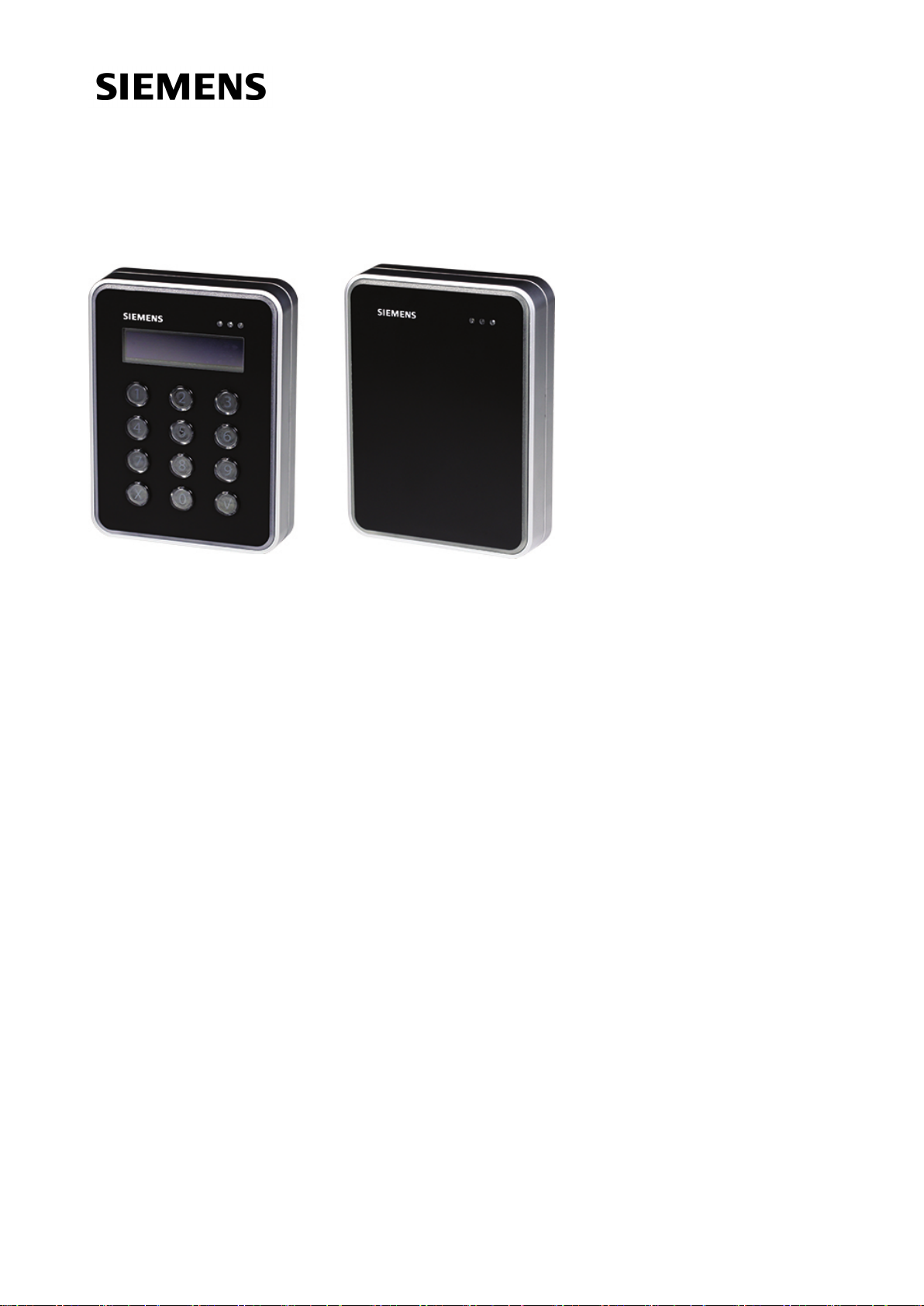
AR40S-MF AR10S-MF
AR10S-MF AR40S-MF
Installation and Mounting
Version 9.0
Siemens Switzerland Ltd
Page 2

Data and design subject to change without notice. / Supply subject to availability.
© 2017 Copyright bySiemens Switzerland Ltd
We reserve all rights in this document and inthe subjectthereof. Byacceptance of the document the recipient acknowledges these rights and
undertakes not to publish the document nor the subject thereof in fullor in part, nor to make them availableto any third party without our prior
express written authorization, nor to use it for anypurpose other than for which it was delivered to him.
Document nr: A-100010-9
Page 3

Content
Content 3
1 Introduction 4
2 Technical data 5
3 Safety regulations 6
3.1 Standards and guidelines 6
3.2 FCC statements 6
4 Reader components 7
5 Mounting and connecting 9
5.1 Surface mounted reader 10
5.2 Surface mounted reader with cables fed from outside 11
5.3 Back box mounted reader 13
5.4 Back box mounted reader with adapter plate 14
5.5 Connecting the cables 15
5.6 Disassembling the reader 17
6 Default settings 18
7 Connecting card reader to SiPass integrated 19
7.1 Setting the card reader address 19
8 Disposal 21
Page 4

1 Introduction
1 Introduction
The AR10S-MF and AR40S-MF are executively designed card readers for modern
security. The encryption*) is conducted via a protocol which ensures a high level of
security, providing that the card reader and system are set to the secure mode.
When the secure mode is activated, the communication from neither the reader nor
the system they are connected to can be extracted. They are made of hardwearing
materials and will endure most weather conditions. The readers are easy to mount
and connect, and can be mounted on a flat surface or partly inside a back box. They
can be cleaned with most kinds of domestic detergents. Both readers have a
multicolour light frame. The AR40S-MF has a keypad and a high contrast display.
*) Only valid for SiPass integrated MP2.65 – or later
4
Siemens Switzerland Ltd
2017-07-14
Page 5
2 Technical data
2 Technical data
AR10S-MF Mifare card reader
standard
AR40S-MF Mifare card reader
standard with keypad and display
Protocol OSDP OSDP
Interface to controller RS485 RS485
Operating voltage 8.5 – 30.0 VDC 8.5 – 30.0 VDC
Power consumption DC 12V 43mA Peak 168mA
DC 24V 26mA Peak 100mA
DC 12V 60mA Peak 220mA
DC 24V 40mA Peak 125mA
Tamper protection Yes Yes
Card technology Mifare Mifare
Card compatibility Mifare Classic
Mifare Plus
Mifare DESfire EV1
Mifare Classic
Mifare Plus
Mifare DESfire EV1
Reading distance Up to 6 cm Up to 6 cm
Indicators 3 x LED (red/yellow/green)
1 x Buzzer
Multicolor light frame
3 x LED (red/yellow/green)
1 x Buzzer
Multicolor light frame
Keypad No Yes
Display No Yes, graphic monochrome OLED
Operating temperature - 40°C to + 55°C* - 40°C to + 55°C*
IP rating IP55** IP55**
IK class 08 08
Housing Zinc casted metal bezel with
polycarbonate plastic front
Zinc casted metal bezel with
polycarbonate plastic front
Color Black, matt chrome Black, matt chrome
Dimensions (W x H x D) Surface mounted: 85 x 114 x 22
Back box mounted: 85 x 114 x 14
Approvals
CE according to Radio
Equipment Directives, FCC
Certified
Surface mounted: 85 x 114 x 22
Back box mounted: 85 x 114 x 14
CE according to Radio
Equipment Directives, FCC
Certified
* Only applicable for surface mounted readers. Back box mounted readers are specified from -10°C to +55°C.
** Only applicable for surface mounted readers. Back box mounted readers are specified to IP3X.
Si
emens Switzerland Ltd
5
2017-07-14
Page 6
3 Safety regulations
3 Safety regulations
General
l Follow all warnings and instructions marked on the device.
l Keep this document for reference purposes.
l Please take into account any additional country-specific, local laws, safety
standards or regulations concerning installation, operation and disposal of the
product.
Liability claim
l Do not make any changes or modifications to the device.
l Use only spare parts and accessories that have been approved by the
manufacturer.
3.1 Standards and guidelines
European directives
Siemens Switzerland Ltd hereby declares that this product is in compliance with
the essential requirements and other relevant provisions of Radio Equipment
Directive 2014/53/EU.
The EC Declaration of Conformity is available from your Siemens sales office or:
Siemens Switzerland Ltd
Gubelstrasse 22
6300 Zug
Switzerland
3.2 FCC statements
Model No.
FCC ID
This device complies with part 15 of the FCC rules. Operation is subject to the
following two conditions: (1) this device may not cause harmful interference,
and (2) this device must accept any interference received, including
interference that may cause undesired operation.
AR10S-MF AR40S-MF
2AHDLNGCR 2AHDLNGCR
6
Siemens Switzerland Ltd
Warning: Changes or modifications not expressly approved by the party
responsible for compliance could void the User`s authority to operate the
equipment.
2017-07-14
Page 7
4 Reader components
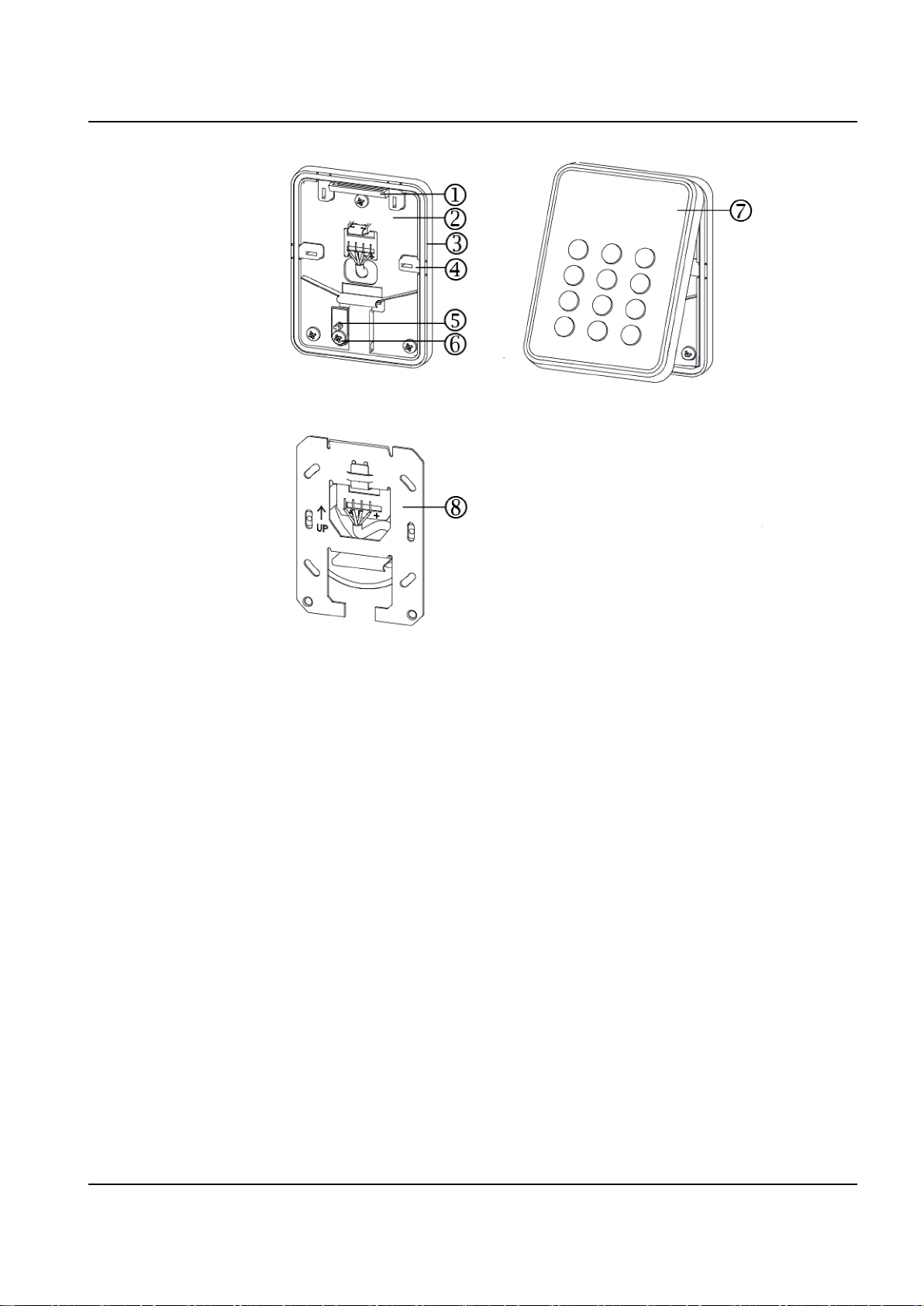
4 Reader components
1. Hinge
2. Base
3.
Cord gasket
4.
Knock outs x 4
5 Tamper base
6. Screw for removal from wall
tamper protection
7 Front
8.
Back box plate
Siemens Switzerland Ltd
7
2017-07-14
Page 8

4 Reader components
1. Screws for back box plate
2. Connector
3. Opening tool – please note that this is a symbolic depiction of the opening tool
8
Siemens Switzerland Ltd
2017-07-14
Page 9

5 Mounting and connecting
The reader enables two different mounting alternatives: surface mounted and back box
mounted. Those come in two different varieties, depending on how the wires are fed or
which kind of back box is used. The reader is delivered with components to support
the two mounting alternatives. Please note that the alternatives only require some of
the different components. Before mounting the reader, identify the parts which are
needed for the appropriate alternative.
Please refer to respective page for:
l "Surface mounted reader" on the next page– the reader is mounted on the base,
which first is fastened on a wall.
l "Surface mounted reader with cables fed from outside" on page11 – the reader is
mounted on the base and the cables are connected via one of the knock outs.
l "Back box mounted reader " on page13 – the reader is partly mounted inside a
back box in a wall. The two extra screws prevent the reader from rotating.
For connecting the cables to the reader, please refer to: "Connecting the cables"
on page 14.
5 Mounting and connecting
Siemens Switzerland Ltd
9
2017-07-14
Page 10
5 Mounting and connecting
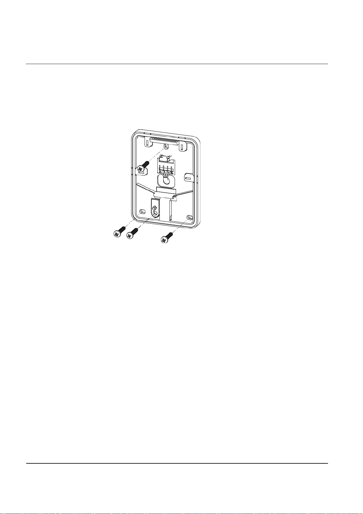
5.1 Surface mounted reader
Use drills and screws appropriate for the surface which the reader is to be mounted
upon. The surface should be flat to ensure a close fit. To attach the base to the wall:
1.
Make a small hole in the base gasket. The cables will be pushed through this hole.
2.
Attach the base to the wall with three screws: one in the middle at the top of the
base, and two in the corners at the bottom of the base.
3.
In case that the removal from wall tamper protection is required, fix the screw into
the hole under the tamper base. Ensure to not use excessive force since this can
damage the tamper base.
4.
Continue to follow the instructions "Connecting the cables" on page14.
10
Siemens Switzerland Ltd
2017-07-14
Page 11
5 Mounting and connecting
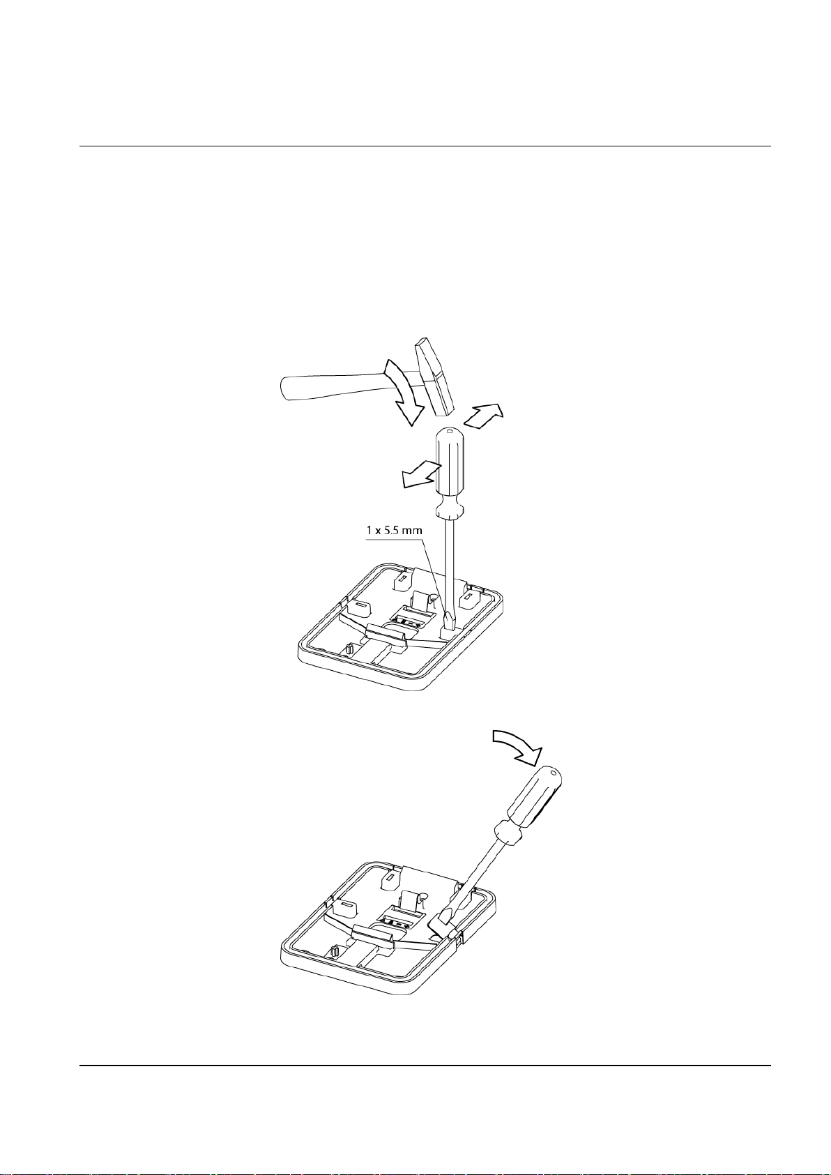
5.2 Surface mounted reader with cables fed from outside
Should the cables be fed from outside:
1.
Remove the cord gasket from the base.
2.
Identify which of the knock outs the cables should be fed through.
3.
Insert the flat head screw driver in the pocket of the knock out.
4.
Hammer the screw driver handle. This will create enough pressure to crack the
exact area of the base which will release the knock out.
5.
Tilt the knock out with the screwdriver.
Siemens Switzerland Ltd
6.
Pull the knock out away from the base.
11
2017-07-14
Page 12
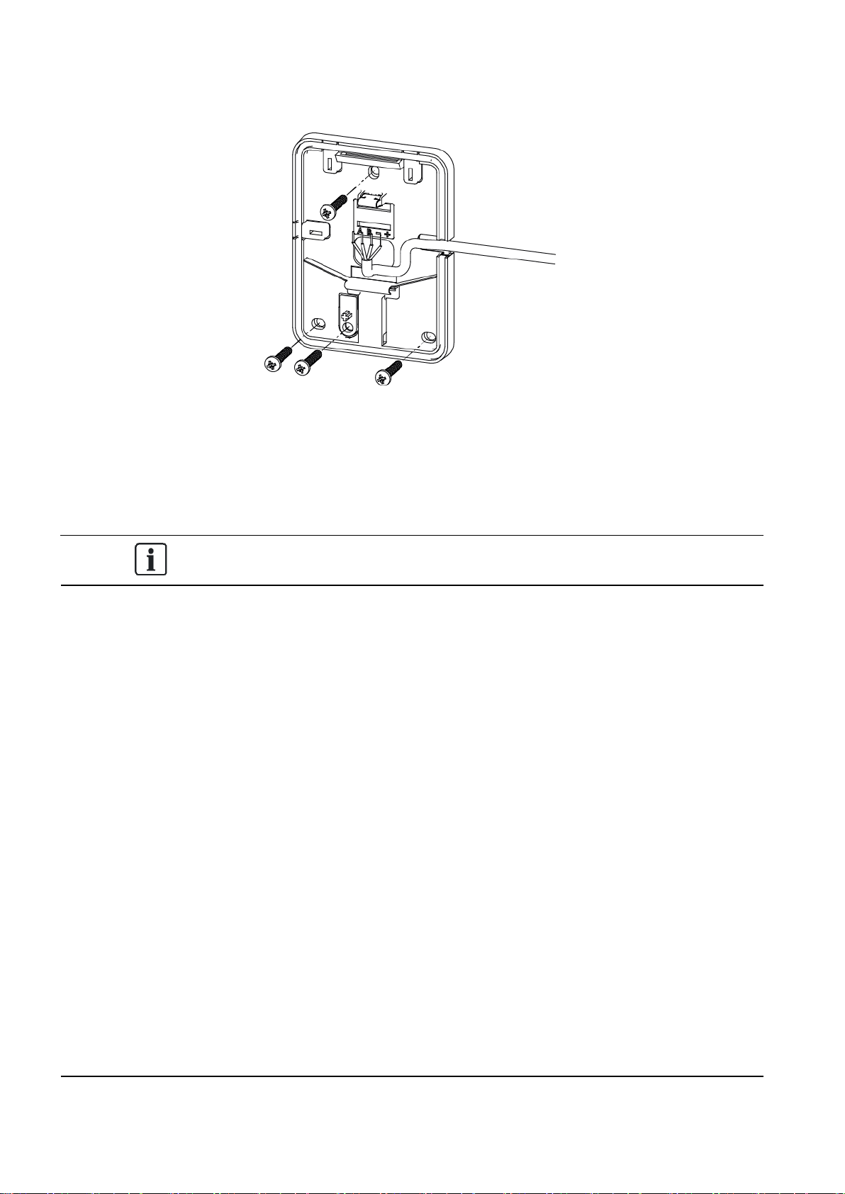
5 Mounting and connecting
7.
Attach the base to the wall with three screws: one in the middle at the top of the
base and two in corners at the bottom of the base.
8.
In case that the removal from wall tamper protection is required, fix the screw into
the hole under the tamper base. Ensure to not use excessive force since this can
damage the tamper base.
9.
Feed the cables through the opening and reinsert the cord gasket. Proceed to the
instructions for "Connecting the cables" on page15.
It is recommended to seal the gap which the knock out creates. Please note that a
reader with a removed knock out is not IP 55.
12
Siemens Switzerland Ltd
2017-07-14
Page 13
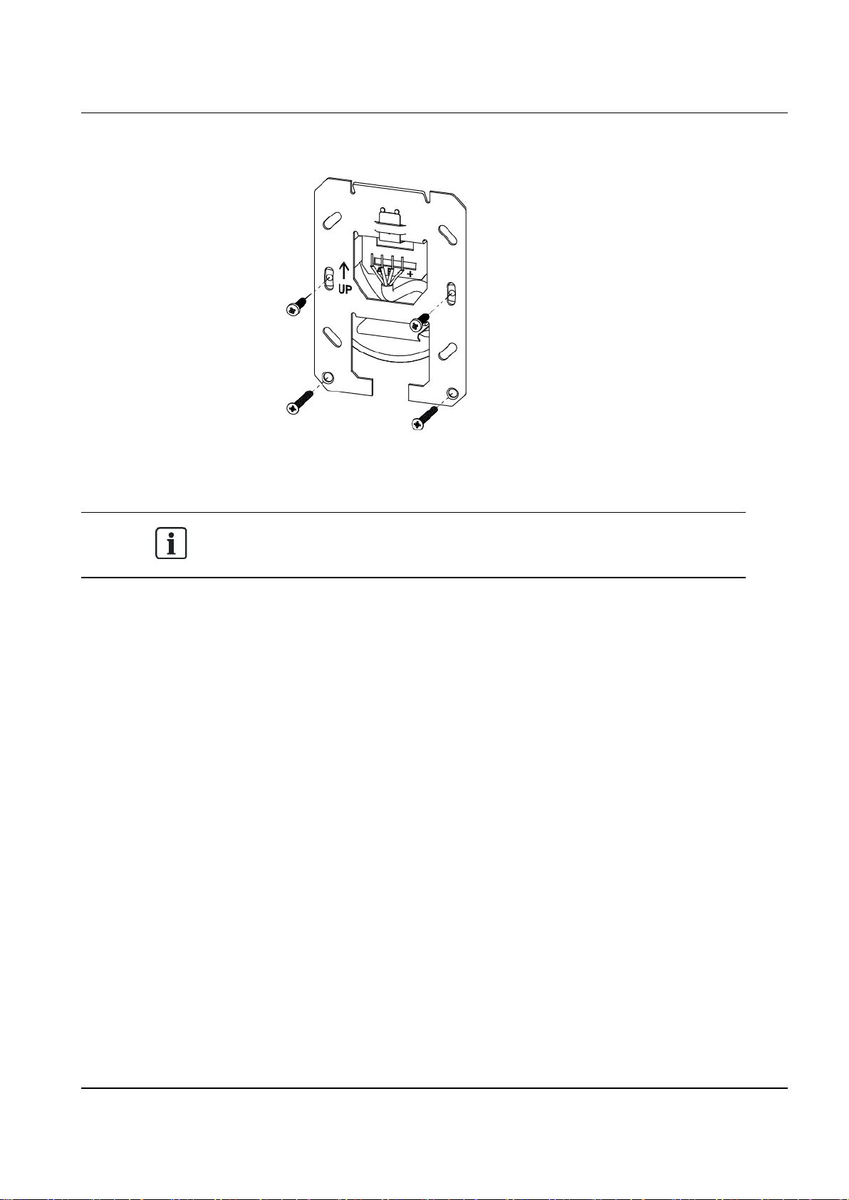
5.3 Back box mounted reader
The reader is mounted on a back box which is attached with two extra screws.
1.
Mount the back box plate on to the back box.
2.
Attach the extra screws at the lower part of the back box plate in order to prevent
rotation.
5 Mounting and connecting
Use only the screws included in the packet for the lower part of the base since
those ensure that the reader front will fit perfectly to be securely fitted over the
back box.
3.
Continue to follow the instructions for "Connecting the cables" on page15
Siemens Switzerland Ltd
13
2017-07-14
Page 14
5 Mounting and connecting
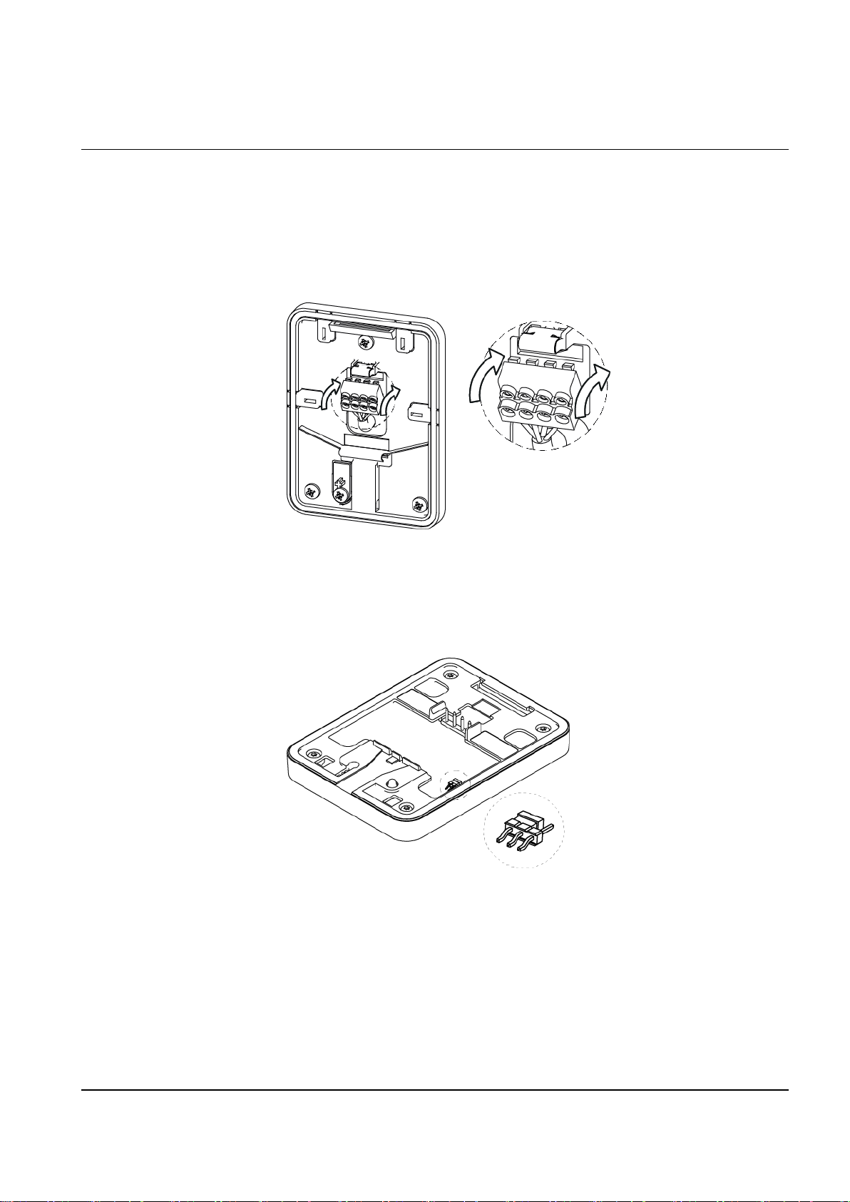
5.4 Connecting the cables
Use a pair twisted screened cable (2 pairs + screen), such as Belden 9502. The cables
are connected on the respective indicators. Should an extension cable be used, the
cables are already attached to the connector.
1.
Attach the cables according to the respective indicators on the connector and the
base: A B - +
2.
Snap the connector in place.
3.
Push the cables back.
4.
On the backside of the front there is an EOL jumper used for RS485 bus termination (see illustration). By default the reader has the termination ON and acts
as the
last
reader on the bus. But if it is an
intermediate
reader on the bus, the
jumper must be removed (or placed in OFF position).
5.
Place the front of the reader with an angle to the hinges at the top of the base.
14
Siemens Switzerland Ltd
2017-07-14
Page 15

5 Mounting and connecting
6.
Fold the front down until the snap lock confirms a secure attachment.
Siemens Switzerland Ltd
15
2017-07-14
Page 16

5 Mounting and connecting
5.5 Disassembling the reader
Should the reader need to be taken apart:
1.
Carefully insert the opening tool in the slot between the base and the front.
2.
Push gently and lift the front of the base.
To remove the connector:
1.
Insert the opening tool as indicated on the picture.
2.
Push down gently and tilt the connector away from the base.
16
Siemens Switzerland Ltd
2017-07-14
Page 17

6 Default settings
Time-out for configuration card 3 seconds
Time-out for displaymessages 7 seconds
Activation time-out 30 seconds
Hold-off time for cardread 100 milliseconds
Reception for card Inactive
Character set Windows 1252
Min background illumination 12
Max background illumination 255
Bus address 0 (Up to eight are supported)
Off-line indication Yes
Backlight Alwaysactive (Never and Timed activation are possible)
6 Default settings
Buzzer volume for keypress 2
Buzzer volume for card read 2
System sound 10
Light frame follows LED indicators Red, yellow, green
Reading MIFARE Classic UID
Reading MIFARE Plus SL1 – SL3 UID
Reading MIFARE DESFireEV1 UID
The card readers are delivered in this default mode. This mode can be altered with the
Configuration Card Creation Tool (3CT), which enables for required settings to be used
for the card readers. For further information, please contact the supplier of this reader.
The readers use FreeRTOS. For further information, please visit www.freertos.org.
Siemens Switzerland Ltd
17
2017-07-14
Page 18

7 Connecting card reader to SiPass integrated
7 Connecting card reader to SiPass integrated
The connection between a card reader and a Reader Interface Module (RIM) is as
follows:
RIM (DRI/ERI) ARxx-MF
12 V
0V
Tx/+
Rx/-
7.1 Setting the card reader address
+
-
A
B
The card readers are delivered in the default mode which is stated in "Default settings"
on page18. The bus address for card readers with default settings is 0. Ensure to
power up the card readers one at the time – this in order to establish the bus addresses
in correct order. When connecting a card reader to a RIM (DRI/ERI), the card reader
and bus address is automatically configured as follows:
1. The first powered up card reader gets bus address 1.
2. The secondly powered up card reader gets bus address 2 and so forth.
When the card reader is first powered, the yellow LED flashes. The flashing lights stop
when it is correctly configured to SiPass integrated. This can be tested by holding a
card in close proximity. A correctly configured card reader acknowledges the card
according to the SiPass integrated settings.
Please note that a new card reader will always get the next free bus address. Should a
card reader with bus address 5 be removed and a new card reader be installed, the
new card reader will get address 5.
18
Siemens Switzerland Ltd
2017-07-14
Page 19

7 Connecting card reader to SiPass integrated
Siemens Switzerland Ltd
19
2017-07-14
Page 20

8 Disposal
8 Disposal
All electrical and electronic products should be disposed of separately from the municipal waste
stream via designated collection facilities appointed by the government or the local authorities.
This crossed-out wheeled bin symbol on the product means the product is covered by the
European Directive 2002/96/EC.
The correct disposal and separate collection of your old appliance will help prevent potential
negative consequences for the environment and human health. It is a precondition for reuse and
recycling of used electrical and electronic equipment. For more detailed information about
disposal of your old appliance, please contact your city office, waste disposal service or the
shop where you purchased the product.
20
Siemens Switzerland Ltd
2017-07-14
Page 21

Scale 1:1
Units: mm
85
5
5
114
86
42.2
184
12
12.5
16
14 42.5
60
95
Page 22

Issued by
Siemens Switzerland Ltd
Gubelstrass e 22
6300 Zug
Switzerland
www. siemens.com/security-solutions
Document Nr A-100010-9
Edition Date
2017-07-14
© 2017 Copyright by Siemens Switzerland Ltd
Data and design subject to change without notice.
Supply subject to availability.
Page 23

VR40S-MF VR10S-MF
VR10S-MF VR40S-MF
Installation and Mounting
Version 9.0
Vanderbilt International (IRL) Ltd.
Page 24

Data anddesign subject to change without notice. / Supply subject to availability.
© 2017 Copyright by Vanderbilt International(IRL) Ltd.
We reserve all rights in this document and in thesubject thereof. By acceptance of the document the recipient acknowledges these rights and
undertakes not to publish the document nor the subject thereof in full or in par t, nor to make them availableto any third partywithout our prior
express written authorization, nor to use it for any purpose other than for which it was delivered to him.
Document nr: A-100224-9
Page 25

Content
Content 3
1 Introduction 4
2 Technical data 5
3 Safety regulations 6
3.1 Standards and guidelines 6
3.2 FCC statements 6
4 Reader components 7
5 Mounting and connecting 9
5.1 Surface mounted reader 10
5.2 Surface mounted reader with cables fed from outside 11
5.3 Back box mounted reader 13
5.4 Back box mounted reader with adapter plate 14
5.5 Connecting the cables 15
5.6 Disassembling the reader 17
6 Default settings 18
7 Connecting card reader to SiPass integrated 19
7.1 Setting the card reader address 19
8 Disposal 21
Page 26

1 Introduction
1 Introduction
The VR10S-MF and VR40S-MF are executively designed card readers for modern
security. The encryption*) is conducted via a protocol which ensures a high level of
security, providing that the card reader and system are set to the secure mode.
When the secure mode is activated, the communication from neither the reader nor
the system they are connected to can be extracted. They are made of hardwearing
materials and will endure most weather conditions. The readers are easy to mount
and connect, and can be mounted on a flat surface or partly inside a back box. They
can be cleaned with most kind of domestic detergents. Both readers have a
multicolour light frame. The VR40S-MF has a keypad and a high contrast display.
*) Only valid for SiPass integrated MP2.65 – or later
4
Vanderbilt International (IRL) Ltd.
2017-07-14
Page 27

2 Technical data
2 Technical data
VR10S-MF Mifare card reader
standard
VR40S-MF Mifare card reader
standard with keypad and display
Protocol OSDP OSDP
Interface to controller RS485 RS485
Operating voltage 8.5 – 30.0 VDC 8.5 – 30.0 VDC
Power consumption DC 12V 43mA Peak 168mA
DC 24V 26mA Peak 100mA
DC 12V 60mA Peak 220mA
DC 24V 40mA Peak 125mA
Tamper protection Yes Yes
Card technology Mifare Mifare
Card compatibility Mifare Classic
Mifare Plus
Mifare DESfire EV1
Mifare Classic
Mifare Plus
Mifare DESfire EV1
Reading distance Up to 6 cm Up to 6 cm
Indicators 3 x LED (red/yellow/green)
1 x Buzzer
Multicolor light frame
3 x LED (red/yellow/green)
1 x Buzzer
Multicolor light frame
Keypad No Yes
Display No Yes, graphic monochrome OLED
Operating temperature - 40°C to + 55°C* - 40°C to + 55°C*
IP rating IP55** IP55**
IK class 08 08
Housing Zinc casted metal bezel with
polycarbonate plastic front
Zinc casted metal bezel with
polycarbonate plastic front
Color Black, matt chrome Black, matt chrome
Dimensions (W x H x D) Surface mounted: 85 x 114 x 22
Back box mounted: 85 x 114 x 14
Approvals
CE according to Radio
Equipment Directives, FCC
Certified
Surface mounted: 85 x 114 x 22
Back box mounted: 85 x 114 x 14
CE according to Radio
Equipment Directives, FCC
Certified
* Only applicable for surface mounted readers. Back box mounted readers are specified from -10°C to +55°C.
** Only applicable for surface mounted readers. Back box mounted readers are specified to IP3X.
V
anderbilt International (IRL) Ltd.
5
2017-07-14
Page 28

3 Safety regulations
3 Safety regulations
General
l Follow all warnings and instructions marked on the device.
l Keep this document for reference purposes.
l Please take into account any additional country-specific, local laws, safety
standards or regulations concerning installation, operation and disposal of the
product.
Liability claim
l Do not make any changes or modifications to the device.
l Use only spare parts and accessories that have been approved by the
manufacturer.
3.1 Standards and guidelines
European directives
Vanderbilt hereby declares that this product is in compliance with the
essential requirements and other relevant provisions of Radio Equipment
Directive 2014/53/EU.
The EC Declaration of Conformity is available from your Vanderbilt sales office or:
Vanderbilt International (IRL) Ltd.
Clonshaugh Business and Technology Park
Clonshaugh
Dublin 17
Ireland
.
3.2 FCC statements
Model No.
FCC ID
This device complies with part 15 of the FCC rules. Operation is subject to the
following two conditions: (1) this device may not cause harmful interference,
and (2) this device must accept any interference received, including
interference that may cause undesired operation.
VR10S-MF VR40S-MF
2AHDLNGCR 2AHDLNGCR
6
Vanderbilt International (IRL) Ltd.
Warning: Changes or modifications not expressly approved by the party
responsible for compliance could void the User`s authority to operate the
equipment.
2017-07-14
Page 29

4 Reader components
4 Reader components
1. Hinge
2. Base
Cord gasket
3.
Knock outs x 4
4.
5 Tamper base
Screw for removal from wall tamper protection
6.
7 Front
Back box plate
8.
Vanderbilt International (IRL) Ltd.
7
2017-07-14
Page 30

4 Reader components
1. Screws for back box plate
2. Connector
3. Opening tool – please note that this is a symbolic depiction of the opening tool
8
Vanderbilt International (IRL) Ltd.
2017-07-14
Page 31

5 Mounting and connecting
The reader enables two different mounting alternatives: surface mounted and back box
mounted. Those come in two different varieties, depending on how the wires are fed or
which kind of back box is used. The reader is delivered with components to support
the two mounting alternatives. Please note that the alternatives only require some of
the different components. Before mounting the reader, identify the parts which are
needed for the appropriate alternative.
Please refer to respective page for:
l "Surface mounted reader" on the next page– the reader is mounted on the base,
which first is fastened on a wall.
l "Surface mounted reader with cables fed from outside" on page11 – the reader is
mounted on the base and the cables are connected via one of the knock outs.
l "Back box mounted reader " on page13 – the reader is partly mounted inside a
back box in a wall. The two extra screws prevent the reader from rotating.
For connecting the cables to the reader, please refer to:
"Connecting the cables" on page14.
5 Mounting and connecting
Vanderbilt International (IRL) Ltd.
9
2017-07-14
Page 32

5 Mounting and connecting
5.1 Surface mounted reader
Use drills and screws appropriate for the surface which the reader is to be mounted
upon. The surface should be flat to ensure a close fit. To attach the base to the wall:
1.
Make a small hole in the base gasket. The cables will be pushed through this hole.
2.
Attach the base to the wall with three screws: one in the middle at the top of the
base, and two in the corners at the bottom of the base.
3.
In case that the removal from wall tamper protection is required, fix the screw into
the hole under the tamper base. Ensure to not use excessive force since this can
damage the tamper base.
4.
Continue to follow the instructions "Connecting the cables" on page15.
10
Vanderbilt International (IRL) Ltd.
2017-07-14
Page 33

5 Mounting and connecting
5.2 Surface mounted reader with cables fed from outside
Should the cables be fed from outside:
1.
Remove the cord gasket from the base.
2.
Identify which of the knock outs the cables should be fed through.
3.
Insert the flat head screw driver in the pocket of the knock out.
4.
Hammer the screw driver handle. This will create enough pressure to crack the
exact area of the base which will release the knock out.
5.
Tilt the knock out with the screwdriver.
Vanderbilt International (IRL) Ltd.
6.
Pull the knock out away from the base.
11
2017-07-14
Page 34

5 Mounting and connecting
7.
Attach the base to the wall with three screws: one in the middle at the top of the
base and two in corners at the bottom of the base.
8.
In case that the removal from wall tamper protection is required, fix the screw into
the hole under the tamper base. Ensure to not use excessive force since this can
damage the tamper base.
9.
Feed the cables through the opening and reinsert the cord gasket. Proceed to the
instructions for "Connecting the cables" on page15.
It is recommended to seal the gap which the knock out creates. Please note that a
reader with a removed knock out is not IP 55.
12
Vanderbilt International (IRL) Ltd.
2017-07-14
Page 35

5.3 Back box mounted reader
The reader is mounted on a back box which is attached with two extra screws.
1.
Mount the back box plate on to the back box.
2.
Attach the extra screws at the lower part of the back box plate in order to prevent
rotation.
5 Mounting and connecting
Use only the screws included in the packet for the lower part of the base since
those ensure that the reader front will fit perfectly to be securely fitted over the
back box.
3.
Continue to follow the instructions for "Connecting the cables" on page14
Vanderbilt International (IRL) Ltd.
13
2017-07-14
Page 36

5 Mounting and connecting
5.4 Connecting the cables
Use a pair twisted screened cable (2 pairs + screen), such as Belden 9502. The cables
are connected on the respective indicators. Should an extension cable be used, the
cables are already attached to the connector.
1.
Attach the cables according to the respective indicators on the connector and the
base: A B - +
2.
Snap the connector in place.
3.
Push the cables back.
4.
On the backside of the front there is an EOL jumper used for RS485 bus termination (see illustration). By default the reader has the termination ON and acts
as the
last
reader on the bus. But if it is an
intermediate
reader on the bus, the
jumper must be removed (or placed in OFF position).
5.
Place the front of the reader with an angle to the hinges at the top of the base.
14
Vanderbilt International (IRL) Ltd.
2017-07-14
Page 37

5 Mounting and connecting
6.
Fold the front down until the snap lock confirms a secure attachment.
Vanderbilt International (IRL) Ltd.
15
2017-07-14
Page 38

5 Mounting and connecting
5.5 Disassembling the reader
Should the reader need to be taken apart:
1.
Carefully insert the opening tool in the slot between the base and the front.
2.
Push gently and lift the front of the base.
To remove the connector:
1.
Insert the opening tool as indicated on the picture.
2.
Push down gently and tilt the connector away from the base.
16
Vanderbilt International (IRL) Ltd.
2017-07-14
Page 39

6 Default settings
Time-out for configuration card 3 seconds
Time-out for displaymessages 7 seconds
Activation time-out 30 seconds
Hold-off time for cardread 100 milliseconds
Reception for card Inactive
Character set Windows 1252
Min background illumination 12
Max background illumination 255
Bus address 0 (Up to eight aresupported)
Off-line indication Yes
Backlight Alwaysactive (Never and T imed activation are possible)
6 Default settings
Buzzer volume for key press 2
Buzzer volume for card read 2
System sound 10
Light frame follows LED indicators Red, yellow, green
Reading MIFARE Classic UID
Reading MIFARE PlusSL1 – SL3 UID
Reading MIFARE DESFire EV1 UID
The card readers are delivered in this default mode. This mode can be altered with the
Configuration Card Creation Tool (3CT), which enables for required settings to be used
for the card readers. For further information, please contact the supplier of this reader.
The readers use FreeRTOS. For further information, please visit www.freertos.org.
Vanderbilt International (IRL) Ltd.
17
2017-07-14
Page 40

7 Connecting card reader to SiPass integrated
7 Connecting card reader to SiPass integrated
The connection between a card reader and a Reader Interface Module (RIM) is as
follows:
RIM (DRI/ERI) VRxx-MF
12 V
0V
Tx/+
Rx/-
7.1 Setting the card reader address
+
-
A
B
The card readers are delivered in the default mode which is stated in "Default settings"
on page18. The bus address for card readers with default settings is 0. Ensure to
power up the card readers one at the time – this in order to establish the bus addresses
in correct order. When connecting a card reader to a RIM (DRI/ERI), the card reader
and bus address is automatically configured as follows:
1. The first powered up card reader gets bus address 1.
2. The secondly powered up card reader gets bus address 2 and so forth.
When the card reader is first powered, the yellow LED flashes. The flashing lights stop
when it is correctly configured to SiPass integrated. This can be tested by holding a
card in close proximity. A correctly configured card reader acknowledges the card
according to the SiPass integrated settings.
Please note that a new card reader will always get the next free bus address. Should a
card reader with bus address 5 be removed and a new card reader be installed, the
new card reader will get address 5.
18
Vanderbilt International (IRL) Ltd.
2017-07-14
Page 41

7 Connecting card reader to SiPass integrated
Vanderbilt International (IRL) Ltd.
19
2017-07-14
Page 42

8 Disposal
8 Disposal
All electrical and electronic products should be disposed of separately from the municipal waste
stream via designated collection facilities appointed by the government or the local authorities.
This crossed-out wheeled bin symbol on the product means the product is covered by the
European Directive 2002/96/EC.
The correct disposal and separate collection of your old appliance will help prevent potential
negative consequences for the environment and human health. It is a precondition for reuse and
recycling of used electrical and electronic equipment. For more detailed information about
disposal of your old appliance, please contact your city office, waste disposal service or the
shop where you purchased the product.
20
Vanderbilt International (IRL) Ltd.
2017-07-14
Page 43

Scale 1:1
Units: mm
85
5
5
114
86
42.2
184
12
12.5
16
14 42.5
60
95
Page 44

Issued by
Vanderbilt International (IRL) Ltd.
Clonshaugh Business and Technology Park
Clonshaugh
Dublin 17
Ireland
www. vanderbiltindustries.com
Document Nr A-100224-9
Edition Date
2017-07-14
© 2017 Copyright by Vanderbilt International (IRL) Ltd.
Data and design subject to change without notice.
Supply subject toavailability.
 Loading...