

Page 1

Mullion Reader
User Manual
Document ID: A-100410-b
Edition date: 15.04.2019
Page 2

Data and design subject to change without notice. / Supply subject to availability.
© 2019 Copyright by Vanderbilt
We r eserve allrights in this document and in the subjectthereof. By acceptance of the document the recipient acknowledges these rights and
undertakes not to publish the document nor the subject thereof in fullor in par t, nor to make them availableto any third party without our prior
express written authorization, nor to use it for any purpose other than for which it was delivered to him.
MIFARE and MIFARE Classicare trademarks of NXP B.V.
MIFARE DESFire are r egistered trademarks of NXP B.V. and are used under license.
Hereby, Vanderbilt International (IRL) Ltd declares that this equipment type is in compliance with the following EU Directives for CE marking:
• Directive 2014/30/EU (ElectromagneticCompatibilityDirective)
• Directive 2014/53/EU (Radio Equipment Directive)
• Directive 2011/65/EU (Restriction of the use of certain hazardous substances Directive)
The full text of the EU declaration of conformity is availableat: http://van.fyi?Link=DoC
DA
DE
EN
ES
FR
SV
&
http://van.fyi?Link=Mullion_Reader
Page 3

Table of Contents
1 Introduction 5
2 Technical data 6
2.1 FCC statements 7
3 Safety regulations 8
4 Reader components and package contents 9
4.1 Reader components 9
4.2 Package contents 9
5 Mounting and connecting 10
5.1 Mounting a reader 10
5.2 Mounting a reader with cables fed from the side 11
5.3 Connecting the cables 13
5.3.1 Connecting the reader in OSDP mode 13
5.3.2 Connecting the reader in Wiegand mode 14
5.4 Setting the Jumpers 16
5.5 Setting the Jumpers for OSDP 16
5.6 Setting the Jumpers for Wiegand 17
5.7 Reverse mode Wiegand 19
5.8 Programming a reader for reverse mode transmission 20
5.8.1 Reverting to standard mode Wiegand 20
5.9 Programming a Reverse mode transmission reader for 26 Bit Wiegand 20
5.9.1 Re-programming a reverse mode transmission reader away from 26 Bit Wiegand 21
5.10 Default Configuration Card 21
5.10.1 37 Bit Wiegand. 21
6 Closing the reader 22
7 Disassembling the reader 23
7.1 To disassemble the reader: 23
7.2 To remove the terminal block: 24
8 Default settings 25
8.1 3CT Tool 25
8.2 Setting burst mode using the keypad 26
9 Connecting the reader to SiPass integrated 27
9.1 Connecting the reader to SiPass integrated in OSDP mode 27
9.2 Setting OSDP address for the reader 28
9.3 Connecting the reader to SiPass integrated in Wiegand mode 28
10 Connecting the reader to ACT 29
10.1 Connecting the reader to ACT in OSDP mode 29
10.2 Setting the OSDP address for the reader 30
Page 4

10.3 Connecting the reader to ACT in Wiegand mode 32
11 Connecting the reader to SPC 33
Page 5

1 Introduction
The VR20M-MFand VR50M-MF are mullion-mount card readers with modern anti-hacking security over
OSDP and support for the traditional Wiegand protocol. When installed as part of a secure system over
OSDP, the communication from the reader or the controller they are connected to cannot be compromised.
The readers are made of hard wearing materials and will endure most weather conditions. The readers are
easy to mount and can be mounted on a flat surface. The readers can be cleaned with most kinds of
domestic detergents. All readers have a multicolour light frame. The VR50M-MF has a keypad for PIN
code.
© Vanderbilt 2019 5
A-100410-b
15.04.2019
Page 6

2 Technical data
Protocol OSDP or Wiegand OSDP or Wiegand
Interface to controller RS485 or Wiegand RS485 or Wiegand
Operating voltage 8.5 – 30.0VDC 8.5 – 30.0VDC
VR20M-MF VR50M-MF
Power consumption
Tamper protection Yes Yes
Card technology
Card compatibility
Reading distance
Indicators
Keypad No Yes
Operating temperature - 40°C to + 70°C - 40°C to + 70°C
DC 12V 50mA Peak 150mA
DC 24V 35mA Peak 100mA
MIFARE
MIFARE Classic
MIFARE Plus
MIFARE DESFire EV1/ EV2
MIFARE Classic-up to 6 cm
MIFARE Plus-up to 6 cm
MIFARE DESfire EV1/ EV2-the
card must be held to the reader
3 x LED (red/yellow/green)
1 x Buzzer
Multicolour light frame
TM
DC 12V 50mA Peak 150mA
DC 24V 35mA Peak 100mA
MIFARE
MIFARE Classic
MIFARE Plus
MIFARE DESFire EV1/ EV2
MIFARE Classic-up to 6 cm
MIFARE Plus-up to 6 cm
MIFARE DESfire EV1/ EV2-the
card must be held to the reader
3 x LED (red/yellow/green)
1 x Buzzer
Multicolour light frame
IP rating IP55 IP55
IK class 08 08
Housing
Color Black, matt chrome Black, matt chrome
Dimensions (WxHxD) mm Surface mounted: 48 x 129 x 22 Surface mounted: 48 x 129 x 24
© Vanderbilt 2019 6
Zinc cast metal bezel with
polycarbonate plastic front
Zinc cast metal bezel with
polycarbonate plastic front
A-100410-b
15.04.2019
Page 7

Mullion Reader – User Manual Technical data
Cable length guide
OSDP Max. 8 readers Max. 1 km Belden cable
Wiegand Max. 4 readers Max. 30m copper cable (0.5 mm)
2.1 FCC statements
Model No. VR20M-MF VR50M-MF
FCC ID 2AHDLMULL 2AHDLMULL
This device complies with part 15 of the FCC rules. Operation is subject to the following two conditions: (1)
this device may not cause harmful interference, and (2) this device must accept any interference received,
including interference that may cause undesired operation.
Warning: Changes or modifications not expressly approved by the party responsible for compliance could
void the User`s authority to operate the equipment.
© Vanderbilt 2019 7
A-100410-b
15.04.2019
Page 8

3 Safety regulations
General
l Follow all warnings and instructions marked on the device.
l Keep this document for reference purposes.
l Please consider any additional country-specific, local laws, safety standards, or regulations
concerning installation, operation, and disposal of the product.
Liability claim
l Do not make any changes or modifications to the device.
l Use only spare parts and accessories that have been approved by the manufacturer.
© Vanderbilt 2019 8
A-100410-b
15.04.2019
Page 9
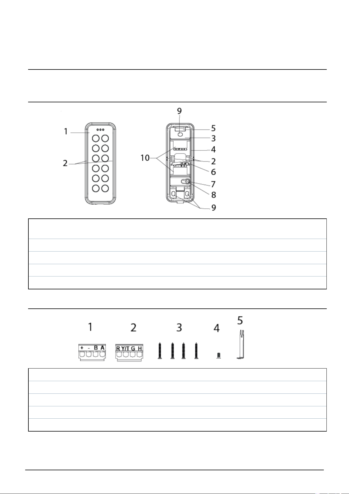
4 Reader components and package contents
The following diagrams identify the reader components and the items that come packaged with the reader.
4.1 Reader components
1 Front 6
2 Knockouts x 2 7 Tamper base
3 Base 8 Screw for tamper protection
4 Gasket 9 Mounting holes
5 Hook 10 Upper and lower terminal block locations
Location where cables can come through the
back
4.2 Package contents
1 + - B A terminal block for OSDP and Wiegand (lower terminal block)
2 R Y/T G H terminal block for Wiegand (upper terminal block)
3 Mounting/Tamper screws
4 Cover screw
5 Opening tool
© Vanderbilt 2019 9
A-100410-b
15.04.2019
Page 10
5 Mounting and connecting
The mullion readers are surface-mounted readers. The readers can be mounted with cables led through the
back of the unit or led in from either side through knockout gaps.
For wiring details please refer to:
l Connecting the cables on page13.
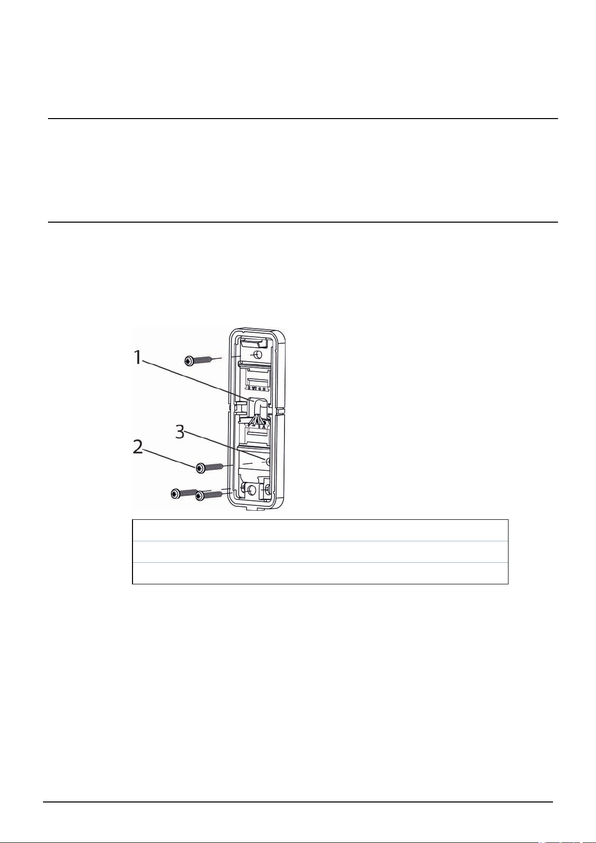
5.1 Mounting a reader
To ensure a close fit, mount the reader on a flat surface.
To attach the base to a surface:
1. Make a small hole in the back of the base gasket (item1 in the diagram below). Use this hole to feed
the cable through the gasket and into the reader base.
2. Attach the base to the wall with three screws: one in the middle at the top of the base, and one in
each of the corners at the bottom of the base.
1 Cable entry through base gasket
2 Tamper screw
3 Tamper base
3. If tamper protection is required, fix the screw (item 3) into the tamper base (item 2).
Do not over tighten the screw as this can damage the tamper base.
4. Continue to follow the instructions detailed in Connecting the cables on page13.
© Vanderbilt 2019 10
A-100410-b
15.04.2019
Page 11
Mullion Reader – User Manual Mounting and connecting
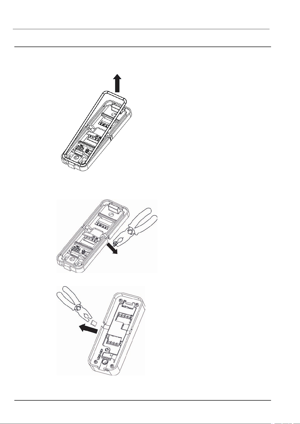
5.2 Mounting a reader with cables fed from the side
If the cables are fed from the side:
1. Remove the gasket from the base.
2. Identify which of the knockouts the cables should be fed through.
3. Use a pliers to pull the knockout away from the base.
4. Remove the corresponding knockout on the cover.
© Vanderbilt 2019 11
A-100410-b
15.04.2019
Page 12

Mullion Reader – User Manual Mounting and connecting
5. Attach the base to the wall with three screws: one in the middle at the top of the base and one in
each of the corners at the bottom of the base.
1 Tamper base
2 Tamper screw
6. If tamper protection is required, fix the screw into the hole on the tamper base. Do not over
tighten the screw as this can damage the tamper base.
7. Feed the cables through the opening and reinsert the gasket. Follow the instructions for
Connecting the cables on the next page.
Vanderbilt recommend sealing the gap that the knockout creates with a silicon
sealant. Do this after you have closed the reader. Please note that a reader with a
removed knockout does not meet the standard for IP 55.
© Vanderbilt 2019 12
A-100410-b
15.04.2019
Page 13

Mullion Reader – User Manual Mounting and connecting
5.3 Connecting the cables
5.3.1 Connecting the reader in OSDP mode
Use the terminal block marked +-BA (see number 2 in Package contents on page9 and a pair of twisted
screened cable to connect the cables in OSDP mode.
1. Attach the cables according to the respective indicators on the second, +-BA terminal block (lower
terminal block) and the base:
Reader Controller
+ +12V
- 0V
B B
A A
2. Insert the ridge on the end of the terminal block marked +-BA into the slot marked +,-,B,A.
3. Gently push the terminal block towards the base until it clicks.
4. Push the cables back.
Please note that you must set the Jumpers to configure your application.
For more information on setting the Jumpers in OSDP mode see Setting the
Jumpers for OSDP on page16.
For more information on setting the Jumpers in Wiegand mode see Setting the
Jumpers for Wiegand on page17.
On the reverse of the front plate, Jumper 3 is used to determine EOL (see the diagram in Connecting
the cables above). By default EOL is ON and the reader acts as the last reader on the bus. However,
if the reader is an intermediate reader on the bus, Jumper 3 must be removed.
© Vanderbilt 2019 13
A-100410-b
15.04.2019
Page 14

Mullion Reader – User Manual Mounting and connecting
5.3.2 Connecting the reader in Wiegand mode
Use the terminal blocks marked +-BA and RY/TGH and a pair of twisted screened cables (4 pairs +
screen), such as Belden 9502 to connect the reader in Wiegand mode.
1. Attach the cables according to the respective indicators on the communication and power
terminal block (+-BA terminal block (lower terminal block)):
Reader Controller
+ +12V
- 0V
B Wiegand D1
A Wiegand D0
2. Attach the cables on the LED, tamper,and horn terminal block (RY/TGH terminal block (upper
terminal block)):
Reader Controller (Generic) Controller (SPC) Controller (ACT)
R Red LED VO1 Red
Y/T* Tamper input Zone Input (tamper)
1
Tamper input
1
G Green LED VA1 Green
H Buzzer output System Output
1
Buzzer output
1
*The Tamper output (default setting) connection may alternatively be configured to provide a
Yellow input to the reader. The Tamper output/ Yellow input options are mutually exclusive.
1
This connection is optional.
When the tamper output option is configured there is no yellow indication input. In this instance,
you can turn on the yellow indication LED by setting both the red and green indication inputs low.
Both the red and green indication LEDs are turned off at this time.
The buzzer is activated by setting the horn input low. The buzzer is deactivated by setting the horn
input high.
© Vanderbilt 2019 14
A-100410-b
15.04.2019
Page 15

Mullion Reader – User Manual Mounting and connecting
3. Insert the ridge on the end of the upper or lower terminal block into the corresponding slot.
4. Gently push the terminal block towards the base until it clicks.
5. Remove the Jumper 3 (see the diagram in Connecting the cables on page13). Jumper 3 is used to
determine EOL. By default the reader has EOL ON. EOL is always off in Wiegand mode.
Please note that you must set the Jumpers to configure your application. For more information on
setting the Jumpers in Wiegand mode see Setting the Jumpers for Wiegand on page17.
© Vanderbilt 2019 15
A-100410-b
15.04.2019
Page 16

Mullion Reader – User Manual Mounting and connecting
5.4 Setting the Jumpers
There are three jumpers inside the front of the reader. Use the jumpers to set the reader to OSDP or
Wiegand mode, to set OSDP Addressing or Wiegand format, and to set the End Of Line (EOL) status
for the reader.
1 Set reader to OSDP or Wiegand mode
2 Set OSDP addressing or Wiegand formats
3 Set End Of Line (EOL) status for the reader
* This indicates the bottom of the reader
5.5 Setting the Jumpers for OSDP
The diagrams below show how to position the Jumpers to get the desired functions from the terminal
blocks. Note that the EOL is ON for a sole reader or for the last reader on the RS485 bus.
Jumper 1
© Vanderbilt 2019 16
A-100410-b
15.04.2019
Page 17

Mullion Reader – User Manual Mounting and connecting
Jumper 1 is ON to select OSDP.
Jumper 2
l Jumper 2 is ON the first two pins for OSDP Address 1.
l Jumper 2 is ON the bottom two pins for OSDP Address 2.
l Jumper 2 is OFF for OSDP Programmable Address.
Jumper 3
l Jumper 3 is ON to enable EOL.
l Jumper 3 is OFF to disable EOL.
5.6 Setting the Jumpers for Wiegand
By default, the VR20 and VR50 Mullion readers are configured to transmit standard mode 32 Bit Wiegand,
37 Bit Wiegand, or 56 Bit Wiegand.
Some installations may require transmission in Reverse Mode for 26 Bit Wiegand, 32 Bit Wiegand or 56 Bit
Wiegand.
If you are adding this reader to an existing Reverse Mode installation, you must follow the procedure to
program the reader to Reverse Mode Wiegand.
For more information, please refer to:
l Reverse mode Wiegand on page19.
© Vanderbilt 2019 17
A-100410-b
15.04.2019
Page 18

Mullion Reader – User Manual Mounting and connecting
If the existing installation uses 26 Bit Wiegand, you must follow the additional procedure to program the
reader to transmit in Reverse Mode 26 Bit Wiegand.
For more information, please refer to:
l Reverse mode Wiegand on the next page.
Only one of the two modes may be configured at a time.
Wiegand - Standard mode transmission
Wiegand Standard transmission
56 Bit Yes
37 Bit Yes
32 Bit Yes
26 Bit No
Wiegand - Reverse mode transmission
Reverse
Wiegand
transmission
56 Bit Yes
mode
Re-program
necessary
Yes
37 Bit No
32 Bit Yes
26 Bit Yes
Yes
Yes
Re-program necessary
Procedure
Programming a reader for reverse
mode transmission on page20
Programming a reader for reverse
mode transmission on page20
Programming a reader for reverse
mode transmission on page20
No
No
No
Mandatory
additional
procedure
No
No
Programming a
Reverse mode
transmission
reader for 26 Bit
Wiegand on
page20
The diagrams below show how to position the Jumpers to get the desired functions from the terminal
blocks. Note that in Wiegand mode EOL is not fitted. Wiegand can be set at 32 bit, 37 bit, or 56 bit.
Jumper 1
Jumper 1 is OFF to select Wiegand.
© Vanderbilt 2019 18
A-100410-b
15.04.2019
Page 19

Mullion Reader – User Manual Mounting and connecting
Jumper 2
l Jumper 2 is ON the first two pins for Wiegand 32 bit.
l Jumper 2 is ON the bottom two pins for Wiegand 56 bit.
l Jumper 2 is OFF for Wiegand 37 bit.
Jumper 3
l Jumper 3 is OFF to disable EOL.
l Jumper 3 is always OFF in Wiegand mode.
5.7 Reverse mode Wiegand
Some installations may require transmission in Reverse Mode for 26 Bit Wiegand, 32 Bit Wiegand or 56 Bit
Wiegand.
To add a reader to an existing Reverse Mode installation, you must follow the procedure to program the
reader to Reverse Mode Wiegand. For more information, see Programming a reader for reverse mode
transmission on the facing page.
If the existing installation uses 26 Bit Wiegand, you must follow an additional procedure to program the
reader to transmit in Reverse Mode 26 Bit Wiegand. For more information, see Programming a Reverse
mode transmission reader for 26 Bit Wiegand on the facing page.
Only one of the two modes may be configured at a time.
© Vanderbilt 2019 19
A-100410-b
15.04.2019
Page 20

Mullion Reader – User Manual Mounting and connecting
5.8 Programming a reader for reverse mode transmission
To provide backwards compatibility to V1.08, V1.09, and V1.12 Mullion readers, you can program the
reader for Reverse mode transmission.
1. Remove the Base of the reader from the Front of the reader.
2. Power down the reader if connected.
3. Connect the Green to the Tamper connection.
4. Place Jumper 2 in the lower position.
5. Remove Jumper 1.
6. Power up the reader.
The reader beeps the affirmation tone and the green indication LED flashes. The reader is now in
VR firmware 1.X Wiegand compatible mode.
7. Power down the reader.
8. Disconnect the Green from the Tamper connection.
9. Place Jumper 2 in the appropriate position for the number of Weigand bits.
For 32 Bit Wiegand, place Jumper 2 in the upper position.
For 56 Bit Wiegand, place Jumper 2 in the lower position.
For 26 Bit Wiegand you must re-progamme the reader into 26 Bit mode.
10. Continue with the installation.
5.8.1 Reverting to standard mode Wiegand
To return the reader to the standard data sequence for Wiegand, follow the steps below:
1. Remove the Base of the reader from the Front of the reader.
2. Power down the reader if connected.
3. Connect the Green to the Tamper connection.
4. Place Jumper 2 in the lower position.
5. Remove Jumper 1.
6. Power up the reader.
The reader beeps the affirmation tone and the green indication LED flashes. The reader is now in
standard mode.
7. Power down the reader.
8. Disconnect the Green input from the Tamper connection.
9. Place Jumper 2 in the appropriate position for the number of Weigand bits.
For 32 Bit Wiegand, place Jumper 2 in the upper position.
For 56 Bit Wiegand, place Jumper 2 in the lower position.
For 37 Bit Wiegand , remove the Jumper.
10. Continue with the installation.
5.9 Programming a Reverse mode transmission reader for 26 Bit Wiegand
The reader may programmed into 26 Bit Wiegand mode as follows;
© Vanderbilt 2019 20
A-100410-b
15.04.2019
Page 21

Mullion Reader – User Manual Mounting and connecting
1. Connect Red input to the Tamper
2. Put J2 in the lower position.
3. Activate the Tamperby removing the back plate.
4. Remove OSDP Jumper 1.
5. Power up the reader.
The reader beeps an affirmation tone and the RED indication led flashes each second.
6. Power down the reader.
7. Disconnect Red input and Tamper connection.
8. Power up the reader.
The reader now operates in 26 Bit Wiegand mode regardless of the setting of Jumper 2.
5.9.1 Re-programming a reverse mode transmission reader away from 26 Bit Wiegand
To reverse the reader out of 26 Bit Wiegand mode and to use the setting of Jumper 2 to determine Wiegand
Bit mode operation, follow the steps below:
1. Connect Red input to the Tamper
2. Remove Jumper 2.
3. Activate the Tamper by removing the back plate.
4. Remove OSDP Jumper 1.
5. Power up the reader.
The reader beeps an affirmation tone and the RED indication led flashes each second.
6. Power down the reader.
7. Disconnect the Red input and the Tamper connection.
8. Place Jumper 2 in the appropriate position for the number of Weigand bits (upper position for 32 Bit,
lower position for 56 Bit, and remove for 37 Bit).
9. Power up the reader.
l The RED indication LED flashes twice if the reader is configured for 26 Bit Wiegand operation.
l The GREEN indication LED flashes twice if it is configured for Reverse transmission mode.
l Both The RED & GREEN indication leds flash twice simultaneously if the reader is configured for
Reverse transmission mode and 26 Bit Wiegand operation.
5.10 Default Configuration Card
The Default Configuration card configures the reader for
o
Standard Wiegand transmission mode
o
Wiegand bit mode dependent on Jumper 2
o
ACT MIFARE card printed number on card
o
DESfire UID.
5.10.1 37 Bit Wiegand.
37 Bit Wiegand operation is compatible with ACT MIFARE / DESfire readers.
© Vanderbilt 2019 21
A-100410-b
15.04.2019
Page 22

6 Closing the reader
To close the reader:
1. Holding the front of the reader at an angle, insert the hook on the top of the base into the
corresponding slot in the front of the reader and slide down.
2. Gently press in the bottom of the reader front until the snap lock confirms a secure attachment.
3. Screw the cover screw (see number 4 in Package contents on page9) into the bottom of the reader.
© Vanderbilt 2019 22
A-100410-b
15.04.2019
Page 23

7 Disassembling the reader
7.1 To disassemble the reader:
1. Remove the cover screw.
2. Insert the opening tool in the slot between the base and the front and push gently upwards.
3. Use the opening tool to pull the reader outwards and upwards.
© Vanderbilt 2019 23
A-100410-b
15.04.2019
Page 24

Mullion Reader – User Manual Disassembling the reader
4. When the front of the reader is disconnected from the snap lock, lift the front and slide upwards to
disengage from the hook at the top.
7.2 To remove the terminal block:
1. Push down gently on the end of the terminal block marked with either +-BA or RY/TGH.
2. Tilt the terminal block away from the base.
© Vanderbilt 2019 24
A-100410-b
15.04.2019
Page 25

8 Default settings
Reading MIFARE Classic UID
Reading MIFARE Plus SL1 – SL3 UID
Reading MIFARE DESFire EV1 UID
Communications mode
Backlight Always on (change with 3CT tool)
Bus address 1 (Up to eight are supported)
Wiegand output 26/32/37/56 Bit
Wiegand key PIN burst 4/8 Bits
Light frame Follows Red, Green LED inputs in Wiegand mode
Tamper/Yellow Connection Tamper output (change to yellow LED with 3CT tool)
Wiegand heart beat mode OFF
Time-out for configuration card (keypad backlight
turns off when this timeout expires subsequent to
last keypress)
Activation time-out 30 seconds
Hold-off time for card read 100 milliseconds
Reception for card (time before the same card will
be detected in the field again)
OSDP (to change to Wiegand mode remove Jumper 1
and Jumper 3)
3 seconds
Inactive
Min background illumination 12
Max background illumination 255
Off-line indication Yes
Buzzer volume for key press 2
Buzzer volume for card read 2
System sound 10
8.1 3CT Tool
To change the default configuration of the reader, use the 3CT tool. You can purchase the 3CT tool as a
separate download. You can use the 3CT tool to configure MIFARE Classic and DESFire EV1 card
formats to be configured along with Wiegand options to be used for the card readers. For further
information, please contact Vanderbilt International Ltd.. The 3CT tool configures the format in which user
cards are interpreted by the card reader. The 3CT tool supports configuration of the following
options:Tamper Output / Yellow Input and Heart beat Mode.
© Vanderbilt 2019 25
A-100410-b
15.04.2019
Page 26

Mullion Reader – User Manual Default settings
Option Default setting Information
Yellow input Disabled Selects Tamper Output when disabled
Heart beat mode Disabled
Ensures a comms message is sent every 10 seconds to controller
when enabled
For more information on 3CT please see the User manual for Configuration Card Creation Tool which is
included when you purchase the 3CT tool.
The readers use FreeRTOS. For further information, please visit www.freetos.org.
8.2 Setting burst mode using the keypad
The default burst mode is 4 bit. This can be changed to 8 bit. To change from 4 bit to 8 bit burst :
1. Power up the reader while holding the X key. The red and green indicators alternately turn on.
2. Press the key sequence 1818 to specify that 8 bit burst is required.
3. Hold down the ✓ key until you hear the two-tone affirmative beep.
4. To change back to 4 bit burst from 8 bit burst, follow the steps above pressing the key
sequence1414 instead of 1818.
© Vanderbilt 2019 26
A-100410-b
15.04.2019
Page 27

9 Connecting the reader to SiPass integrated
9.1 Connecting the reader to SiPass integrated in OSDP mode
A SiPass integrated RIM (DRI/ERI)
B Power and A, B (OSDP)
C Reader 1 (VR50M-MF Mullion reader with keypad)
D Reader 2 (VR20M-MF Mullion reader)
E Reader 3 (VR40S-MF MIFARE Reader with keypad and display)
The connection between a reader and a Reader Interface Module (RIM) is as follows:
RIM (DRI/ERI) VRxx-MF
12 V +
0V -
Tx/+ A
Rx/- B
SiPass integrated can support both the VR and NGCR readers on the same OSDP bus.
© Vanderbilt 2019 27
A-100410-b
15.04.2019
Page 28

Mullion Reader – User Manual Connecting the reader to SiPassintegrated
9.2 Setting OSDP address for the reader
You can set the reader address to 1 (default setting), 2 , or programmed with a value from 1 to 8 using the
Jumper. Place the Jumper in one of the three positions shown in the diagram below to achieve the desired
address. Additional addresses are automatically assigned by the controller from 3 to 8 following the order
in which the readers are powered up.
When the reader is first powered up, the yellow LED flashes. The flashing lights stop when it is correctly
configured to SiPass integrated. This can be tested by holding a card next to the reader. A correctly
configured reader acknowledges the card according to the SiPass integrated settings.
Please note that a new reader will always get the next free bus address. For example, if a reader with bus
address 5 is removed and a new reader is installed, the new reader gets address 5.
9.3 Connecting the reader to SiPass integrated in Wiegand mode
For more detail on connecting the reader to SiPass integrated via Wiegand see Connecting the reader in
Wiegand mode on page14.
© Vanderbilt 2019 28
A-100410-b
15.04.2019
Page 29

10 Connecting the reader to ACT
10.1 Connecting the reader to ACT in OSDP mode
A ACTpro 1500
B Power and A, B (OSDP)
C Reader 1 (VR50M-MF Mullion reader with keypad)
D Reader 2 (VR20M-MF Mullion reader)
E Reader 3 (VR40S-MF MIFARE Reader with keypad and display)
ACTpro 1500 can support both the VR and NGCR readers on the same OSDP bus.
The connection between a reader and an ACTpro 1500 is as follows:
ACTpro 1500 VRxx-MF
+12/24 V +
OSDP/NET 0V -
OSDP/NET A A
OSDP/NET B B
© Vanderbilt 2019 29
A-100410-b
15.04.2019
Page 30

Mullion Reader – User Manual Connecting the reader to ACT
1 A,B,0V
2 +12/24V
1. Connect the cables as shown in the table on the previous page.
2. Use this terminal to supply power to the readers.
10.2 Setting the OSDP address for the reader
The ACTpro 1500 controller automatically assigns an address to each reader. Therefore, Jumper 2 should
be removed for OSDP operation. The serial number of the reader is used to identify and enrol a reader on
the system . The serial number can be found on a sticker on the reverse of the front cover of the reader
(bordered in red in the image below).
© Vanderbilt 2019 30
A-100410-b
15.04.2019
Page 31

Mullion Reader – User Manual Connecting the reader to ACT
During installation:
l Record the 7 digit serial number.
l Record the door name.
l Record if a reader is an entry or exit reader.
In the OSDP reader section of ACTEnterprise Software input the following attributes:
l Name
l Serial number
l Direction
© Vanderbilt 2019 31
A-100410-b
15.04.2019
Page 32

Mullion Reader – User Manual Connecting the reader to ACT
10.3 Connecting the reader to ACT in Wiegand mode
For more detail on connecting the reader to ACT via Wiegand see Connecting the reader in
Wiegand mode on page14.
If you are connecting an exit reader in Wiegand mode, you should wire the
D0 from the reader to SENSE on the ACTpro 1500 (bordered in red on the
image below).
© Vanderbilt 2019 32
A-100410-b
15.04.2019
Page 33

11 Connecting the reader to SPC
The SPC connection to a mullion reader is via Wiegand. For more detail on connecting via Wiegand see
Connecting the reader in Wiegand mode on page14.
© Vanderbilt 2019 33
A-100410-b
15.04.2019
Page 34

vanderbiltindustries.com
© Vanderbilt 2019
Data and design subject to change without notice.
Supply subject to availability.
Document ID: A-100410-b
Edition date: 15.04.2019
Issued by Vanderbilt International Ltd.
Clonshaugh Business and Technology Park
Clonshaugh, Dublin D17 KV 84, Ireland
@VanderbiltInd Vanderbilt Industries
vanderbiltindustries.com/contact
 Loading...