

Page 1
lite blue.
MANUAL
™
Page 2

VLBIM06/15/15 v4.1.0
i
© 2015 Vanderbilt Industries
This documentation and the software/hardware described herein, is furnished under license and may be used only
in accordance with the terms of such license. Information contained in this manual is subject to change without
notice and does not represent any commitment on the part of Vanderbilt Industries. Vanderbilt Industries assumes
no responsibility or liability for any errors or inaccuracies that may appear in this documentation.
The license management portion of this Licensee Application is based upon one or more of the following
copyrights:
Sentinel ®RMS
©SafeNet, Inc.
All rights reserved.
Sentinel ®EMS
©SafeNet, Inc.
All rights reserved.
Sentinel® is a registered trademark of SafeNet, Inc
CONTACT INFORMATION
Vanderbilt Industries
Phone: 855-316-3900
Fax: 973-316-3999
www.vanderbiltindustries.com
Vanderbilt Industries Copyright Notice
Page 3

ii Contents
Contents
Vanderbilt Industries Copyright Notice i
UL Listing Summary 9
Compatible UL evaluated equipment ................................................................................................................... 9
Hardware Not UL Evaluated................................................................................................................................. 9
Firmware Designation ........................................................................................................................................ 10
UL Evaluated Firmware ...................................................................................................................................... 10
The following should be incorporated into the system: ....................................................................................... 10
Operation Testing and Maintenance .................................................................................................................. 10
Operation Testing ................................................................................................................................... 10
Maintenance ........................................................................................................................................... 10
Declaration of Conformity 11
Preface 12
Who should use this book .................................................................................................................................. 12
How this book is organized ................................................................................................................................ 12
Symbols and conventions .................................................................................................................................. 13
U.S./International Technical Support .................................................................................................................. 13
Hours of Technical Support .................................................................................................................... 13
Before Installation 14
Requirements ..................................................................................................................................................... 14
Electrical Wiring Considerations ......................................................................................................................... 14
Before Powering System .................................................................................................................................... 14
Environmental Consideration ............................................................................................................................. 15
Cable Requirement Chart................................................................................................................................... 15
Web Browser Requirements .............................................................................................................................. 16
Internet Explorer 9 .................................................................................................................................. 16
Page 4

VLBIM06/15/15 v4.1.0
Contents iii
Internet Explorer 10 ................................................................................................................................ 16
Internet Explorer 11 ................................................................................................................................ 16
Firefox 3.63 - 38.0 ................................................................................................................................... 16
Apple Safari v6.1 (OS X) ......................................................................................................................... 16
Apple Safari (iOS) ................................................................................................................................... 16
Google Chrome v43 (Windows OS only) ................................................................................................ 16
Device Power Requirements .............................................................................................................................. 17
lite blue 18
Overview ............................................................................................................................................................ 18
Highlights ................................................................................................................................................ 19
Dimensions ............................................................................................................................................. 19
Power Supply Requirements .................................................................................................................. 19
Power method 1 - Single Power Supply .................................................................................................. 20
Power method 2 - Multiple Power Supplies ............................................................................................ 20
Configuration Guidelines ......................................................................................................................... 20
Installation and Configuration Steps ....................................................................................................... 20
Enclosure Installation ......................................................................................................................................... 21
Features .................................................................................................................................................. 21
lite blue Pin Layout ............................................................................................................................................. 22
lite blue Pin Functions ............................................................................................................................. 22
Functions On Mercury Controller ............................................................................................................ 23
lite blue LED Indicators ...................................................................................................................................... 26
lite blue IP Configuration .................................................................................................................................... 27
Static IP Configuration (Recommended) ................................................................................................. 27
DHCP Configuration ............................................................................................................................... 33
lite blue Date and Time Setup ............................................................................................................................ 35
Using the lite blue software to set date and time..................................................................................... 35
Using the Discovery and Configuration Tool to set date and time........................................................... 38
Battery Replacement .......................................................................................................................................... 41
VBB-RI 42
Overview ............................................................................................................................................................ 42
Highlights ................................................................................................................................................ 43
Features .................................................................................................................................................. 43
Specifications .......................................................................................................................................... 43
Page 5

iv Contents
VBB-RI Enclosure .............................................................................................................................................. 44
Features .................................................................................................................................................. 44
Environmental conditions ........................................................................................................................ 45
Mounting the enclosure ........................................................................................................................... 45
VBB-RI Pin Layout ............................................................................................................................................. 45
VBB-RI Pin Functions ............................................................................................................................. 46
Pins Left at Default .................................................................................................................................. 46
Pins Not Used ......................................................................................................................................... 47
Connecting to lite blue ........................................................................................................................................ 47
Powering VBB-RI .................................................................................................................................... 48
Addressing the VBB-RI ........................................................................................................................... 48
Connecting to Read Head .................................................................................................................................. 49
Recommended Wire Chart: VBB-RI to Reader Head ............................................................................ 49
P3 - VBB-RI Pin Connections ................................................................................................................. 49
XCEED ID XF 1050 Proximity Reader .................................................................................................... 50
Magnetic Stripe Reader .......................................................................................................................... 50
Installing Diode for Lock Wiring - Relay ............................................................................................................. 51
VBB-OBRI 52
Overview ............................................................................................................................................................ 52
Highlights ................................................................................................................................................ 53
Features .................................................................................................................................................. 53
Specifications .......................................................................................................................................... 53
VBB-OBRI Pin Layout ........................................................................................................................................ 54
VBB-OBRI Pin Functions ........................................................................................................................ 55
Reader 1 ............................................................................................................................................................ 55
Reader 2 ............................................................................................................................................................ 55
Connecting to lite blue ........................................................................................................................................ 56
Addressing the VBB-OBRI ...................................................................................................................... 56
Connecting to Read Head .................................................................................................................................. 56
Recommended Wire Chart: VBB-OBRI to Reader Head ....................................................................... 56
VBB-OBRI Pin Connections .................................................................................................................... 57
XCEED ID XF 1050 Proximity Reader .................................................................................................... 57
Magnetic Stripe Reader .......................................................................................................................... 57
SBB-RI (Legacy) 58
Overview ............................................................................................................................................................ 58
Highlights ................................................................................................................................................ 59
Page 6

VLBIM06/15/15 v4.1.0
Contents v
Standard Features .................................................................................................................................. 59
Specifications .......................................................................................................................................... 59
SBB-RI Enclosure .............................................................................................................................................. 60
Features .................................................................................................................................................. 60
Environmental conditions ........................................................................................................................ 60
Mounting ................................................................................................................................................. 60
SBB-RI Pin Layout ............................................................................................................................................. 61
SBB-RI Pin Functions ............................................................................................................................. 61
Connecting to lite blue ........................................................................................................................................ 63
Powering SBB-RI .................................................................................................................................... 63
Addressing the SBB-RI ........................................................................................................................... 64
Connecting to Read Head .................................................................................................................................. 64
Recommended Wire Chart: SBB-RI to Reader Head ............................................................................ 64
P3 - SBB-RI pin connections .................................................................................................................. 65
XCEED ID XF 1050 Proximity Reader .................................................................................................... 65
Magnetic Stripe Reader .......................................................................................................................... 66
VBB-NRI 67
Overview ............................................................................................................................................................ 67
Highlights ................................................................................................................................................ 68
Standard Features .................................................................................................................................. 68
Specifications .......................................................................................................................................... 68
VBB-NRI Enclosure ............................................................................................................................................ 68
Features .................................................................................................................................................. 68
Environmental conditions ........................................................................................................................ 69
Mounting ................................................................................................................................................. 69
VBB-NRI IP Configuration .................................................................................................................................. 69
Static IP Configuration (Recommended) ................................................................................................. 69
DHCP Configuration ............................................................................................................................... 74
Configuration GUI (Graphic User Interface) ............................................................................................ 76
VBB-NRI Pin Layout ........................................................................................................................................... 78
VBB-NRI Pin Functions ........................................................................................................................... 79
Pins Left at Default .................................................................................................................................. 80
Pins Not Used ......................................................................................................................................... 80
Connecting to lite blue ........................................................................................................................................ 81
Connecting to Read Head .................................................................................................................................. 82
Recommended Wire Chart: VBB-NRI to Reader Head .......................................................................... 82
P2 - VBB-NRI pin connections ................................................................................................................ 82
Page 7

vi Contents
Proximity Reader .................................................................................................................................... 83
Magnetic Stripe Reader .......................................................................................................................... 83
Installing Diode for Lock Wiring - Relay ............................................................................................................. 84
Upgrading Firmware ........................................................................................................................................... 84
Verifying Upgrade/Checking Version Number ........................................................................................ 85
Schlage Adaptable AD-300 Series Locks 87
Overview ............................................................................................................................................................ 87
Features .................................................................................................................................................. 87
Specifications .......................................................................................................................................... 87
Contacts and Pin Functions .................................................................................................................... 88
Connecting to lite blue ........................................................................................................................................ 88
Addressing the AD-300 Lock.............................................................................................................................. 89
To address the AD-300 lock: .................................................................................................................. 89
Schlage VIP Locks 91
Overview ............................................................................................................................................................ 91
Features .................................................................................................................................................. 91
Specifications .......................................................................................................................................... 91
Contacts, Relays, and Pin Functions ...................................................................................................... 92
Connecting to lite blue ........................................................................................................................................ 93
Addressing the VIP Lock ......................................................................................................................... 94
Schlage Adaptable AD-400 Series 95
Overview ............................................................................................................................................................ 95
Schlage AD-400 Components ............................................................................................................................ 96
Schlage AD-400 Series Wireless modules ......................................................................................................... 96
Panel Interface Module (PIM400-485-VBB) ............................................................................................ 96
AD-400 Series Wireless Locks................................................................................................................ 97
WRI400 ................................................................................................................................................... 99
Wiring Instructions ............................................................................................................................................ 100
Wiring between lite blue and PIM400 (legacy) ...................................................................................... 100
Wiring between lite blue and PIM400 (new) .......................................................................................... 101
PIM400 Configuration ...................................................................................................................................... 101
Log In to SUS........................................................................................................................................ 102
Pair to PDA ........................................................................................................................................... 102
Set PIM400 Address ............................................................................................................................. 103
Page 8

VLBIM06/15/15 v4.1.0
Contents vii
AD-400 Series Lock Configuration ................................................................................................................... 105
Linking/Addressing ................................................................................................................................ 105
Diagnostics ........................................................................................................................................... 107
WRI400 Configuration ...................................................................................................................................... 108
Connecting to HHD/Coupling/Linking .................................................................................................... 108
Additional Configuration ........................................................................................................................ 111
Schlage Wireless Readers 115
Overview .......................................................................................................................................................... 115
Abbreviations ................................................................................................................................................... 116
Schlage Wireless System Components ........................................................................................................... 116
Wireless Panel Interface Module - PIM-SBB (Legacy) ..................................................................................... 117
Schlage Wireless Modules ............................................................................................................................... 118
WA Series Locks (WA) ......................................................................................................................... 118
Wireless Reader Interface (WRI – Indoor or Outdoor) .......................................................................... 121
Wiring instructions ............................................................................................................................................ 122
Wiring between lite blue and PIM Module ............................................................................................. 123
Wireless reader modules configuration ................................................................................................. 123
Device capacities ................................ ................................ ................................................................ .. 124
Linking and addressing locks to the PIM ............................................................................................... 124
Installing the CDT software ................................................................................................................... 124
Installing Microsoft Java Virtual Machine .............................................................................................. 125
Internet Options .................................................................................................................................... 125
Configuring PIM .................................................................................................................................... 126
Configuring the WRI .............................................................................................................................. 128
Configuring WA Series Locks ............................................................................................................... 129
VEVMS-VBB Video Server Integration 132
Overview .......................................................................................................................................................... 132
Cameras ............................................................................................................................................... 133
Page 9

viii Contents
Configuration .................................................................................................................................................... 134
Viewing lite blue Transaction Alarms ............................................................................................................... 140
Searching for lite blue Transaction Alarms ....................................................................................................... 143
Troubleshooting 145
Overview .......................................................................................................................................................... 145
Device Communication .................................................................................................................................... 145
VBB-RI Addressing Issues .................................................................................................................... 145
Wiring Problems .................................................................................................................................... 145
Upgrading Software ......................................................................................................................................... 146
Manually Unlock Doors for Upgrade ..................................................................................................... 146
Disable Encryption ................................................................................................................................ 146
File Not Authorized Warning While Upgrading ...................................................................................... 146
System Reboot ................................................................................................................................................. 146
Discovery and Configuration Tool .................................................................................................................... 146
Errors When Logging In or Saving Records to the Database ........................................................................... 146
Date and Time .................................................................................................................................................. 147
Incorrect Date/Time .............................................................................................................................. 147
Slowly Losing/Gaining Time .................................................................................................................. 147
Index 148
Page 10

VLBIM06/15/15 v4.1.0
UL Listing Summary 9
Compatible UL evaluated equipment
Vanderbilt Equipment
Mercury EP4502
VBB-RI
VBB-NRI
SBB-RI (Legacy)
XCEED-ID Equipment
XF1050
Supported Proximity Cards
Standard 26-bit Wiegand Format
Vanderbilt 34-bit Wiegand Format
HID Corporate 1000 35-bit
HID Corporate 1000 48-bit
HID/ProxIF 37-bit
XceedID 40-bit
XceedID 35-bit
Note: All interconnected devices (panic hardware, REX, alarm devices, door contacts, computers, wiring, etc.)
must be UL Listed.
Hardware Not UL Evaluated
Schlage VIP Locks
Schlage AD-300 Locks
Schlage Wireless Locks
PIM400-485-VBB
AD-400 locks
PIM-SBB (Legacy)
WA Series locks
WRI Series locks
UL Listing Summary
Page 11

10 lite blue Installation Manual
Firmware Designation
VLB Firmware: bright blue v. Y.X.X
Y - Represents the embedded firmware version (matching the software application version)
X.X -- Sequential numbers representing the embedded firmware feature upgrades
VBB-RI Firmware: g1_0.XX
XX numbers values represents the embedded firmware feature upgrades.
VBB-NRI Firmware: g4_0.XX
XX numbers values represents the embedded firmware feature upgrades.
UL Evaluated Firmware
UL has evaluated firmware 2.0.0 in the VBB
UL has evaluated firmware g1_0.05 in the SBB-RI (Legacy)
UL has evaluated firmware FV11 in the VBB-RI
UL has evaluated firmware g4_0.08 in the VBB-NRI
The following should be incorporated into the system:
The UL 294 requires the lite blue controller enclosure and the VBB-RI enclosure to have a tamper switch
that will generate an alarm whenever the enclosure is opened. Connect the tamper switch flying leads to a
UL Listed burglar alarm system or UL Listed local siren/annunciator.
Note: UL has only evaluated the system for stand-alone operation. The connection to a PC/Web browser is to be
employed as a local programming/downloading/monitoring tool only.
Operation Testing and Maintenance
Operation Testing
Once lite blue and system components are installed, log into the system and set up a cardholder with a
credential and access. Present that credential at read head to test. A green LED indicates system is working.
Maintenance
No regular maintenance is required, lite blue and system components are self-supporting.
Page 12

VLBIM06/15/15 v4.1.0
Declaration of Conformity 11
Below is the Declaration of Conformity for the VLB, VBB-NRI and VBB-RI.
We
Of
Vanderbilt Industries
2 Cranberry Road
Parsippany, NJ 07054
USA
Certify that the equipment described below conforms with the essential requirements of the following
European Directive:
Electromagnetic Compatibility (EMC) 2004/108/EC
Conforming Apparatus
VLB Vanderbilt lite blue Reader Controller
VBB-NRI Vanderbilt bright blue Network Reader Interface
VBB-RI Vanderbilt bright blue Reader Interface
Serial Numbers
Serial Number Starting with LB100,000
Harmonized Standards
Referenced or Applied
EN 55011:2009/A1:2010
EN 61000-6-2:2005/AC:2005
Authorized Representative
Elie Moneuse, Production Manager
Vanderbilt Industries
Parsippany, NJ
USA
Tel: 973-316-3926
E-mail: eliemoneuse@vanderbiltindustries.com
Date of Issue
March 15, 2009
Signed
Elie Moneuse
Declaration of Conformity
Page 13

12 lite blue Installation Manual
This manual describes the installation and wiring procedures for the lite blue controller and peripheral devices.
Who should use this book
This installation manual provides guidelines for installing and configuring the lite blue controller and the hardware
that interfaces with it. This guide is intended to be read by installation technicians and service personnel only. It is
not intended for end users of the system.
How this book is organized
Before Installation: Describes the processes and steps necessary to follow before installing the lite blue
system.
Chapter 1 lite blue: Describes how to correctly configure the lite blue controller along with its features and
specifications.
Chapter 2 VBB-RI Reader Interface: Describes how to connect the new version of the VBB-RI to lite blue
and peripheral devices.
Chapter 3 SBB-RI (Legacy) Reader Interface: Describes how to connect the Legacy SBB-RI to lite blue
and peripheral devices.
Chapter 4 VBB-NRI Networked Reader Interface: Describes how to connect the VBB-NRI to lite blue and
peripheral devices.
Chapter 5 VBB-OBRI Onboard Reader Interface: Describes how to connect the lite blue VBB-OBRI to
peripheral devices.
Chapter 6 Schlage Adaptable AD-300 Series Locks: Describes the integration of Schlage AD-300 Locks
to lite blue.
Chapter 7 Schlage VIP Locks: Describes the integration of Schlage VIP Locks to lite blue.
Chapter 8 Schlage Adaptable AD-400 Series Wireless Locks: Describes the integration of Schlage AD-
400 Series Wireless devices with lite blue.
Chapter 9 Schlage Wireless Readers: Describes the integration of Schlage wireless devices to lite blue.
Chapter 10 VEVMS-VBB Video Server Integration: Describes in brief the integration of the VEVMS-VBB
video server with lite blue.
Chapter 11 Troubleshooting: Tips and suggestions on how to more effectively use lite blue.
Preface
Page 14

VLBIM06/15/15 v4.1.0
Preface 13
Symbols and conventions
The following are the documentation conventions used in this manual:
Note: A note provides information which should be considered by the user.
Warning: Provides important information about procedures and events. If not considered by the user, it may
cause damage to hardware or system data.
Bold: Text in bold letters are used for window names, button names etc.
Disclaimer: Disclaimers provide information that should be considered by the technician.
U.S./International Technical Support
If any problems are encountered while installing or operating lite blue, please contact our technical support team
for assistance.
U.S. Vanderbilt Technical Support: Phone: 855-316-3900
International Vanderbilt Technical Support: Phone: 973-316-3900
Vanderbilt Technical Support: E-mail: techsupport@vanderbiltindustries.com
Hours of Technical Support
Standard technical support is available during Vanderbilt normal business hours, Monday through Friday,
excluding Vanderbilt Industries observed holidays.
Page 15

14 lite blue Installation Manual
This section provides information on what should be considered before installing the lite blue hardware.
Requirements
Check to see that all the equipment necessary for the installation is on hand. Make sure all the necessary
tools to properly install the equipment, i.e. screwdrivers, wire cutters, digital meter, etc., are available.
Mount all the enclosures in a secure and accessible location.
It is optimal to mount all enclosures on fire rated plywood which is affixed to a solid wall covering i.e.
sheetrock or bare cinder block.
Mount the enclosure to the wall using the provided mounting holes. Recommended mounting hardware:
Four 1/4" x 1" lag bolts.
Electrical Wiring Considerations
Wiring methods shall be in accordance with the National Electrical Code (ANSI/NFPA70), local codes, and
the authorities having jurisdiction.
The use of unshielded or ungrounded cable may cause problems. Ground shields must be grounded only at
one end. If the shield is connected in both ends a ground loop will be created which will introduce more
noise into the system.
Before installing the system, verify that the correct UL Listed Power-limited Power supplies capable of 4
hours standby power are available.
Remember to turn off all power before connecting any equipment.
Make sure the correct wire type and gauges are being used as indicated on the cable requirement chart,
please refer to the Cable Requirement Chart for details.
All back-up batteries should be replaced with the same type and rating as the original power supply.
A licensed electrician will need to supply 120VAC for connection to a UL294 Listed Power Limited, Power
Supply capable of 4 hours standby power for the lite blue controller.
Before Powering System
Mount and connect all readers in accordance with manufacturer's specification.
Mount and connect all door contacts in accordance with manufacturer's specification.
Mount and connect all exit requests and annunciators in accordance with manufacturer's specification.
Mount and connect all peripheral equipment in accordance with manufacturer's specification.
Mount and connect all lock devices in accordance with manufacturer's specification.
Verify that the micro SD Card is firmly seated to lite blue and has not been loosened in shipping.
Before Installation
Page 16

VLBIM06/15/15 v4.1.0
Before Installation 15
Environmental Consideration
lite blue (VLB), the VBB-NRI and the VBB-RI must be installed indoors within the protected premises in a
clean and a dust free environment.
Ambient temperature: 32F to 120F (0 C to 49C)
Relative Humidity: 85%, +/- 5%
Cable Requirement Chart
The chart below gives the recommended distance between the lite blue controller and the devices it connects to.
All cabling and wire should be UL Listed and/or Recognized wire suitable for the application.
Power supply input line transient protection complying with the Standard for Transient Voltage Surge
Suppressors, UL 1449, with a maximum marked rating of 330 V.
RS-485 communication line(s) must have signal line transient protection complying with the Standard for
Protectors for Data Communications & Fire Alarm Circuits, UL 497B, with a standard marked rating of 50 V.
Connection
Max Distance
Power (ft)
Max Distance
Communication (ft)
Cable Requirement
lite blue to VBB-RI
4000
4000
18 AWG/2 Pair, Strd, Twst, Shld
VBB-OBRI to Magstripe Reader Head
200
200
22 AWG/5 Condr, Strd, Shld
VBB-OBRI to Proximity Reader Head
500
500
22 AWG/5 Condr, Strd, Shld
VBB-NRI to Power Supply
4000
N/A
18 AWG/2 Pair, Strd, Twst, Shld
lite blue to AD-300
4000
4000
18 AWG/2 Pair, Strd, Twst, Shld
lite blue to Schlage VIP
At 12 Volts DC
1000
4000
18 AWG/2 Pair, Strd, Twst, Shld
At 24 Volts DC
3000
4000
18 AWG/2 Pair, Strd, Twst, Shld
lite blue to PIM400-485-VBB
4000
4000
18 AWG/2 Pair, Strd, Twst, Shld
lite blue to PIM-SBB (Legacy)
1000
1000
18 AWG/2 Pair, Strd, Twst, Shld
Abbreviations:
Strd. = Stranded
Shld. = Shielded
Twst. = Twisted
Page 17

16 lite blue Installation Manual
Web Browser Requirements
Internet Explorer 9
IE 9 will run on Windows 7. Any machine with the recommended amount of memory for Windows 7 will meet the
memory requirements for Internet Explorer 9.
Internet Explorer 10
IE 10 will run on Windows 7. Any machine with the recommended amount of memory for Windows 7 will meet the
memory requirements for Internet Explorer 10.
Internet Explorer 11
IE 11 will run on Windows 7 and newer Windows operating systems. Any machine with the recommended amount
of memory for Windows 7 will meet the memory requirements for Internet Explorer 11.
Firefox 3.63 - 38.0
Firefox will run on Windows XP and newer Windows operating systems. Any computer running with the
recommended amount of memory for the underlying Windows operating system will meet the memory
requirements for Firefox. Firefox has not been tested on the Mac OS X operating system.
Apple Safari v6.1 (OS X)
Apple Safari v6.1 (8357.71) has been tested on Mac OS X v10.8.5. Any Apple Mac system with the recommended
amount of memory for OS X v10.8.5 will meet the memory requirements for Safari.
Apple Safari (iOS)
Apple Safari v8.0 mobile has been tested on Apple iPad Safari iOS v8.
Google Chrome v43 (Windows OS only)
Google Chrome will run on Windows XP and newer Windows operating systems. Any computer running with the
recommended amount of memory for the underlying Windows operating system will meet the memory
requirements for Chrome. Compatibility with lite blue requires the use of the IE Tab Chrome Extension. Chrome
has not been tested on the Mac OS X operating system.
Note: lite blue uses ports 80 and 443 to communicate; these ports cannot be blocked by any firewall.
Page 18

VLBIM06/15/15 v4.1.0
Before Installation 17
Device Power Requirements
The lite blue controller is designed to provide power from a power supply to itslef and the 2 onboard readers.
Additional devices may be powered separately using the same power supply (i.e. not routed through the lite
blue). The power supply(s) must be large enough to power the lite blue controller and all peripheral devices.
Make sure that the total power requirements of all devices does not exceed the output of the power supply(s) in
use. If not enough power is being supplied, the devices and the lite blue controller will not work correctly.
The chart below shows the maximum power requirements of lite blue and peripheral devices. See the specific
device chapters for more information.
Description
Model #
Amps
Volts
Amps
Volts
Vanderbilt lite blue
VLB
250mA
12 to 24VDC
Reader Interface
VBB-RI
300mA
12 to 24VDC
Reader Interface (Legacy)
SBB-RI
300mA
12 to 24VDC
Network Reader Interface
VBB-NRI (Powered Locally)
300mA
20 to 32VDC
AD-300 Hardwired Lock
AD-300
300mA
12 to 24VDC
AD-400 Wireless PIM
PIM400-485-VBB
300mA
12 to 24VDC
AD-400 Wireless Lock
AD-400 External Power Supply
300mA
12 to 24VDC
Schlage VIP Lock
VIP Lock
1.1A
12VDC
600mA
24VDC
Wireless PIM (Legacy)
PIM-SBB
250mA
7.5 to 14VDC
Example 1: One power supply is going to be used to power 4 Schlage AD-300 locks and 4 VBB-RIs:
AD-300 and VBB-RIs require 300mA each
300mA x 4 = 1200mA (for the AD-300s)
300mA x 4 = 1200mA (for the VBB-RIs)
Total is 1200mA + 1200mA = 2400mA
2400 mA = 2.4A
A single 5 Amp power supply would be used in this situation.
Example 2: One power supply is going to be used to power 6 Schlage AD-300 locks, 2 VBB-RIs and lite blue:
Schlage AD locks require 300mA, VBB-RIs require 300mA, lite blue requires 250mA
300mA x 6 = 1800mA (for the AD 300s)
300mA x 2 = 600mA (for the VBB-RIs)
250mA x 1 = 250mA (for lite blue)
Total is 1800mA + 600mA + 250mA = 2650mA
2650 mA = 2.6A
Again, a single 5 Amp power supply can be used in this situation.
Vanderbilt Recommends Powering the lite blue Controller Separately
to Avoid Device Power Issues Impacting Controller Power.
Page 19
18
C H A P T E R 1
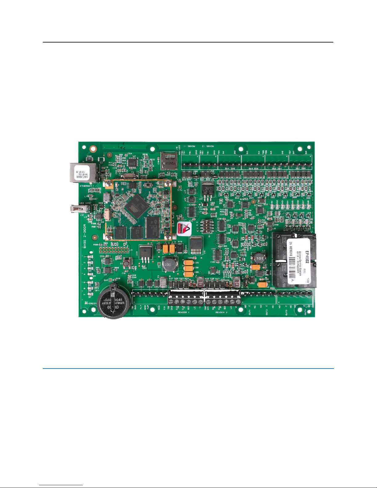
Vanderbilt lite blue Embedded Controller
Overview
The lite blue system is based on a Mercury EP4502 controller and is equipped with 10 / 100 Base-T Ethernet
connection with two RS-485 serial ports and two onboard reader interfaces capable of Wiegand or Magstripe
input. It is a Linux application utilizing an atmel ARM926EJ-S 32-bit processor with 400MHz CPU clock, it also has
a 256MB NAND Flash and 128MB SDRAM. This application can be browsed from any internet connection that will
allow a remote connection to manage the system. lite blue communicates with a series of devices such as the
VBB-RI, VBB-OBRI, VBB-NRI, AD-300, VIP, AD-400 and Wireless readers.
lite blue
Page 20

VLBIM06/15/15 v4.1.0
Chapter 1 lite blue 19
Highlights
8 card reader maximum configuration
8 per RS-485 data channel maximum
2 per onboard Wiegand channels maximum
Each RS-485 channel divided into two sections
Lockable tamper proof enclosure
256MB NAND Flash and 128MB SDRAM with 5,000 ID capability
Dynamically allocated memory
A 8G memory min-SD Card
10/100 Base-T Ethernet Connection
Linux Kernel operating system
Dimensions
lite blue controller: 8" h x 6" w
Enclosure: 12" h x 10" w x 2.75" d
Power: 12/24 VDC
Power Consumption: 250mA
Max. Device Output: 24VDC @100mA (max. 800mA per power input row)
Ambient Temperature: 0C to 49C or 32F to 120F
Humidity: - 85%, +/- 5%
Power Supply Requirements
UL294 Listed Power-Limited Power Supply capable of 4 hours standby power providing 12VDC or 24VDC
Note: The LED on the cover of the VLB is a power indicator. However it is not an AC indicator as the UL Listed
power-limited power supply capable of 4 hour standby power could be providing the VLB with power even if AC
power has been removed.
The lite blue controller is designed to only provide power the power supply to readers attached to the two
onboard reader interfaces. Additional devices must be powered independently from the lite blue controller. If a
single power supply is used, it must be large enough to power the lite blue controller and all attached devices.
Make sure that the total power requirements for all devices does not exceed the output of the power supply(s) in
use (see specific device chapters for power requirements). If not enough power is being supplied, the devices and
the lite blue controller will not work correctly.
Page 21

20 lite blue Installation Manual
Power method 1 - Single Power Supply
In this method a single UL Listed Power Limited power supply is used:
Connect power cables from the power supply to TB1 GND and VIN in order to power lite blue
Connect additional cables from the same power supply to the peripheral devices as needed
Power method 2 - Multiple Power Supplies
In this method multiple UL Listed Power Limited power supplies are used:
Connect one power supply to TB1 GND and VIN to power lite blue
Connect additional power supplies to power peripheral devices as needed
Configuration Guidelines
The lite blue controller has 2 data channels to connect devices via an RS-485 communication protocol and
2 reader interfaces (Channel 0) supporting Wiegand or Magstripe reader heads. Each RS-485 data channel
port can support up to 8 devices. A total of 8 devices for all channels can be connected to lite blue.
lite blue on board reader interfaces will provide power to the connected reader devices. RS-485 devices
must be powered independently.
lite blue allows different types of RS-485 devices (VBB-RI, AD-300, VIP, AD-400 Wireless) to use the
same data channel.
The data connections for every device on the same channel must be properly connected in a daisy chain
and then back to RS458-1 or RS485-2 TR+ and TR-.
A UL Listed Power Limited, Power Supply capable of 4 hours standby power will be needed to provide
power to the external devices.
Please refer to power requirements for each device connecting to lite blue.
Devices must be powered independently of lite blue with a local power source.
Installation and Configuration Steps
1 Mount lite blue controller to wall.
2 Connect all peripheral devices (VBB-RI, VBB-NRI, Wiegand Readers, AD-300, VIP, PIM or PIM-400). See
specific device chapters for details.
3 Connect 12 VDC or 24VDC power supply to TB1 GND and VIN of the lite blue controller.
4 Connect power to all external devices independently as needed.
5 Turn on the power supply to lite blue and any additional power supplies.
6 Configure the lite blue IP address, date and time. See the lite blue IP Configuration and lite blue Date
and Time setup section for details.
Page 22
VLBIM06/15/15 v4.1.0
Chapter 1 lite blue 21
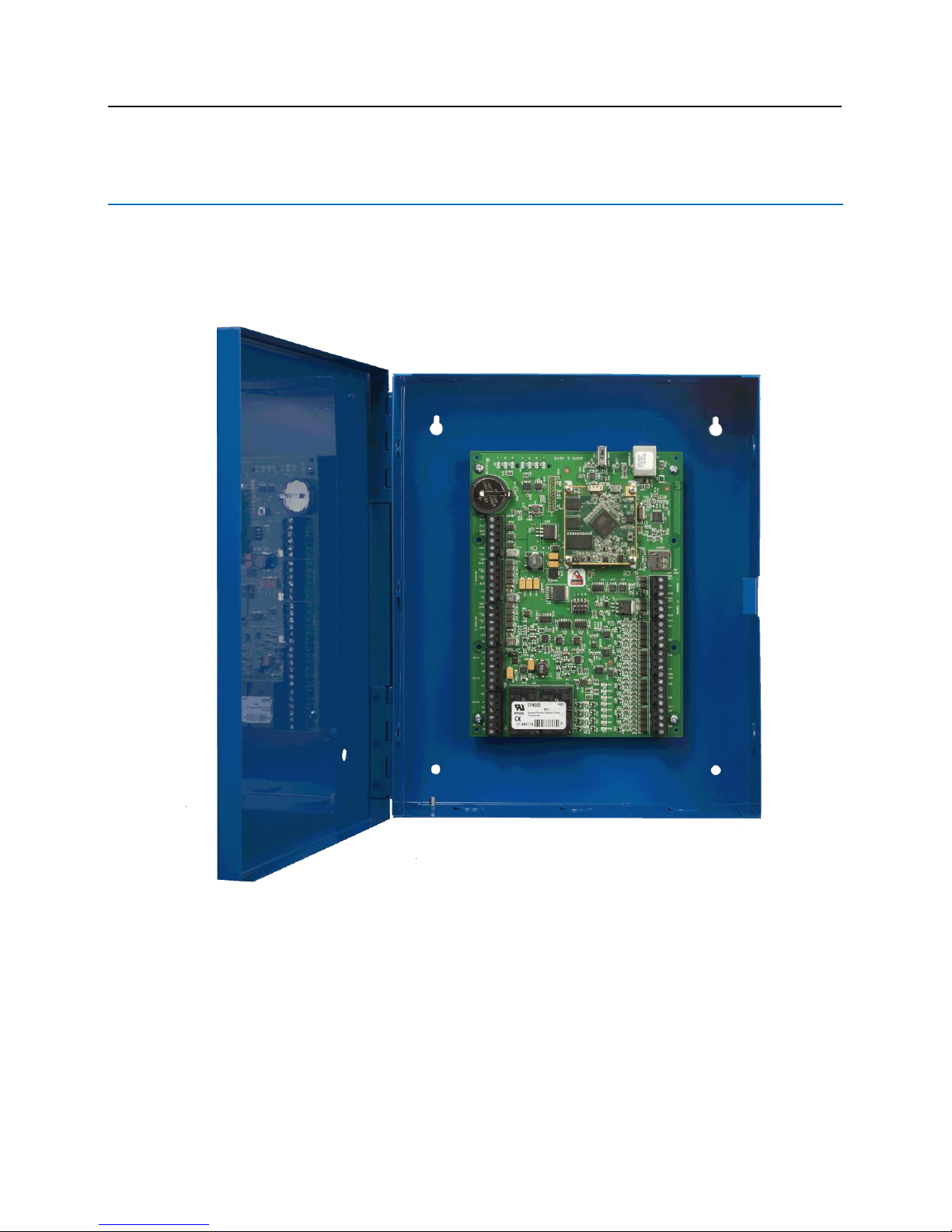
Enclosure Installation
lite blue Enclosure - An enclosure with a hinged door and a lock is included with each lite blue system. The
flying leads of the tamper switch should be attached to a UL Listed burglar alarm system or Listed local
siren/annunciator. Do not connect the flying leads to the tamper switch on lite blue.
Features
Metal enclosure with hinged door
The enclosure is provided with a lock and key
The enclosure is outfitted with a tamper switch
Enclosure Dimensions: 12" x 10" x 2.75"
Page 23
22 lite blue Installation Manual
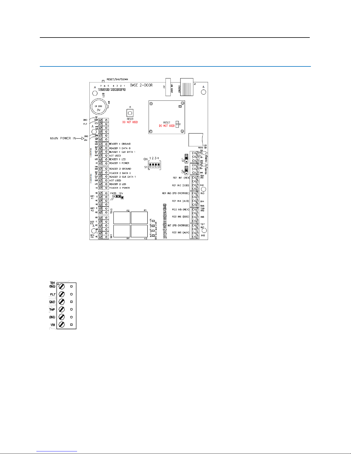
lite blue Pin Layout
lite blue Pin Functions
TB1: Power input for lite blue. 12VDC or 24VDC.
GND (-) Shutdown / Restart
FLT (+) Shutdown / Restart
GND (-) Tamper
TMP (+) Tamper
GND is (-) VLB Main Power
VIN is (+) VLB Main Power
Page 24
VLBIM06/15/15 v4.1.0
Chapter 1 lite blue 23
RESET / SHUTDOWN - Hold for 5 - 9 seconds and release for Reboot.
Hold for 10 seconds for Power Down. Refer to LED Indicators.
Functions On Mercury Controller
J10 - micro SD connection for flash memory.
J12 - USB HOST (reserved for future use).
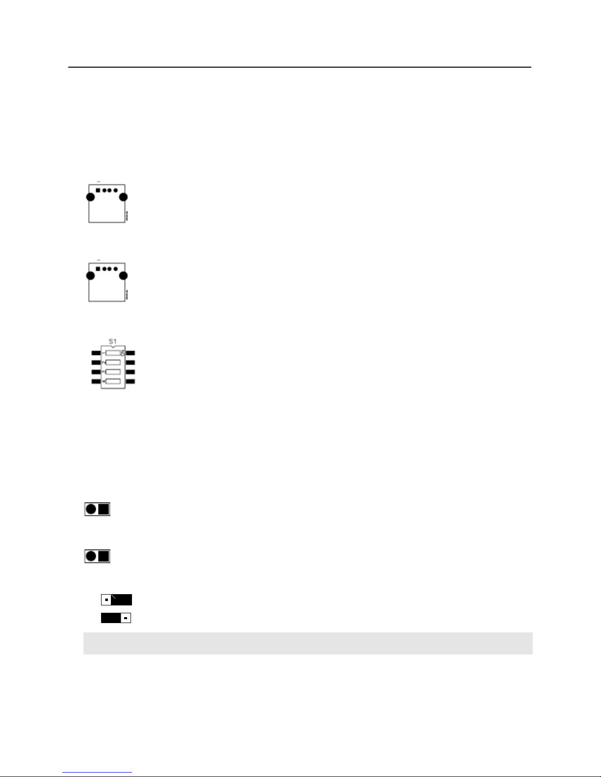
S1 - System Dip Switches
1 - Enable / Disable SSL encryption. ON enables. OFF disables. Default is ON.
2 - SSH Toggle. Default is ON. SSH session available for 10 minutes on System Restart and for 30
minutes after S1-SW2 position changed once disabled.
3 - Not Used.
4 - Not Used.
J5 - RS485 Termination (default = Off)
J9 - RS485 Termination (default = Off)
J7 - PASS 12V = Reader Power Select
12 V Available to Reader Ports (min 20 V in)
Input Power "Passed Through" to Reader Ports
Verify Manufacturer Specifications for Reader Head Voltage Maximum
Page 25

24 lite blue Installation Manual
S2 - RESET -- DO NOT USE.
JP3 [CPU Daughter Board] - DO NOT REMOVE.
J4 [CPU Daughter Board] - RS-232
S1 [CPU Daughter Board] - RESET -- DO NOT USE.
Never Depress the S2 RESET button on the main controller or S1 RESET button on the CPU daughter board.
These buttons will interrupt power to the VLB without shutting down critical software processes and may render
the lite blue system inoperable.
READER 1 - Onboard Reader Interface (Wiegand / Magstripe)
GND
Ground
DAT
D0
Data / Data 0
CLK
D1
Clock / Data 1
BZR
Reader Buzzer
LED
Reader LED
VO
Reader Power
READER 2 - Onboard Reader Interface (Wiegand / Magstripe)
GND
Ground
DAT
D0
Data / Data 0
CLK
D1
Clock / Data 1
BZR
Reader Buzzer
LED
Reader LED
VO
Reader Power
OUT 1 - Relay Output 1 for Reader 1
NO
Normally Open
C
Common
NC
Normally Closed
Page 26

VLBIM06/15/15 v4.1.0
Chapter 1 lite blue 25
OUT 2 - Relay Output 2 for Reader 1
NO
Normally Open
C
Common
NC
Normally Closed
OUT 3 - Relay Output 1 for Reader 2
NO
Normally Open
C
Common
NC
Normally Closed
OUT 4 - Relay Output 2 for Reader 2
NO
Normally Open
C
Common
NC
Normally Closed
IN 1 - Contact Input 1 for Reader 1
2 wires used for Request to Exit (REX)
IN 2 - Contact Input 2 for Reader 1
2 wires used for Door Open Detect (DOD)
IN 3 - Contact Input 3 for Reader 1
2 wires used for Push Button Override
IN 4 - Contact Input 4 for Reader 1
2 wires used for Auxiliary Input
IN 5 - Contact Input 1 for Reader 2
2 wires used for Request to Exit (REX)
IN 6 - Contact Input 2 for Reader 2
2 wires used for Door Open Detect (DOD)
IN 7 - Contact Input 3 for Reader 2
2 wires used for Push Button Override
IN 8 - Contact Input 4 for Reader 2
2 wires used for Auxiliary Input
ETHERNET - Ethernet cable to network connects here.
Page 27

26 lite blue Installation Manual
lite blue LED Indicators
The following table describes the lite blue status information available via the Mercury EP4502 controller LEDs.
ID
Description
D1 CPU
CPU Daughter Board Power
D1
Product Edition:
On = lite blue
Off = bright blue
D2
Not Used (Reserved for future use)
D3
Not Used (Reserved for future use)
D4
Not Used (Reserved for future use)
D5
Not Used (Reserved for future use)
D6
IP Address Configuration:
On = Vanderbilt Default IP (192.168.168.250) assigned
Off = IP Address Changed from Vanderbilt Default
D7
Shutdown / Restart Operation:
Blinking = Button monitoring process active - Normal
Rapid Blinking = Button depressed - Restart on release
Solid = Shutdown Imminent
D8
Not Used (Reserved for future use)
D9
Not Used (Reserved for future use)
D10
Not Used (Reserved for future use)
D11
Not Used (Reserved for future use)
D12
Not Used (Reserved for future use)
D13
Data Transfer Activity:
Blink on data packet transfer between system processes handling GUI /
Database and Door communications
D14
Door Communication Heartbeat
Blink to verify Door communication process active
D15
Not Used (Reserved for future use)
D17
Reader 1 Unlock Relay:
On = Unlock Relay for VBB-OBRI1 Activated
Off = Unlock Relay for VBB-OBRI1 Deactivated
D18
Reader 1 Auxiliary Relay:
On = Auxiliary Relay for VBB-OBRI1 Activated
Off = Auxiliary Relay for VBB-OBRI1 Deactivated
D19
Reader 2 Unlock Relay:
On = Unlock Relay for VBB-OBRI2 Activated
Off = Unlock Relay for VBB-OBRI2 Deactivated
D20
Reader 2 Auxiliary Relay:
On = Auxiliary Relay for VBB-OBRI2 Activated
Off = Auxiliary Relay for VBB-OBRI2 Deactivated
Page 28
VLBIM06/15/15 v4.1.0
Chapter 1 lite blue 27
All Mercury EP4502 controller onboard LED indicators will be turned OFF once the lite blue system has been
safely powered down.
Refer to lite blue Pin Functions above or the User Manual for proper Restart / Shutdown instructions.
lite blue IP Configuration
The IP address of lite blue has to be configured so that it can communicate with a web browser. Configuration
should occur after the controller is fully installed. There are two methods to configure the IP address: Static IP and
DHCP which are detailed below.
Static IP Configuration (Recommended)
1 Connect a PC with a web browser to the lite blue controller.
Direct Connection - Using a cross-over cable, the controller can be connected directly to the network
card of the PC.
Network Connection - Using a regular network cable, the controller can be connected to a hub or switch
that is on the same network as the PC.
2 Configure the PC's network settings to communicate with lite blue.
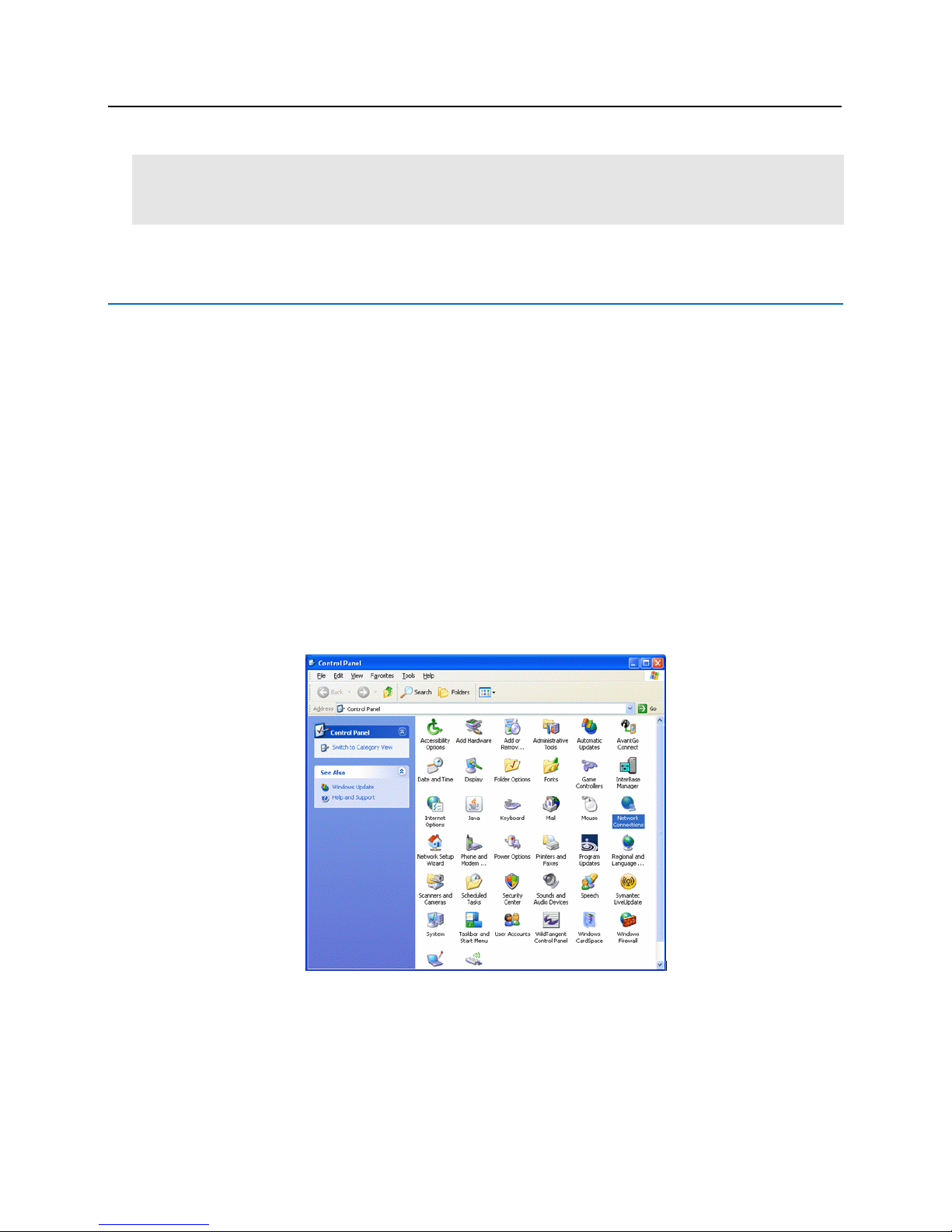
a) Click on the Start button.
b) Click on Control Panel. The Control Panel window will open.
Page 29
28 lite blue Installation Manual
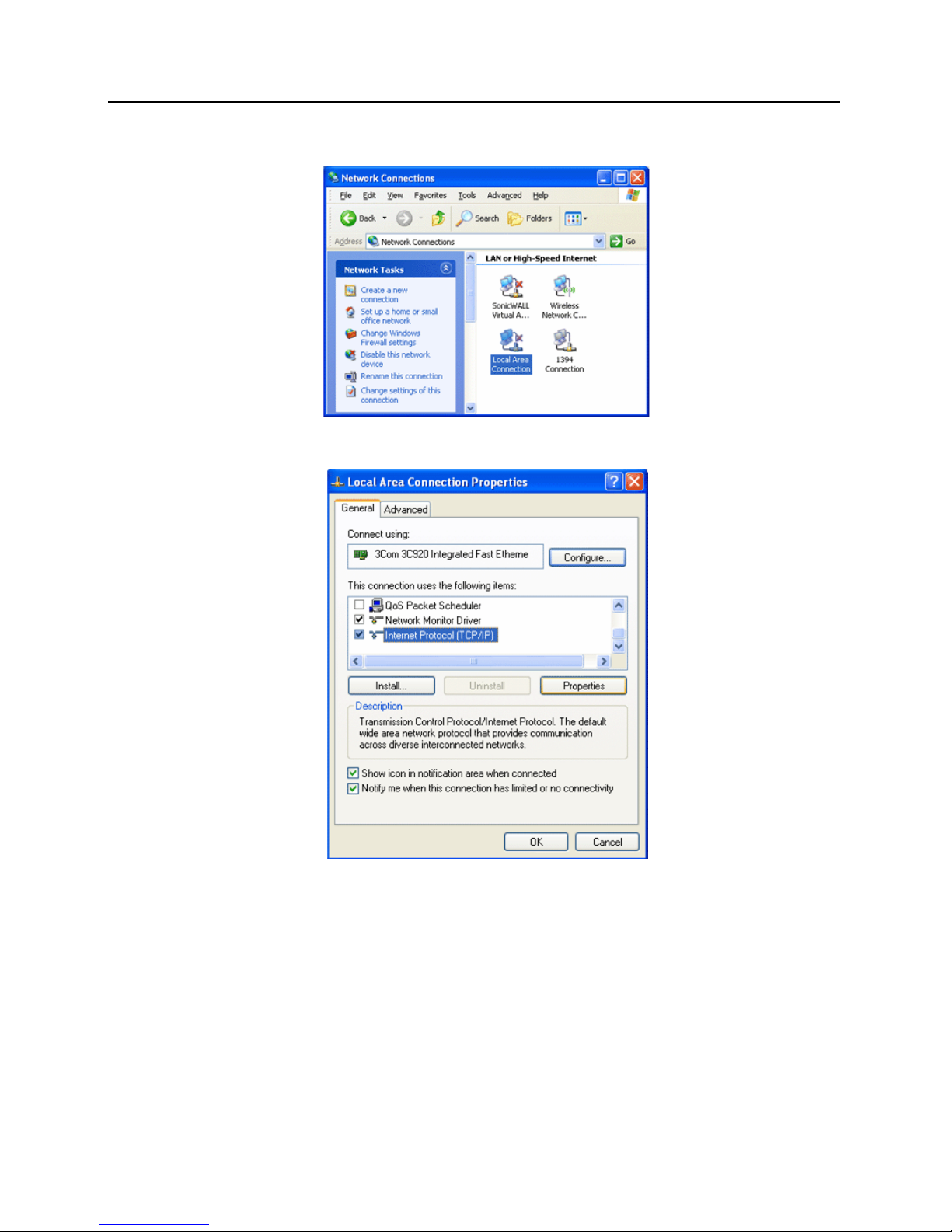
c) Click on Network Connections. The Network Connections window will open.
d) Click on Local Area Connection. The Local Area Connection Properties window will open.
e) Scroll down and select Internet Protocol (TCP/IP).
f) Click the Properties button. The Internet Protocol (TCP/IP) Properties window will open.
Page 30
VLBIM06/15/15 v4.1.0
Chapter 1 lite blue 29
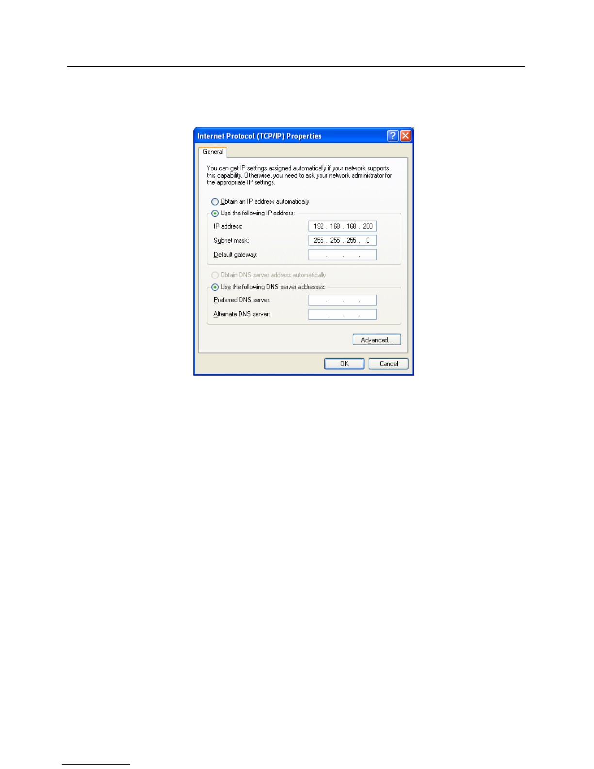
g) Make a note of the existing settings. These will need to be restored at the end of the lite blue
configuration process to return the PC to its usual settings.
h) Click on the Use the following IP address button.
i) Enter 192.168.168.200 into the IP address field.
j) Enter 255.255.255.0 into the Subnet mask field.
k) Click on the OK button. The window will close. The PC's network settings are now compatible with lite
blue.
3 Open a web browser.
4 Go to http://192.168.168.250
Page 31

30 lite blue Installation Manual
a) If dip switch 1 of S1 on the lite blue controller is in the "ON" position then this window will open:
b) This message is not an error and should be bypassed. Click on Continue to this website (not
recommended).
c) The lite blue home page will open. Wait a moment for it to redirect to the log in screen.
5 Log in.
a) Enter User ID. Default User ID is usr.
b) Enter Password. The default password is "password".
Page 32

VLBIM06/15/15 v4.1.0
Chapter 1 lite blue 31
c) Click on the Log In button. The lite blue main window will open.
6 Click on the Utilities button on the left side of the screen. The System Utilities window will open.
Page 33

32 lite blue Installation Manual
7 Click on the View or modify network settings button. The Network Settings window will open.
8 Click on the Static IP button.
a) Enter new IP address into the IP address field. Consult with network technicians to get an address that
is compatible with the existing network.
b) Enter new Subnet mask into the Subnet mask field. Consult with network technicians to get an address
that is compatible with the existing network.
c) Enter new Default gateway into the Default gateway field. Consult with network technicians to get an
address that is compatible with the existing network.
9 Click on the Manually configure DNS server addresses button.
a) Enter a primary DNS server address into the Primary DNS server field. Consult with network
technicians to get an address that is compatible with the existing network.
b) Enter a Secondary DNS server into the Secondary DNS server field. Consult with network technicians
to get an address that is compatible with the existing network.
10 Click on the Save Changes button. The Utilities - Network Settings pop-up window will open.
11 Click on the Continue button. The connection to lite blue will be lost as the network settings are updated.
Page 34

VLBIM06/15/15 v4.1.0
Chapter 1 lite blue 33
12 Close the browser window. A pop-up window will open.
13 Click on the OK button. The pop-up and the browser window will close.
14 Restore the network settings on the PC (follow step 2 above to access the network settings of the PC).
15 Open a web browser.
16 Enter http:// followed by the new IP address into the browser. The lite blue home page will open and lite
blue's IP address is successfully configured.
DHCP Configuration
Configuring the lite blue controller to DHCP requires the Discovery and Configuration program. This program is
located on the CD that is included with lite blue.
To configure the lite blue controller with the Discovery and Configuration tool:
1 Connect the PC running the Discovery and Configuration tool to the lite blue controller.
Direct Connection - Using a cross-over cable, the controller can be connected directly to the network
card of the PC.
Network Connection - Using a regular network cable, the controller can be connected to a hub or switch
that is on the same network as the PC.
Page 35

34 lite blue Installation Manual
2 Run the Discovery and Configuration tool.
3 Click on the On button to search for lite blue controllers.
4 Edit the default values.
a) Select which controller to configure.
b) Click on the Device Configuration button. The Device Configuration window will open.
Page 36

VLBIM06/15/15 v4.1.0
Chapter 1 lite blue 35
c) Click on the Network tab.
d) Using the drop down box, change the IP configuration method to DHCP.
e) Click on the OK button to apply the change.
f) Make a note of the IP Address. Enter the IP address into a web browser to connect to the lite blue
software. It may take a few seconds for the new IP address to be generated.
5 Exit the Discovery and Configuration program.
Note: DHCP is not recommended for lite blue. If the dynamic IP address is changed then the Discovery and
Configuration tool will need to be run to find the new IP address and any bookmarks for lite blue will be
invalidated. Static IP is recommended for lite blue.
lite blue Date and Time Setup
The date and time for lite blue has to be set up for the system to work properly. The date and time can be
entered in two ways: 1) Through the lite blue software. 2) Using the Discovery and Configuration Tool as
described below.
Using the lite blue software to set date and time
1 Connect a PC with a web browser to the lite blue controller.
Direct Connection - Using a cross-over cable, the controller can be connected directly to the network
card of the PC.
Network Connection - Using a regular network cable, the controller can be connected to a hub or switch
that is on the same network as the PC.
2 Open a web browser.
3 Enter the IP address of the lite blue controller into the web browser, see the lite blue IP Configuration
chapter for details.
Page 37

36 lite blue Installation Manual
a) If dip switch 1 of S1 on the lite blue controller is in the "ON" position then this window will open:
s
b) This message is not an error and should be bypassed. Click on Continue to this website (not
recommended).
c) The lite blue home page will open. Wait a moment for it to redirect to the log in screen.
4 Log in.
a) Enter User ID. Default User ID is usr
b) Enter Password. Default Password is password
Page 38

VLBIM06/15/15 v4.1.0
Chapter 1 lite blue 37
c) Click on the Log In button. The lite blue main window will open.
5 Click on the Utilities button on the left of the main screen. The System Utilities window will open.
Page 39

38 lite blue Installation Manual
6 Click on the Set system date, time and time zone button. The Utilities - System Date, Time, and Time
Zone window will open.
7 Set the date, time, and time zone:
a) Using the Time drop down boxes, specify the time.
b) Click on the calendar button to the right of the Date field. The calendar pop-up will open.
c) Select the date. The calendar pop-up will close.
d) Select the time zone from the Regional Time Zone list.
e) Optional: Instead of setting the time and date manually the Sync time with local PC button can be
used. Select the time zone from the Regional Time Zone list and click Save Changes. Then click
on the Sync time with local PC button and the date and time will be synchronized with that of the
PC.
Note: The regional time zone is set to Eastern Time by default.
8 Click on the Apply button. The system time, date, and time zone will be updated.
Using the Discovery and Configuration Tool to set date and time
1 Connect the PC running the Discovery and Configuration tool to the lite blue controller.
Direct Connection - Using a cross-over cable, the controller can be connected directly to the network
card of the PC.
Page 40

VLBIM06/15/15 v4.1.0
Chapter 1 lite blue 39
Network Connection - Using a regular network cable, the controller can be connected to a hub or switch
that is on the same network as the PC.
2 Run the Discovery and Configuration tool.
3 Click on the On button to search for lite blue controllers.
Page 41

40 lite blue Installation Manual
4 Select the lite blue controller and click on the Device Configuration button. The Device Configuration
window will open.
5 Click on the Clock tab.
6 Click on the Set the Clock To button.
7 Click on the Synchronize clock to this computer check box to select it.
8 Click OK to synchronize lite blue with the PC clock.
9 Close the Discovery and Configuration Tool.
Page 42

VLBIM06/15/15 v4.1.0
Chapter 1 lite blue 41
Battery Replacement
The lite blue controller uses a UL Listed Sanyo CR2330 or equivalent 3V Lithium Coin Cell battery. The battery
should be replaced every year.
To replace the battery:
1 Hold the lite blue RESET/SHUTDOWN Switch for at least 10 seconds.
2 After 10 seconds LED D7 will stay on sold and the lite blue will power down within 1 second.
3 Disconnect the lite blue controller from any external power source(s).
4 Disconnect the Ethernet cable.
5 Remove the 3V Lithium Coin Cell battery from the smaller board.
6 Insert a new UL Listed CR2330 3V Lithium Coin Cell battery.
7 Connect the Ethernet cable.
8 Connect power source(s).
9 Set the date and time. See the lite blue Date and Time Setup section for details.
Page 43

42 lite blue Installation Manual
C H A P T E R 2
Reader Interface
Overview
The VBB-RI is a Reader Interface between lite blue and card readers. The VBB-RI offers a cost-effective,
modular approach to access control system design. Reader Interfaces can connect to a variety of different read
head technologies supported by lite blue. These include both Magnetic Stripe (not evaluated by UL) and
Proximity readers.
VBB-RI
Page 44

VLBIM06/15/15 v4.1.0
Chapter 2 VBB-RI 43
Highlights
Supports various read head technologies; Proximity, (Wiegand Format) and Magnetic Stripe (not evaluated
by UL)
Standard 26-bit
Vanderbilt 34-bit
Xceed-ID XF1050 Reader
HID Corporate 1000 35-bit (not evaluated by UL)
HID Corporate 1000 48-bit (not evaluated by UL)
HID/ProxIF 37-Bit
XceedID 40-Bit
Vanderbilt 35-bit (including EV1)
MiFare 32-Bit Serial Number
Communicates via RS-485 protocol
Must be powered locally by an external power supply.
Features
Supports one read-head credential
Connects directly to the communication channels on the lite blue controller via RS-485 protocol
Includes Two 2 amp, form C, single pole/double throw, mechanically latching relay
Connection for one multi-color LED for access granted or access denied indication
Includes 4 input contacts for devices such as exit request (REX), door position switch (DOD), etc.
Specifications
Board Dimensions - 3-13/16” x 3-13/16” x 3/4” D
Enclosure Dimensions - 8-1/4”H x 7-1/2W” x 3-1/2” D
Power requirements - 14 to 24 VDC (usually supplied by lite blue Controller)
Power consumption - 300mA max. (with reader)
Ambient temperature - 0º to 49º C or 32º to 120º F
Page 45

44 lite blue Installation Manual
VBB-RI Enclosure
VBB-RI Enclosure - An enclosure with a hinged door is included for each VBB-RI. The flying leads of the
tamper switch should be attached to a UL Listed burglar alarm system or Listed local siren/annunicator.
Features
Metal enclosure with hinged door
Enclosure Dimensions: 8.25” x 7.5” x 3.5”
Page 46

VLBIM06/15/15 v4.1.0
Chapter 2 VBB-RI 45
Environmental conditions
Ambient Temperature: 0º to 49º C or 32º to 120º F
The room must be dust free and clean.
It is optimal to mount the enclosure on fire rated plywood which is affixed to a cinder block wall or a wall
covering i.e. sheetrock
Mount the cabinet in a secure, but generally accessible location
Mounting the enclosure
Field Wiring - It is recommended that you drill holes or punch the knockouts in the metal enclosure for field
wiring before mounting the enclosure to the wall.
A non-metallic sleeve is recommended to protect the wiring where it enters the cabinet.
Mount the enclosure to the wall using the provided mounting holes. Recommended mounting hardware:
Four 1/4” x 1” lag bolts.
To secure the VBB-RI enclosure use two screws through the openings provided on the cover. Alternately a
lock can be added using the provided punch out section on the cover.
VBB-RI Pin Layout
Page 47

46 lite blue Installation Manual
VBB-RI Pin Functions
P4 - Power source and communication wiring. Used to connect lite blue to the VBB-RI.
Pin 1 is Ground (GND)
Pin 2 is Data B (TXB)
Pin 3 is Data A (RXA)
Pin 4 is Power (14-24V)
P1/P2 - The VBB-RI has four contact points, two at P1 and two at P2. Each contact point has its own ground.
Unsupervised door contacts have maximum wire length of 2,000 feet.
P5/P6 - Relay outputs. The VBB-RI comes with two relay outputs. The relays are single pole/double throw and are
rated at 30 VDC @ 2 amp. P5 is for the Door Held Open relay. P6 is for the door unlock relay.
W1 - Read head voltage selector. The read-head voltage selector provides 5VDC or 12VDC to the various types
of read-heads.
No jumper will provide no power
A jumper across Pins 1 and 2 will also provide 5VDC
A jumper across Pins 2 and 3 will provide 12VDC
Note: Serious damage may occur to the read-head if this jumper is set incorrectly. Please check the read-head
voltage requirements.
W10 - VBB-RI Reader Interface Addressing. The address of the VBB-RI is dependent on the position of jumpers
on these pins. Please see the section on Addressing VBB-RI for more details.
J2 - On Board Tamper Connection. The enclosure tamper switch will be wired to the supplied tamper connector
flying leads. Polarity is not a concern.
DS1 - LED Description.
Slow Blink -- Power, but no data communication
Fast Blink -- Power and data communication
SW1 - Hardware Reset Switch. The Reset Switch clears all the memory on the VBB-RI. Press the reset switch for
3 seconds to clear the memory.
SW2 - Software Reset Switch. Recommended for factory use only.
Note: Make sure that there is power on VBB-RI (P4)
Warning: Do not press switch unless instructed by the factory representative.
Pins Left at Default
The below Pins/Jumpers should be left at their default settings:
W2 - Determines the configuration of the second pin (RXAW1) at P3.
Default: Jumper on pins 1&2
W3 - P3 Pin1/Pin2 RS485 Communication Line Terminator.
Default: No Jumper
Page 48

VLBIM06/15/15 v4.1.0
Chapter 2 VBB-RI 47
W4 - Determines the configuration of the first pin (TXBW0) at P3.
Default: Jumper on pins 5&6
W5 - Determines the configuration of the third pin (RXA) at P4.
Default: Jumper on pins 3&4
W6 - P4 Pin2/Pin3 RS485 Communication Line Terminator.
Default: No Jumper
W7 - Determines the configuration of the second pin (TXB) at P4.
Default: Jumper on pins 1&2
Pins Not Used
W9 - BKDG: No jumper required for normal operation.
Connecting to lite blue
Data communication between the lite blue controller and a VBB-RI reader interface is via RS-485 protocol. Either
RS-485 channel on the lite blue controller can be used to communicate with P4 on a VBB-RI. The below
example is using RS485-1 on the lite blue controller and P4 on the VBB-RI.
Data Communication between lite blue and VBB-RI
lite blue
VBB-RI
Power Supply
RS-485-1 TR+
Pin 3 - RXA (Data A)
RS-485-1 TR-
Pin 2 - TXB (Data B)
Pin 4 - PWR (Power)
+ (Power)
Pin 1 - GND (Ground)
- (Ground)
Page 49

48 lite blue Installation Manual
Powering VBB-RI
The VBB-RI should receive power directly from a UL 294 Listed Power Limited power supply. Power will be
supplied independently from the lite blue controller.
Addressing the VBB-RI
W10 on the VBB-RI consists of four jumpers that can be combined to set the address for the device. Each VBB-RI
on a lite blue controller RS-485 data channel must have a unique address (1 – 8).
Make a note of the address of the VBB-RI and which channel it is connected to. This information will be required to
set up the lock in the software.
VBB-RI Address Chart
VBB-RI Address
Jumper Locations
1
1 2 4 8
2
2 4 8
3
1 4 8
4
4 8 5 1 2 8
6
2 8 7 1 8
8
8
Page 50

VLBIM06/15/15 v4.1.0
Chapter 2 VBB-RI 49
Connecting to Read Head
The VBB-RI reader interface can communicate to many different read heads. Provided here are the pin outs for
the most commonly used read-heads. The connection is different for each reader type. See the Recommended
Wire Chart below for the proper wire type and lengths.
Recommended Wire Chart: VBB-RI to Reader Head
Connection
Maximum
Distance (ft)
Cable Recommendation
VBB-RI to Magstripe Reader Head
200
22 AWG/5 Cond, Strd, Shld
VBB-RI to Proximity Reader Head
500
22 AWG/5 Cond, Strd, Shld
VBB-RI to Door Contact
2000
22 AWG/2 Cond, Strd, Shld
VBB-RI to Exit Button
2000
22 AWG/2 Cond, Strd, Shld
Abbreviations:
Cond. = Conductor
Strd. = Stranded
Shld. = Shielded
P3 - VBB-RI Pin Connections
Page 51

50 lite blue Installation Manual
XCEED ID XF 1050 Proximity Reader
Proximity Read Head Pin Connections
VBB-RI
Proximity Reader
PIN 1 (CLK)
DATA 0 (GREEN)
Pin 2 (DAT)
DATA 1 (WHITE)
Pin 3 (GND)
GROUND (BLACK)
Pin 4 (PWR)
POWER (RED)
Pin 5 (GRN)
LED (ORANGE)
Pin 6 (RED)
NOT USED
Pin 7 (BUZ)
NOT USED
Pin 8 (IBT)
NOT USED
Magnetic Stripe Reader
Magnetic Stripe Read Head Pin Connections
VBB-RI
Magnetic Stripe Reader
PIN 1 (CLK)
DATA 0 (WHITE)
Pin 2 (DAT)
DATA 1 (GREEN)
Pin 3 (GND)
GROUND (BLACK)
Pin 4 (PWR)
POWER (RED)
Pin 5 (GRN)
LED (ORANGE)
Pin 6 (RED)
NOT USED
Pin 7 (BUZ)
NOT USED
Pin 8 (IBT)
NOT USED
Page 52

VLBIM06/15/15 v4.1.0
Chapter 2 VBB-RI 51
Installing Diode for Lock Wiring - Relay
A diode is supplied with the VBB-RI which should be fitted across 12V and COM to protect the relay contacts.
The lock is wired across 12V and COM. A 0V link to COM is then required to complete the circuit. This will be
wired to NO or NC depending on lock type: Fail Open / Fail Closed (diagram above shows Fail Open).
Page 53

52 lite blue Installation Manual
C H A P T E R 3
Onboard Reader Interface
Overview
The VBB-OBRI is an onboard Reader Interface between lite blue and card readers. These 2 included Reader
Interfaces can connect to a variety of different read head technologies supported by lite blue. These include both
Magnetic Stripe (not evaluated by UL) and Proximity readers.
VBB-OBRI
Page 54

VLBIM06/15/15 v4.1.0
Chapter 3 VBB-OBRI 53
Highlights
Supports various read head technologies; Proximity (Wiegand Format) and Magnetic Stripe (not evaluated
by UL)
Standard 26-bit
Vanderbilt 34-bit
Xceed-ID XF1050 Reader
HID Corporate 1000 35-bit (not evaluated by UL)
HID Corporate 1000 48-bit (not evaluated by UL)
HID/ProxIF 37-Bit
XceedID 40-Bit
Vanderbilt 35-bit (including EV1)
MiFare 32-Bit Serial Number
Embedded directly on lite blue Mercury EP4502 Controller
Powered directly from lite blue
Features
Supports one read-head credential
Mounted directly on the lite blue Mercury EP4502 Controller
Includes Two 2 amp, form C, single pole/double throw, mechanically latching relay
Connection for one multi-color LED for access granted or access denied indication
Includes 4 input contacts for devices such as exit request (REX), door position switch (DOD), etc.
Specifications
Power requirements - supplied by lite blue Controller
Power consumption - 300mA max. (with reader)
Ambient temperature - 0º to 49º C or 32º to 120º F
Page 55

54 lite blue Installation Manual
VBB-OBRI Pin Layout
Onboard Reader Interface Connections:
Reader 1 (OUT1, OUT2, IN1, IN2, IN3, IN4)
Reader 2 (OUT3, OUT4, IN5, IN6, IN7, IN8)
Page 56

VLBIM06/15/15 v4.1.0
Chapter 3 VBB-OBRI 55
VBB-OBRI Pin Functions
Reader 1
Reader 1 can be used to connect 1 card-reader to lite blue.
Pin 1 is Ground (GND)
Pin 2 is DAT/D0 (Data 0)
Pin 3 is CLK/D1 (Data 1)
Pin 4 is Buzzer (14-24V)
Pin 5 is LED
Pin 6 is Power (V0)
Reader 1 has four contact points at TB4 - IN1 and TB4 - IN2 and TB5- IN3 and TB5 - IN4. Each contact point has
its own ground. Unsupervised door contacts have maximum wire length of 2,000 feet.
Reader 1 has two relay outputs at TB10 - OUT1 and TB10 - OUT2. The relays are single pole/double throw and
are rated at 30 VDC @ 2 amp. OUT1 is for the Door Unlock relay. OUT2 is for the Door Held Open relay.
Reader 2
Reader 2 can be used to connect 1 card-reader to lite blue.
Pin 1 is Ground (GND)
Pin 2 is DAT/D0 (Data 0)
Pin 3 is CLK/D1 (Data 1)
Pin 4 is Buzzer (14-24V)
Pin 5 is LED
Pin 6 is Power (V0)
Reader 2 has four contact points at TB6 - IN5 and TB6 - IN7 and TB7- IN7 and TB7 - IN8. Each contact point has
its own ground. Unsupervised door contacts have maximum wire length of 2,000 feet.
Reader 2 has two relay outputs at TB11 - OUT3 and TB11 - OUT4. The relays are single pole/double throw and
are rated at 30 VDC @ 2 amp. OUT3 is for the Door Unlock relay. OUT4 is for the Door Held Open relay.
J7 - Read head voltage selector. The read-head voltage selector provides pass-through or 12VDC to the various
types of read-heads for both Reader 1 and Reader 2.
No jumper will provide no power
A jumper across Pass and the center Pin will pass-through VLB main input voltage
A jumper across the center Pin and 12V will provide 12VDC
Note: Serious damage may occur to the read-head if this jumper is set incorrectly. Please check the read-head
voltage requirements.
Page 57

56 lite blue Installation Manual
Connecting to lite blue
The VBB-OBRI are mounted onboard the VLB Mercury EP4502 Controller. No additional connection to lite blue
is required.
Addressing the VBB-OBRI
The two VBB-OBRI readers are addressed using the lite blue software. Please refer to the lite blue User Manual
under Door Setup.
Connecting to Read Head
The VBB-OBRI reader interface can communicate to many different read heads. Provided here are the pin outs for
the most commonly used read-heads. The connection is different for each reader type. See the Recommended
Wire Chart below for the proper wire type and lengths.
Recommended Wire Chart: VBB-OBRI to Reader Head
Connection
Maximum
Distance (ft)
Cable Recommendation
VBB-OBRI to Magstripe Reader Head
200
22 AWG/5 Cond, Strd, Shld
VBB-OBRI to Proximity Reader Head
500
22 AWG/5 Cond, Strd, Shld
VBB-OBRI to Door Contact
2000
22 AWG/2 Cond, Strd, Shld
VBB-OBRI to Exit Button
2000
22 AWG/2 Cond, Strd, Shld
Abbreviations:
Cond. = Conductor
Strd. = Stranded
Shld. = Shielded
Page 58

VLBIM06/15/15 v4.1.0
Chapter 3 VBB-OBRI 57
VBB-OBRI Pin Connections
XCEED ID XF 1050 Proximity Reader
Proximity Read Head Pin Connections
VBB-OBRI
Proximity Reader
PIN 1 (GND)
GROUND (BLACK)
PIN 2 (DAT/D0)
DATA 0 (GREEN)
PIN 3 (CLK/D1)
DATA 1 (WHITE)
PIN 4 (BZR)
NOT USED
PIN 5 (LED)
LED (ORANGE)
PIN 6 (VO)
POWER (RED)
Magnetic Stripe Reader
Magnetic Stripe Read Head Pin Connections
VBB-OBRI
Magnetic Stripe Reader
PIN 1 (GND)
GROUND (BLACK)
PIN 2 (DAT/D0)
DATA 0 (WHITE)
PIN 3 (CLK/D1)
DATA 1 (GREEN)
PIN 4 (BZR)
NOT USED
PIN 5 (LED)
LED (ORANGE)
PIN 6 (V0)
POWER (RED)
Page 59

58 lite blue Installation Manual
C H A P T E R 4
lite blue Reader Interface (SBB-RI Legacy)
Overview
The Legacy SBB-RI is a Reader Interface between lite blue and card readers. The SBB-RI offers a cost-effective,
modular approach to access control system design. Reader Interfaces can connect to a variety of different read
head technologies supported by lite blue. These include both Magnetic Stripe (not evaluated by UL) and
Proximity readers.
SBB-RI (Legacy)
Page 60

VLBIM06/15/15 v4.1.0
Chapter 4 SBB-RI (Legacy) 59
Highlights
Supports various read head technologies; Proximity, (Wiegand Format) and Magnetic Stripe (not evaluated
by UL)
Standard 26-bit
Vanderbilt 34-bit
Xceed-ID XF1050 Reader
HID Corporate 1000 35-bit (not evaluated by UL)
HID Corporate 1000 48-bit (not evaluated by UL)
HID/ProxIF 37-Bit
XceedID 40-Bit
Vanderbilt 35-bit (including EV1)
MiFare 32-Bit Serial Number
Communicates via RS-485 protocol
Must be powered locally by an external power supply.
Standard Features
Supports one read-head credential
Connects directly to the communication channels on the lite blue controller via RS-485 protocol
Includes Two 2 amp, form C, single pole/double throw, mechanically latching relay
Connection for one multi-color LED for access granted or access denied indication
Includes 4 input contacts for devices such as exit request (REX), door position switch (DOD), etc.
Specifications
Board Dimensions - 3-13/16” x 3-13/16” x 1-3/4”D
Enclosure Dimensions - 8-1/4”H x 7-1/2W” x 3-1/2”D
Power requirements - 12 to 24 VDC (supplied by lite blue controller)
Power consumption - 300mA max. (with reader)
Ambient temperature - 0º to 49º C or 32º to 120º F
Page 61

60 lite blue Installation Manual
SBB-RI Enclosure
SBB-RI Enclosure - An enclosure with a hinged door is included for each SBB-RI. The flying leads of the
tamper switch should be attached to a UL Listed burglar alarm system or Listed local siren/annunicator.
Features
Metal enclosure with hinged door
Enclosure Dimensions: 8.25” x 7.5” x 3.5”
Environmental conditions
Ambient Temperature: 0º to 49º C or 32º to 120º F
The room must be dust free and clean.
It is optimal to mount the enclosure on fire rated plywood which is affixed to a cinder block wall or a wall
covering i.e. sheetrock
Mount the cabinet in a secure, but generally accessible location
Mounting
Field Wiring - It is necessary to punch the knockouts in the metal enclosure for field wiring. It is
recommended that this is done before mounting the enclosure to the wall.
A non-metallic sleeve is recommended to protect the wiring where it enters the cabinet.
Mount the enclosure to the wall using the provided mounting holes. Recommended mounting hardware:
Four 1/4” x 1” lag bolts.
To secure the SBB-RI enclosure use two screws through the openings provided on the cover. Alternately a
lock can be added using the provided punch out section on the cover.
Page 62

VLBIM06/15/15 v4.1.0
Chapter 4 SBB-RI (Legacy) 61
SBB-RI Pin Layout
SBB-RI Pin Functions
P4 - Power source and communication wiring. Used to connect lite blue to the SBB-RI.
Page 63

62 lite blue Installation Manual
Pin 4 is Ground
Pin 3 is Data B
Pin 2 is Data A
Pin 1 is Power
P1 - Contact Inputs. The SBB-RI has four unsupervised contact points. When connecting more than two contact
inputs to Pin 8 (GND), a terminal strip to connect the common ground wires needs to be installed. Unsupervised
door contacts have maximum wire length of 2,000 feet.
Pin 1 is Exit Request (REX) - Normally Open
Pin 2 is Door Position Switch (DOD) - Normally Closed
Pin 3 is Push Button Override - Normally Open
Pin 4 is Auxiliary Input - Normally Closed
Pin 5 is Not Used
Pin 5 is Not Used
Pin 6 is Not Used
Pin 7 is Not Used
Pin 8 is Ground
P5/P6 - Relay outputs. The SBB-RI comes with two relay output. The relays are single pole/double throw and are
rated at 30 VDC @ 2 amp.
Pin 1 - Normally Open
Pin 2 - Normally Closed
Pin 3 - Common
W5 - Factory use only. Do not add a jumper under normal operating conditions.
W3 - Read head voltage selector. The SBB-RI read-head voltage selector provides 5VDC or 12VDC to the
various types of read-heads depending on jumper location.
No jumper will provide 5VDC
A jumper across Pins 1 and 2 will also provide 5VDC
A jumper across Pins 2 and 3 will provide 12VDC
Warning: Serious damage may occur to the read-head if this jumper is set incorrectly. Please check the read-
head voltage requirements.
W2 - SBB-RI addressing. The address of the SBB-RI is dependent on the position of jumpers on these pins.
Please see the section on Addressing SBB-RI for more details.
Page 64

VLBIM06/15/15 v4.1.0
Chapter 4 SBB-RI (Legacy) 63
Connecting to lite blue
Data communication between the lite blue controller and a VBB-RI reader interface is via RS-485 protocol. Either
RS-485 channel on the lite blue controller can be used to communicate with P4 on a VBB-RI. The below
example is using RS485-1 on the lite blue controller and P4 on the VBB-RI.
Data Communication between lite blue and SBB-RI
lite blue
SBB-RI
Power Supply
RS-485-1 TR+
Pin 2 - RXDA (Data A)
RS-485-1 TR-
Pin 3 - TXDB (Data B)
Pin 1 - PWR (Power)
+ (Power)
Pin 4 - GND (Ground)
- (Ground)
Powering SBB-RI
The SBB-RI should receive power directly from a UL 294 Listed Power Limited power supply. Power will be
supplied independently from the lite blue controller.
Page 65

64 lite blue Installation Manual
Addressing the SBB-RI
W2 on the SBB-RI consists of four jumpers that can be combined to set the address for the device. Each SBB-RI
on a lite blue controller RS-485 data channel must have a unique address (1 – 8).
Make a note of the address of the SBB-RI and which channel it is connected to. This information will be required to
set up the lock in the software.
SBB-RI Address Chart
SBB-RI Address
Jumper Locations
1
1 2 4 8
2
2 4 8
3
1 4 8
4
4 8 5 1 2 8
6
2 8
7
1 8
8
8
Connecting to Read Head
The SBB-RI reader interface can communicate to many different read heads. Provided here are the pin outs for
the most commonly used read-heads. The connection is different for each reader type. See the Recommended
Wire Chart below for the proper wire type and lengths.
Recommended Wire Chart: SBB-RI to Reader Head
Connection
Maximum
Distance (ft)
Cable Recommendation
SBB-RI to Magstripe Reader Head
200
22 AWG/5 Cond, Strd, Shld
SBB-RI to Proximity Reader Head
500
22 AWG/5 Cond, Strd, Shld
SBB-RI to Door Contact
2000
22 AWG/2 Cond, Strd, Shld
SBB-RI to Exit Button
2000
22 AWG/2 Cond, Strd, Shld
Abbreviations:
Cond. = Conductor
Strd. = Stranded
Shld. = Shielded
Page 66

VLBIM06/15/15 v4.1.0
Chapter 4 SBB-RI (Legacy) 65
P3 - SBB-RI pin connections
XCEED ID XF 1050 Proximity Reader
Page 67

66 lite blue Installation Manual
Proximity Read Head Pin Connections
SBB-RI
Proximity Reader
PIN 1 (CLK)
DATA 0 (GREEN)
Pin 2 (DAT)
DATA 1 (WHITE)
Pin 3 (GND)
GROUND (BLACK)
Pin 4 (PWR)
POWER (RED)
Pin 5 (GRN)
LED (ORANGE)
Pin 6 (RED)
NOT USED
Pin 7 (BUZ)
NOT USED
Magnetic Stripe Reader
Magnetic Stripe Read Head Pin Connections
SBB-RI
Magnetic Stripe Reader
PIN 1 (CLK)
DATA 0 (WHITE)
Pin 2 (DAT)
DATA 1 (GREEN)
Pin 3 (GND)
GROUND (BLACK)
Pin 4 (PWR)
POWER (RED)
Pin 5 (GRN)
LED (ORANGE)
Pin 6 (RED)
NOT USED
Pin 7 (BUZ)
NOT USED
Page 68

VLBIM06/15/15 v4.1.0
Chapter 5 VBB-NRI 67
C H A P T E R 5
Vanderbilt bright blue Network Reader Interface (VBB-NRI)
Overview
The VBB-NRI is a Networked Reader Interface that communicates with lite blue via a network connection. The
VBB-NRI offers a cost-effective, modular approach to access control system design. Networked Reader Interfaces
can connect to a variety of different read head technologies supported by lite blue. These include both Magnetic
Stripe and Proximity readers.
VBB-NRI
Page 69

68 lite blue Installation Manual
Highlights
Supports various read head technologies; Proximity, (Wiegand Format) and Magnetic Stripe
Standard 26-bit
Vanderbilt 34-bit
Xceed-ID XF1050 Reader
HID Corporate 1000 35-Bit (not evaluated by UL)
HID Corporate 1000 48-Bit (not evaluated by UL)
HID/ProxIF 37-Bit
XceedID 40-Bit
Vanderbilt 35-bit (including EV1)
MiFare 32-Bit Serial Number
Communicates via network protocol at 10Base-T
Powered locally by a UL294 Listed Power-Limited, Power Supply capable of 4 hours standby power.
OPTIONAL - can be powered directly from lite blue. (See Cable Requirement Chart for details)
Standard Features
Supports one read-head credential
Communicates with lite blue via network protocol at 10/100 Base-T
Connection for one multi-color LED for access granted or access denied indication
Includes 4 input contacts for devices such as exit request (REX), door position switch (DOD), etc.
Specifications
Board Dimensions - 3-13/16” x 3-13/16” x 2-1/4”D
Enclosure Dimensions - 8-1/4”H x 7-1/2W” x 3-1/2”D
Power requirements - 20VDC to 32VDC
Power consumption - 300mA max. with reader
Ambient temperature - 0º to 49º C or 32º to 120º F
VBB-NRI Enclosure
VBB-NRI Enclosure - An enclosure with a hinged door is included for each VBB-NRI.
Features
Metal enclosure with hinged door
Enclosure Dimensions: 8.25” x 7.5” x 3.5”
Page 70

VLBIM06/15/15 v4.1.0
Chapter 5 VBB-NRI 69
Environmental conditions
Ambient Temperature: 0º to 49º C or 32º to 120º F
The room must be dust free and clean.
It is optimal to mount the enclosure on fire rated plywood which is affixed to a cinder block wall or a wall
covering i.e. sheetrock
Mount the cabinet in a secure, but generally accessible location
Mounting
Field Wiring - It is necessary to punch the knockouts in the metal enclosure for field wiring. It is
recommended that this is done before mounting the enclosure to the wall.
A non-metallic sleeve is recommended to protect the wiring where it enters the cabinet.
Mount the enclosure to the wall using the provided mounting holes. Recommended mounting hardware:
Four 1/4” x 1” lag bolts.
To secure the VBB-NRI enclosure use two screws through the openings provided on the cover. Alternately
a lock can be added using the provided punch out section on the cover.
VBB-NRI IP Configuration
The IP address of the VBB-NRI has to be configured so that it can communicate with lite blue. Configuration
should occur after the reader interface is fully installed. There are two methods to configure the IP address: Static
IP and DHCP which are detailed below.
Note: Communication is at 10Base-T
Static IP Configuration (Recommended)
1 Connect a PC with a web browser to the VBB-NRI.
Direct Connection - Using a cross-over cable, the reader interface can be connected directly to the
network card of the PC.
Network Connection - Using a regular network cable, the reader interface can be connected to a hub or
switch that is on the same network as the PC.
Page 71

70 lite blue Installation Manual
2 Configure the PC's network settings to communicate with the VBB-NRI
a) Click on the Start button.
b) Click on Control Panel. The Control Panel window will open.
c) Click on Network Connections. The Network Connections window will open.
Page 72

VLBIM06/15/15 v4.1.0
Chapter 5 VBB-NRI 71
d) Click on Local Area Connection. The Local Area Connection Properties window will open.
e) Scroll down and select Internet Protocol (TCP/IP).
f) Click the Properties button. The Internet Protocol (TCP/IP) Properties window will open.
g) Make a note of the existing settings. These will need to be restored at the end of the VBB-NRI
configuration process to return the PC to its usual settings.
Page 73

72 lite blue Installation Manual
h) Click on the Use the following IP address button.
i) Enter 192.168.168.200 into the IP address field.
j) Enter 255.255.255.0 into the Subnet mask field.
k) Click on the OK button. The PC's network settings are now compatible with the default VBB-NRI.
3 Open a web browser.
4 Go to http://192.168.168.249 The SRI IP Configuration window will open.
Page 74

VLBIM06/15/15 v4.1.0
Chapter 5 VBB-NRI 73
5 Click on the Display button, the VBB-NRI IP Configuration GUI window will open. See the Configuration
GUI section for additional details.
6 Click on the Static IP button.
a) Enter new IP address into the IP address field. Consult with network technicians to get an address that
is compatible with the existing network.
b) Enter new Subnet mask into the Subnet mask field. Consult with network technicians to get an address
that is compatible with the existing network.
c) Enter new Default gateway into the Default gateway field. Consult with network technicians to get an
address that is compatible with the existing network.
7 Click on the Manually configure DNS server addresses button.
a) Enter a primary DNS server address into the Primary DNS server field. Consult with network technicians
to get an address that is compatible with the existing network.
b) Enter a Secondary DNS server into the Secondary DNS server field. Consult with network technicians to
get an address that is compatible with the existing network.
8 Click on the Update button. Make a note of the IP address as it will be used in the lite blue Door Setup
section.
9 Restore the network settings on the PC (follow step 2 above to access the network settings of the PC).
Page 75

74 lite blue Installation Manual
The Static IP address of the VBB-NRI has been set.
Note: The Static IP address can also be set using the Discovery and Configuration Tool. Follow the directions
below for DHCP but select the Static IP configuration option and manually enter the IP address and Subnet mask.
DHCP Configuration
Configuring the VBB-NRI to DHCP requires the Discovery and Configuration program (located on the CD that is
included with lite blue).
To configure the VBB-NRI with the Discovery and Configuration tool:
1 Connect the PC running the Discovery and Configuration tool to the VBB-NRI.
Direct Connection - Using a cross-over cable, the VBB-NRI can be connected directly to the network
card of the PC.
Network Connection - Using a regular network cable, the VBB-NRI can be connected to a hub or switch
that is on the same network as the PC.
2 Run the Discovery and Configuration tool.
Page 76

VLBIM06/15/15 v4.1.0
Chapter 5 VBB-NRI 75
3 Click on the On button to search for VBB-NRI.
4 Edit the default values.
a) Select which VBB-NRI to configure. If multiple VBB-NRIs are discovered, use the Serial Number to
determine which to configure.
b) Click on the Device Configuration button to open the Device Configuration window.
c) Click on the Network tab.
d) Using the drop down box, change the IP configuration method to DHCP.
e) Click on the OK button to apply the change.
Page 77

76 lite blue Installation Manual
f) Make a note of the IP Address, it will be used by the lite blue interface to configure the VBB-NRI.
5 Exit the Discovery and Configuration program.
The DHCP address of the VBB-NRI has been set.
Note: The DHCP address can also be set using the Configuration GUI. Follow the directions above for Static IP
but select the DHCP configuration option and then use the Discovery and Configuration tool to find the IP address.
Configuration GUI (Graphic User Interface)
Hostname - This displays the name of the specific VBB-NRI board. The default name should not be changed.
The name is in a standard format of SRI-01-XXX.
SRI - Smart Reader Interface
01 - The designation for an VBB-NRI
XXX - The serial number of the specific VBB-NRI (in the above example the serial number is 975).
Page 78

VLBIM06/15/15 v4.1.0
Chapter 5 VBB-NRI 77
The Host Name is used to access and setup the VBB-NRI using Dynamic DNS in conjunction with DHCP. Consult
with network technicians for details on setting up your network in this manner.
DHCP - This setting sets up the VBB-NRI to use a DHCP server on your network (use only if you have a DHCP
server on the network).
Static - This setting forces the VBB-NRI to use a static IP address.
IP Address
When in Static mode, this is where you set the NRI's IP address.
When in DHCP mode, displays the IP address configured by the DHCP server.
Subnet Mask
When in Static mode, this is where you set the NRI's subnet mask.
When in DHCP mode, displays the subnet mask configured by the DHCP server.
Default Gateway
When in Static mode, this is where you set the default gateway.
When in DHCP mode, displays the default gateway configured by the DHCP server.
Obtain DNS Server Address Automatically - When chosen, your DHCP server will assign your DNS Server
IP addresses.
Manually Configure DNS Server Address - When chosen you will assign your DNS server IP addresses.
Primary DNS
When Automatically obtained, displays the Primary DNS chosen by the DHCP server.
When Manually entered, this is where you enter the Primary DNS address.
Secondary DNS
When Automatically obtained, displays the Secondary DNS chosen by the DHCP server.
When Manually entered, this is where you enter the Secondary DNS address.
Enable Ether Link Auto Negotiation - The VBB-NRI is capable of communication speeds of either 10 or 100
Base-T and, with this option enabled, can switch between the two speeds if necessary. Enabled this option to
allow the VBB-NRI to automatically detect and use the communication speed of the switch it is connected to.
NRI Lock (Relay 1) Configuration - This section is used to define the state of Relay 1 on the VBB-NRI in
case of network communication failure during MRO Override state or power restored without network
communications restoration.
Note: Whether the lock connected to the VBB-NRI is Fail Safe or Fail Secure will ultimately determine what effect
the state of Relay 1 will have on the lock. The examples below are assuming a Fail Secure installation.
Comm Failure - Choose one of the options to define the behaviour of Relay 1 in the event of
communication failure. Once communication is returned Relay 1 will resume its Normal Operation state.
Retain State - The lock will stay in whatever state it was in (activated or deactivated) when
communication was lost.
Unlocked - The relay will be activated when communication is lost. In most installations this will mean
that the door will become unsecured.
Page 79

78 lite blue Installation Manual
Locked - The relay will be deactivated when communication is lost. In most installations this will mean
that the door will become secured.
Power On - This section is used to define the behaviour of Relay 1 while lite blue is reloading the VBB-
NRI after a power loss. In the case of a power failure Relay 1 will become deactivated. When power and
communication are returned, lite blue will need to reload the VBB-NRI. During this time the Power On
option determines what state Relay 1 will be in. Once the VBB-NRI has been fully restored it will resume its
Normal Operation state.
Unlocked - The relay will be activated when the VBB-NRI receives power and is being reloaded. In
most installations this will mean that the door will become unsecured.
Locked - The relay will be deactivated when the VBB-NRI receives power and is being reloaded. In
most installations this will mean that the door will become secured.
VBB-NRI Pin Layout
Page 80

VLBIM06/15/15 v4.1.0
Chapter 5 VBB-NRI 79
VBB-NRI Pin Functions
P1 - Power source wiring. Used to supply power to the VBB-NRI.
Pin 1 is Ground
Pin 2 is RXA and is not used with lite blue
Pin 3 is TXB and is not used with lite blue
Pin 4 is Power
P2 - Read head connection.
Pin 1 through 5 are used to connect to a read head. See the Connecting to Read Head section for
details.
Pin 6 is RED and is not used with lite blue
Pin 7 is IBT and is not used with lite blue
P3 - Contact Inputs. The VBB-NRI has four unsupervised contact points. When connecting more than two contact
inputs to Pin 5 (GND), a terminal strip to connect the common ground wires needs to be installed. Unsupervised
door contacts have maximum wire length of 2,000 feet.
Pin 1 is Exit Request (REX) - Normally Open
Pin 2 is Door Position Switch (DOD) - Normally Closed
Pin 3 is Push Button Override - Normally Open
Pin 4 is Auxiliary Input - Normally Closed
Pin 5 is Ground
P5/P6 - Relay outputs. The VBB-NRI comes with two relay output.
Pin 1 - Normally Open
Pin 2 - Normally Closed
Pin 3 - Common
W4 - Read head voltage selector. The VBB-NRI read-head voltage selector provides 5VDC or 12VDC to the
various types of read-heads depending on jumper location.
A jumper across Pins 1 and 2 will provide 12VDC (Default Setting)
A jumper across Pins 2 and 3 will provide 5VDC
No jumper will also provide 5VDC
Warning: Serious damage may occur to the read-head if this jumper is set incorrectly. Please check the read-
head voltage requirements.
W9 - Used to disable network functionality. This pin functions differently depending on which version of the VBBNRI is in use. See the Verifying Upgrade/Checking Version Number section at the end of this chapter if
you need to determine which version of the VBB-NRI is in use.
VBB-NRI versions 11 and below:
Pins 1&2 - Enable/Disable onboard web server (Configuration GUI). Enabled by default. If jumpered
together, the onboard web server is disabled.
Page 81

80 lite blue Installation Manual
Pins 3&4 - Enable/Disable Telnet. Enabled by default. If jumpered together, Telnet is disabled
Pins 5&6 - Enable/Disable Discovery protocol. Enabled by default. If jumpered together, the Discovery
protocol is disabled, meaning that the Discovery tool will NOT find the unit.
Pins 7&8 - reserved for future use.
VBB-NRI version 12 and above:
Pins 1 & 2 - Enable/Disable: Onboard web server (Configuration GUI), Telnet, Ping and Discovery
protocol. Enabled by default. If jumpered together, the onboard web server (GUI), Telnet, Ping and
Discovery protocol are disabled. If disabled then the VBB-NRI cannot be reached via the GUI, Telnet,
Ping or the Discovery and Configuration Tool.
Pins 3 & 4 - Not used at this time.
Pins 5 & 6 - Not used at this time.
Pins 7 & 8 - Not used at this time.
Warning: After installation it is recommended that both the onboard web server and telnet be disabled.
Leaving them enabled could allow unauthorized access to the VBB-NRI.
Pins Left at Default
The below pins should be left at their default settings:
W1/W3 - Used to set the Host communication protocol. Default W1: 1&2 Default W3: 2&3
W2 - Used for RS485 termination (Reader Interface Termination). Default: 2&3
W5/W7 - Sets communication protocol. Default W5: 5&6 Default W7 1&2
W6 - Used for RS485 termination (Controller Board Termination). Default 2&3
W8 - Used to set Magstripe data signal for negative or positive. Default 1&2
Pins Not Used
The below pins are not used on the VBB-NRI:
P4
P7
Page 82

VLBIM06/15/15 v4.1.0
Chapter 5 VBB-NRI 81
Connecting to lite blue
There is no direct connection between the VBB-NRI and lite blue. They need to be on the same network and the
proper IP address of the VBB-NRI needs to be entered when setting up the door (see the VBB-NRI IP
Configuration section for details) for them to communicate. In addition, a data surge protector needs to be installed
between lite blue and the hub or switch. Install the supplied data surge protector (DITEK-DTK-MRJ45C5E) or an
equivalent UL Listed unit. Power is supplied independently from a power supply connecting to P1 on the VBB-NRI.
Data Communication between lite blue and VBB-NRI
lite blue
VBB-NRI
Power Supply
Ethernet To Network
Ethernet to Network
Pin 1 - PWR (Power)
+ (Power)
Pin 4 - GND (Ground)
- (Ground)
Page 83

82 lite blue Installation Manual
Connecting to Read Head
The VBB-NRI reader interface can communicate to many different read heads. Provided here are the pin outs for
the most commonly used read-heads. The connection is different for each reader type. See the Recommended
Wire Chart below for the proper wire type and lengths.
Recommended Wire Chart: VBB-NRI to Reader Head
Connection
Maximum
Distance (ft)
Cable Recommendation
VBB-NRI to Magstripe Reader Head
200
22 AWG/5 Cond, Strd, Shld
VBB-NRI to Proximity Reader Head
500
22 AWG/5 Cond, Strd, Shld
VBB-NRI to Door Contact
2000
22 AWG/2 Cond, Strd, Shld
VBB-NRI to Exit Button
2000
22 AWG/2 Cond, Strd, Shld
Abbreviations:
Cond. = Conductor
Strd. = Stranded
Shld. = Shielded
P2 - VBB-NRI pin connections
Page 84

VLBIM06/15/15 v4.1.0
Chapter 5 VBB-NRI 83
Proximity Reader
Proximity Read Head Pin Connections
VBB-NRI
Proximity Reader
PIN 1 (CLK)
DATA 0 (GREEN)
Pin 2 (DAT)
DATA 1 (WHITE)
Pin 3 (GND)
GROUND (BLACK)
Pin 4 (PWR)
POWER (RED)
Pin 5 (GRN)
LED (ORANGE)
Pin 6 (RED)
NOT USED
Pin 7 (IBT)
NOT USED
Magnetic Stripe Reader
Magnetic Stripe Read Head Pin Connections
VBB-NRI
Magnetic Stripe Reader
PIN 1 (CLK)
DATA 0 (WHITE)
Pin 2 (DAT)
DATA 1 (GREEN)
Pin 3 (GND)
GROUND (BLACK)
Pin 4 (PWR)
POWER (RED)
Pin 5 (GRN)
LED (ORANGE)
Pin 6 (RED)
NOT USED
Pin 7 (IBT)
NOT USED
Page 85

84 lite blue Installation Manual
Installing Diode for Lock Wiring - Relay
A diode is supplied with the VBB-NRI which should be fitted across 12V and COM to protect the relay contacts.
The lock is wired across 12V and COM. A 0V link to COM is then required to complete the circuit. This will be
wired to NO or NC depending on lock type: Fail Open / Fail Closed (diagram above shows Fail Open).
Upgrading Firmware
With v10 and higher of the VBB-NRI it is possible for the user to update the firmware using the TFTP update
through a telnet session.
To update the firmware:
1 Open the command line.
2 Navigate to the location of the update file.
3 Enter tftp –i "VBB-NRI IP Address" put "filename";
Page 86

VLBIM06/15/15 v4.1.0
Chapter 5 VBB-NRI 85
Example: tftp -I 10.45.49.78 put image_r129_k1226.SriUpd (the name of the image will vary depending on
the release of the firmware).
4 You will receive the following message when the file is sent to the VBB-NRI. It may take a few minutes for
the board to update to the latest firmware after the message is received.
Verifying Upgrade/Checking Version Number
Once the file has been successfully uploaded the user can verify the upgrade by checking the version number of
the VBB-NRI. Please allow 5 minutes after the file has been successfully uploaded to the VBB-NRI before
verifying the upgrade.
To check the version number:
1 Go to http://vbb-ri_address/index_ver.html to load the SRI Application Version Display.
Page 87

86 lite blue Installation Manual
Example: http://10.45.49.65/index_ver.html
2 Click on the Version Display button. The full SRI Application Version Display window will open.
3 Check the Geomain_ nri field which displays what revision of firmware was loaded to the VBB-NRI during
the upgrade. If the data in this field corresponds to the version upgrade, your upgrade is successful.
Example: If you've just upgraded the VBB-NRI to VBB-NRI v10, it will read: SRI Board as VBB-NRI
with OEM Code: G4 V00:10 (created at: Jan 14, 2010 13:19:39) The "G4 V00:10" section states
that this is an VBB-NRI v10.
Additional Information
The following information will vary depending on the version of the firmware that has been uploaded to the SRI.
For our example with this upgrade, we are showing the following information:
Rootfs - Usually not updated during the upgrade
Uimage - Usually not updated during the upgrade
CredMgr - These values may change depending on if the firmware that has been loaded to the VBB-NRI
has been developed especially for a customer evaluation
Geomain - These values may change depending on if the firmware that has been loaded to the VBB-NRI
has been developed especially for a customer evaluation
Geomain_ nri – Displays the current firmware version of the board.
Page 88

VLBIM06/15/15 v4.1.0
Chapter 6 Schlage Adaptable AD-300 Series Locks 87
C H A P T E R 6
Schlage Adaptable AD-300 Series Lock
Overview
The AD-300 Lock is an integrated, modular lock that includes all the standard peripheral devices at a secured door
opening. AD-300 Locks can be integrated directly into the lite blue controller. The communication protocol is RS485 to any of the communication channels on the lite blue controller.
Features
Connects directly to the lite blue controller via RS-485 protocol to one of the communication channels.
Available with mortise, cylindrical lock and exit device trim.
Available with (HID) proximity or magnetic stripe credential technologies.
Integrated PIN pad allows for PIN+Credential access.
Specifications
Power is received from the lite blue controller.
Power Requirements - 12VDC or 24VDC
Power Consumption - 300mA max.
Schlage Adaptable AD-300 Series Locks
Page 89

88 lite blue Installation Manual
Contacts and Pin Functions
A set of input contacts and output relays are provided on the Schlage Adaptable AD-300 Series locks.
Input Contacts
Request to Exit (REX), normally open, non-supervised
Door Open Detect (DOD), normally open, non-supervised
Clutch Position, normally closed, non-supervised
Key Switch, normally closed, non-supervised
Interior Push Button, normally open, non-supervised
Lithium Battery
Credential Reader Technologies
HID Proximity Credential
Magnetic Stripe Credential
J3 & J4 - RS-485 termination. This jumper must be in place to enable communication between the AD300 lock
and lite blue.
J1 - Power source and communication. Used to connect lite blue to the AD300 lock.
SW1 - Tamper Switch
Connecting to lite blue
Communication between the lite blue controller and an AD-300 lock is via RS-485 protocol. Either RS-485
channel on the lite blue controller can be used to communicate with J1 on an AD-300 lock. The below example is
using RS485-1 on the lite blue controller and J1 on the AD-300 lock.
Data Communication and Power between lite blue and AD-300
lite blue
AD-300
Power Supply
RS-485-1 TR+
RDA- (Data A)
RS-485-1 TR-
RDB+ (Data B)
VIN (Power)
+ (Power)
GND (Ground)
- (Ground)
Page 90

VLBIM06/15/15 v4.1.0
Chapter 6 Schlage Adaptable AD-300 Series Locks 89
Addressing the AD-300 Lock
The AD-300 lock is addressed using the Schlage Utility Software (SUS), which is run from the Pideon PDA. The
address used by the AD-300 locks go from 0 to 15. lite blue uses an address list of 1 through 8. When
addressing an AD-300 lock it is important to remember this. An address of 0 for the AD-300 lock equals an
address of 1 in lite blue.
Example: The AD-300 lock is directly connected to the lite blue controller at RS485-1 then the address of the
AD-300 lock should be set to 1. If the AD-300 is connected to RS485-1 but daisy chained to another compatible
RS-485 device, then the address should be set to 2. A total of 8 devices may be connected.
lite blue Address
SUS Address
1
0
2
1 3
2
4
3 5
4
6
5 7
6 8
7
After the AD-300 has been connected to the lite blue controller, make a note of the channel and address. This
information will be required to set up the lock in the software.
For additional information on the Schlage Utility Software see the Schlage Utility Software User's Guide.
To address the AD-300 lock:
1 Click Start on the PDA. A Menu will open with a list of programs.
2 Select the Schlage Utility Software option to open SUS.
3 Select Manager from the Log on as drop down menu.
4 Enter the password into the Password field. Default password is 123456
5 Click the Login button. The SUS program will open. The bottom of the screen will say No Device
Connected.
6 Connect the PDA to the AD-300 lock using the supplied USB cable.
7 Press the Schlage button twice on the AD-300 keypad. The bottom of the PDA screen will now display
AD300.
8 Click on the Options button at the bottom of the PDA screen. A list of options will open.
Page 91

90 lite blue Installation Manual
9 Put the AD-300 lock into Pairing Mode (this is necessary for the PDA to be able to make changes to the
lock's settings).
10 Hold down the Internal Push Button on the AD-300 lock.
11 While holding down the Internal Push Button, click the Tamper Switch (SW1) three times on the AD-
300 lock. The red LEDs in the Schlage button will flash.
12 On the PDA click the Pair PDA to Device option. A pop-up will display when the pairing process is
complete.
13 Click on the Lock Properties option.The Lock Properties window will open.
14 Click on the Edit tab.
15 Click on the RS485 Address field. A touch-keyboard will open at the bottom of the screen.
16 Using the touch-keyboard, enter in the address of the lock.
17 Click on the Save button at the bottom of the screen. After a moment the Properties Saved
Successfully pop-up will open.
18 Either click OK on the pop-up, or wait a moment and it will close on its own. The lock has been addressed.
19 Make a note of the address, it will be required to set up the lock in the software.
Page 92

VLBIM06/15/15 v4.1.0
Chapter 7 Schlage VIP Locks 91
C H A P T E R 7
VIP Lock
Overview
The Schlage VIP Lock is an integrated, modular lock that includes all the standard peripheral devices at a secured
door opening. VIP Locks can be integrated directly into the lite blue controller. The communication protocol is
RS-485 to any of the communication channels on the lite blue controller.
Features
Connects directly to the lite blue controller via RS-485 protocol to one of the communication channels.
Available with mortise, cylindrical lock and exit device trim.
Available with (HID) proximity or magnetic stripe credential technologies in a variety of finishes and lever
styles.
Specifications
Power is received from the lite blue controller.
Power Requirements - 12VDC or 24VDC
Power Consumption - 1.1A @ 12VDC or 600mA @ 24VDC
Schlage VIP Locks
Page 93

92 lite blue Installation Manual
Contacts, Relays, and Pin Functions
A set of input contacts and output relays are provided on the Schlage VIP Lock. The locks can be ordered with
integrated credential readers.
Input Contacts
Request to Exit (REX), normally open, non-supervised
Door Open Detect (DOD), normally open, non-supervised
Latch bolt monitor (LBM), normally closed, non-supervised
Key position, normally closed, non-supervised
Spare
Output Relays
Solenoid for door strike
Red Led Control
Green Led Control
Beeper Control
Credential Reader Technologies
HID Proximity Credential
Magnetic Stripe Credential
JP1 - RS-485 termination. This jumper must be removed to enable communication between VIP and lite blue.
J3 - Power source and communication. Used to connect lite blue to the VIP.
J6 - Not used.
Dip Switches
1-4 - Used for addressing the VIP. See the Addressing the VIP section for details.
5 - Used to choose between Fail Secure and Fail Safe
OFF - Fail Secure (FSE)
ON - Fail Safe (FSA)
6 - Used to choose between magstripe and proximity reader.
OFF - Magstripe Reader
ON - Proximity Reader
7 - Used to set protocol type. To communicate with lite blue this must be switched to ON.
OFF - VIP protocol
ON - 'F' series protocol
Note: Dip Switch 7 MUST be switched to the ON position for the VIP lock to work with lite blue.
Page 94

VLBIM06/15/15 v4.1.0
Chapter 7 Schlage VIP Locks 93
Connecting to lite blue
Communication between the lite blue controller and a VIP lock is via RS-485 protocol. Either RS-485 channel on
the lite blue controller can be used to communicate with J3 on a VIP lock. The below example is using RS485-1
on the lite blue controller and J3 on the VIP lock.
Data Communication and Power between lite blue and VIP
lite blue
VIP
Power Supply
RS-485-1 TR+
Pin 4 – A (Data A)
RS-485-1 TR-
Pin 3 – B (Data B)
Pin 1 – PWR (Power)
+ (Power)
Pin 2 – GND (Ground)
- (Ground)
Note: For lite blue to communicate with a Schlage VIP Lock, the jumper at JP1 on the VIP lock must be
removed and dip switch 7 must be switched to ON.
Page 95

94 lite blue Installation Manual
Addressing the VIP Lock
There are a set of 12 dip switches on the VIP lock, the first four of which are used to set the address for the
device. It is recommended that the set address correspond to the order in which the device is connected to the
lite blue controller. For example if the VIP is connected directly to the lite blue controller at RS485-1 then the
switches on the VIP should equal 1. If the VIP is connected to another compatible RS-485 device at the 2nd
position in a daisy chain, then the dip switches should equal 2. VIP addressing is independent on each RS-485
data channel. Two VIP locks can have an identical VIP address if on different lite blue RS-485 data channels.
After the VIP has been connected to the lite blue controller, make a note of the address. This information will be
required to set up the lock in the software.
Note: Only the first 4 switches are used for addressing.
VIP Address Chart
VIP Address
Switch 1
Switch 2
Switch 3
Switch 4
1
Off
Off
Off
Off 2 On
Off
Off
Off
3
Off
On
Off
Off
4
On
On
Off
Off
5
Off
Off
On
Off
6
On
Off
On
Off
7
Off
On
On
Off 8 On
On
On
Off
Page 96

VLBIM06/15/15 v4.1.0
Chapter 8 Schlage Adaptable AD-400 Series 95
C H A P T E R 8
Schlage Adaptable AD-400 Series Lock
Overview
Schlage wireless devices can be seamlessly integrated to your lite blue system. The PIM400-485-VBB
communicates directly to the lite blue controller via RS-485 protocol and can support up to 16 Schlage AD-400
Series locks. Specifications and guidelines for configuring the wireless devices are in the pages that follow.
Schlage Adaptable AD-400 Series
Page 97

96 lite blue Installation Manual
Schlage AD-400 Components
The Schlage AD-400 Series wireless system contains two different types of modules:
One wireless panel interface module (PIM400)
One wireless lock (AD-400)
The PIM400 (PIM400-485-VBB) is hard wired to the lite blue communication channels via RS-485 protocol. The
PIM400 installation location is determined by the location of the AD-400 lock with which it will communicate via
radio frequency (RF).
The AD-400 lock is installed at the access point where access will be controlled and/or monitored.
Schlage AD-400 Series Wireless modules
The two components of the AD-400 Series locks, the PIM400 and the AD-400 lock, are detailed in the following
sections.
Panel Interface Module (PIM400-485-VBB)
The PIM400-485-VBB can be integrated with the lite blue system, it works in conjunction with the AD-400 Locks.
The PIM400-485-VBB module is hard wired directly to lite blue communication channels and communicates via
RS-485 protocol. The PIM400-485-VBB can support up to 16 AD-400 locks.
NOTE: When accessing the PIM400-485-VBB with the SUS the device may be labeled as "PIM400-485-SBB"
which does not affect programming of the device and should be ignored.
The PIM400 is capable of configuring, via the Schlage Utility Software (SUS), the following
items:
Heartbeat interval
Relock time
Card format type
Extended unlock
Polarity of status signals
Latch type
Query intervals and quantity for unlock requests
Cache mode
Lock state in case of RF communication loss
Relock action (timer only, door open or timer or door closed or timer card code conversions)
Page 98

VLBIM06/15/15 v4.1.0
Chapter 8 Schlage Adaptable AD-400 Series 97
Frequency agility for increased interference immunity
Addressing
Card formats
The PIM400-485-VBB accepts card formats up to 255 bits.
Operational environment
Temperature: -35°C to +66°C
Humidity: 20% RH to 95% RH (non-condensing)
Operating Voltage: 12 to 24 VDC (Powered from lite blue or locally)
Power consumption: 300mA max.
Radio frequency (RF) - The PIM400 includes an RF Transceiver
Spread spectrum
Direct sequencing spread spectrum
Frequency: 902-928 MHz
Data Rate: 62.5 kbps (half duplex)
Modulo 256 error detection
Selectable channels: 1 of 15 standard; 5 groups of 3 increased interference immunity (configurable)
Approvals: FCC and RSS-210 (Canada)
Transmitter Power: Up to 300mW
Receiver Sensitivity: 90dBM typical
Specifications for the PIM400-485-VBB
RS-485 Communication to lite blue controller
Supports 16 Wireless Devices
No SRINX is required
lite blue can support multiple PIM400-485-VBB
AD-400 Series Wireless Locks
Schlage AD-400 Series locks contain all of the elements needed to electronically control and monitor access
through a door via an RF link. The lock includes a lockset, a Request-to-Exit sensor/switch, a Request-to-Enter
sensor/ switch, a power supply (battery pack), and terminals for monitoring a clutch position switch/sensor, a card
reader, and an RF transceiver for communicating with another RF transceiver in a Panel Interface Module
(PIM400) which then interfaces to lite blue.
Performance
Verification Time: Typically 0.2 seconds including lock actuation time but not including access panel delays
Communications (Heartbeat)
Wake Up on Radio - Allows the PIM400 to alert the AD-400 locks in case of a Lockdown event.
Addressing
Card reader - Magnetic Stripe Card Reader
ANSI/BHMA A156.25 compliant Track 2 Clock & Data Output (Some card code conversions available)
Read Rate - 3 – 50 inches per second
Page 99

98 lite blue Installation Manual
Card Thickness - 0.030 inches thick
ANSI/ISO Standards 7810, 7811 1/51 7812, and 7813
Card Reader - Proximity Reader
ANSI/BHMA A156.25 compliant
Compatible with HID proximity cards
Wiegand output
Card Read Range: up to 4 inches
Compliance to FCC Part 15, RSS-210 of Industry Canada
ESD Protection: 12KV
Card formats -Can read all card formats up to 255 bits.
Request-to-exit - The sensor/switch is built-in and will be triggered from the activation of the door lever on the
protected side of the door.
Request-to-enter - The sensor/switch is built-in as a momentary switch on the lock.
Clutch Position - Schlage AD-400 locks provide a way to lock or unlock a door and monitor access from a
remote location. Schlage AD-400 locks are fail-safe from the protected side of the door.
Operational environment
Temperature: -35°C to +66°C
Humidity: 20% RH to 95% RH (non-condensing)
Power source
The Schlage AD-400 lock uses 4 or 8 AA alkaline battery packs. Optionally can be powered by 12VDC or 24VDC.
Operating voltage
Power Requirements (Battery): 4 AA batteries that will supply 6.2 volts.
The locks will continue to operate down to 4.5 volts before reaching a Low Battery state.
At 4.0 volts the lock reaches a battery critical state and will shut down and go into a failsafe or fail lock
mode depending on what the operations in the SUS have been set to.
Power Requirements (wired): 12 to 24VDC
Current Requirements: Standby: 55 micro Amps typical (Proximity version)
Power consumption: 300mA max.
Battery Life - Up to 2 years with 4AA (8AA option available for extended battery life)
Range - The Schlage
AD-400 Lock can have a range up to 200 feet on one floor when used in normal office
interior construction and up to 1000 feet line of sight.
Transmitter Power - Up to 200 mW
Receiver Sensitivity - 90dBm typical
Wiegand technology to external reader
Page 100

VLBIM06/15/15 v4.1.0
Chapter 8 Schlage Adaptable AD-400 Series 99
WRI400
The WRI400 is a networked access point controller that communicates with lite blue via RF through a mating
Panel Interface Module (PIM400-485-VBB). It is designed to provide wireless connectivity to electronic access
control components including credential readers, door position and request to exit switches.
Performance
Verification Time - Less than 0.10 second (not including panel delays)
Communications (Heartbeat) Interval - Configurable in 1 second increments from 1 second to 18 hours.
Heart Beat can be set to 1 second for override operation
Features - Tamper Switch, Door Status Monitoring, Door Strike Relay, Aux Relay, and 2 Reader Head
operation.
Inputs - Request-to-Enter, Request-to-Exit, Door Position Switch, Reader Tamper 1, Reader Tamper 2
Addressing
Card formats
Accepts card formats up to 255 bits.
Operational environment
Temperature - -31ºF (-35ºC) to 151ºF (66ºC)
Humidity - 0 - 100% condensing
Power source
Power Requirements - 12 VDC or 24 VDC; 500 mA maximum current
Radio Frequency (RF) - The PIM includes an RF Transceiver.
Optional Dynamic Channel Switching
900 MHz spread spectrum, direct sequence, 10 channels
Frequency - 902-928 MHz
Data Rate - RF: 40 kbps
Modulo 256 error detection
Encryption: AES-128 bit keys
Approvals - FCC and RSS-210 (Canada)
Transmitter Power - Up to 300mW
Receiver Sensitivity - 90dBM typical
Remote antenna modules - The PIM modules are capable of accommodating Remote Antenna Modules.
 Loading...