

Page 1
008321_o 1
GM730
(en)
Seismic detector
(de)
Körperschallmelder
(es)
Detector sísmico
(fr)
Détecteur sismique
(it)
Rivelatore sismico
(pl)
Czujka sejsmiczna
(pt)
Detetor sísmico
(sv)
Seismisk detektor
(zh)
震动传感器
1
2
3
4 5 6
安装手册:Installation manual: 008321_o
版本:Edition: 01.10.2015
Page 2
008321_o 2
7
Page 3
008321_o 3
en
1. EC declaration of conformity
Hereby Vanderbilt International (IRL) Ltd declares that this equipment type is in
compliance with all relevant EU Directives for CE marking. From 20/04/2016 it is in
compliance with Directive 2014/30/EU (Electromagnetic Compatibility Directive).
The full text of the EU declaration of conformity is available at the following internet
address:
http://pcd.vanderbiltindustries.com/doc/Seismic.
2. Application
The GM730 seismic detector provides reliable protection against break-in attempts on
safes, automatic cash dispensers, ticket machines, night deposit boxes, vaults and steel
strongrooms. Intelligent signal processing enables the level of detection sensitivity to be
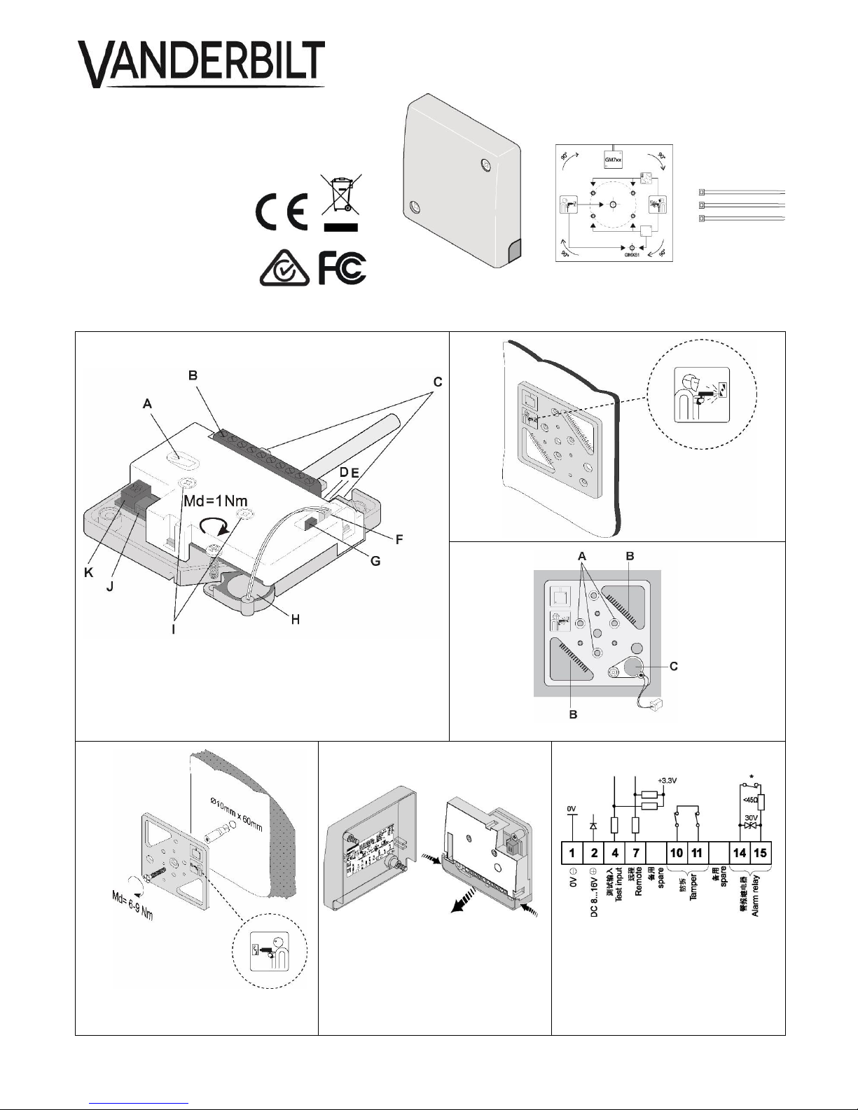
custom-set, thereby reducing the risk of false alarms. The anti-tamper for the detector
cover (Fig. 1, item A) will detect opening of the detector, and the anti-tamper on the back
of the detector will detect forcible removal.
Installation, programming and commissioning must be performed by
specialists.
Additional approval requirements can be found in the Appendix at the end
of this document.
3. Contents
1 x GM730 seismic detector
1 x GM7xx drilling template
3 x cable ties
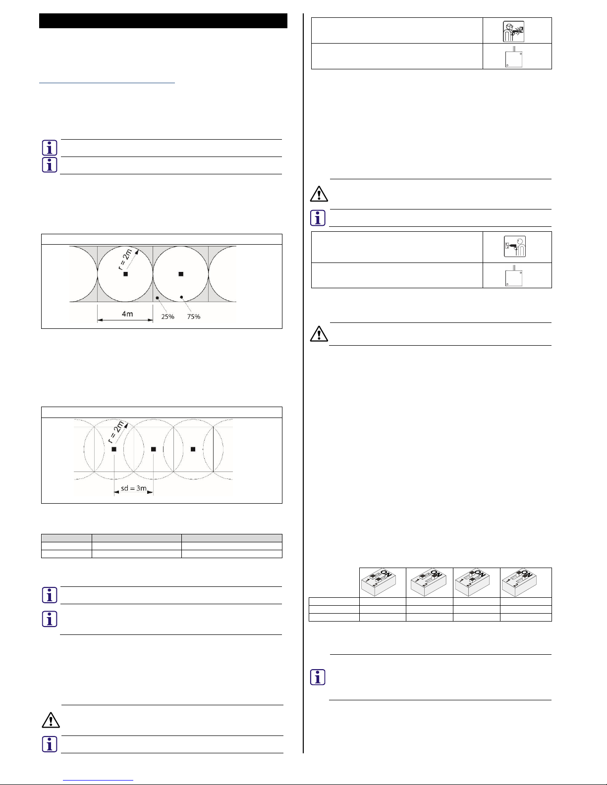
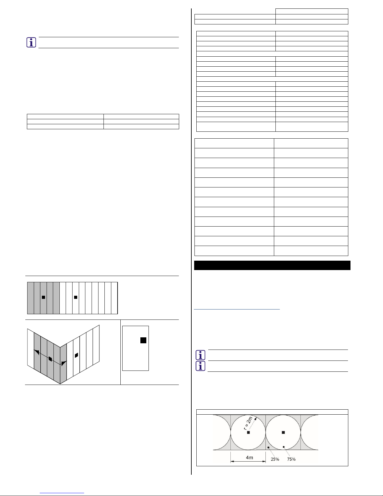
4. Coverage area
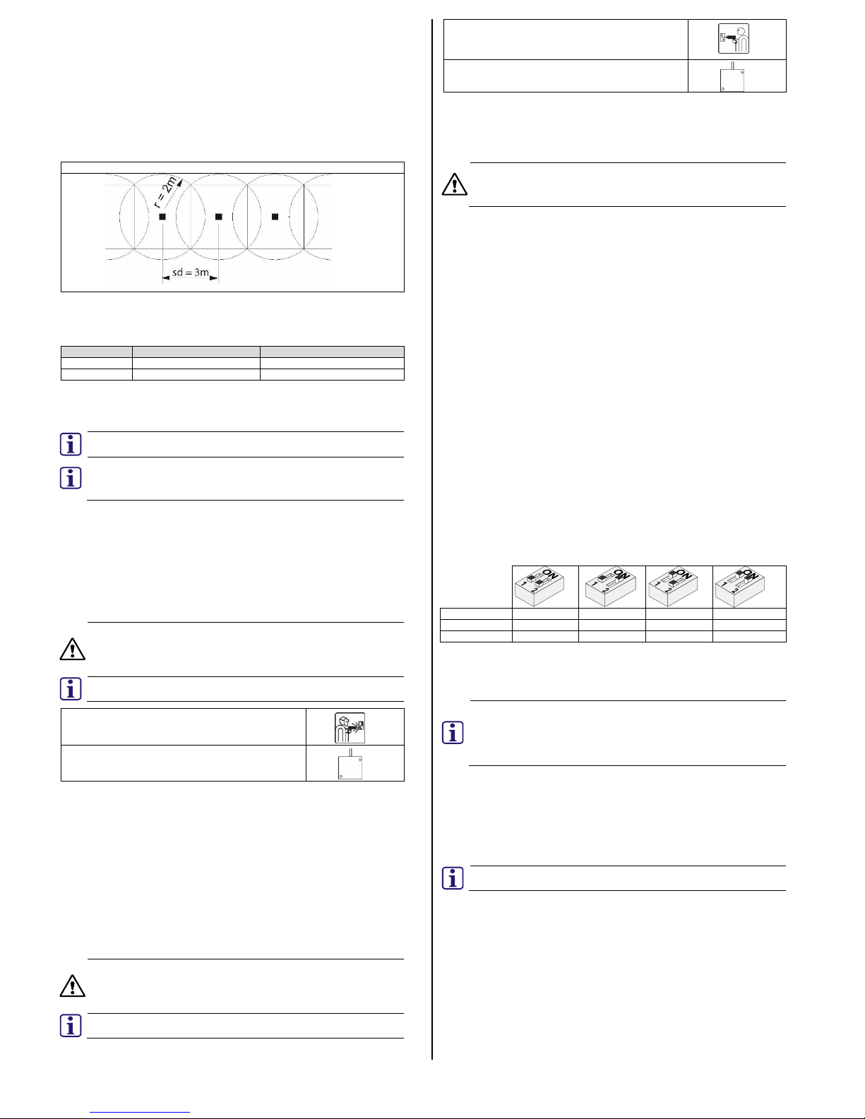
The area monitored by the detector is referred to as the coverage area. It covers the area
around the detector with an operating radius (r).
Detector coverage
Joints in the construction of the vault may impair the transmission of the signal. Doors
must have their own detector installed to provide the correct coverage.
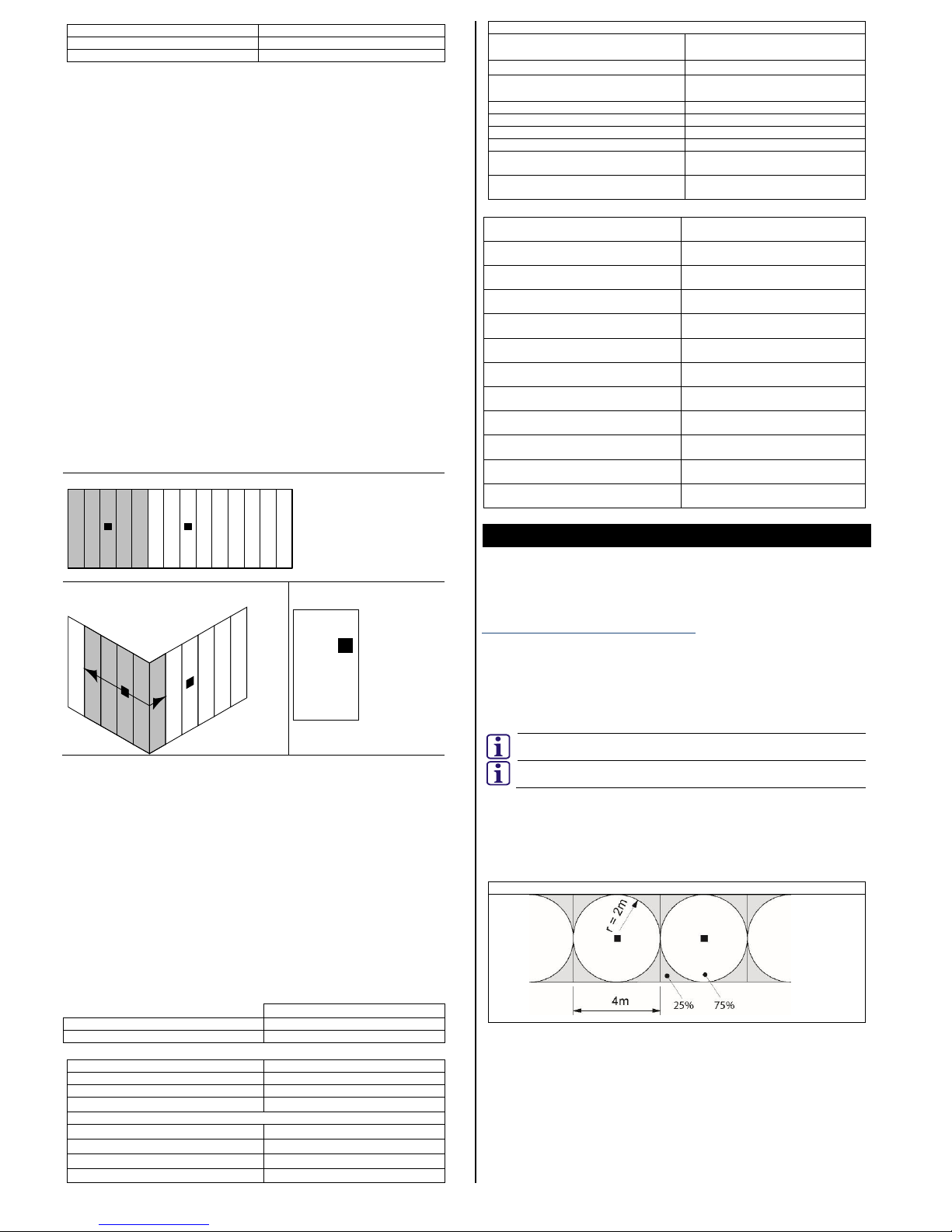
Tightly sealed corners and edges may reduce the operating radius (r) by >25%, therefore,
corners and edges on steel vaults must be seamlessly welded. Incorrect positioning can
reduce the coverage area. It is recommended that detectors are installed on each plane
(walls, floor, and ceiling) of the protected area. Coverage from adjoining planes should not
form part of a comprehensive protection strategy.
4.1. Detector spacing distance
Detectors should be positioned so that they cover the entire area to be monitored. The
distance between detectors is referrred to as the spacing distance (sd).
Detector spacing distance (sd)
To ensure complete coverage of the protected area, the following formula should be
applied to determine the correct spacing distance between seismic detectors.
Spacing distance (sd) = operating radius(r) x 2 x 0.75
Example:
Material
Operating radius (r)
Spacing distance (sd)
Steel
2m
3m
Concrete
4m
6m
5. Installation
5.1. Direct installation on steel
The GM730 seismic detector can be installed directly onto a flat, even metal surface.
Take note of the orientation of the GM730 seismic detector and the
required drill pattern.
There must be a direct connection between the detector and the mounting
surface. Paint, varnish, dirt, silicone or similar materials will impede the
acoustics. Remove these materials from the mounting location before
installation.
Use the GM7xx drilling template (provided) to determine the location of the required holes.
1. Drill 3 x 3.2mm holes, 6mm deep. 2 holes for the detector and 1 hole for the GMXS1
internal test transmitter (Fig. 1, item H).
2. Remove the drilling template.
3. Thread all holes to M4.
4. Secure the detector and the test transmitter to the mounting surface.
5.2. Installation on steel using the GMXP0 mounting plate
Use the weld symbol side of the GMXP0 mounting plate (Fig. 2) to install the detector on
uneven or reinforced steel surfaces.
The GMXP0 mounting plate can be used for installing a seismic detector on
a steel surface. It is essential to use the correct side and mounting
methods. The GMXP0 displays a detector symbol to indicate the direction
of the cable access to the detector.
Take note of the orientation of the GM730 seismic detector and the required
orientation of the GMXP0 mounting plate.
GMXP0 weld symbol
Detector symbol showing cable access at top
1. With the weld symbol visible, attach the GMXP0 to the mounting surface using two
fillet welds as shown (Fig. 3, item B).
If welding is not possible, use the GMXP0 as a drill template.
Mark the 3 centrally located countersunk holes (Fig. 3, item A).
Drill 3 x 3.2mm Ø holes (depth to be determined by the thickness of the
mounting surface).
Thread to M4.
Secure the GMXP0 using 3 x M4 countersunk screws (provided with GMXP0).
2. Mount the detector on to the GMXP0.
3. Mount the GMXS1 internal test transmitter on the designated location on the
GMXP0 (Fig. 3, item C) and connect to the detector (Fig. 1, item F).
5.3. Installation on concrete using the GMXP0 mounting plate (Fig. 4)
Use the drill symbol side of the GMXP0 mounting plate (Fig. 4) to install the detector on
concrete surfaces.
The GMXP0 mounting plate can be used for installing a seismic detector on
a concrete surface. It is essential to use the correct side and mounting
methods. The GMXP0 displays a detector symbol to indicate the direction
of the cable access to the detector.
Take note of the orientation of the GM730 seismic detector and the required
orientation of the GMXP0 mounting plate.
GMXP0 drill symbol
Detector symbol showing cable access at top
1. Use the GM7xx drilling template (provided) to determine the location of the required
holes.
2. Drill a 10mm Ø x 60mm hole and insert the steel expansion plug.
3. Drill a 5mm Ø x >22mm hole and insert the GMXS1 brass expansion plug.
When installing on concrete, the GMXS1 must not have any contact with
the GMXP0 mounting plate. The GMXS1 must be attached to the concrete
using the M4 x 21mm screw and the associated brass expansion plug.
4. Secure the GMXP0 to the steel expansion plug with the M6 x 47mm screw.
5. Secure the GMXS1 to the brass expansion plug with the M4 x 21mm screw.
6. Mount the detector on to the GMXP0.
6. Mounting the detector
1. Remove the cover from the detector.
2. Attach the detector to the prepared mounting base using the two mounting screws
(Fig. 1, item I).
3. Remove the cable access skirt (Fig. 5).
4. Wire the connection cables to the terminal (Fig. 1, item B) as shown in diagram (Fig.
6).
5. Secure the cable to a cable anchor (Fig. 1, items C) with a cable tie (provided).
6. Connect the accessories and program the detector.
7. Remove the pre-formed cable access points as required to enable cable access
through the skirt (Fig. 5).
8. Replace the cable access skirt.
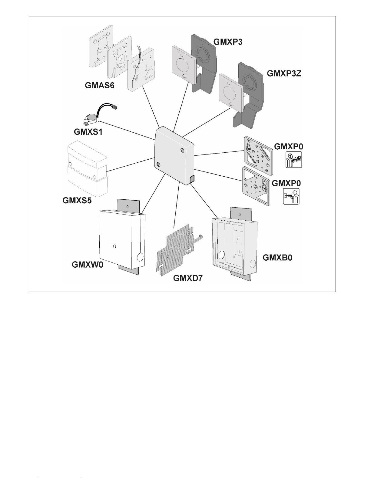
7. Accessories
All of the accessories (Fig. 7) have their own installation instructions, which are supplied
with each accessory. These installation instructions should be followed for the correct
installation and optimum performance from this seismic detector. For ordering information,
see section 14.
8. Programming
8.1. Application setting (Fig. 1, item G)
The specified operating radius applies to an attack with an oxygen lance. If attacked with
a mechanical tool (e.g. a drill) the value may be as much as three times higher. The
specified operating radius is a guideline which is heavily influenced by the characteristics
of the material and the type of construction.
Select the material type for the protected space and the required detection radius by
selecting the DIP switch options as follows:
Operating
radius (r)
Mode
Fixed
Fixed
Fixed
USER MODE
Steel
2m
1.5m
---
1* / 1,5 / 2m
Concrete
---
---
4m
2.5 / 4m
There are 3 settings selectable via the DIP switch (Fig. 2, item G). To enable the USER
MODE selectable settings through the GMSW7 SensTool software, DIP switches 1 & 2
must be in the ON position to establish communications between the PC and the detector.
8.2. Sensitivity (Fig. 6, terminal 7)
When this input is active, the sensitivity of the detector is reduced. The
sensitivity input should only be applied under special circumstances, and
only for short periods of time. Any reduction in sensitivity must comply with
applicable regulations such as VdS in Germany. The factory setting is
Active low. Active high is selectable through the GMSW7 SensTool
software.
Sensitivity is reduced to 12.5% of the original setting for the duration of the remote signal.
A potential application is the prevention of alarm triggering where loud functional noises
prevail.
Page 4
008321_o 4
8.3. Test input (Fig. 6, terminal 4)
The GMXS1 internal test transmitter (Fig. 1, item H) is activated by the application of a
low signal into the test input terminal. If the detector is functioning correctly, the detector
will trigger an alarm (trigger time <3s).
The factory setting is Active low. Active high is selectable through the GMSW7 SensTool
software.
Active low = 0 V applied to activate.
Active high = 0 V removed to activate.
9. LED display
The red LED (Fig. 1, item E) pulses during initialisation. In the event of an alarm, the LED
illuminates for approximately 2.5 seconds. This LED is only visible when the cover of the
detector is removed.
10. Commissioning
1. Apply the supply voltage.
The LED (Fig. 1, item E) pulses for 10 seconds.
2. Leave the detector for a further 20 seconds.
The detector is now operational.
3. Verify the correct radius and material type have been selected by the DIP switches
or SensTool.
If SensTool is not available, use a multimeter (Ri ≥ 20 kΩ) at terminal 1 (0 V) and at the
test point (Fig. 1, item D) to monitor for the analogue integration signal:
Quiescent level
0 V
Integration start
1 V
Alarm threshold (w/o load)
3 V
4. Check for interference using the SensTool > Analyse option. The Digital Filter
option in the Settings tab may assist in reducing inherent interference. For
additional information, please refer to the SensTool software and the associated
manual.
10.1. Functional Checks
Functional checks can be performed as follows:
With the cover removed, scratch the metal case of the detector with a screw driver
until the LED (Fig. 1, item E) confirms an alarm.
Apply the required input to terminal 4 to activate the GMXS1 internal test
transmitter, if provided.
Apply the required input to activate the GMXS5 external test transmitter, if provided.
Simulate an attack on the protected space.
Carefully replace the cover and secure it in place.
11. Service
The function of the detector and its mounting should be checked at least once a year, as
follows:
Functionally test the detector as detailed in section 10.1.
Verify the settings of the detector by the DIP switches or by the GMSW7 SensTool
software.
Check the mounting of the detector to ensure that the detector is securely attached.
Check that there is a direct connection between the detector and the mounting
surface. Paint, varnish, dirt, silicone or similar materials will impede the acoustics.
Refer to local approvals for guidance on this matter.
12. Modular vaults
The following principles must be strictly observed when using seismic detectors on
modular vaults made from steel or concrete.
Thickness from 100 to 400mm
Width up to 1000mm
Length up to 6500mm
Modules with detector arrangement
Corner joints between walls seamlessly welded
Always 1 detector on doors
Strict compliance with the following principles is vital when using seismic detectors on
modular vaults made from steel and concrete:
1. One detector for a maximum of 5 wall modules. The detector must be mounted on
the middle module.
2. In addition to being bolted together, all of the joints between the modules must be
welded every 400 − 500mm with a 30 − 40mm seam.
3. Corner joints between wall modules must be seamlessly welded if the coverage
area is to extend beyond the corners.
4. In the case of wall modules equipped with detectors, the immediately adjoining floor
and/or ceiling modules can be included in the coverage area if the corresponding
butt joints are seamlessly welded.
5. Where building vaults use modules of varying thickness, the butt joints must be
seamlessly welded.
6. Avoid mounting detectors on modules to which guide rails for cassette transport lifts,
ventilators or other mechanical equipment are attached.
7. Always equip modules which have a pay-in/withdrawal slot with a detector. The
detector can monitor the adjacent modules.
8. All doors must be equipped with a detector.
9. Programming:
Application setting
Maximum 5 modules
Concrete: 4m radius
Doors
Steel: 2m radius
13. Technical data
Dimensions
89mm x 89mm x 23mm
Supply voltage (nom. 12 V DC)
Vcc = 8 to 16 V DC
Current consumption (8 to 16 V DC)
Ityp = 2.5 to 3.5 mA
Alarm condition
Imax. = 5 mA
Alarm output, terminals 14+15:
Semiconductor relay
Opens on alarm + low voltage
Contact load
30 V DC/100 mA, ohmic load
Series resistance
<45 Ω
Alarm holding time
2.5 seconds
Sabotage surveillance terminals 10+11:
Microswitch, cover and floor
Opens on sabotage
Contact load
30 V DC/100 mA
Anti-drilling foil in cover
Sabotage Alarm
Test input, terminal 4
Low <1.5 V DC/High >3.5 V DC
Remote input, terminal 7
Low <1.5 V DC/High >3.5 V DC
Operating temperature
-40 ºC to +70 ºC
Storage temperature
-40 ºC to +70 ºC
Air humidity (EN 60721), non-condensing
<95%
Approvals
See the type plate inside the detector
cover (Fig. 5)
14. Ordering information
GM730
Seismic detector
V54534-F107-A100
GMXP0
Mounting plate – GM7xx
VBPZ:2772730001
GMXS1
Internal test transmitter – GM7xx
VBPZ:4202370001
GMXS5
External test transmitter – GM7xx
VBPZ:5627000001
GMXW0
Wall / Ceiling recess box – GM7xx
VBPZ:2771210001
GMXB0
Floor recess box – GM7xx
VBPZ:2772020001
GMXP3
Lock protection – GM7xx
VBPZ:3470190001
GMXP3Z
Lock protection – GM7xx
VBPZ:5712410001
GMAS6
Movable mounting kit – GM7xx
VBPZ:4886060001
GMXD7
Anti-drill foil(10x) – GM730/760/775
VA5Q00006245
GMSW7
SensTool-SW – GM730/760/775
VA5Q00006245
GMXC2
Connection sleeve (16mm) – GM7xx
VBPZ:5021840001
de
1. EG-Konformitätserklärung
Hiermit erklärt Vanderbilt International (IRL) Ltd, dass dieser Gerätetyp den
Anforderungen aller relevanten EU-Richtlinien für die CE-Kennzeichnung entspricht. Ab
dem 20.04.2016 entspricht er der Richtlinie 2014/30/EU (Richtlinie über
elektromagnetische Verträglichkeit).
Der vollständige Text der EU-Konformitätserklärung steht unter folgender Internetadresse
zur Verfügung:
http://pcd.vanderbiltindustries.com/doc/Seismic.
2. Anwendung
Der Körperschallmelder GM730 erkennt zuverlässig Aufbruchsversuche bei Safes,
Geldautomaten, Fahrscheinautomaten, Nachttresoren, Stahlkammern und Tresorräumen
aus Stahl oder Beton. Die intelligente Signalverarbeitung erlaubt eine individuelle
Einstellung der Detektionsempfindlichkeit und somit eine hohe Sicherheit gegen
Falschalarm. Der Sabotageschutz für die Melderabdeckung (Abb. 1, Element A) erkennt
ein Öffnen des Melders. Der Sabotageschutz auf der Rückseite des Melders erkennt ein
gewaltsames Entfernen.
Die Montage, Programmierung und Inbetriebnahme müssen durch
Fachpersonen erfolgen.
Zusätzliche Zulassungsanforderungen sind im Anhang am Ende dieses
Dokuments enthalten.
3. Inhalt
1 Körperschallmelder GM730
1 Bohrschablone GM7xx
3 Kabelbinder
4. Wirkbereich
Die vom Melder überwachte Fläche wird als Wirkbereich bezeichnet. Dieser breitet sich
kreisförmig vom Melder mit einem Wirkradius (r) aus.
Melderwirkung
1 2 3 4 5 1 2 3 4 5 . . . .
Page 5
008321_o 5
Verbindungsstellen in der Tresorkonstruktion können die Signalübertragung
beeinträchtigen. Türen müssen über einen eigenen Melder verfügen, um eine
ordnungsgemäße Melderwirkung zu erzielen.
Gut abgedichtete Ecken und Kanten können den Wirkradius (r) um > 25 % verringern,
weshalb Ecken und Kanten bei Stahltresoren durchgehend verschweißt sein müssen.
Eine falsche Positionierung kann den Wirkbereich reduzieren. Es wird empfohlen, auf
jeder Fläche (Wände, Boden und Decke) des zu schützenden Bereichs Melder zu
montieren. Eine Erfassung von angrenzenden Flächen aus sollte nicht Bestandtteil einer
umfassenden Schutzstrategie sein.
4.1. Melderabstand
Melder müssen so positioniert werden, dass sie den gesamten zu überwachenden
Bereich abdecken. Der Abstand zwischen den Meldern wird als Melderabstand
bezeichnet (sd – engl. spacing distance).
Melderabstand (sd)
Für eine vollständige Abdeckung des zu schützenden Bereichs sollte die folgende Formel
angewendet werden, um den korrekten Abstand zwischen den Körperschallmeldern zu
bestimmen.
Melderabstand (sd) = Wirkradius (r) × 2 × 0,75
Beispiel:
Material
Wirkradius (r)
Melderabstand (sd)
Stahl
2m
3m
Beton
4m
6m
5. Montage
5.1. Direkte Montage auf Stahl
Der Körperschallmelder GM730 kann direkt auf einer flachen, ebenen Metallfläche
montiert werden.
Achten Sie darauf, dass der Körperschallmelder GM730 und das passende
Bohrmuster aufeinander ausgerichtet sind.
Zwischen Melder und Montagefläche muss eine direkte Verbindung
bestehen. Farben, Lacke, Schmutz, Silikon o. Ä. behindern die
Schallübertragung. Entfernen Sie diese Materialien von der Montagefläche,
bevor Sie mit der Montage beginnen.
Verwenden Sie die beiliegende Bohrschablone GM7xx, um die Position der erforderlichen
Bohrungen zu bestimmen.
1. Bohren Sie drei Löcher mit einem Durchmesser von 3,2mm und einer Tiefe von
6mm. Zwei Löcher für den Melder und ein Loch für den internen Prüfsender GMXS1
(Abb. 1, Element H).
2. Entfernen Sie die Bohrschablone.
3. Schneiden Sie in alle Bohrungen ein M4-Gewinde.
4. Befestigen Sie den Melder und den Prüfsender auf der Montagefläche.
5.2. Montage auf Stahl mithilfe der Montageplatte GMXP0
Verwenden Sie die Seite der Montageplatte GMXP0 mit dem Schweißsymbol (Abb. 2),
um den Melder auf unebenen oder verstärkten Stahlflächen zu montieren.
Die Montageplatte GMXP0 kann für die Montage eines
Körperschallmelders auf einer Stahlfläche verwendet werden. Es ist
ausschlaggebend, dass die richtige Seite und die korrekten
Montagemethoden verwendet werden. Die GMXP0 trägt ein Meldersymbol,
das die Ausrichtung der Kabelzuführung zum Melder anzeigt.
Achten Sie darauf, dass der Körperschallmelder GM730 und die
Montageplatte GMXP0 aufeinander ausgerichtet sind.
GMXP0-Schweißsymbol
Meldersymbol mit Kabelzuführung auf Oberseite
1. Befestigen Sie die Montageplatte GMXP0 mit zwei Kehlnähten auf der
Montagefläche. Das Schweißsymbol muss sichtbar sein (siehe Abb. 3, Element B).
Wenn kein Schweißen möglich ist, verwenden Sie die GMXP0 als Bohrschablone.
Markieren Sie die drei mittig liegenden Senkbohrungen (Abb. 3, Element A).
Bohren Sie drei Löcher mit einem Durchmesser von 3,2mm (die Tiefe der
Bohrung muss abhängig von der Stärke der Montagefläche bestimmt werden).
Schneiden Sie anschließend M4-Gewinde in alle Bohrungen.
Befestigen Sie die GMXP0 mithilfe von Senkkopfschrauben (3 × M4, im
Lieferumfang der GMXP0 enthalten).
2. Montieren Sie den Melder auf der GMXP0.
3. Montieren Sie den internen Prüfsender GMXS1 an der angegebenen Position auf
der GMXP0 (Abb. 3, Element C), und schließen Sie ihn an den Melder an (Abb. 1,
Element F).
5.3. Montage auf Beton mithilfe der Montageplatte GMXP0 (Abb. 4)
Verwenden Sie die Seite der Montageplatte GMXP0 mit dem Bohrsymbol (Abb. 4), um
den Melder auf Betonflächen zu montieren.
Die Montageplatte GMXP0 kann für die Montage eines
Körperschallmelders auf einer Betonfläche verwendet werden. Es ist
ausschlaggebend, dass die richtige Seite und die korrekten
Montagemethoden verwendet werden. Die GMXP0 trägt ein Meldersymbol,
das die Ausrichtung der Kabelzuführung zum Melder anzeigt.
Achten Sie darauf, dass der Körperschallmelder GM730 und die
Montageplatte GMXP0 aufeinander ausgerichtet sind.
GMXP0-Bohrsymbol
Meldersymbol mit Kabelzuführung auf Oberseite
1. Verwenden Sie die beiliegende Bohrschablone GM7xx, um die Position der
erforderlichen Bohrungen zu bestimmen.
2. Bohren Sie ein Loch mit einem Durchmesser von 10mm und einer Tiefe von 60mm,
und setzen Sie den Stahlspreizdübel ein.
3. Bohren Sie ein Loch mit einem Durchmesser von 5mm und einer Tiefe von > 22mm,
und setzen Sie den GMXS1-Messingspreizdübel ein.
Bei der Montage auf Beton darf der GMXS1 keinen Kontakt mit der
Montageplatte GMXP0 haben. Der GMXS1 muss mithilfe der Schraube
(M4 × 21mm) und dem dazugehörigen Messingspreizdübel am Beton
befestigt werden.
4. Befestigen Sie die GMXP0 mithilfe der Schraube (M6 × 47mm) am
Stahlspreizdübel.
5. Befestigen Sie den GMXS1 mit der Schraube (M4 × 21mm) am
Messingspreizdübel.
6. Montieren Sie den Melder auf der GMXP0.
6. Montage des Melders
1. Entfernen Sie die Abdeckung vom Melder.
2. Bringen Sie den Melder auf der vorbereiteten Befestigungsplatte mithilfe der zwei
Befestigungsschrauben an (Abb. 1, Element I).
3. Entfernen Sie die Verkleidung der Kabelzuführung (Abb. 5).
4. Führen Sie die Verbindungskabel zur Zentrale (Abb. 1, Element B) wie in der
Abbildung dargestellt (Abb. 6).
5. Befestigen Sie das Kabel mit einem (beiliegenden) Kabelbinder an einer
Kabelklemme (Abb. 1, Element C).
6. Schließen Sie das Zubehör an und programmieren Sie den Melder.
7. Entfernen Sie die vorgestanzten Abdeckungen an den
Kabelzuführungsaussparungen wie erforderlich, um die Kabelzuführung durch die
Verkleidung zu ermöglichen (Abb. 5).
8. Bringen Sie die Verkleidung der Kabelzuführung wieder an.
7. Zubehör
Für alle Zubehörteile (Abb. 7) gelten eigene Montageanweisungen, die jedem Zubehörteil
beiliegen. Diese Montageanweisungen müssen für die korrekte Montage und eine
optimale Leistung dieses Körperschallmelders befolgt werden. Bestellangaben siehe
Abschnitt 14.
8. Programmierung
8.1. Anwendungseinstellung (Abb. 1, Element G)
Der angegebene Wirkradius gilt für einen Angriff mit Sauerstofflanze. Bei einem Angriff
mit mechanischem Werkzeug (z. B. Bohrer) kann sich der Wert bis auf das Dreifache
erhöhen. Der angegebene Wirkradius ist ein Richtwert, der stark von der Beschaffenheit
des Untergrunds beeinflusst wird.
Wählen Sie den Materialtyp für den zu schützenden Bereich und den erforderlichen
Wirkradius, indem Sie die DIP-Schaltoptionen wie folgt festlegen:
Wirkradius (r)
Modus
Fest
Fest
Fest
USER MODE
Stahl
2m
1,5m
---
1* / 1,5 / 2m
Beton
---
---
4m
2,5 / 4m
Über den DIP-Schalter können 3 Einstellungen gewählt werden (Abb. 2, Element G). Zur
Aktivierung der auswählbaren USER MODE-Einstellungen über die GMSW7 SensToolSoftware müssen die DIP-Schalter 1 und 2 in der EIN-Position sein, um die
Kommunikation zwischen dem PC und dem Melder herzustellen.
8.2. Empfindlichkeit (Abb. 6, Klemme 7)
Wenn dieser Eingang aktiv ist, wird die Melderempfindlichkeit verringert.
Der Empfindlichkeitseingang darf nur unter bestimmtem Umständen
angewendet werden, und das nur für kurze Zeiträume. Die Reduzierung der
Empfindlichkeit muss in Übereinstimmung mit den geltenden Vorschriften
(z. B. gemäß VdS) erfolgen. Die Werkseinstellung ist Low-aktiv. High-aktiv
kann mithilfe der GMSW7 SensTool-Software gewählt werden.
Die Empfindlichkeit wird für die Dauer des Fernsignals auf 12,5 % der Originaleinstellung
reduziert. Eine potentielle Anwendung ist die Verhinderung der Alarmauslösung bei
starken funktionsbedingten Geräuschen.
8.3. Testeingang (Abb. 6, Klemme 4)
Der interne Prüfsender GMXS1 (Abb. 1, Element H) wird durch das Anlegen eines
niedrigen Signals an die Testeingangsklemme aktiviert. Bei korrekt funktionierendem
Melder löst dieser einen Alarm aus (Auslösezeit < 3 s).
Die Werkseinstellung ist Low-aktiv. High-aktiv kann mithilfe der GMSW7 SensToolSoftware gewählt werden.
Low-aktiv = Anlegen von 0 V zur Aktivierung
High-aktiv = Entfernen von 0 V zur Aktivierung
9. LED-Anzeige
Die rote LED (Abb. 1, Element E) blinkt während der Initialisierung. Bei einem Alarm
leuchtet die LED ca. 2,5 s lang. Diese LED ist nur sichtbar, wenn die Abdeckung des
Melders entfernt wurde.
10. Inbetriebnahme
1. Legen Sie die Versorgungsspannung an.
Die LED (Abb. 1, Element E) blinkt 10 Sekunden lang.
2. Lassen Sie den Melder weitere 20 Sekunden lang in Ruhe.
Der Melder ist nun betriebsbereit.
3. Überprüfen Sie, ob der korrekte Radius und Materialtyp mithilfe der DIP-Schalter
oder SensTool gewählt wurden.
Wenn SensTool nicht verfügbar ist, verwenden Sie ein Multimeter (Ri ≥ 20 kΩ) an
Klemme 1 (0 V) und Testpunkt (Abb. 1, Element D), um auf ein analoges
Integrationssignal zu prüfen:
Page 6
008321_o 6
Ruhepegel
0 V
Integrationsstart
1 V
Alarmschwelle (unbelastet)
3 V
4. Prüfen Sie auf Interferenz mithilfe der Option „SensTool > Analysieren“. Die Option
Digitalfilter auf der Registerkarte Einstellungen könnte bei der Verringerung der
inhärenten Störung helfen. Zusätzliche Informationen finden Sie in der SensToolSoftware und dem dazugehörigen Handbuch.
10.1. Funktionsprüfungen
Funktionsprüfungen können wie folgt ausgeführt werden:
Nehmen Sie die Abdeckung ab und kratzen Sie das Metallgehäuse des Melders mit
einem Schraubendreher an, bis die LED (Abb. 1, Element E) einen Alarm anzeigt.
Legen Sie das erforderliche Eingangssignal an Klemme 4 an, um den internen
Prüfsender GMXS1 (falls vorhanden) zu aktivieren.
Legen Sie das erforderliche Eingangssignal an, um den externen
Prüfsender GMXS5 (falls vorhanden) zu aktivieren.
Simulieren Sie einen Angriff auf den zu schützenden Bereich.
Setzen Sie die Abdeckung wieder auf und sichern Sie sie.
11. Service
Die Funktion des Melders und dessen Montage müssen mindestens einmal jährlich wie
folgt geprüft werden:
Testen Sie den Melder auf eine ordnungsgemäße Funktion entsprechend
Abschnitt 10.1.
Überprüfen Sie die Einstellungen des Melders mithilfe der DIP-Schalter oder der
GMSW7 SensTool-Software.
Überprüfen Sie die Montage des Melders, um sicherzustellen, dass er sicher
befestigt ist.
Überprüfen Sie, ob ein direkter Kontakt zwischen dem Melder und der
Montagefläche besteht. Farben, Lacke, Schmutz, Silikon o. Ä. behindern die
Schallübertragung.
Siehe lokale Zulassungen für weitere Informationen zu diesem Thema.
12. Elementtresore
Beim Einsatz des Körperschallmelders in und an Elementtresoren aus Stahl und
Betonmaterial sind folgende Grundsätze unbedingt zu beachten.
Stärke von 100 bis 400mm
Breite bis 1.000mm
Länge bis 6.500mm
Elemente mit Melderanordnung
Eckverbindung Wand/Wand durchgehend
verschweißt
Immer 1 Melder an Türen
Beim Einsatz des Körperschallmelders auf Elementtresoren aus Stahl und Betonmaterial
sind folgende Grundsätze unbedingt zu beachten:
1. Ein Melder für jeweils maximal 5 Wandelemente. Der Melder muss auf dem
mittleren Element montiert werden.
2. Alle Fugen zwischen den Elementen müssen zusätzlich zu einer Verschraubung
punktuell alle 400 bis 500mm mit einer 30 bis 40mm langen Schweißnaht
verschweißt sein.
3. Eckverbindungen bei Wandelementen müssen durchgehend verschweißt werden,
wenn der Wirkbereich sich auch über die Ecken erstrecken soll.
4. Werden Wandelemente mit Meldern bestückt, kann das direkt angrenzende Bodenund/oder Deckenelement in den Wirkbereich mit einbezogen werden, wenn die
entsprechende Stoßstelle durchgehend verschweißt wird.
5. Wenn in Tresoren unterschiedliche Elementdicken kombiniert werden, müssen die
Stoßstellen durchgehend verschweißt werden.
6. Bringen Sie Melder soweit möglich nicht auf Elementen an, an denen
Führungsschienen von Kassetten-Transportlifts, Ventilatoren oder andere
mechanische Einrichtungen befestigt sind.
7. Verwenden Sie immer Elemente, die mit einer Ein-/Ausgabeöffnung mit Melder
ausgestattet sind. Der Melder kann die angrenzenden Elemente überwachen.
8. Jede Tür muss mit einem eigenen Melder ausgestattet sein.
9. Programmierung:
Anwendungseinstellung
Maximal 5 Module
Beton: 4 m Radius
Türen
Stahl: 2 m Radius
13. Technische Daten
Abmessungen
89mm × 89mm × 23mm
Versorgungsspannung (nom. 12 V DC)
Vcc = 8 bis 16 V DC
Stromaufnahme (8 bis 16 V DC)
Ityp = 2,5 bis 3,5 mA
Alarmbedingung
Imax. = 5 mA
Alarmausgang, Klemmen 14+15:
Halbleiterrelais
Öffnet bei Alarm + Unterspannung
Kontaktlast
30 V DC/100 mA, ohmsche Last
Reihenwiderstand
< 45 Ω
Alarmhaltezeit
2,5 Sekunden
Sabotageüberwachungsklemmen 10+11:
Mikroschalter, Abdeckung und
Boden
Öffnet bei Sabotage
Kontaktlast
30 V DC/100 mA
Bohrschutzfolie in der
Abdeckung
Sabotage Alarm
Testeingang, Klemme 4
Low < 1,5 V DC / High > 3,5 V DC
Fernzugriffseingang, Klemme 7
Low < 1,5 V DC / High > 3,5 V DC
Betriebstemperatur
–40 bis 70 °C
Lagertemperatur
–40 bis 70 °C
Luftfeuchtigkeit (EN 60721), nicht
kondensierend
< 95 %
Zulassungen
Siehe Typenschild auf Innenseite der
Abdeckung (Abb. 5)
14. Bestellangaben
GM730
Körperschallmelder
V54534-F107-A100
GMXP0
Montageplatte – GM7xx
VBPZ:2772730001
GMXS1
Interner Prüfsender – GM7xx
VBPZ:4202370001
GMXS5
Externer Prüfsender – GM7xx
VBPZ:5627000001
GMXW0
Wand-/Deckeneinbaudose – GM7xx
VBPZ:2771210001
GMXB0
Bodeneinbaudose – GM7xx
VBPZ:2772020001
GMXP3
Schlossschutz – GM7xx
VBPZ:3470190001
GMXP3Z
Schlossschutz – GM7xx
VBPZ:5712410001
GMAS6
Bewegliches Montagekit – GM7xx
VBPZ:4886060001
GMXD7
Bohrschutzfolie (10×) – GM730/760/775
VA5Q00006245
GMSW7
SensTool-SW – GM730/760/775
VA5Q00006245
GMXC2
Anschlussmuffe (16mm) – GM7xx
VBPZ:5021840001
es
1. Declaración de conformidad CE
Por la presente, Vanderbilt International (IRL) Ltd declara que este tipo de equipo cumple
con todas las directivas de la UE relevantes para el marcado CE. Desde el 20/04/2016
cumple con la directiva 2014/30/UE (directiva de compatibilidad electromagnética).
El texto completo de la declaración UE de conformidad está disponible en la siguiente
dirección de Internet:
http://pcd.vanderbiltindustries.com/doc/Seismic.
2. Aplicación
El detector sísmico GM730 detecta fiablemente intentos de apertura forzada en cajas
fuertes, cajeros automáticos, dispensadores automáticos de billetes, depósitos nocturnos,
cámaras de seguridad y cámaras acorazadas de acero u hormigón. El inteligente
procesamiento de las señales permite un ajuste individual de la sensibilidad de detección
y, por lo tanto, una alta seguridad contra falsas alarmas. El sistema antimanipulación para
la cubierta del detector (Fig. 1, elemento A) detecta la apertura del detector, y el sistema
antimanipulación de la parte trasera del detector detecta el desmontaje forzado.
El montaje, la programación y la puesta en servicio deben ser realizados
por especialistas.
Para los requisitos adicionales de la homologación, consulte el anexo al
final de este documento.
3. Contenido
1 x detector sísmico GM730
1 x plantilla de taladrado GM7xx
3 x bridas para cables
4. Área efectiva
El área monitorizada por el detector se denomina área efectiva. El detector ofrece una
cobertura circular del área con un radio de acción (r).
Cobertura del detector
Las juntas en la construcción de la caja fuerte pueden afectar a la transmisión de la
señal. Las puertas deben tener su propio detector instalado para proporcionar la
cobertura correcta.
Las esquinas y los bordes bien sellados pueden reducir el radio de acción (r) en un 25 %;
por este motivo, las esquinas y los bordes de las cajas fuertes de acero deben estar
soldados de forma continua. Un posicionamiento erróneo puede reducir el área efectiva.
Se recomienda instalar detectores en todos los planos (paredes, suelo y techo) del área
protegida. La cobertura desde planos adyacentes no debe formar parte de una estrategia
amplia de protección.
4.1. Distancia de separación entre detectores
Los detectores deben posicionarse de manera que cubran todo el área a monitorizar. La
distancia entre detectores se denomina distancia de separación (sd).
1 2 3 4 5 1 2 3 4 5 . . . .
Page 7

008321_o 7
Distancia de espaciado entre detectores (sd)
A fin de garantizar la cobertura completa del área protegida, se debe aplicar la siguiente
fórmula para determinar la distancia de separación entre detectores sísmicos.
Distancia de separación (sd) = radio de acción (r) x 2 x 0,75
Ejemplo:
Material
Radio de acción (r)
Distancia de separación (sd)
Acero
2m
3m
Hormigón
4m
6m
5. Instalación
5.1. Montaje directo sobre acero
El detector sísmico GM730 se puede instalar directamente sobre una superficie metálica
plana y uniforme.
Tome nota de la orientación del detector sísmico GM730 y del patrón de
taladrado necesario.
Entre el detector y la superficie de montaje debe haber una conexión
directa. Las pinturas, los barnices, la suciedad, la silicona y otros
materiales similares pueden obstaculizar la transmisión acústica. Retire
estos materiales del lugar de montaje antes de realizar la instalación.
Utilice la plantilla de taladrado GM7xx (incluida) para determinar el emplazamiento de los
orificios necesarios.
1. Taladre 3 orificios de 3,2mm de diámetro y 6mm de profundidad. Dos orificios son
para el detector y uno para el emisor de prueba interno GMXS1 (Fig. 1, elemento
H).
2. Retire la plantilla de taladrado.
3. Realice en todos los orificios una rosca M4.
4. Fije el detector y el emisor de prueba a la superficie de montaje.
5.2. Instalación sobre acero utilizando la placa de montaje GMXP0
Utilice el lado del símbolo de soldadura de la placa de montaje GMXP0 (Fig. 2) para
instalar el detector sobre superficies de acero irregulares o templadas.
La placa de montaje GMXP0 sirve para instalar un detector sísmico sobre
una superficie de acero. Es fundamental utilizar el lado y los métodos de
montaje correctos. En la placa GMXP0 se puede ver un símbolo de
detector que indica la dirección del acceso de los cables al detector.
Tome nota de la orientación del detector sísmico GM730 y de la orientación
necesaria de la placa de montaje GMXP0.
Símbolo de soldadura en GMXP0
Símbolo del detector que muestra el acceso de los cables
por la parte superior
1. Con el símbolo de soldadura visible, fije la placa GMXP0 a la superficie de montaje
con dos soldaduras en ángulo, tal como se muestra en la ilustración (Fig. 3,
elemento B).
Si no es posible soldar, utilice la placa GMXP0 como plantilla de taladrado.
Marque los 3 orificios avellanados situados en el centro (Fig. 3, elemento A).
Taladre 3 orificios de 3,2mm de diámetro (la profundidad estará determinada
por el grosor de la superficie de montaje).
Realice una rosca M4.
Fije la placa GMXP0 con 3 tornillos avellanados M4 (incluidos con la placa
GMXP0).
2. Monte el detector sobre la placa GMXP0.
3. Monte el emisor de prueba interno GMXS1 en el emplazamiento designado sobre la
placa GMXP0 (Fig. 3, elemento C) y conéctelo al detector (Fig. 1, elemento F).
5.3. Instalación sobre hormigón utilizando la placa de montaje GMXP0 (Fig. 4)
Utilice el lado indicado por el símbolo de taladrado de la placa de montaje GMXP0 (Fig.
4) para instalar el detector sobre superficies de hormigón.
La placa de montaje GMXP0 sirve para instalar un detector sísmico sobre
una superficie de hormigón. Es fundamental utilizar el lado y los métodos
de montaje correctos. En la placa GMXP0 se puede ver un símbolo de
detector que indica la dirección del acceso de los cables al detector.
Tome nota de la orientación del detector sísmico GM730 y de la
orientación necesaria de la placa de montaje GMXP0.
Símbolo de taladrado en GMXP0
Símbolo del detector que muestra el acceso de los cables
por la parte superior
1. Utilice la plantilla de taladrado GM7xx (incluida) para determinar el emplazamiento
de los orificios necesarios.
2. Taladre un orificio de Ø10mm × 60mm e inserte el taco de expansión de acero.
3. Taladre un orificio de Ø5mm × >22mm e inserte el taco de expansión de bronce
GMXS1.
Cuando se instala sobre hormigón, el GMXS1 no debe tener contacto
alguno con la placa de montaje GMXP0. El GMXS1 se debe unir al
hormigón con el tornillo M4 × 21mm y el taco de expansión de bronce
correspondiente.
4. Fije la placa GMXP0 al taco de expansión de acero con el tornillo M6 × 47mm.
5. Fije el GMXS1 al taco de expansión de bronce con el tornillo M4 × 21mm.
6. Monte el detector sobre la placa GMXP0.
6. Montaje del detector
1. Retire la cubierta del detector.
2. Fije el detector a la base de montaje ya preparada con los dos tornillos de montaje
(Fig. 1, elemento I).
3. Retire el zócalo de acceso de cables (Fig. 5).
4. Conecte los cables de conexión al terminal (Fig. 1, elemento B) tal como se
muestra en el diagrama (Fig. 6).
5. Asegure el cable a un anclaje de cable (Fig. 1, elementos C) con una brida para
cables (incluida en el suministro).
6. Conecte los accesorios y programe el detector.
7. Retire las entradas de cables pretroqueladas según sea necesario para poder
introducir los cables a través del zócalo (Fig. 5).
8. Vuelva a colocar el zócalo de acceso de cables.
7. Accesorios
Todos los accesorios (Fig. 7) se suministran con sus propias instrucciones de instalación.
Es necesario seguir estas instrucciones de instalación para conseguir una instalación
correcta y un rendimiento óptimo del detector sísmico. Para información sobre pedidos,
consulte el apartado 14.
8. Programación
8.1. Configuración de la aplicación (Fig. 1, elemento G)
El radio de acción especificado es válido para un ataque con una lanza de oxígeno. En
caso de ataque con una herramienta mecánica (p. ej. un taladro), el valor puede hasta
triplicarse. El radio de acción especificado es un valor orientativo en el que influyen
mucho las características del material y el tipo de construcción.
Elija el tipo de material para el espacio protegido y el radio de detección requerido
seleccionando las opciones del interruptor DIP tal como se indica a continuación:
Radio de acción
(r)
Modo
Fijo
Fijo
Fijo
MODO
USUARIO
Acero
2m
1,5m
---
1* / 1,5 / 2m
Hormigón
---
---
4m
2,5 / 4m
Hay tres ajustes seleccionables a través del interruptor DIP (Fig. 2, elemento G). Para
habilitar los ajustes seleccionables en el MODO USUARIO mediante el software
SensTool del GMSW7, los interruptores DIP 1 y 2 deben estar en la posición ON para
que se puedan establecer comunicaciones entre el PC y el detector.
8.2. Sensibilidad (Fig. 6, terminal 7)
Cuando esta entrada está activa, la sensibilidad del detector se reduce. La
entrada de sensibilidad únicamente se debe aplicar en circunstancias
especiales, y solo brevemente. La reducción de la sensibilidad debe
realizarse de acuerdo con la normativa vigente, como la VdS en Alemania.
El ajuste de fábrica es Activo "Bajo". Activo "Alto" se puede seleccionar con
el software SensTool del GMSW7.
Durante la duración de la señal remota, la sensibilidad se reduce a un 12,5 % del ajuste
original. Una posible aplicación es evitar que se dispare la alarma en los casos en los que
prevalecen los ruidos relacionados con el funcionamiento.
8.3. Entrada de prueba (Fig. 6, terminal 4)
El emisor de prueba interno GMXS1 (Fig. 1, elemento H) se activa aplicando una señal
baja al terminal de entrada de prueba. Si el detector funciona correctamente, disparará
una alarma (tiempo de activación <3 s).
El ajuste de fábrica es Activo "Bajo". Activo "Alto" se puede seleccionar con el software
SensTool del GMSW7.
Activo "Bajo" = 0 V aplicados para activar
Activo "Alto" = 0 V eliminados para activar
9. Indicador LED
El LED rojo (Fig. 1, elemento E) parpadea durante la inicialización. En caso de alarma, el
LED se enciende durante aprox. 2,5 segundos. El LED solo está visible cuando la
cubierta del detector está quitada.
10. Puesta en servicio
1. Encienda la tensión de alimentación.
El LED (Fig. 1, elemento E) parpadea durante 10 segundos.
2. Espere otros 20 segundos.
A continuación, el detector ya está operativo.
3. Compruebe que se han seleccionado el radio y el tipo de material correctos con los
interruptores DIP o con SensTool.
Si SensTool no está disponible, utilice un multímetro (Ri ≥ 20 kΩ) en el terminal 1 (0 V) y
en el punto de comprobación (Fig. 1, elemento D) para monitorizar la señal de integración
analógica:
Nivel en reposo
0 V
Inicio de la integración
1 V
Umbral de alarma (sin carga)
3 V
4. Compruebe las posibles interferencias con la opción SensTool > Análisis. La
opción Filtro digital en la ficha Configuración puede ayudar a reducir las
interferencias inherentes. Para más información, consulte el software SensTool y el
manual asociado.
10.1. Comprobaciones funcionales
Se pueden realizar las siguientes comprobaciones funcionales:
Con la cubierta quitada, arañe la carcasa metálica del detector con un destornillador
hasta que el LED (Fig. 1, elemento E) confirme una alarma.
Aplique la entrada requerida al terminal 4 para activar el emisor de prueba interno
GMXS1, si está incluido.
Aplique la entrada requerida para activar el emisor de prueba externo GMXS5, si
está incluido.
Simule un ataque del área protegida.
Vuelva a colocar la cubierta en su sitio con cuidado y atorníllela.
11. Servicio técnico
Compruebe el funcionamiento y la fijación al menos una vez al año, como se indica a
continuación:
Page 8

008321_o 8
Compruebe el funcionamiento del detector tal como se indica detalladamente en el
apartado 10.1.
Verifique la configuración del detector con los interruptores DIP o con el software
SensTool del GMSW7.
Compruebe el montaje del detector para asegurarse de que está fijado de forma
segura.
Compruebe que haya una conexión directa entre el detector y la superficie de
montaje. Las pinturas, los barnices, la suciedad, la silicona y otros materiales
similares pueden obstaculizar la transmisión acústica.
Para obtener orientación sobre este asunto, consulte las homologaciones locales.
12. Cajas fuertes modulares
Cuando se utilicen detectores sísmicos en cajas fuertes modulares de acero o de
hormigón, deberán observarse estrictamente los siguientes principios:
Grosor de 100mm a 400mm
Anchura hasta 1000mm
Longitud hasta 6500mm
Módulos con distribución de detectores
Juntas de esquina soldadas de forma continua
entre paredes
Siempre 1 detector en puertas
Cuando se utilicen detectores sísmicos en cajas fuertes modulares de acero o de
hormigón, es fundamental el estricto cumplimiento de los siguientes principios:
1. Un detector para un máximo de 5 módulos de pared. El detector se debe montar en
el módulo central.
2. Además de ir atornilladas, todas las juntas entre los módulos deberán estar
soldadas de forma continua cada 400 - 500mm con un cordón de soldadura de 30 40mm.
3. Las juntas de esquina en los módulos de pared deben soldarse de forma continua
si se desea extender el área efectiva más allá de las esquinas.
4. En el caso de módulos de pared equipados con detectores, los módulos del suelo
y/o del techo directamente adyacentes podrán incluirse en el área efectiva si las
juntas correspondientes se sueldan de forma continua.
5. En el caso de una construcción mixta, en la que se combinan diferentes espesores
de módulo, las juntas deberán soldarse de forma continua.
6. Evite el montaje de detectores sobre módulos que lleven fijados raíles de guía para
mecanismos de transporte de cajas fuertes, ventiladores u otros dispositivos
mecánicos.
7. Los módulos con un orificio de entrega o recogida deben equiparse siempre con un
detector. Este detector puede monitorizar también los módulos adyacentes.
8. Todas las puertas deben estar equipadas con un detector.
9. Programación:
Ajuste para la aplicación
Máximo 5 módulos
Hormigón: radio de 4 m
Puertas
Acero: radio de 2 m
13. Datos técnicos
Dimensiones
89mm × 89mm × 23mm
Tensión de alimentación (nom. 12 V c.c.)
Vcc = de 8 a 16 V c.c.
Consumo de corriente (de 8 a 16 V c.c.)
Itíp. = de 2,5 a 3,5 mA
Estado de alarma
Imáx. = 5 mA
Salida de alarma, terminales 14+15:
Relé semiconductor
Se abre en caso de alarma y tensión
baja
Carga de contacto
30 V c.c. / 100 mA, carga óhmica
Resistencia en serie
<45 Ω
Tiempo de mantenimiento de
alarma
2,5 segundos
Terminales de control de sabotaje 10+11:
Microinterruptor, cubierta y
suelo
Se abre en caso de sabotaje
Carga de contacto
30 V c.c. / 100 mA
Lámina de protección
antitaladro en la tapa
Sabotaje Alarma
Entrada de prueba, terminal 4
Baja <1,5 V c.c. / Alta >3,5 V c.c.
Entrada remota, terminal 7
Baja <1,5 V c.c. / Alta >3,5 V c.c.
Temperatura de funcionamiento
De -40 ºC a +70 ºC
Temperatura de almacenamiento
De -40 ºC a +70 ºC
Humedad del aire (EN 60721), sin
condensación
<95%
Homologaciones
Véase la placa de características por
dentro de la cubierta del detector (Fig.
5)
14. Información para pedidos
GM730
Detector sísmico
V54534-F107-A100
GMXP0
Placa de montaje - GM7xx
VBPZ:2772730001
GMXS1
Emisor de prueba interno - GM7xx
VBPZ:4202370001
GMXS5
Emisor de prueba externo - GM7xx
VBPZ:5627000001
GMXW0
Caja empotrada en pared/techo – GM7xx
VBPZ:2771210001
GMXB0
Caja empotrada en suelo – GM7xx
VBPZ:2772020001
GMXP3
Protección contra bloqueo - GM7xx
VBPZ:3470190001
GMXP3Z
Protección contra bloqueo - GM7xx
VBPZ:5712410001
GMAS6
Kit de montaje móvil - GM7xx
VBPZ:4886060001
GMXD7
Lámina antitaladrado (10x) –
GM730/760/775
VA5Q00006245
GMSW7
Software SensTool – GM730/760/775
VA5Q00006245
GMXC2
Manguito de conexión (16mm) - GM7xx
VBPZ:5021840001
fr
1. Déclaration de conformité UE
Par la présente, Vanderbilt International Ltd (IRL) déclare que le type d'équipement
considéré est en conformité avec toutes les directives UE applicables relatives au
marquage CE. Il sera en conformité avec la directive 2014/30/UE (directive compatibilité
électromagnétique (CEM)) à compter du 20.04.2016.
Le texte intégral de la déclaration de conformité aux directives de l'Union européenne est
disponible à l'adresse Internet suivante :
http://pcd.vanderbiltindustries.com/doc/Seismic.
2. Application
Le détecteur sismique GM730 assure une protection fiable contre les tentatives
d'ouverture de coffres, de distributeurs automatiques de billets, de dépôts de nuit, de
chambres fortes et de salles des coffres en acier ou en béton. Le traitement du signal
intelligent permet un réglage individuel de la sensibilité de détection et offre ainsi une
grande sécurité contre les fausses alarmes. Le dispositif anti-sabotage installé sur le
couvercle du détecteur (fig. 1, A) détecte toute tentative d'ouverture et celui de l'arrière de
l'appareil détecte les essais d'arrachement.
L'installation, la programmation et la mise en service doivent être effectuées
par des spécialistes.
Des exigences supplémentaires relatives à l’homologation sont fournies
dans l’annexe.
3. Contenu
1 détecteur sismique GM730
1 gabarit de perçage GM7xx
3 attaches-câbles
4. Zone efficace
La surface surveillée par le détecteur est appelée zone efficace. Elle couvre la zone
délimitée par le rayon d'action (r) autour du détecteur.
Zone efficace du détecteur
Les joints de la chambre forte peuvent entraver la transmission du signal. Les portes
doivent être munies de leur propre détecteur pour garantir une couverture suffisante.
Les coins et les arêtes des coffres en acier doivent donc être soudés sans interruption car
une simple étanchéité peut réduire de 25 % le rayon d'action. Un mauvais positionnement
peut réduire la zone efficace. Il est recommandé d'équiper de détecteurs toutes les zones
planes (murs, plancher et plafond) de la zone à protéger. La protection venant de zones
planes (ou pièces) adjacentes ne saurait entrer dans une stratégie globale de protection.
4.1. Écart entre détecteurs
La position et l'écart entre les détecteurs sont à choisir de manière à couvrir l'ensemble
de la surface à surveiller. La distance entre les détecteurs est nommée écart (sd).
Écart entre détecteurs (sd)
Pour assurer la couverture complète de la zone à protéger, la formule suivante sera
appliquée pour déterminer l'écart correct entre les détecteurs sismiques.
Écart (sd) = rayon d'action (r) x 2 x 0,75
Exemple :
1 2 3 4 5 1 2 3 4 5 . . . .
Page 9

008321_o 9
Matériau
Rayon d'action (r)
Écart entre détecteurs (sd)
Acier
2m
3m
Béton
4m
6m
5. Installation
5.1. Montage direct sur acier
Le détecteur sismique GM730 peut être monté directement sur une surface métallique
plate et régulière.
Prenez note de l'orientation du détecteur sismique GM730 et du gabarit
de perçage requis.
Il doit exister un contact direct entre le détecteur et le support. La
peinture, vernis, impuretés, silicone, etc. entravent les signaux
acoustiques. Éliminez ces matières de la surface de montage avant
l'installation du détecteur.
Utilisez le gabarit de perçage GM7xx (fourni) pour déterminer l'emplacement des trous
nécessaires.
1. Pour chaque plaque, percez 3 trous de 3,2mm x 6mm de profondeur. 2 trous pour le
détecteur et 1 trou pour l'émetteur de contrôle interne (fig. 1, H).
2. Retirez le gabarit de perçage.
3. Filetez tous les trous au format M4.
4. Assurez le détecteur et l'émetteur de contrôle sur la surface de montage.
5.2. Installation sur acier avec la plaque de montage GMXP0
Utilisez la face portant le pictogramme de soudure de la plaque de montage GMXP0 (fig.
2) pour monter le détecteur sur une surface non plane ou en acier renforcé.
La plaque de montage GMXP0 peut être utilisée pour installer un
détecteur sur une surface en acier. Veillez à utiliser la bonne face de la
plaque et à respecter les instructions de montage. La plaque GMXP0
porte un pictogramme de détecteur pour indiquer l'endroit où se trouve
l'entrée du câble sur le détecteur.
Prenez note de l'orientation du détecteur sismique GM730 et de
l'oreintation de montage de la plaque GMXP0.
Souder la plaque GMXP0.
Pictogramme du détecteur indiquant l'entrée du câble en
haut
1. Avec le pictogramme de soudure visible, fixez la plaque GMXP0 avec deux
soudures d'angle (fig. 3, B) sur la surface de montage.
Si le soudage n'est pas possible, utilisez la plaque GMXP0 comme gabarit de
perçage.
Signalez les 3 trous fraisés du centre (fig. 3, A).
Percez 3 trous de 3,2mm de diamètre (la profondeur dépend de l'épaisseur de
la surface de montage).
Filetez les trous en métrique M4.
Fixez la plaque GMXP0 à l'aide des 3 vis à tête fraisée M4 (fournies).
2. Montez le détecteur sur la plaque GMXP0.
3. Montez l'émetteur de contrôle interne GMXS1 à l'emplacement prévu à cet effet sur
la plaque GMXP0 (fig. 3, C) et connectez le détecteur (fig. 1, F).
5.3. Installation sur béton avec la plaque de montage GMXP0 (fig. 4)
Utilisez la face portant le pictogramme de perçage de la plaque GMXP0 (fig. 4) pour
monter le détecteur sur une surface en béton.
La plaque de montage GMXP0 peut être utilisée pour installer un
détecteur sur une surface en béton. Veillez à utiliser la bonne face de la
plaque et à respecter les instructions de montage. La plaque GMXP0
porte un pictogramme de détecteur pour indiquer l'endroit où se trouve
l'entrée du câble sur le détecteur.
Prenez note de l'orientation du détecteur sismique GM730 et de
l'oreintation de montage de la plaque GMXP0.
Pictogramme de perçage sur la plaque GMXP0
Pictogramme du détecteur indiquant l'entrée du câble en
haut
1. Utilisez le gabarit de perçage GM7xx (fourni) pour déterminer l'emplacement des
trous nécessaires.
2. Percez un trou de 10mm de diamètre x 60mm et insérez la cheville d'expansion en
acier.
3. Percez un trou de 5mm de diamètre x 22mm et insérez la cheville GMXS1
d'expansion en laiton.
S'il est installé sur du béton, le GMXS1 ne doit pas être en contact avec
la plaque de montage GMXP0. Le GMXS1 doit être directement fixé sur
le béton à l'aide de la vis M4 x 21mm et de sa cheville d'expansion en
laiton.
4. Fixez la GMXP0 à l'aide de la vis M6 x 47mm dans la cheville d'expansion en acier.
5. Fixez la GMXS1 à l'aide de la vis M4 x 21mm dans la cheville d'expansion en laiton.
6. Montez le détecteur sur la plaque GMXP0.
6. Montage du détecteur
1. Retirez le couvercle amovible du détecteur.
2. Fixez le détecteur sur la base de montage prévue à l'aide des deux vis (fig. 1, I).
3. Retirez le couvercle d'accès du câble (fig. 5).
4. Branchez les câbles de connexion sur la borne (fig. 1, B) comme indiqué sur le
schéma (fig. 6).
5. Passez le câble comme indiqué (fig. 1, C) avec le lien fourni.
6. Connectez les accessoires et programmez le détecteur.
7. Retirez les caches préétablis des accès du câble afin de faire passer celui-ci à
travers le couvercle amovible (fig. 5).
8. Remettez en place le couvercle amovible d'accès du câble.
7. Accessoires
Tous les accessoires (fig. 7) sont accompagnés d'instructions d'installation. Ces
instructions doivent être respectées pour installer correctement les accessoires et obtenir
les meilleures performances du détecteur sismique. Pour passer commande, voir la
section 14.
8. Programmation
8.1. Paramétrage de l'application (fig. 1, G)
Le rayon d’action indiqué prévoit une éventuelle attaque à la lance à oxygène. En cas
d’attaque avec un outil mécanique (par ex., une perceuse), la valeur peut être jusqu’à
trois fois supérieure. Le rayon d’action indiqué est une valeur indicative qui dépend
fortement de la qualité du matériau et du type de bâtiment.
Sélectionnez le type de matériau de l'espace à protéger et le rayon d'action à l'aide du
commutateur DIP, comme indiqué ci-dessous :
Rayon
d'action (r)
Mode
Fixe
Fixe
Fixe
MODE
UTILISATEUR
Acier
2m
1,5m
---
1* / 1,5 / 2m
Béton
---
---
4m
2,5/4m
Le commutateur DIP permet de sélectionner 3 configurations (fig. 2, G). Pour activer les
configurations du MODE UTILISATEUR dans le logiciel GMSW7 SensTool, les
commutateurs DIP 1 et 2 doivent être réglés sur ON afin d'établir la communication entre
le PC et le détecteur.
8.2. Sensibilité (fig. 6, borne 7)
Lorsque cette entrée est active, la sensibilité du détecteur est réduite. Cette
option doit être appliquée uniquement dans des circonstances particulières
et seulement pour de courtes périodes. Toute réduction de la sensibilité doit
être appliquée dans le respect des normes en vigueur. Le paramètre par
défaut est Actif bas. Le paramètre Actif haut peut être sélectionné dans le
logiciel GMSW7 SensTool.
La sensibilité doit être réduite à 12,5 % de sa valeur originale pendant la durée de la
télésignalisation. Cela permet par exemple d'éviter le déclenchement de l'alarme en cas
de forts bruits de fonctionnement.
8.3. Entrée de contrôle (fig. 6, borne 4)
L'émetteur de contrôle interne GMXS1 (fig. 1, repère H) est activé par l'application d'un
signal bas sur la borne d'essai de contrôle. Lorsque le détecteur fonctionne correctement,
il déclenche une alarme (temps de déclenchement < 3 s).
Le paramètre par défaut est Actif bas. Le paramètre Actif haut peut être sélectionné dans
le logiciel GMSW7 SensTool.
Actif bas = 0 V appliqué pour activer.
Actif haut = 0 V retiré pour activer.
9. Témoins LED
La LED rouge (fig. 1, E) clignote lors de l'initialisation. En cas d'alarme, la LED reste
allumée environ 2,5 s. Le témoin est visible seulement si le couvercle du détecteur est
retiré.
10. Mise en service
1. Mise sous tension de l'appareil.
Le témoin (fig. 1, E) clignote pendant 10 secondes.
2. Attendez encore 20 secondes.
Le détecteur est maintenant opérationnel.
3. Vérifiez que les paramètres rayon d'action et type de matériau corrects ont été
sélectionnés sur les commutateurs DIP ou dans le logiciel SensTool.
Si le logiciel n'est pas disponible, appliquez un multimètre (Ri ≥ 20 kΩ) sur la borne 1 (0
V) et sur le point test (fig. 1, D) pour surveiller le signal d'intégration analogique :
Courant de repos
0 V
Démarrage d'intégration
1 V
Seuil d'alarme (non chargé)
3 V
4. Recherchez les interférences avec l'option > Analyse du logiciel SensTool. L'option
Filtre numérique de l'onglet Paramètres peut aider à réduire les interférences
inhérentes. Pour un complément d'information, veuillez consulter le logiciel
SensTool et le manuel correspondant.
10.1. Contrôles de fonctionnement
Les contrôles de fonctionnement sont réalisés comme suit :
Retirez le couvercle, grattez le boîtier métallique du détecteur avec un tournevis
jusqu'à ce que le témoin (fig. 1, E) confirme l'alarme.
Activez la borne 4 pour déclencher l'émetteur de contrôle interne GMXS1, s'il est
présent.
Activez l'émetteur de contrôle interne GMXS5, s'il est présent.
Simulez une agression dans la zone efficace.
Refermez et vissez soigneusement le couvercle.
11. Fonctionnement
Vérifiez au moins une fois par an le fonctionnement et la fixation du détecteur, comme
indiqué ci-dessous :
Le test de fonctionnement du détecteur est expliqué à la section 10.1.
Vérifiez le paramétrage du détecteur au niveau des commutateurs DIP ou dans le
logiciel GMSW7 SensTool.
Vérifiez le montage et la bonne fixation du détecteur.
Vérifiez que le détecteur est bien en contact avec la surface de montage. La
peinture, vernis, impuretés, silicone, etc. entravent les signaux acoustiques.
Consultez les règlements locaux en la matière.
12. Coffres modulaires
Les instructions suivantes doivent être strictement respectées pour l'utilisation de
détecteurs sismiques sur des coffres-forts modulaires en acier ou en béton.
Épaisseur de 100mm à 400mm
Largeur 1 000mm max.
Longueur 6 500mm max.
Page 10

008321_o 10
Éléments avec compartiment détecteur
Les soudures d'angle doivent être continues.
Toujours 1 détecteur sur les
portes.
Veuillez impérativement prendre en considération et respecter les principes suivants lors
de l'utilisation de détecteurs sismiques sur les coffres-forts modulaires en acier ou en
béton :
1. Un détecteur pour 5 éléments muraux maximum. Le détecteur doit être monté sur
l'élément central.
2. Tous les éléments doivent être vissés les uns aux autres et dotés de joints soudés
tous les 400-500mm sur 30-40mm de long.
3. Les liaisons d'angle des éléments muraux doivent être soudées en continu lorsque
la zone efficace dépasse les angles.
4. Sur les éléments muraux à détecteurs intégrés, l'élément de sol ou de plafond
contigu peut être intégré à la zone efficace si les parties embouties sont soudées en
continu.
5. Si les coffres utilisent des éléments de différentes épaisseurs, les parties embouties
doivent être soudées en continu.
6. Éviter de placer les détecteurs sur les éléments comportant des rails de guidage
d'élévateurs de cassettes, des ventilateurs ou d'autres équipements mécaniques.
7. N'équipez d'un détecteur que les éléments munis d'une fente d'entrée ou de sortie.
Le détecteur peut surveiller les éléments contigus.
8. Placez un détecteur sur chaque porte.
9. Programmation :
paramétrage de l'application
Sur 5 éléments maximum
Béton : 4m de rayon
Portes
Acier : 2m de rayon
13. Caractéristiques techniques
Dimensions
89mm x 89mm x 23mm
Tension d'alimentation (nom. 12 Vcc)
Vcc = 8-16 Vcc
Consommation électrique (8-16 Vcc)
Ityp = 2,5 à 3,5 mA
Déclenchement de l'alarme
Imax. = 5 mA
Sortie d'alarme, bornes 14 + 15 :
Relais semi-conducteur
S'ouvre en cas d'alarme + soustension
Charge utile
30 Vcc/100 mA, charge ohmique
Résistance série
< 45 Ω
Durée de l'alarme
2,5 secondes
Bornes de surveillance de sabotage 10+11 :
microcommutateur, couvercle
et plancher
S'ouvre en cas de sabotage
Charge utile
30 Vcc/100 mA
Film de protection de perçage
dans le couvercle
Alarme sabotage
Entrée de contrôle, borne 4
Bas < 1,5 Vcc/Haut > 3,5 Vcc
Entrée de contrôle, borne 7
Bas < 1,5 Vcc/Haut > 3,5 Vcc
Température de fonctionnement
de -40 ºC à +70 ºC
Température de stockage
de -40 ºC à +70 ºC
Humidité de l'air (EN 60721) sans
condensation
< 95 %
Autorisations
Voir le type de plaque à l'intérieur du
détecteur (fig. 5)
14. Informations pour passer commande
GM730
Détecteur sismique
V54534-F107-A100
GMXP0
Plaque de montage - GM7xx
VBPZ:2772730001
GMXS1
Émetteur de contrôle interne - GM7xx
VBPZ:4202370001
GMXS5
Émetteur de contrôle externe - GM7xx
VBPZ:5627000001
GMXW0
Mur/Boîtier encastrable pour plafond GM7xx
VBPZ:2771210001
GMXB0
Boîtier encastrable pour plancher - GM7xx
VBPZ:2772020001
GMXP3
Protection verrou - GM7xx
VBPZ:3470190001
GMXP3Z
Protection verrou - GM7xx
VBPZ:5712410001
GMAS6
Kit de montage amovible - GM7xx
VBPZ:4886060001
GMXD7
Film anti-perçage (10 unités) GM730/760/775
VA5Q00006245
GMSW7
Logiciel SensTool - GM730/760/775
VA5Q00006245
GMXC2
Manchon de raccordement (16mm) GM7xx
VBPZ:5021840001
it
1. Dichiarazione di conformità CE
Con la presente Vanderbilt International (IRL) dichiara che questo tipo di apparecchio è
conforme a tutte le Direttive UE pertinenti per la marcatura CE. Dal 20/04/2016 è
conforme alla Direttiva 2014/30/UE (Direttiva sulla compatibilità elettromagnetica).
Il testo completo della dichiarazione di conformità UE è disponibile al seguente sito web:
http://pcd.vanderbiltindustries.com/doc/Seismic.
2. Applicazione
Il rivelatore sismico GM730 rileva in modo affidabile tentativi di scasso in casseforti,
bancomat, distributori automatici di biglietti, casse continue, caveau e camere blindate in
acciaio o calcestruzzo. L'elaborazione intelligente dei segnali consente una regolazione
individuale della sensibilità del rilevamento e quindi un'elevata protezione contro i falsi
allarmi. L’anti-manomissione per il coperchio del rivelatore (Fig. 1, elemento A) rileverà
l’apertura del rivelatore e l’anti-manomissione sul retro del medesimo rileverà la rimozione
forzata.
Il montaggio, la programmazione e la messa in funzione devono essere
effettuati da personale specializzato.
Ulteriori requisiti dell'omologazione sono presenti nell’appendice alla fine di
questo documento.
3. Indice
1 rivelatore sismico GM730
1 dima di foratura GM7xx
3 fascette per cavi
4. Area effettiva
La superficie sorvegliata dal rivelatore viene denominata area effettiva. Questa si
espande a forma di cerchio a partire dal rivelatore con un raggio di azione (r).
Copertura del rivelatore
I giunti nella costruzione del caveau possono impedire la trasmissione del segnale. Le
porte devono avere il proprio rivelatore installato per fornire la corretta copertura.
Angoli e spigoli ben sigillati riducono il raggio d'azione ogni volta di >25%, pertanto gli
angoli e gli spigoli nelle casseforti di acciaio devono essere saldati in modo continuo. Un
posizionamento errato può ridurre l'area effettiva. Si consiglia di installare i rivelatori su
tutti i piani (pareti, pavimento e soffitto) dell’area protetta. La copertura dai piani adiacenti
non dovrebbe formare parte di una strategia di protezione completa.
4.1. Distanza di interasse dei rivelatori
Posizionare i rivelatori in modo tale da far sì che venga coperta l'intera superficie da
sorvegliare. La distanza tra i rivelatori si denomina distanza di interasse (sd).
Distanza di interasse dei rivelatori (sd)
Per garantire una copertura completa dell’area protetta, applicare la formula seguente per
determinare la distanza di interesse corretta tra i rivelatori sismici.
Distanza di interasse (sd) = raggio di azione (r) x 2 x 0,75
Esempio:
Materiale
Raggio di azione (r)
Distanza di interasse (sd)
Acciaio
2m
3m
Calcestruzzo
4m
6m
5. Installazione
5.1. Montaggio diretto su acciaio
Il rivelatore sismico GM730 può essere installato direttamente su una superficie in metallo
piatta e regolare.
Verificare l’orientazione del rivelatore sismico GM730 e dello schema di
foratura necessario.
Tra il rivelatore e la superficie di montaggio deve esserci un collegamento
diretto. Colori, vernici, sporco, silicone o simili impediscono l’acustica.
Rimuovere questi materiali dal punto di montaggio prima dell’installazione.
Utilizzare la dima di foratura GM7xx (in dotazione) per definire la posizione dei fori
previsti.
1. Eseguire 3 fori da 3,2mm, profondi 6mm. 2 fori per il rivelatore e 1 foro per il
trasmettitore di prova interno GMXS1 (Fig. 1, elemento H).
2. Rimuovere la dima di foratura.
3. Filettare tutti i fori per M4.
4. Fissare il rivelatore e il trasmettitore di prova alla superficie di montaggio.
1 2 3 4 5 1 2 3 4 5 . . . .
Page 11

008321_o 11
5.2. Installazione su acciaio usando la piastra di montaggio GMXP0
Usare il lato col simbolo di saldatura della piastra di montaggio GMXP0 (Fig. 2) per
installare il rivelatore su superfici in acciaio irregolari o rinforzate.
La piastra di montaggio GMXP0 può essere usata per l’installazione di un
rivelatore sismico su una superficie di acciaio. È fondamentale usare il lato
corretto e i metodi di montaggio corretti. La GMXP0 riporta il simbolo di un
rivelatore per indicare la direzione dell’accesso cavi al rivelatore.
Verificare l’orientazione del rivelatore sismico GM730 e della piastra di
montaggio GMXP0 necessaria.
Simbolo di saldatura GMXP0
Simbolo del rivelatore che mostra l’accesso cavi sopra
1. Con il simbolo di saldatura visibile, applicare la GMXP0 alla superficie di montaggio
usando due saldature d’angolo come mostrato (Fig. 3, elemento B).
Se non fosse possibile realizzare la saldatura, utilizzare lal GMXP0 come dima di
foratura.
Segnare i 3 fori svasati posizionati centralmente (Fig. 3, elemento A).
Eseguire 3 fori da 3,2mm di diametro (determinare la profondità in base allo
spessore della superficie di montaggio).
Filettare per M4.
Fissare la GMXP0 usando 3 viti svasate M4 (in dotazione con GMXP0).
2. Montare il rivelatore sulla GMXP0.
3. Montare il trasmettitore di prova interno GMXS1 nel punto designato sulla GMXP0
(Fig. 3, elemento C) e collegare al rivelatore (Fig. 1, elemento F).
5.3. Installazione su calcestruzzo usando la piastra di montaggio GMXP0 (Fig. 4)
Usare il lato col simbolo di foratura della piastra di montaggio GMXP0 (Fig. 4) per
installare il rivelatore su superfici in calcestruzzo.
La piastra di montaggio GMXP0 può essere usata per l’installazione di un
rivelatore sismico su una superficie in calcestruzzo. È fondamentale usare il
lato corretto e i metodi di montaggio corretti. La GMXP0 riporta il simbolo di
un rivelatore per indicare la direzione dell’accesso cavi al rivelatore.
Verificare l’orientazione del rivelatore sismico GM730 e della piastra di
montaggio GMXP0 necessaria.
Simbolo di perforazione GMXP0
Simbolo del rivelatore che mostra l’accesso cavi sopra
1. Utilizzare la dima di foratura GM7xx (in dotazione) per definire la posizione dei fori
previsti.
2. Eseguire un foro da Ø 10mm x 60mm e inserire il tassello ad espansione in acciaio.
3. Eseguire un foro da Ø 5mm x 22mm e inserire il tassello ad espansione in ottone
del trasmettitore GMXS1.
In caso di montaggio su calcestruzzo, il trasmettitore di controllo GMXS1
non deve essere a contatto con la piastra di montaggio GMXP0. Il
trasmettitore di controllo GMXS1 va montato sul calcestruzzo con la vite M4
x 21mm e il relativo tassello ad espansione in ottone.
4. Fissare il dispositivo GMXP0 al tassello ad espansione in acciaio con la vite M6 x
47mm.
5. Fissare il trasmettitore di controllo GMXS1 al tassello ad espansione in ottone con la
vite M4 x 21mm.
6. Montare il rivelatore sulla GMXP0.
6. Montaggio del rivelatore
1. Rimuovere il coperchio dal rivelatore.
2. Applicare il rivelatore alla base di montaggio preparata usando le due viti di
montaggio (Fig. 1, elemento I).
3. Togliere la maschera di accesso cavi (Fig. 5).
4. Collegare i cavi di connessione al terminale (Fig. 1, elemento B) come da
diagramma (Fig. 6).
5. Fissare il cavo ad un ferma-cavo (Fig. elementi C) con una fascetta per cavi (in
dotazione).
6. Collegare gli accessori e programmare il rivelatore.
7. Togliere i punti di accesso per cavi pre-formati come previsto per consentire
l’accesso dei cavi tramite la maschera (Fig. 5).
8. Montare di nuovo la maschera di accesso cavi.
7. Accessori
Tutti gli accessori (Fig. 7) hanno istruzioni di installazione proprie, fornite con ogni
accessorio. Attenersi a queste istruzioni di installazione ai fini della corretta installazione e
ottima prestazione del rivelatore sismico. Per informazioni sulle ordinazioni, vedi punto 14.
8. Programmazione
8.1. Impostazione dell’applicazione (Fig. 1, elemento G)
Il raggio di azione indicato vale per un tentativo di scasso con lancia ossigeno. Mentre nel
caso di un tentativo di scasso con un utensile meccanico (ad es. trapano), il valore può
aumentare di tre volte. Il raggio di azione indicato è un valore indicativo che dipende
fortemente dalle condizioni della base di montaggio.
Scegliere il tipo di materiale per lo spazio protetto e il raggio di rilevamento necessario
selezionando le opzioni dell’interruttore DIP, come indicato di seguito:
Raggio di azione
(r)
Modo
Fisso
Fisso
Fisso
MODO UTENTE
Acciaio
2m
1,5m
---
1* / 1,5 / 2m
Calcestruzzo
---
---
4m
2,5 / 4m
Ci sono 3 impostazioni selezionabili tramite l’interruttore DIP (Fig. 2, elemento G). Per
attivare le impostazioni selezionabili MODO UTENTE tramite il software SensTool di
GMSW7, gli interruttori DIP 1 e 2 devono essere in posizione ON per stabilire
comunicazioni tra il computer e il rivelatore.
8.2. Sensibilità (Fig. 6, terminale 7)
Quando questo ingresso è attivo, la sensibilità del rivelatore è ridotta.
L’ingresso sensibilità deve essere applicato solo in particolari circostanze e
solo per brevi periodi di tempo. La riduzione della sensibilità deve avvenire
in accordo con le norme in vigore. L’impostazione predefinita è Attiva
bassa. L’Attiva alta è selezionabile tramite il software SensTool GMSW7.
La sensibilità viene ridotta a 1/8 per la durata del segnale remoto. Applicazione: impedire
un'attivazione di allarme in caso di forti rumori legati al funzionamento.
8.3. Ingresso di prova (Fig. 6, terminale 4)
L’ingresso di prova interno GMXS1 (Fig. 1, elemento H) è attivato tramite l’applicazione di
un segnale basso nel terminale di ingresso di prova. Se il rivelatore funziona
correttamente, fa scattare un allarme (tempo di intervento <3 s).
L’impostazione predefinita è Attiva bassa. Attivo alto è selezionabile tramite il software
SensTool GMSW7.
Attivo basso = applicazione di 0 V per l’attivazione
Attivo basso = applicazione di 0 V per l’attivazione
9. Indicatore LED
Il LED rosso (Fig. 1, elemento E) lampeggia durante la messa in servizio e
l'inizializzazione. In caso di allarme il LED si accende per ca. 2,5 s. Questo LED è visibile
soltanto in caso di rimozione del coperchio del rivelatore.
10. Messa in esercizio
1. Inserire la tensione di alimentazione.
Il LED (Fig. 1, elemento E) lampeggia per 10 secondi.
2. Lasciare il rivelatore per altri 20 secondi.
Il rivelatore è ora operativo.
3. Verificare che il raggio corretto e il tipo di materiale sono stati selezionati dagli
interruttori DIP o SensTool.
Se SensTool non è disponibile, usare uno strumento di misura (Ri ≥20 kΩ) sul morsetto 1
(0 V) e al punto di prova (Fig. 1, elemento D) per un segnale di integrazione analogico:
Livello di riposo
0 V
Avvio integrazione
1 V
Soglia di allarme (senza carico)
3 V
4. Controllare l’interferenza usando l’opzione SensTool > Analisi. L’opzione Filtro
digitale nella scheda Impostazioni può aiutare a ridurre l’interferenza inerente. Per
altre informazioni far riferimento al software SensTool e al manuale associato.
10.1. Controlli funzionali
I controlli funzionali possono essere eseguiti come di seguito:
Con il coperto rimosso, raschiare con un cacciavite l’alloggiamento metallico del
rivelatore finché il LED (Fig. 1, elemento E) non conferma un allarme.
Applicare l’ingresso necessario al terminale 4 per attivare il trasmettitore di prova
interno GMXS1, se fornito.
Applicare l’ingresso necessario per attivare il trasmettitore di prova esterno GMXS5,
se fornito.
Simulare una manomissione sullo spazio protetto.
Chiudere il coperchio con cura, stringendo le viti.
11. Assistenza
Controllare almeno una volta l'anno il funzionamento e il fissaggio, come di seguito:
Provare il rivelatore a livello funzionale come da punto 10.1.
Verificare le impostazioni del rivelatore con gli interruttori DIP o mediante il software
SensTool GMSW7.
Controllare il montaggio del rivelatore per verificarne la corretta applicazione.
Verificare che tra il rivelatore e la superficie di montaggio ci sia un collegamento
diretto. Colori, vernici, sporco, silicone o simili impediscono l’acustica.
Far riferimento alle omologazioni locali per una guida in merito.
12. Casseforti modulari
Nell’impiego del rivelatore sismico su casseforti modulari in acciaio o calcestruzzo devono
essere assolutamente osservate e rispettate le seguenti norme:
Spessore da 100mm a 400mm
Larghezza fino a 1000mm
Lunghezza fino a 6500mm
Moduli con suddivisione del rivelatore
Saldare in modo continuo il collegamento
angolare tra un muro e l'altro
Sempre 1 rivelatore sulle porte
Nell’impiego del rivelatore sismico su casseforti modulari in acciaio o calcestruzzo devono
essere assolutamente osservate e rispettate le seguenti norme:
1. Un rivelatore per un massimo di 5 moduli a muro. Il rivelatore deve essere
posizionato sul modulo centrale.
2. Oltre ad avvitare tutti i giunti tra i moduli è necessario saldarli puntualmente ogni
400…500mm con un cordone di saldatura di 30…40mm.
3. I collegamenti angolari nei moduli a muro sono da saldare in modo continuo se si
vuole sfruttare l'area effettiva al di sopra degli angoli.
1 2 3 4 5 1 2 3 4 5 . . . .
Page 12

008321_o 12
4. Nel caso di moduli a muro con rivelatori montati, è possibile includere nell'area
effettiva i moduli a pavimento o a soffitto direttamente adiacenti, solo se il rispettivo
giunto è saldato in modo continuo.
5. Nel caso di costruzioni miste, nelle quali vengono combinati moduli di diversi
spessori, è necessario che i giunti siano sempre saldati in modo continuo.
6. Evitare di posizionare i rivelatori direttamente sui moduli dove sono fissate le guide
per montacarichi a cassetta, ventilatori o altre installazioni meccaniche.
7. Equipaggiare con un rivelatore qualsiasi modulo dotato di un’apertura di
entrata/uscita. Il rivelatore è in grado di sorvegliare anche i moduli adiacenti.
8. Montare un rivelatore per ogni porta.
9. Programmazione:
Impostazione dell'applicazione
Su max 5 elementi
Calcestruzzo: raggio 4m
Sulle porte
Acciaio: raggio 2m
13. Specifiche tecniche
Dimensioni
89mm x 89mm x 23mm
Tensione d’alimentazione (nom. 12 VCC)
Vcc = 8 fino a 16 VCC
Assorbimento di corrente (8 fino a 16
VCC)
Itip. = 2,5 fino a 3,5 mA
Condizione di allarme
Imax. = 5 mA
Uscita di allarme, morsetti 14+15:
Relè semiconduttore
Aperto in caso di allarme + tensione
bassa
Carico di contatto
30 V CC/100 mA, carico ohmico
Resistenza in serie
<45 Ω
Tempo di tenuta dell'allarme
2,5 secondi
Monitoraggio antisabotaggio terminali 10+11:
Microinterruttori, coperchio e base
Apre in caso di sabotaggio
Carico di contatto
30 V CC/100 mA
Lamina anti perforazione nel coperchio
Sabotaggio Allarme
Test ingresso, morsetto 4
Basso <1,5 V CC/Alto >3,5 V CC
Ingresso remoto, morsetto 7
Basso <1,5 V CC/Alto >3,5 V CC
Temperatura di funzionamento
-40 ºC fino a +70 ºC
Temperatura di stoccaggio
-40 ºC fino a +70 ºC
Umidità dell'aria (EN 60721) senza
condensa
<95%
Omologazioni
Vedere la targhetta del modello
all’interno del coperchio del rivelatore
(Fig. 5)
14. Informazioni per le ordinazioni
GM730
Rivelatore sismico
V54534-F107-A100
GMXP0
Piastra di montaggio – GM7xx
VBPZ:2772730001
GMXS1
Trasmettitore di prova interno – GM7xx
VBPZ:4202370001
GMXS5
Trasmettitore di prova esterno – GM7xx
VBPZ:5627000001
GMXW0
Scatola per incavo a parete / soffitto –
GM7xx
VBPZ:2771210001
GMXB0
Scatola per incavo per pavimento –
GM7xx
VBPZ:2772020001
GMXP3
Protezione blocco – GM7xx
VBPZ:3470190001
GMXP3Z
Protezione blocco – GM7xx
VBPZ:5712410001
GMAS6
Kit di montaggio amovibile – GM7xx
VBPZ:4886060001
GMXD7
Lamina anti perforazione(10x) –
GM730/760/775
VA5Q00006245
GMSW7
SensTool-SW – GM730/760/775
VA5Q00006245
GMXC2
Manicotto di raccordo (16mm) – GM7xx
VBPZ:5021840001
pl
1. Deklaracja zgodności WE
Vanderbilt International (IRL) Ltd niniejszym oświadcza, że poniższy produkt jest zgodny
ze wszystkimi odnośnymi dyrektywami UE w zakresie oznakowania CE. Od 20.04.2016 r.
zapewniona jest zgodność z dyrektywą 2014/30/UE (dyrektywa kompatybilności
elektromagnetycznej).
Pełna treść deklaracji zgodności UE jest dostępna pod następującym adresem
internetowym:
http://pcd.vanderbiltindustries.com/doc/Seismic.
2. Aplikacja
Czujka sejsmiczna G730 gwarantuje niezawodną ochronę przed próbami włamań do
sejfów, bankomatów, automatów biletowych, nocnych wrzutni depozytowych, skarbców i
kas pancernych. Inteligentny system przetwarzania sygnałów umożliwia indywidualną
konfigurację poziomu czułości detekcji, redukując tym samym ryzyko wywołania
fałszywego alarmu. Zabezpieczenie antysabotażowe w pokrywie czujki (rys. 1, poz. A)
wykryje otwarcie czujki, a zabezpieczenie antysabotażowe z tyłu czujki wykryje próbę jej
usunięcia siłą.
Instalacja, programowanie i uruchomienie musi być dokonane przez
specjalistów.
Dodatkowe wymogi w zakresie zatwierdzeń są wymienione w załączniku na
końcu niniejszego dokumentu.
3. Zawartość opakowania
1 czujka sejsmiczna GM730
1 szablon do wiercenia GM7xx
3 opaski kablowe
4. Powierzchnia pokrycia
Strefa monitorowana przez czujkę nazywana jest powierzchnią pokrycia. Pokrywa ona
obszar wokół czujki o określonym promieniu działania (r).
Zasięg czujki
Połączenia konstrukcyjne skarbca mogą powodować zakłócenia transmisji sygnału. W
celu zapewnienia odpowiedniego zasięgu należy zamontować oddzielną czujkę na
drzwiach.
Szczelne połączenia narożników i krawędzi mogą redukować promień działania (r) o >25
%, dlatego też muszą być zespawane bezszwowo. Nieodpowiednie położenie może
skutkować redukcją powierzchni pokrycia. Zaleca się montaż czujek na wszystkich
płaszczyznach (ściany, podłoga i sufit) w obrębie przestrzeni chronionej. Pokrycie z
sąsiednich płaszczyzn nie powinno stanowić elementu kompleksowej strategii ochrony.
4.1. Odstęp między czujkami
Czujki należy umiejscowić tak, by obejmowały swoim zasięgiem cały monitorowany
obszar. Odległość między czujkami określana jest jako odstęp (sd).
Odstęp między czujkami (sd)
Aby zagwarantować zasięg czujki na całym chronionym obszarze, należy określić
prawidłowe odstępy między czujkami sejsmicznymi w oparciu o następującą metodę:
Odstęp (sd) = promień działania (r) x 2 x 0,75
Przykład:
Materiał
Promień działania (r)
Odstęp (sd)
stal
2m
3m
beton
4m
6m
5. Instalacja
5.1. Montaż bezpośredni na podłożu ze stali
Czujka sejsmiczna GM730 może być montowana bezpośrednio na płaskim, równym
podłożu z metalu.
Zwrócić uwagę na położenie czujki sejsmicznej GM730 oraz wymagany
schemat otworów.
Należy zapewnić bezpośrednie połączenie między czujką sejsmiczną i
powierzchnią montażową. Farba, lakier, brud, silikon lub podobne materiały
będą zakłócały akustykę. Należy je usunąć z miejsca montażu przed
rozpoczęciem instalacji.
Użyć szablonu do wiercenia GM7xx (w zestawie) w celu określenia położenia
wymaganych otworów.
1. Wywiercić 3 otwory o średnicy 3,2mm i głębokości 6mm. 2 otwory na czujkę i 1
otwór na wewnętrzny nadajnik testowy GMXS1 (rys. 1, poz. H).
2. Usunąć szablon do wiercenia.
3. Nagwintować wszystkie otwory do rozmiaru M4.
4. Przymocować czujkę i nadajnik testowy do powierzchni montażowej.
5.2. Instalacja na podłożu ze stali przy użyciu płytki montażowej GMXP0
W celu montażu czujki na nierównym lub żelbetowym podłożu, należy użyć płytki
montażowej GMXP0 po tej stronie, na której widnieje symbol spawania (rys. 2).
Płytkę montażową GMXP0 można wykorzystać do montażu czujki
sejsmicznej na podłożu ze stali. Kluczową kwestią jest wybór właściwej
strony i metody montażu. Na płytce GMXP0 widnieje symbol czujki, który
wskazuje kierunek dostępu przewodów do czujki.
Zwrócić uwagę na położenie czujki sejsmicznej GM730 oraz wymaganą
orientację płytki montażowej GMXP0.
Symbol spawania na płytce GMXP0
Symbol czujki wskazujący dostęp przewodów na górze
1. Stroną z widocznym symbolem spawania przymocować płytkę GMXP0 do
powierzchni montażowej za pomocą dwóch spoin pachwinowych, zgodnie z
rysunkiem (rys. 3, poz. B).
W przypadku braku możliwości spawania, należy użyć płytki GMXP0 jako szablonu
do wiercenia.
Zaznaczyć 3 umieszczone centralnie otwory z wgłębieniem stożkowym (rys. 3,
poz. A).
Wywiercić 3 otwory o średnicy 3,2mm (głębokość zależnie od grubości
powierzchni montażowej).
Page 13

008321_o 13
Nagwintować do rozmiaru M4.
Zabezpieczyć płytkę GMXP0 za pomocą 3 śrub M4 z łbem stożkowym (w
zestawie z płytką GMXP0).
2. Przymocować czujkę do płytki GMXP0.
3. Zamontować wewnętrzny nadajnik testowy GMXS1 w wyznaczonym miejscu na
płytce GMXP0 (rys. 3, poz. C) i podłączyć do czujki (rys. 1, poz. F).
5.3. Instalacja na podłożu betonowym przy użyciu płytki montażowej GMXP0
(rys. 4)
W celu montażu czujki na podłożu betonowym, należy użyć płytki montażowej GMXP0 po
tej stronie, na której widnieje symbol wiercenia (rys. 4).
Płytkę montażową GMXP0 można wykorzystać do montażu czujki
sejsmicznej na podłożu ze betonowym. Kluczową kwestią jest wybór
właściwej strony i metody montażu. Na płytce GMXP0 widnieje symbol
czujki, który wskazuje kierunek dostępu przewodów do czujki.
Zwrócić uwagę na położenie czujki sejsmicznej GM730 oraz wymaganą
orientację płytki montażowej GMXP0.
Symbol wiercenia na płytce GMXP0
Symbol czujki wskazujący dostęp przewodów na górze
1. Użyć szablonu do wiercenia GM7xx (w zestawie) w celu określenia położenia
wymaganych otworów.
2. Wywiercić otwór o średnicy 10mm x 60mm i włożyć stalowy kołek rozprężny.
3. Wywiercić otwór o średnicy 5mm x >22mm i włożyć mosiężny kołek rozprężny
GMXS1.
W przypadku instalacji na podłożu betonowym, nadajnik GMSX1 nie może
stykać się z płytką montażową GMXP0. Nadajnik GMXS1 należy
przymocować do podłoża betonowego za pomocą śruby M4 x 21mm i
odpowiedniego mosiężnego kołka rozprężnego.
4. Przymocować płytkę GMXP0 do stalowego kołka rozprężnego za pomocą śruby M6
x 47mm.
5. Przymocować nadajnik GMXS1 do mosiężnego kołka rozprężnego za pomocą
śruby M4 x 21mm.
6. Przymocować czujkę do płytki GMXP0.
6. Montaż czujki
1. Zdjąć pokrywę czujki.
2. Przymocować czujkę do gotowej podstawy za pomocą dwóch śrub montażowych
(rys. 1, poz. 1).
3. Zdjąć osłonę przepustu przewodów (rys. 5).
4. Podłączyć przewody łączące do zacisku (rys. 1, poz. B), zgodnie ze schematem
(rys. 6).
5. Przymocować przewód do kotwy (rys. 1, poz. C) za pomocą opaski kablowej (w
zestawie).
6. Podłączyć akcesoria i zaprogramować czujkę.
7. Usunąć uformowane wstępnie punkty dostępu przewodów w celu umożliwienia
dostępu przewodów przez osłonę (rys. 5).
8. Umieścić osłonę ponownie na miejscu.
7. Akcesoria
Wszystkie akcesoria (rys. 7) posiadają własne instrukcje instalacji, dostarczane wraz z
danym akcesorium. Należy przestrzegać tych instrukcji w celu zapewnienia prawidłowego
przebiegu instalacji i optymalnej wydajności opisanej czujki sejsmicznej. Informacje
potrzebne do zamówienia są podane w rozdziale 14.
8. Programowanie
8.1. Ustawienia aplikacji (rys. 1, poz. G)
Podany promień działania odnosi się do ataku za pomocą lancy tlenowej. W przypadku
ataku za pomocą narzędzia mechanicznego (np. wiertła), wartość może być nawet
trzykrotnie wyższa. Podany promień działania jest wartością orientacyjną, w dużej mierze
zależną od właściwości materiału i typu konstrukcji.
Wybrać typ materiału dla przestrzeni chronionej oraz wymagany promień detekcji,
dokonując wyboru spośród następujących opcji przełącznika DIP:
Promień
działania (r)
Tryb
stały
stały
stały
TRYB
UŻYTKOWNIKA
stal
2m
1,5m
---
1* / 1,5 / 2m
beton
---
---
4m
2,5 / 4m
Za pomocą przełącznika DIP można wybrać 3 ustawienia (rys. 2, poz. G). W celu
aktywacji ustawień TRYBU UŻYTKOWNIKA za pośrednictwem oprogramowania GMSW7
SensTool, należy ustawić przełączniki DIP 1 i 2 w położeniu WŁ., aby umożliwić
nawiązanie połączenia pomiędzy komputerem a czujką.
8.2. Czułość (rys. 6, zacisk 7)
Gdy to wejście jest aktywne, czułość czujki ulega redukcji. Wejście dla
czułości powinno być wykorzystywane tylko w wyjątkowych sytuacjach i
tylko przez krótki czas. Każda redukcja czułości musi przebiegać zgodnie z
obowiązującymi przepisami, takimi jak VdS w Niemczech. Ustawienie
fabryczne to Aktywna niska. Ustawienie Aktywna wysoka można wybrać za
pośrednictwem oprogramowania GMSW7 SensTool.
Czułość jest zredukowana do 12,5 % w stosunku do pierwotnego ustawienia przez czas
trwania zdalnego sygnału. Potencjalne zastosowanie obejmuje zapobieganie alarmom w
przypadku dużego natężenia szumów uwarunkowanych funkcjonowaniem.
8.3. Wejście testujące (rys. 6, zacisk 4)
Wewnętrzny nadajnik testowy GMXS1 (rys. 1, poz. H) należy aktywować poprzez nadanie
sygnału niskiego do zacisku wejścia testującego. Jeśli czujka działa prawidłowo, zostanie
wyzwolony alarm (czas wyzwolenia < 3s).
Ustawienie fabryczne to Aktywna niska. Ustawienie Aktywna wysoka można wybrać za
pośrednictwem oprogramowania GMSW7 SensTool.
Aktywna niska = przyłożenie napięcia 0 V w celu włączenia.
Aktywna wysoka = odłączenie napięcia 0 V w celu włączenia.
9. Wskazanie LED
Czerwona dioda LED (rys. 1, poz. E) pulsuje podczas inicjalizacji. W przypadku
wystąpienia alarmu dioda LED zaświeci się na ok. 2,5 sekundy. Ta dioda LED jest
widoczna tylko przy zdjętej pokrywie czujki.
10. Uruchamianie
1. Włączyć napięcie zasilające.
Dioda LED (rys. 1, poz. E) pulsuje przez 10 sekund.
2. Odczekać kolejne 20 sekund.
Czujka jest teraz gotowa do pracy.
3. Sprawdzić, czy w opcjach przełącznika DIP lub oprogramowania SensTool wybrano
prawidłowy promień i typ materiału.
Jeśli oprogramowanie SensTool jest niedostępne, użyć multimetru (Ri ≥ 20 kΩ) na
zacisku 1 (0 V) i w punkcie testowym (rys. 1, poz. D) w celu monitorowania analogowego
sygnału integracji:
Poziom spoczynkowy
0 V
Start integracji
1 V
Próg alarmowy (bez obciążenia)
3 V
4. Sprawdzić zakłócenia za pomocą opcji SensTool > Analiza. Opcja Filtr cyfrowy w
zakładce Ustawienia wspomaga redukcję nieodłącznych zakłóceń. Dodatkowe
informacje znajdują się w oprogramowaniu SensTool i we właściwym podręczniku.
10.1. Kontrole działania
Kontrole działania można przeprowadzać w następujący sposób:
Zdjąć pokrywę, a następnie poskrobać metalową obudowę czujki śrubokrętem, aż
dioda LED (rys. 1, poz. E) potwierdzi alarm.
Podłączyć wymagane wejście do zacisku 4 w celu aktywacji wewnętrznego
nadajnika testowego GMXS1, jeśli został dostarczony w zestawie.
Podłączyć wymagane wejście w celu aktywacji zewnętrznego nadajnika testowego
GMXS5, jeśli został dostarczony w zestawie.
Wykonać symulację ataku na przestrzeń chronioną.
Ostrożnie umieścić i zabezpieczyć pokrywę na miejscu.
11. Serwis
Działanie i zamocowanie czujki należy sprawdzać przynajmniej raz w roku, w następujący
sposób:
Kontrolować działanie czujki według wskazówek podanych w rozdziale 10.1.
Sprawdzić ustawienia czujki za pomocą przełączników DIP lub oprogramowania
GMSW7 SensTool.
Sprawdzić zamocowanie czujki, aby upewnić się, że jest pewne i stabilne.
Sprawdzić, czy występuje bezpośrednie połączenie między czujką sejsmiczną i
powierzchnią montażową. Farba, lakier, brud, silikon lub podobne materiały będą
zakłócały akustykę.
Dalsze wskazówki na ten temat znajdują się w dokumentacji lokalnych organów
zatwierdzających.
12. Skarbce modułowe
Należy ściśle przestrzegać poniższych zasad dotyczących stosowania czujek
sejsmicznych na skarbcach modułowych wykonanych ze stali lub betonu.
grubość od 100 do 400mm
szerokość maks. 1000mm
długość maks. 6500mm
Moduły z rozmieszczeniem czujek
Połączenia narożne między ścianami
zespawane bezszwowo
Zawsze 1 czujka na drzwiach
Należy zapewnić ścisłą zgodność z poniższymi zasadami dotyczącymi stosowania czujek
sejsmicznych na skarbcach modułowych wykonanych ze stali lub betonu.
1. Jedna czujka na maksymalnie 5 modułów ściennych. Czujkę należy zamontować na
środkowym module.
2. Wszystkie połączenia między modułami należy ześrubować, a następnie dodatkowo
zespawać w odstępach co 400 - 500mm, ze spoiną o długości 30 - 40mm.
3. Jeśli powierzchnia pokrycia ma sięgać poza narożniki, połączenia narożne między
modułami ściennymi muszą być zespawane bezszwowo.
4. Jeśli moduły ścienne są wyposażone w czujki, możliwe jest bezpośrednie włączenie
w powierzchnię pokrycia sąsiednich modułów podłogowych i/lub sufitowych, o ile
właściwe połączenia stykowe są zespawane bezszwowo.
5. W przypadku wykorzystania do budowy skarbca modułów o różnej grubości,
połączenia stykowe muszą być zespawane bezszwowo.
6. Unikać montażu czujek na modułach, na których zamocowane są szyny
prowadzące dla wyciągów do transportu kaset, wentylatory lub inne urządzenia
mechaniczne.
7. Zawsze montować czujki na modułach, na których znajduje się szczelina do
wpłacania/pobierania. Czujka może monitorować sąsiednie moduły.
8. Na każdych drzwiach musi się znajdować czujka.
9. Programowanie:
1 2 3 4 5 1 2 3 4 5 . . . .
Page 14

008321_o 14
Konfiguracja aplikacji
Maksymalnie 5 modułów
Beton: promień 4m
Drzwi
Stal: promień 2m
13. Dane techniczne
Wymiary
89mm x 89mm x 23mm
Napięcie zasilające (nom. 12 V DC)
Vcc = 8 do 16 V DC
Pobór prądu (8 do 16 VDC)
Ityp = 2,5 do 3,5 mA
Stan alarmowy
Imax. = 5 mA
Wyjście alarmowe, zaciski 14+15:
Przekaźnik półprzewodnikowy
Otwiera się przy alarmie + przy niskim
napięciu
Obciążenie styków
30 V DC/100 mA, obciążenie omowe
Rezystancja szeregowa
< 45 Ω
Czas trwania alarmu
2,5 sekundy
Monitorowanie sabotażu, zaciski 10+11
Mikroprzełącznik, pokrywa i
podłoga
otwiera się przy sabotażu
Obciążenie styków
30 V DC/100 mA
Folia zabezpieczająca przed
przewierceniem w pokrywie
sabotaż alarm
Wejście testujące, zacisk 4
Niska <1,5 V DC/Wysoka >3,5 V DC
Wejście zdalne, zacisk 7
Niska <1,5 V DC/Wysoka >3,5 V DC
Temperatura pracy
-40 ºC do +70 ºC
Temperatura przechowywania
-40 ºC do +70 ºC
Wilgotność powietrza (EN 60721), bez
kondensacji
< 95 %
Zatwierdzenia
patrz tabliczka znamionowa wewnątrz
pokrywy czujki (rys. 5)
14. Informacje potrzebne do zamówienia
GM730
Czujka sejsmiczna
V54534-F107-A100
GMXP0
Płytka montażowa – GM7xx
VBPZ:2772730001
GMXS1
Wewnętrzny nadajnik testowy – GM7xx
VBPZ:4202370001
GMXS5
Zewnętrzny nadajnik testowy – GM7xx
VBPZ:5627000001
GMXW0
Puszka do montażu we wgłębieniu w
ścianie / suficie – GM7xx
VBPZ:2771210001
GMXB0
Puszka do montażu we wgłębieniu w
podłodze – GM7xx
VBPZ:2772020001
GMXP3
Zabezpieczenie zamka – GM7xx
VBPZ:3470190001
GMXP3Z
Zabezpieczenie zamka – GM7xx
VBPZ:5712410001
GMAS6
Przenośny zestaw mocujący - GM7xx
VBPZ:4886060001
GMXD7
Folia zabezpieczająca przed
przewierceniem (10x) – GM730/760/775
VA5Q00006245
GMSW7
Oprogramowanie SensTool –
GM730/760/775
VA5Q00006245
GMXC2
Tuleja łącząca (16mm) – GM7xx
VBPZ:5021840001
pt
1. Declaração de conformidade CE
A Vanderbilt International (IRL) Ltd declara que este tipo de equipamento se encontra em
conformidade com todas as diretivas da UE relevantes para a marca CE. Desde
20/04/2016 encontra-se em conformidade com a Diretiva 2014/30/UE (Diretiva sobre
compatibilidade eletromagnética).
O texto integral da declaração de conformidade da UE encontra-se disponível no
seguinte endereço Web:
http://pcd.vanderbiltindustries.com/doc/Seismic.
2. Aplicação
O detetor sísmico GM730 fornece uma proteção fiável contra tentativas de acesso a
cofres, caixas bancárias automáticas, máquinas de bilhetes, máquinas de depósitos
noturnos, caixas-fortes e caixas-fortes blindadas. O processamento de sinal inteligente
permite um nível de sensibilidade de deteção personalizado, reduzindo assim o risco de
alarmes falsos. O mecanismo antivandalismo para a tampa do detetor (Fig. 1, item A)
deteta a abertura do detetor e o mecanismo antivandalismo na parte posterior do detetor
deteta uma remoção forçada.
A instalação, programação e colocação em funcionamento devem ser
levadas a cabo por especialistas.
Os requisitos de aprovação adicionais podem ser encontrados no Anexo
que se encontra no fim deste documento.
3. Conteúdos
1 x detetor sísmico GM730
1 x molde de perfuração GM7xx
3 x braçadeiras de cabos
4. Área de cobertura
A área monitorizada pelo detetor é referida como a área de cobertura Abrange a área em
torno do detetor com um raio de funcionamento (r).
Cobertura do detetor
As uniões na construção da caixa-forte podem dificultar a transmissão do sinal. As portas
devem ter o seu próprio detetor instalado para fornecerem uma cobertura correta.
Os cantos e arestas bem vedados podem reduzir o raio de funcionamento (r) em >25%,
por conseguinte, os cantos e arestas em caixas-fortes blindadas devem ser soldados
sem uniões visíveis. O posicionamento incorreto pode reduzir a área de cobertura.
Recomenda-se que os detetores sejam instalados em cada plano (paredes, chão e teto)
da área protegida. A cobertura dos planos adjacentes não deve formar parte de uma
estratégia de proteção completa.
4.1. Distância de espaçamento do detetor
Os detetores devem ser posicionados de tal forma que abranjam toda a área a vigiar. A
distância entre os detetores é referida como a distância de espaçamento (sd).
Distância de espaçamento do detetor (sd)
Para garantir a cobertura completa da área protegida, deve ser aplicada a fórmula que se
segue para determinar a distância de espaçamento correta entre os detetores sísmicos.
Distância de espaçamento (sd) = raio de funcionamento (r) x 2 x 0,75
Exemplo:
Material
Raio de funcionamento (r)
Distância de espaçamento
(sd)
Aço
2m
3m
Betão
4m
6m
5. Instalação
5.1. Instalação direta em aço
O detetor sísmico GM730 pode ser instalado diretamente numa superfície metálica plana
e uniforme.
Anote a orientação do detetor sísmico GM730 e do padrão de perfuração
necessário.
Deve existir uma ligação direta entre o detetor e a superfície de montagem.
Os materiais de pintura, vernizes, sujidade ou similares impedem a
transmissão acústica. Retire estes materiais do local de montagem antes
da instalação.
Utilize o molde de perfuração do GM7xx (fornecido) para determinar a posição dos furos
necessários.
1. Perfure 3 furos de 3,2mm, com 6mm de profundidade. 2 furos para o detetor e 1
furo para o emissor de teste interno GMXS1 (Fig. 1, item H).
2. Retire o molde de perfuração.
3. Crie roscas nos furos para M4.
4. Fixe o detetor e o emissor de teste à superfície de montagem.
5.2. Instalação em aço utilizando a placa de montagem GMXP0
Utilize o lado com o símbolo de soldadura da placa de montagem GMXP0 (Fig. 2) para
instalar o detetor em superfícies de aço irregulares ou reforçadas.
A placa de montagem GMXP0 pode ser utilizada para instalar um detetor
sísmico numa superfície de aço. É fundamental utilizar o lado e os métodos
de montagem corretos. A GMXP0 apresenta um símbolo do detetor para
indicar a direção do acesso do cabo ao detetor.
Anote a orientação do detetor sísmico GM730 e a orientação necessária da
placa de montagem GMXP0.
Símbolo de soldadura da placa GMXP0
Símbolo do detetor a apresentar o acesso do cabo na
parte superior
1. Com o símbolo de soldadura visível, afixe a placa GMXP0 à superfície de
montagem utilizando dois filamentos de soldadura, como se mostra na imagem
(Fig. 3, item B).
Se não for possível soldar, utiliza a placa GMXP0 como molde para a perfuração.
Marque os 3 furos de bloqueio numa posição central (Fig. 3, item A).
Perfure 3 furos de 3,2mm Ø (profundidade a determinar pela espessura da
superfície de montagem).
Crie roscas para M4.
Fixe a GMXP0 utilizando 3 parafusos de bloqueio M4 (fornecidos com a placa
GMXP0).
2. Monte o detetor diretamente na placa GMXP0.
3. Monte o emissor de teste interno GMXS1 no local designado na placa GMXP0 (Fig.
3, item C) e ligue ao detetor (Fig. 1, item F).
5.3. Instalação em betão utilizando a placa de montagem GMXP0 (Fig. 4)
Utilize o lado com o símbolo de soldadura da placa de montagem GMXP0 (Fig. 4) para
instalar o detetor em superfícies de betão.
Page 15

008321_o 15
A placa de montagem GMXP0 pode ser utilizada para instalar um detetor
sísmico numa superfície de betão. É fundamental utilizar o lado e os
métodos de montagem corretos. A GMXP0 apresenta um símbolo do
detetor para indicar a direção do acesso do cabo ao detetor.
Anote a orientação do detetor sísmico GM730 e a orientação necessária da
placa de montagem GMXP0.
Símbolo de perfuração da placa GMXP0
Símbolo do detetor a apresentar o acesso do cabo na
parte superior
1. Utilize o molde de perfuração do GM7xx (fornecido) para determinar a posição dos
furos necessários.
2. Perfure o furo de 10mm Ø x 60mm e introduza a bucha de expansão de aço.
3. Perfure o furo de 5mm Ø x >22mm para o GMXS1 e introduza a bucha de
expansão de latão.
Quando instalado em betão, o GMXS1 não deve ter qualquer contacto com
a placa de montagem GMXP0. O GMXS1 deve ser afixado diretamente ao
betão utilizando o parafuso M4 x 21mm e a bucha de expansão de latão
associada.
4. Fixe a GMXP0 à bucha de expansão de aço com o parafuso M6 x 47mm.
5. Fixe o GMXS1 à bucha de expansão de latão com o parafuso M4 x 21mm.
6. Monte o detetor diretamente na placa GMXP0.
6. Montar o detetor
1. Retire a tampa do detetor.
2. Afixe o detetor à base de montagem preparada utilizando dois parafusos de
montagem (Fig. 1, item I).
3. Retire a saia do acesso do cabo (Fig. 5).
4. Ligue os cabos de ligação ao terminal (Fig. 1, item B) como se mostra no diagrama
(Fig. 6).
5. Fixe o cabo a uma âncora para cabos (Fig. 1, item C) com uma braçadeira de
cabos (fornecida).
6. Ligue os acessórios e programe o detetor.
7. Retire os pontos de acesso dos cabos préformados para permitir o acesso ao cabo
através da saia (Fig. 5).
8. Coloque novamente a saia de acesso ao cabo.
7. Acessórios
Todos os acessórios (Fig. 7) têm as suas próprias instruções de instalação, fornecidas
com cada acessório. Estas instruções de instalação devem ser seguidas para conseguir
a correta instalação e o melhor desempenho do detetor sísmico. Para obter informações
para encomendar, consulte a secção 14.
8. Programação
8.1. Definição da aplicação (Fig. 1, item G)
O raio de funcionamento especificado aplica-se a um ataque com lança de oxigénio. Se o
espaço protegido for atacado com uma ferramenta mecânica (por exemplo, um
berbequim), o valor poderá ser até três vezes superior. O raio de funcionamento
especificado é uma diretriz, que é bastante influenciada pelas características do material
e tipo de construção.
Selecione o tipo de material para o espaço protegido e o raio de deteção necessário
selecionando as opções do interruptor DIP da seguinte forma:
Raio de
funcionamento (r)
Modo
Fixo
Fixo
Fixo
MODO DE
UTILIZADOR
Aço
2m
1,5m
---
1* / 1,5 / 2m
Betão
---
---
4m
2,5 / 4m
Existem 3 definições selecionáveis através do interruptor DIP (Fig. 2, item G). Para ativar
as definições selecionáveis do MODO DE UTILIZADOR através do software SensTool
GMSW7, os interruptores DIP 1 e 2 devem estar na posição ON (Ligado) para
estabelecer comunicações entre o PC e o detetor.
8.2. Sensibilidade (Fig. 6, terminal 7)
Quando esta entrada está ativa, a sensibilidade do detetor é reduzida. A
entrada de sensibilidade só deve ser aplicada em circunstâncias especiais
e apenas por breves períodos de tempo. Qualquer redução de
sensibilidade deve estar em conformidade com os regulamentos aplicáveis,
tais como o VdS na Alemanha. A definição de fábrica é Ativo baixo Ativo
alto é selecionável através do software SensTool GMSW7.
A sensibilidade é reduzida para 12,5% da definição original durante o sinal remoto. Uma
possível aplicação é a prevenção do acionamento de um alarme em locais onde
prevaleçam ruídos funcionais elevados.
8.3. Entrada TEST (Fig. 6, terminal 4)
O emissor de teste interno GMXS1 (Fig. 1, item H) é ativado através de um baixo sinal
para a entrada de teste. Se o detetor estiver a funcionar corretamente, aciona um alarme
(tempo de ativação <3 s).
A definição de fábrica é Ativo baixo Ativo alto é selecionável através do software
SensTool GMSW7.
Ativo baixo = 0 V aplicado para ativar.
Ativo alto = 0 V removido para ativar.
9. Visor LED
O LED vermelho (Fig. 1, item E) pisca durante a inicialização. Na eventualidade de um
alarme, o LED acende-se cerca de 2,5 segundos. Este LED só é visível quando a tampa
do detetor está retirada.
10. Colocação em funcionamento
1. Aplique tensão de alimentação.
O LED (Fig. 1, item E) pisca durante 10 segundos.
2. Deixe o detetor repousar durante mais 20 segundos.
O detetor está agora operacional.
3. Verifique se o raio e o tipo de material corretos foram selecionados pelos
interruptores DIP ou pelo SensTool.
Se o SensTool não estiver disponível, utilize um multímetro (Ri ≥ 20 kΩ) no terminal 1 (0
V) e no ponto de teste (Fig. 1, item D) para controlar o sinal de integração analógico:
Nível quiescente
0 V
Arranque de integração
1 V
Limiar do alarme (sem carga)
3 V
4. Verifique a interferência utilizando a opção SensTool > Analyse (Analisar). A opção
Digital Filter (Filtro digital) no separador Settings (Definições) pode ajudar a
reduzir a interferência inerente. Para obter informações adicionais, consulte o
software SensTool e o manual associado.
10.1. Verificações funcionais
As verificações funcionais podem ser executadas da seguinte forma:
Com a tampa retirada, risque a caixa metálica do detetor com uma chave de fendas
até que o LED (Fig. 1, item E) confirme a existência de um alarme.
Aplique a entrada necessária ao terminal 4 para ativar o emissor de teste interno
GMXS1, se fornecido.
Aplique a entrada necessária para ativar o emissor de teste externo GMXS5, se
fornecido.
Simule um ataque no espaço protegido.
Coloque cuidadosamente a tampa no lugar.
11. Assistência
O funcionamento do detetor e a sua montagem devem ser verificados, no mínimo, uma
vez por ano, da seguinte forma:
Teste a funcionalidade do detetor como se detalha na secção 10.1.
Verifique as definições do detetor através das opções do interruptor DIP ou através
do software SensTool GMSW7.
Verifique a montagem do detetor para se certificar de que o detetor está fixamente
montado.
Verifique se existe uma ligação direta entre o detetor e a superfície de montagem.
Os materiais de pintura, vernizes, sujidade ou similares impedem a transmissão
acústica.
Consulte as aprovações locais para obter orientações sobre esta matéria.
12. Caixas-fortes modulares
Os princípios que se seguem devem ser estritamente observados ao utilizar detetores
sísmicos em caixas-fortes modulares fabricadas em aço ou betão.
Espessura de 100 a 400mm
Largura até 1000mm
Comprimento até 6500mm
Módulos com organização de detetores
Uniões dos cantos entre as paredes soldados sem
costuras visíveis
Sempre 1 detetor nas portas
Os princípios que se seguem devem ser estritamente observados ao utilizar detetores
sísmicos em caixas-fortes modulares fabricadas em aço ou betão:
1. Um detetor para um máximo de 5 módulos de parede. O detetor deve ser montado
no meio do módulo.
2. Além de serem aparafusadas, todas as uniões entre os módulos devem ser
soldadas a cada 400 - 500mm com uma união de 30 - 40mm.
3. As uniões dos cantos entre os módulos de parede devem ser soldadas sem
costuras visíveis se a área de cobertura for além dos cantos.
4. No caso de módulos de parede equipados com detetores, os módulos de chão e/ou
de teto imediatamente adjacentes podem ser incluídos na área de cobertura se as
uniões correspondentes não forem visíveis.
5. Quando as caixas-fortes de edifícios utilizarem módulos de diferentes espessuras,
as uniões devem ser soldadas sem costuras visíveis.
6. Evite montar detetores em módulos nos quais corrimões para elevadores de
transporte, ventiladores ou outros equipamentos mecânicos sejam montados.
7. Equipe sempre os módulos que tenham uma abertura de depósito/levantamento
com um detetor. O detetor pode monitorizar os módulos adjacentes.
8. Todas as portas devem estar equipadas com um detetor.
9. Programação:
Definição da aplicação
Máximo de 5 módulos
Betão: Raio de 4m
Portas
Aço: Raio de 2m
13. Características técnicas
Dimensões
89mm x 89mm x 23mm
Tensão de alimentação (nom. 12 V CC)
V cc = 8 a 16 V CC
Consumo de corrente (8 a 16 V CC)
Tip. = 2,5 a 3,5 mA
Condição do alarme
Imáx. = 5 mA
Saída do alarme, terminais 14+15:
Relé do semicondutor
Abre-se no alarme + baixa tensão
Carga do contacto
30 V CC/100 mA, carga óhmica
Resistência da série
<45 Ω
1 2 3 4 5 1 2 3 4 5 . . . .
Page 16

008321_o 16
Tempo de suspensão do
alarme
2,5 segundos
Vigilância de sabotagem, terminais 10+11:
Micro-interruptor, tampa e
chão
Abre-se na sabotagem
Carga do contacto
30 V CC/100 mA
Folha antiperfuração na tampa
Alarme de sabotagem
Entrada TEST, terminal 4
Baixa <1,5 V CC/Alta >3,5 V CC
Entrada remota, terminal 7
Baixa <1,5 V CC/Alta >3,5 V CC
Temperatura de funcionamento
-40 ºC a +70 ºC
Temperatura de armazenamento
-40 ºC a +70 ºC
Humidade do ar (EN 60721), sem
condensação
<95%
Aprovações
Consulte a chapa de identificação no
interior da tampa do detetor (Fig. 5)
14. Informações para encomendar
GM730
Detetor sísmico
V54534-F107-A100
GMXP0
Placa de montagem – GM7xx
VBPZ:2772730001
GMXS1
Emissor de teste interno – GM7xx
VBPZ:4202370001
GMXS5
Emissor de teste externo – GM7xx
VBPZ:5627000001
GMXW0
Caixa encastrada de parede/teto - GM7xx
VBPZ:2771210001
GMXB0
Caixa encastrada de chão - GM7xx
VBPZ:2772020001
GMXP3
Proteção de bloqueio – GM7xx
VBPZ:3470190001
GMXP3Z
Proteção de bloqueio – GM7xx
VBPZ:5712410001
GMAS6
Kit de montagem amovível – GM7xx
VBPZ:4886060001
GMXD7
Folha antiperfuração (10x) –
GM730/760/775
VA5Q00006245
GMSW7
SensTool-SW – GM730/760/775
VA5Q00006245
GMXC2
Manga de ligação (16mm) – GM7xx
VBPZ:5021840001
sv
1. EG-försäkran om överensstämmelse
Härmed försäkrar Vanderbilt International Ltd (IRL) att denna typ av utrustning
överensstämmer med alla relevanta EG-direktiv för CE-märkning. Från 2016-04-20
överensstämmer den med direktiv 2014/30/EG (Direktiv om elektromagnetisk
kompatibilitet).
Den fullständiga texten för EG-försäkran om överensstämmelse finns på följande
internetadress:
http://pcd.vanderbiltindustries.com/doc/Seismic.
2. Tillämpning
Den seismiska detektorn modell GM730 ger ett pålitligt skydd mot inbrottsförsök i
kassaskåp, uttagsautomater, biljettmaskiner, nattfack och kassavalv. Den intelligenta
signalbehandlingen gör att detekteringskänsligheten kan justeras av kunden, vilket
minskar risken för falsklarm. Antisabotagemekanismen för detektorkåpan (fig. 1,
komponent A) känner av om detektorn öppnas och antisabotagemekanismen på
detektorns baksida känner av om den tas bort med våld.
Installation, programmering och driftsättning måste utföras av en specialist.
Övriga godkännandekrav återfinns i bilagan i slutet av detta dokument.
3. Innehåll
1 x seismisk detektor GM730
1 x borrmall GM7xx
3 x buntband
4. Täckningsområde
Den yta som övervakas av detektorn kallas för ”täckningsområde”. Detta område utgörs
av ytan runt en detektor med en viss aktionsradie (r).
Detektortäckning
Fogar i valvets konstruktion kan förhindra att signalerna överförs som de ska. Dörrar
måste ha en egen detektor installerad för att man ska få rätt täckning.
Tätt förseglade hörn och kanter kan minska aktionsradien (r) med mer än 25 %. Därför
måste hörn och kanter i stålvalv svetsas med sömlösa svetsfogar. En felaktig placering
kan göra att täckningsområdet krymper. Det rekommenderas att detektorer installeras på
alla plan (väggar, golv och tak) i den yta som ska skyddas. Täckning från närliggande
plan bör inte vara en del av en heltäckande skyddsstrategi.
4.1. Inbördes avstånd mellan detektorer
Detektorerna måste placeras så att de täcker hela den yta som ska skyddas.
Mellanrummet, eller avståndet, mellan de olika detektorerna kallas för ”inbördes avstånd”
(sd, spacing distance).
Inbördes avstånd mellan detektorer (sd)
För att uppnå en fullständig täckning av det skyddade området bör följande formel
användas för att fastställa det korrekta inbördes avståndet mellan de seismiska
detektorerna.
Inbördes avstånd (sd) = aktionsradie (r) x 2 x 0,75
Exempel:
Material
Aktionsradie (r)
Inbördes avstånd (sd)
Stål
2m
3m
Betong
4m
6m
5. Installation
5.1. Direkt installation på stål
Den seismiska detektorn GM730 kan direktinstalleras på en plan och jämn metallyta.
Notera orienteringen för den seismiska detektorn GM730 och det
erfordrade borrmönstret.
Detektorn måste ha direktkontakt med monteringsytan. Målarfärg, lack,
smuts, silikon och andra liknande material påverkar akustiken negativt.
Avlägsna dessa material från monteringsplatsen innan installationen.
Använd borrmallen GM7xx (medföljer) för att avgöra var hålen ska borras.
1. Borra 3 x 3,2mm hål, 6mm djupa. 2 hål för detektorn och ett 1 hål för den interna
testsändaren GMXS1 (fig. 1, komponent H).
2. Plocka bort borrmallen.
3. Gänga alla hål till M4.
4. Sätt fast detektorn och testsändaren på monteringsytan.
5.2. Installation på stål med monteringsplattan GMXP0
Använd monteringsplattan GMXP0 (fig. 2) – med sidan med svetssymbolen – för att
installera detektorn på ojämna eller förstärkta stålytor.
Monteringsplattan GMXP0 kan användas för att installera seismiska
detektorer på stålytor. Det är av avgörande vikt att använda rätt sida och
monteringsmetoder. GMXP0 har en detektorsymbol som anger hur
kablarna ska dras till detektorn.
Notera orienteringen för den seismiska detektorn GM730 och hur
monteringsplattan GMXP0 måste placeras.
Svetssymbol GMXP0
Detektorsymbol som visar att kablarna ska dras in
uppifrån
1. Med svetssymbolen synlig sätter du fast GMXP0 på monteringsytan med hjälp av
de två kälsvetsplattorna som visas (fig. 3, komponent B).
Om svetsning inte är möjlig använder man GMXP0 som en borrmall.
Markera de 3 centralt belägna och försänkta hålen (fig. 3, komponent A).
Borra 3 x 3,2mm Ø stora hål (djupet kan fastställas av monteringsytans
tjocklek).
Gänga till M4.
Fäst GMXP0 med hjälp av 3 x försänkta M4-skruvar (medföljer tillsammans
med GMXP0).
2. Fäst detektorn på GMXP0.
3. Montera den interna testsändaren GMXS1 på den angivna platsen på GMXP0 (fig.
3, komponent C) och anslut detektorn (fig. 1, komponent F).
5.3. Installation på betong med monteringsplattan GMXP0 (fig. 4)
Använd monteringsplattan GMXP0 (fig. 4) – med sidan med borrsymbolen – för att
installera detektorn på betongytor.
Monteringsplattan GMXP0 kan användas för att installera seismiska
detektorer på betongytor. Det är av avgörande vikt att använda rätt sida och
monteringsmetoder. GMXP0 har en detektorsymbol som anger hur
kablarna ska dras till detektorn.
Notera orienteringen för den seismiska detektorn GM730 och hur
monteringsplattan GMXP0 måste placeras.
Borrsymbol GMXP0
Detektorsymbol som visar att kablarna ska dras in
uppifrån
1. Använd borrmallen GM7xx (medföljer) för att avgöra var hålen ska borras.
2. Borra ett hål med en diameter på 10mm och ett djup på 60mm och stoppa in
expansionspluggen i stål.
3. Borra ett hål med en diameter på 5mm och ett djup på minst 22mm och stoppa in
expansionspluggen i mässing till GMXS1.
När den installeras på betong får GMXS1 inte vara i kontakt med
monteringsplattan GMXP0. GMXS1 måste sättas fast på betongen med
hjälp av en M4 x 21mm lång skruv samt den tillhörande expansionspluggen
i mässing.
4. Fäst GMXP0 på expansionspluggen i stål med en M6 x 47mm lång skruv.
Page 17

008321_o 17
5. Fäst GMXS1 på expansionspluggen i mässing med en M4 x 21mm lång skruv.
6. Fäst detektorn på GMXP0.
6. Montera detektorn
1. Ta av detektorns hölje.
2. Sätt fast detektorn på den förberedda monteringsstommen genom att använda två
monteringsskruvar (fig. 1, komponent I).
3. Ta bort listen för kabeldragning (fig. 5).
4. Dra anslutningskablarna till uttagen (fig. 1, komponent B) enligt anvisningarna i
diagrammet (fig. 6).
5. Fäst kabeln med ett kabelankare (fig. 1, komponent C) och ett buntband (medföljer).
6. Anslut tillbehören och programmera detektorn.
7. Ta bort de förmarkerade kabelhålen för att kunna mata in kabeln genom listen (fig.
5).
8. Sätt tillbaka listen för kabeldragning.
7. Tillbehör
Alla tillbehör (fig. 7) har sina egna installationsanvisningar. Dessa medföljer tillsammans
med vart och ett av tillbehören. Dessa installationsanvisningar måste följas för en korrekt
installation och för att denna seismiska detektor ska fungera på ett optimalt sätt. För
beställningsinformation, se avsnitt 14.
8. Programmering
8.1. Programinställning (fig. 1, komponent G)
Den angivna aktionsradien gäller vid en attack med skärbrännare. Om attacken utförs
med ett mekaniskt verktyg (t.ex. en borr) kan värdet vara tre gånger så högt. Den angivna
aktionsradien är en riktlinje som är väldigt beroende av materialegenskaperna och typen
av konstruktion.
Välj materialtyp för det området som ska skyddas och den aktionsradie som krävs genom
att ställa in DIP-omkopplaren på ett av följande alternativ:
Aktionsradie (r)
Läge
Fast
Fast
Fast
ANVÄNDARLÄ
GE
Stål
2m
1,5m
---
1*/1,5/2m
Betong
---
---
4m
2,5/4m
Du kan välja från 3 inställningar med hjälp av DIP-omkopplaren (fig. 2, komponent G). För
att kunna aktivera de valbara inställningarna under ANVÄNDARLÄGE via programvaran
SensTool för GMSW7, måste DIP-omkopplarna 1 och 2 vara inställda i läget ON (på).
Detta för att kunna upprätta en kommunikation mellan datorn och detektorn.
8.2. Känslighet (fig. 6, uttag 7)
När denna inmatning är aktiverad minskas detektorns känslighet.
Känslighetsinmatningen bör endast tillämpas under speciella förhållanden,
och endast under kortare tidsperioder. Alla känslighetsminskningar måste
följa gällande lokala bestämmelser, som VdS i Tyskland (organisation som
jobbar för brandskydd och säkerhet i hemmet). Standardinställningen är
Aktiv Låg. Aktiv Hög är valbar via programvaran SensTool för GMSW7.
Känsligheten minskas med 12,5 % jämfört med den ursprungliga inställningen för
fjärrsignalens varaktighet. En möjlig tillämpning är för att undvika att larmet löses ut på
platser där det förekommer höga funktionsljud.
8.3. Testingång (fig. 6, uttag 4)
Den interna testsändaren GMXS1 (fig. 1, komponent H) aktiveras genom att en låg signal
matas in till testingången. Om detektorn fungerar korrekt ska den utlösa ett larm
(utlösningstid på under 3 sek.).
Standardinställningen är Aktiv Låg. Aktiv Hög är valbar via programvaran SensTool
GMSW7.
Aktiv Låg = 0 V används för att aktivera.
Aktiv Hög = 0 V borttaget för att aktivera.
9. LED-lampa
Den röda LED-lampan (fig. 1, komponent E) blinkar under initieringen. Om ett larm
aktiveras kommer LED-lampan att tändas under cirka 2,5 sekunder. Denna LED-lampa är
endast synlig när detektorns hölje har tagits bort.
10. Driftsättning
1. Slå på matarspänningen.
LED-lampan (fig. 1, komponent E) blinkar under 10 sekunder.
2. Låt detektorn stå på i ytterligare 20 sekunder.
Detektorn är nu redo att användas.
3. Kontrollera att rätt aktionsradie och materialtyp har valts med hjälp av DIPomkopplarna eller SensTool.
Om SensTool inte är tillgängligt kan du använda en multimätare (Ri ≥ 20 kΩ) vid uttag 1
(0 V) och vid testpunkten (fig. 1, komponent D) för att övervaka den analoga
integrationssignalen:
Viloströmsnivå
0 V
Integrationsstart
1 V
Larmtröskel (utan belastning)
3 V
4. Kontrollera om det finns störningar med hjälp av SensTool > alternativet Analys.
Alternativet Digitalt filter på fliken Inställningar kan hjälpa dig att minska de
inneboende störningarna. Använd programvaran SensTool och läs tillhörande
handböcker för mer information.
10.1. Funktionskontroller
Funktionskontrollerna kan utföras enligt följande:
Ta av kåpan och skrapa på detektorns metallhölje med en skruvmejsel tills LED-
lampan (fig. 1, komponent E) bekräftar att larmet utlösts.
Mata in en signal till uttag 4 för att aktivera den interna testsändaren GMXS1, om du
har en sådan.
Mata in en signal för att aktivera den externa testsändaren GMXS5, om du har en
sådan.
Simulera en attack på det skyddade området.
Sätt tillbaka kåpan försiktigt på rätt plats.
11. Underhåll
Detektorns funktion och dess installation bör kontrolleras minst en gång per år. Följ dessa
anvisningar:
Utför en funktionskontroll på detektorn enligt anvisningarna i avsnitt 10.1.
Kontrollera detektorinställningar genom att använda DIP-omkopplarna eller
programvaran SensTool GMSW7.
Kontrollera detektorns installation för att försäkra dig om att detektorn är korrekt
monterad.
Kontrollera att detektorn har direktkontakt med monteringsytan. Målarfärg, lack,
smuts, silikon och andra liknande material påverkar akustiken negativt.
Kontrollera lokala regler och bestämmelser för att få mer information om detta.
12. Modulära valv
Följande principer måste följas till punkt och pricka när man använder seismiska
detektorer på modulära valv av stål eller betong.
Tjocklek på mellan 100-400mm
Bredd upp till 1 000mm
Längd upp till 6 500mm
Moduler med detektoranordning
Hörnfogar mellan väggar med sömlösa svetsfogar
Alltid en detektor på dörren
Strikt efterlevnad av följande principer är absolut nödvändig när man använder seismiska
detektorer på modulära valv av stål och betong:
1. En detektor för maximalt fem väggmoduler. Detektorn måste monteras på
mittenmodulen.
2. Förutom att de måste vara sammanhållna av bultar, måste samtliga fogar mellan
modulerna svetsas var 400-500mm med en fog på 30-40mm.
3. Hörnfogarna mellan väggmodulerna måste svetsas sömlöst om täckningsområdet
ska inkludera båda de intilliggande områdena vid hörnen.
4. Om väggmodulerna är utrustade med detektorer, så kan de närliggande takoch/eller golvmodulerna inkluderas i täckningsområdet om motsvarande stötfogar
har svetsats med sömlösa svetsfogar.
5. I de fall där byggnadsvalv använder moduler av varierande tjocklek måste
stötfogarna ha svetsats med sömlösa svetsfogar.
6. Undvik att montera detektorer på moduler där styrskenor för kassettransportshissar,
fläktar eller annan mekanisk utrustning är monterad.
7. Utrusta alltid moduler som har en öppning för inbetalning/uttag med en detektor.
Detektorn kan övervaka närliggande moduler.
8. Alla dörrar måste utrustas med en detektor.
9. Programmering:
Inställning efter användningsområde
Maximalt 5 moduler
Betong: Radie på 4m
Dörrar
Stål: Radie på 2m
13. Tekniska data
Mått
89mm x 89mm x 23mm
Nätspänning (nom. 12 V DC)
Vcc = 8 till 16 V DC
Aktuell förbrukning (8 till 16 V DC)
Ityp = 2,5 till 3,5 mA
Larmförhållande
Imax. = 5 mA
Larmutmatning, uttagen 14+15:
Halvledarrelä
Öppen vid larm + låg spänning
Kontaktladdning
30 V DC/100 mA, ohmisk last
Seriemotstånd
< 45 Ω
Fördröjningstid larm
2,5 sekunder
Uttag för sabotageövervakning 10+11:
Mikrobrytare, kåpa och golv
Öppnas vid sabotage
Kontaktladdning
30 V DC/100 mA
Antiborrfolie på kåpan
Sabotage Larm
Testingång, uttag 4
Låg <1,5 V DC/Hög >3,5 V DC
Fjärringång, uttag 7
Låg <1,5 V DC/Hög >3,5 V DC
Drifttemperatur
-40 ºC till +70 ºC
Förvaringstemperatur
-40 ºC till +70 ºC
Luftfuktighet (EN 60721), ickekondenserande
< 95 %
Godkännande
Se märkplåten på insidan av
detektorns kåpa (fig. 5).
14. Beställningsinformation
GM730
Seismisk detektor
V54534-F107-A100
GMXP0
Monteringsplatta – GM7xx
VBPZ:2772730001
GMXS1
Intern testsändare – GM7xx
VBPZ:4202370001
GMXS5
Extern testsändare – GM7xx
VBPZ:5627000001
GMXW0
Infälld låda för vägg/tak – GM7xx
VBPZ:2771210001
GMXB0
Infälld låda för golv – GM7xx
VBPZ:2772020001
1 2 3 4 5 1 2 3 4 5 . . . .
Page 18

008321_o 18
GMXP3
Låsskydd – GM7xx
VBPZ:3470190001
GMXP3Z
Låsskydd – GM7xx
VBPZ:5712410001
GMAS6
Flyttbar monteringssats – GM7xx
VBPZ:4886060001
GMXD7
Antiborrfolie (10x) – GM730/760/775
VA5Q00006245
GMSW7
SensTool-SW – GM730/760/775
VA5Q00006245
GMXC2
Anslutningshylsa (16mm) – GM7xx
VBPZ:5021840001
zh
1. 欧盟符合性声明
在此,范德堡国际有限公司(IRL)声明此种设备符合欧盟委员会的所有相关指令。自 2016
年 4 月 20日起符合欧盟 2014/30 号指令(电磁兼容指令)。
在以下网址可查询到欧盟符合性声明的全部文本:
http://pcd.vanderbiltindustries.com/doc/Seismic.
2. 应用场合
震动探测器 GM730 能可靠地识别撬开保险柜、自动取款机、自动售票机、隔夜保险箱、保
险库和钢结构或混凝土结构保险柜贮藏室的企图。通过智能化的信号处理装置,可对探测
灵敏度进行分别设定,从而高度可靠地防止错误警报的出现。探测器盖 (图 1,项目 A) 防
篡改器可检测探测器的开启,探测器背面的防篡改器可检测强行拆除。
安装、编程和开机运行均须由专业人员进行。
其它有关允许使用方面的要求请见附件。
3. 包含
1个 GM730 震动探测器
1个 GM7xx 打孔模板
3个尼龙扎带
4. 探测范围
探测器监控的面积称为探测范围。探测范围是探测器作业半径(r)范围内的区域。
探测器覆盖范围
地下室结构的接缝可能会削弱信号的传输。门上必须安装探测器以提供正确覆盖。
密封角落和边缘可能减少的探测半径 (r) 达 25%以上,因此钢金库的角落和边缘必须无缝焊
接。定位错误会减小探测范围。建议将探测器安装于保护区的各平面 (墙壁、 地板和天花
板)。接合面覆盖不应构成综合保护战略的一部分。
4.1. 探测器间距
探测器应妥善定位,以覆盖整个监控区域。探测器之间的距离称为间距 (sd) 。
探测器间距 (sd)
为了确保受保护地区的全覆盖,应该应用下面的公式来确定震动探测器正确间距。
间距 (sd) =作业半径 (r) x 2 x 0.75
示例:
材料
作业半径 (r)
间距(sd)
钢结构
2 米
3 米
混凝土
4 米
6 米
5. 安装
5.1. 直接安装于钢结构上
GM730 震动探测器可直接安装在平面上,甚至金属表面上。
记录 GM730 震动探测器的朝向及所需打孔式样。
探测器和底板之间必须直接固定。涂料、油漆、脏物、硅脂或类似材料会影
响声学效果。安装前应清除安装位置上的这些材料。
使用 Gm7xx 打孔模板(已提供)以确定所需孔的位置。
1. 钻出 3 个 3.2毫米,深 6 毫米的孔。其中两个孔供探测器使用, 1 个孔供 GMXS1 内
部测试发射机 (图 1,项目 H)使用。
2. 移除打孔模版。
3. 穿过所有孔眼到 M4。
4. 将检测仪和测试发射机固定在安装表面上。
5.2. 使用 GMXP0 安装盘在钢结构上安装
使用 GMXP0 安装板 (图 2) 有焊缝符号一侧将探测器安装到不均匀或加固型钢表面上。
GMXP0 安装板可用于在钢表面上安装地震检波器。选用正确一面以及正确
的安装方法极为重要。GMXP0 会显示探测器符号来指示电缆到所述检测器
的连接方向。
记录 GM730 震动探测器的朝向及 GMXP0 安装板朝向。
GMXP0 焊缝符号
探测器顶部显示电缆接入的符号
1. 在焊缝符号可见的情况下,使用两个角焊将 GMXP0 放置在安装表面,如图所示 (图
3,项目 B) 。
如果焊接无法实现,可使用 GMXP0 的作为钻孔模板。
标记 3 个位于中部的埋头螺孔(图 3,项目 A)。
打 3 个直径 3.2毫米的孔(孔的深度由安装面的厚度决定)
穿到 M4 。
使用 3 个 M4 埋头螺丝固定 GMXP0(随 GMXP0 提供)。
2. 将检波器安装在 GMXP0 上。
3. 将 GMXS1 内部测试发射机安装在 GMXP0 的指定位置 (图 3,项目 C),并连接到探测
器 (图 1,项目 F )。
5.3. 使用 GMXP0 安装盘(图4)安装
使用 GMXP0 安装板 (图 4) 有钻孔符号一侧将探测器安装到混凝土表面上。
使用 GMXP0 安装盘在混凝土表面安装震动感应器。选用正确一面以及正确
的安装方法极为重要。GMXP0 会显示探测器符号来指示电缆到所述探测器
的连接方向。
记录 GM730 震动探测器的朝向及 GMXP0 安装板朝向。
GMXP0 钻孔符号
探测器顶部显示电缆接入的符号
1. 使用 Gm7xx 打孔模板(已提供)以确定所需孔的位置。
2. 钻出 1 个直径 10毫米 x 60 毫米的孔 ,并插入钢扩展插件。
3. 钻出 1 个直径 5毫米 x 22 毫米的孔 ,并插入 GMXS1 铜扩展插件。
在混凝土上安装时,GMXS1 不能与 GMXP0 安装板有任何接触 。GMXS1
必须过使用 M4 x 21 毫米螺杆和相关的黄铜扩展插件与混凝土连接。
4. 使用 M6 x 47 毫米的螺钉将 GMXP0 固定在铁质膨胀塞上。
5. 使用 M4 x 21 毫米螺钉将 GMXS1l 连接在黄铜膨塞上。
6. 将检波器安装在 GMXP0 上。
6. 安装探测器
1. 从探测器上卸下机箱盖。
2. 使用两个固定螺钉 (图 1,项目 I) 将探测器放置在准备好的安装基座上。
3. 卸下电缆连接套罩 (图 5)。
4. 如图(图 6) 所示连接终端 (图 1,项目 B) 和电缆。
5. 使用电缆扎带(已提供) 将电缆固定在电缆锚上(图 1,项目 C) 。
6. 连接配件和并对探测器进行编程。
7. 按要求拆下预成型的电缆接入点以使电缆通过套罩接入 (图 5)。
8. 更换电缆连接套罩。
7. 附件
所有配件 (图 7) 均有安装说明,安装说明每一个配件一起提供。须遵守上述安装说明以正
确安装地震探测器并使其发挥最佳性能。如需了解订购信息,请参阅第 14 条。
8. 编程
8.1. 应用设置 (图 1,项目 G)
指定工作半径适用于采用氧枪进行的攻击。如果受保护的空间遭采用机械工具 (如钻) 袭击,
值可能要提高三倍。所标示的工作半径是一个参考值,其大小会受材料特性和建筑类型的
影响。
通过选择 DIP 开关选项,选择受保护空间的材料 类型和所需的探测半径,具体如下:
探测半径 (r)
模式
固定
固定
固定
用户模式
钢结构
2 米
1.5 米
---
1* / 1,5 / 2 米
混凝土
---
---
4 米
2.5 / 4 米
可通过 DIP 开关进行 3 种设置 (图 2,项目 G) 。若要通过 GMSW7 SensTool 软件启用用
户模式可选设置,DIP 开关 1 & 2 必须处于开启位置以建立在 PC 和探测器之间的通信。
8.2. 灵敏度(图 6, 端子 7)
当此输入处于活动状态时,探测器的灵敏度则会降低。只可在特殊情况下加
载灵敏度输入,并且仅可加载极短时间。灵敏度的降低必须按现行规定进
行,如德国 VdS 。默认设置为 Active Low(低电平有 效)高有效电平可通过
GMSW7 SensTool 软件选择。
在远程信号过程中灵敏度降低至原来的 12.5% 。一 项潜在重要应用就是当发生强烈的、与
功能有关的噪声时可防止触发警报。
8.3. 测试输入端(图 6,端子 4)
通过向测试输入终端加载低信号激活 GMXS1 内部测试发射机 (图 1,项目 H) 。如果探测
器功能正常,则会触发一次警报(触发时间 <3 秒钟)。
默认设置为 Active Low(低电平有效)高有效电平可通过 GMSW7 SensTool 软件选择。
Active low(低态)=0 伏应用于动态
Active high(高态)=0 伏移除到动态
Page 19

008321_o 19
9. LED 显示屏
在初始化过程中红色指示灯会闪动 (图 1,项目 E )。发生警报时,LED 指示灯会亮起, 持
续约 2.5 秒。只有拆下盖子后才可看到 LED 指示灯。
10. 调试
1. 加载电源电压。
指示灯会闪动 10 秒(图 1,项目 E )。
2. 开启探测器,持续 20 秒钟。
探测器现已运行。
3. 验证已通过 DIP 开关或 SensTool 选择正确的半径和材料类型。
如无法使用 SensTool ,可使用万用表检查 (Ri ≥ 20 kΩ) 终端 1 (0 伏) 和测试点 (图 1,项
目 D ) 干扰以监测模拟集成信号:
静止水平 0
0 伏
集成启动
1 伏
警报阈值(有/无负载)
3 伏
4. 使用 SensTool 中的分析选项检查干扰。设置选项卡中的数字滤波器选项可有助于减
少固有干扰。如需了解其他信息,请参阅 SensTool 软件及相关手册。
10.1. 功 能检查
可按如下步骤执行功能检查:
拆下盖子后,用螺丝刀在探测器金属壳上划动直到指示灯(图 1,项目 E )确认报警。
向终端 4 加载适当输入以激活 GMXS1 内部测试发射机(如有提供)。
加载适当输入以激活 GMXS5 外部测试发射机(如有提供)。
模拟对受保护的空间进行攻击。
小心地盖上盖子,上紧螺钉。
11. 检修
至少每年一次检查探测器的工作情况以及其是否安装牢固,具体如下所示:
按照第 10.1 节所述对探测器进行功能测试。
通过 GMSW7 SensTool 软件或 DIP 开关来验证该探测器的设置。
检查探测器的安装以确保探测器连接牢固。
探测器和安装面之间必须直接固定。涂料、油漆、脏物、硅脂或类似材料会影响声学
效果。
如需获得此问题的指导意见,请向当地认证机构咨询。
12. 模块金库
当在由钢或混凝土制成的模块金库内使用地震探测器时,必须严格遵循下列原则。
厚度范围 100 到 400 毫米
宽度达 1000 毫米
长度达 6500 毫米
配备探测器的模块
墙与墙之间的接缝无缝焊接
每扇门均配备 1 个 探测器
当在由钢或混凝土制成的模块金库内使用地震探测器时,必须严格遵循下列原则:
1. 一个探测器最多对应 5 个模块墙。探测器必须安装在中间模块上。
2. 除应采用螺栓连接外,所有的模块之间的接口必须每 400 − 500 毫米焊接一次,接缝
长 30 − 40 毫米。
3. 如果覆盖区域超出角落,模块墙之间的拐角接头必须无缝焊接。
4. 当模块墙配备探测器时,如果相应的对接接头无缝焊接,则可将直接相邻地板和天花
板模块包括在覆盖区域内。
5. 建筑金库使用不同厚度的模块时,必须将接头无缝焊接。
6. 避免将探测器安装到装有用于盒式运输升降机、通风机或其它机械设备的导轨 的模块。
7. 必须为装有存/取款槽的组件配备探测器。探测器可以监视相邻模块。
8. 所有的门都必须配备一个探测器。
9. 编程:
应用场合设置
最大 5 个模块
混凝土:半径 4 米
门
钢:半径 2 米
13. 技术参数
尺寸
89 毫米 x 89 毫米 x 23毫米
电源电压 (常规 12 V DC)
Vcc = 8 到 16 V DC
电流消耗 (8 到 16 V DC)
Ityp = 2.5 to 3.5 mA
警报条件
Imax. = 5 mA
警报输出,端子 14+15:
半导体继电器
在警报和/或低电压时断开
触点载荷
30 V DC/100 mA,欧姆负载
串联电阻
<45Ω
警报持续时间
2.5 秒
破坏监测,端子 10+11:
微动开关,盖子和地板
破坏时断开
触点载荷
30 V DC/100 mA
上盖防钻金属片
破坏报警
测试输入端 ,端子 4
低压小于 1.5V DC / 高压大于 3.5 V DC
远程输入端 ,端子 7
低压小于 1.5V DC / 高压大于 3.5 V DC
操作温度
-40 ºC 至 +70 ºC
存储温度
-40 ºC 至 +70 ºC
空气湿度 (EN 60721),不凝露
<95%
认证
请参见探测器盖内的铭牌(图 5)
14. 订购信息
GM730
震动探测器
V54534-F107-A100
GMXP0
安装板 — — GM7xx
VBPZ:2772730001
GMXS1
内部测试发射机 — — GM7xx
VBPZ:4202370001
GMXS5
外部测试发射机 — — GM7xx
VBPZ:5627000001
GMXW0
墙壁 / 天花板凹槽-GM7xx
VBPZ:2771210001
GMXB0
地板凹槽-GM7xx
VBPZ:2772020001
GMXP3
锁保护 — — GM7xx
VBPZ:3470190001
GMXP3Z
锁保护 — — GM7xx
VBPZ:5712410001
GMAS6
移动安装套件 — — GM7xx
VBPZ:4886060001
GMXD7
防钻金属片(10x) — — GM730/760/775
VA5Q00006245
GMSW7
SensTool-SW — — GM730/760/775
VA5Q00006245
GMXC2
连接套筒 (16 毫米) — GM7xx
VBPZ:5021840001
1 2 3 4 5 1 2 3 4 5 . . . .
Page 20

008321_o 20
Appendix Anhang Annexe Appendice Anexo 附件 [附件]
Additional UL requirements
1. Installation
For a complete safe and vault installation connect to ’high security cable’. This
product shall be installed in accordance with The Canadian Electrical Code, Part 1,
Safety Standard for Electrical Installations.
2. Programming - Sensitivity
Remote input (terminal 7) must not be able to be activated manually. It has to
be assured that remote input is only active while functional noise requires its
activation.
Remote input must not be activated permanently and is limited to 60 seconds.
2.1. Sensitivity settings verified by UL for Monolithic Concrete:
Minimum
thickness
Maximum
spacing
Mode and
operating radius
Shock
sensitivity *
0.6m
1.98ft
2.5m
8.2ft
Concrete 2.5m
High
4.0m
13.2ft
Concrete 4m
High
5.0m
16.5ft
Concrete 5m
High
For coverage of surfaces over corners, the recommended spacing is reduced
by 75%.
2.2. Sensitivity settings verified by UL for Modular Steel Panels:
Minimum
thickness
Maximum
spacing
Mode and
operating radius
Shock
Sensitivity*
0.006m
0.25in
1.0m
3.3ft
Steel
1m
Low
1.5m
4.9ft
Steel
1.5m
Mid
2.0m
6.6ft
Steel
2m
Mid
A detector shall be on each modular wall panel that is not continuously welded.
For coverage of surfaces over corners, the recommended spacing is reduced
by 75%.
2.3. Sensitivity settings verified by UL for Steel Safes:
Placement
Minimum
thickness
Maximum
spacing
Mode and
operating
radius
Shock
sensitivity*
Body
0.006m
0.25in
1.0m
3.3ft
Steel
1m
Low
Door
Body
0.006m
0.25in
1.5m
4.9ft
Steel
1.5m
Mid
Door
Body
0.006m
0.25in
2.0m
6.6ft
Steel
2m
Mid
Door
At least one detector is to be mounted on the door and at least one detector is
to be mounted on the body.
* Note: Shock sensitivity is defined as the sensitivity to single impacts on the detector
or its base. Only in USER MODE, the shock sensitivity can be set independently of
Mode and Operating radius with the help of the GMSW7 SensTool software. If one of
the fixed DIP setting is used, the shock sensitivity corresponds to Mode and
Operating radius as indicated in the tables above.
Requisiti supplementari dell'IMQ
Omologazione IMQ CA12.00766
1. Specifiche tecniche
Livello di prestazione
II° livello
Temperatura di funzionato
+5 ºC fino a +40 ºC
Grado di protezione
IP30
l’assorbimento di corrente
4 mA
immunità ai campi elettromagnetici10V/m−0.08
2 GHz
Accessori non sono coperti dalla certificazione:
set da incasso
GMXW0
scatola da pavimento
GMXB0
scatola impermeabile
GMXWG0H
Emisor de ensayo
GMXS1
Generador externo de test
GMXS5
2. Accessori
Disposizione di prova GMXS1
I° livello
Piastra copritoppa GMXP3 GMXP3Z
I° livello
Exigences supplémentaires de NF&A2P
1. Fixation
Toutes les exigences relatives aux agréments nationaux et concernant l'application
du produit doivent être satisfaites.
2. Câblage du détecteur
Le câblage peut être réalisé avec du câble souple de 0,22mm ou du câble de type
SYT.
3. Accessoires
GMXD7 Feuille anti-perçage
Cette option n'est pas disponible en France.
GMXW0 Jeu pour encastrement mural avec couvercle
mode de protection selon (EN 60529)
IP51
capabilité max. de porter du couvercle
25 kg
GMXB0 Boite de sol
mode de protection selon (EN 60529)
IP51
capabilité max. de porter du couvercle
1000 kg
4. Caractéristiques techniques
Tension d'alim: 8,0 Vcc ....... 16 Vcc; ondulation résidu..: 0,25 Vac
Bande de fréquences :……………………………..…..13 à 19 KHz
protection du boîtier (EN 60529, EN 50102) ……………IP43, IK07
5. Certificat NF&A2P 3 boucliers N° 2730000350A0
Référentiel NF324-H58
GM730
273035-00
GMXS1
302302-02
GMXP0
302302-03
GMXW0
302302-08
GMXB0
302302-09
GMXC2
303303-02
GMSW7
273034-06
6. Organisme certificateur :
CNPP Cert.: www.cnpp.com
AFNOR Certification: www.afnor.org
Zusätzliche Anforderungen von VdS
1. Anwendung
1. Das Gerät eignet sich zum Einsatz in Einbruchmeldeanlagen nach
DIN EN 50131-1.
2. Die Einstellposition „Digitaler Filter“ in der Betriebssoftware SensTool darf nicht
verändert werden. Werkseinstellung: OFF
2. Programmierung
Wird der Steuereingang Klemme 7 “Remote“ zur Empfindlichkeitsreduktion benutzt,
so muss die Übereinstimmung mit den einschlägigen VdS-Vorschriften im
Systemzusammenhang geprüft, bzw. vom VdS akzeptiert werden.
 Loading...