

Page 1
EN
Eventys IP Keyboard
User Manual
Doc ID.: C-301412
Edition: 05.04.2017
Page 2

© Vanderbilt 2017
2
Copyright
Technical specifications and availability subject to change without notice.
© Vanderbilt 2017
We reserve all rights in this document and in the subject thereof. By acceptance of the
document the recipient acknowledges these rights and undertakes not to publish the
document nor the subject thereof in full or in part, nor to make them available to any third
party without our prior express written authorization, nor to use it for any purpose other than
for which it was delivered to him.
Page 3

© Vanderbilt 2017
3
Table of contents
User Manual
....................................................................................................................... 1
1 About this Manual .............................................................................................. 5
2 Regulatory Information ...................................................................................... 6
2.1 Safety Instruction .................................................................................................. 7
2.2 Preventive and Cautionary Tips ........................................................................... 8
2.3 Power Supply ....................................................................................................... 8
2.4 Product Key Features ........................................................................................... 9
3 Introduction ...................................................................................................... 10
3.1 Front Panel ......................................................................................................... 10
3.2 Interfaces and Joystick ....................................................................................... 10
3.3 Functional Buttons .............................................................................................. 12
4 Getting Started ................................................................................................. 14
4.1 Activating Your Device ........................................................................................ 14
4.2 Logging in ........................................................................................................... 14
4.2.1 Local Login ......................................................................................................... 15
4.2.2 Remote Login (via Web browser) ....................................................................... 15
4.3 System Menu ...................................................................................................... 16
5 Basic Configuration ......................................................................................... 17
5.1 Network Access Settings .................................................................................... 17
5.2 Device Mangement ............................................................................................ 17
5.2.1 Managing Devices by Web Browser .................................................................. 17
5.2.2 Managing Input/Output Channels ...................................................................... 19
5.3 User and User-related Device Management ...................................................... 21
6 Keyboard Operation ......................................................................................... 22
6.1 Keyboard Operation ........................................................................................... 23
6.1.1 Video Wall Control .............................................................................................. 23
6.1.2 Preset/Patrol/Pattern Calling .............................................................................. 24
6.1.3 Scene Calling ..................................................................................................... 25
6.1.4 AUX Functions ................................................................................................... 25
6.2 MAG by IP .......................................................................................................... 27
6.3 DVR by IP ........................................................................................................... 28
6.4 MAG by RS-422 ................................................................................................. 29
6.5 DVR by RS-485 .................................................................................................. 31
6.6 Dome by RS-485 ................................................................................................ 32
6.7 Shortcut Operation ............................................................................................. 32
7 System Menu Configuration ........................................................................... 33
7.1 Version ................................................................................................................ 33
7.2 User Management .............................................................................................. 33
7.3 RS-485/RS-422 Settings .................................................................................... 34
Page 4

Table of contents
© Vanderbilt 2017
4
7.4 Hardware ............................................................................................................ 34
7.5 Time Settings ...................................................................................................... 35
7.6 Maintenance ....................................................................................................... 35
8 Appendix ........................................................................................................... 36
8.1 Specifications ..................................................................................................... 36
Page 5

© Vanderbilt 2017
5
About this Manual
This Manual is applicable to Digital Video Recorder (DVR), NVR (Network Video Recorder) and PTZ device.
The Manual includes instructions for using and managing the product. Pictures, charts, images and all other
information hereinafter are for description and explanation only. The information contained in the Manual is
subject to change, without notice, due to firmware updates or other reasons. Please find the latest version in
the company website
Please use this user manual under the guidance of professionals.
Legal Disclaimer
REGARDING TO THE PRODUCT WITH INTERNET ACCESS, THE USE OF PRODUCT SHALL BE
WHOLLY AT YOUR OWN RISKS. OUR COMPANY SHALL NOT TAKE ANY RESPONSIBILITES FOR
ABNORMAL OPERATION, PRIVACY LEAKAGE OR OTHER DAMAGES RESULTING FROM CYBER
ATTACK, HACKER ATTACK, VIRUS INSPECTION, OR OTHER INTERNET SECURITY RISKS; HOWEVER,
OUR COMPANY WILL PROVIDE TIMELY TECHNICAL SUPPORT IF REQUIRED.
SURVEILLANCE LAWS VARY BY JURISDICTION. PLEASE CHECK ALL RELEVANT LAWS IN YOUR
JURISDICTION BEFORE USING THIS PRODUCT IN ORDER TO ENSURE THAT YOUR USE CONFORMS
THE APPLICABLE LAW. OUR COMPANY SHALL NOT BE LIABLE IN THE EVENT THAT THIS PRODUCT
IS USED WITH ILLEGITIMATE PURPOSES.
IN THE EVENT OF ANY CONFLICTS BETWEEN THIS MANUAL AND THE APPLICABLE LAW, THE LATER
PREVAILS.
Page 6

© Vanderbilt 2017
6
Regulatory Information
EU Conformity Statement
This product and - if applicable - the supplied accessories too are marked with "CE" and comply
therefore with the applicable harmonized European standards listed under the EMC Directive
2014/30/EU.
2012/19/EU (WEEE directive): Products marked with this symbol cannot be disposed of as unsorted
municipal waste in the European Union. For proper recycling, return this product to your local
supplier upon the purchase of equivalent new equipment, or dispose of it at designated collection
points. For more information see: www.recyclethis.info
2006/66/EC (battery directive): This product contains a battery that cannot be disposed of as
unsorted municipal waste in the European Union. See the product documentation for specific
battery information. The battery is marked with this symbol, which may include lettering to indicate
cadmium (Cd), lead (Pb), or mercury (Hg). For proper recycling, return the battery to your supplier
or to a designated collection point. For more information see: www.recyclethis.info
Page 7
Regulatory Information
© Vanderbilt 2017
7
Safety Instruction
These instructions are intended to ensure that user can use the product correctly to avoid danger or property
loss.
The precaution measure is divided into “Warnings” and “Cautions”.
Warnings: Serious injury or death may occur if any of the warnings are neglected.
Cautions: Injury or equipment damage may occur if any of the cautions are neglected.
Warnings
● Proper configuration of all passwords and other security settings is the responsibility of the installer and/or
end-user.
● In the use of the product, you must be in strict compliance with the electrical safety regulations of the nation
and region. Please refer to technical specifications for detailed information.
● Input voltage should meet both the SELV (Safety Extra Low Voltage) and the Limited Power Source with
100~240V AC or 12V DC according to the IEC60950-1 standard. Please refer to technical specifications for
detailed information.
● Do not connect several devices to one power adapter as adapter overload may cause over-heating or a fire
hazard.
● Please make sure that the plug is firmly connected to the power socket.
● If smoke, odor or noise rise from the device, turn off the power at once and unplug the power cable, and
then please contact the service center.
Warnings Follow these
safeguards to prevent
serious injury or death.
Cautions Follow these
precautions to prevent
potential injury or
material damage.
Page 8

Regulatory Information
© Vanderbilt 2017
8
Preventive and Cautionary Tips
Before connecting and operating your device, please be advised of the following tips:
• Ensure unit is installed in a well-ventilated, dust-free environment.
• Unit is designed for indoor use only.
• Keep all liquids away from the device.
• Ensure environmental conditions meet factory specifications.
• Ensure unit is properly secured to a rack or shelf. Major shocks or jolts to the unit because of dropping it
may cause damage to the sensitive electronics within the unit.
• Use the device in conjunction with an UPS if possible.
• Power down the unit before connecting and disconnecting accessories and peripherals.
• Improper use or replacement of the battery may result in hazard of explosion. Replace with the same or
equivalent type only. Dispose of used batteries per the instructions provided by the manufacturer.
Power Supply
• Ensure that the AC power supply is stable and within the rated voltage of the unit. Use an uninterrupted
power supply (UPS) to ensure a continuous function of the unit in the event of power dips on the AC
mains supply. Suitable UPS devices can be ordered within the local IT market, e.g. APC SMT2200I or
others.
• Eventys IP Keyboard (CKN3910): Ensure that the total length of the power cable is less than 3m.
Page 9

Regulatory Information
© Vanderbilt 2017
9
Product Key Features
General
LCD (Liquid Crystal Display) screen on-board, 128 x 64 pixel
35 function buttons
4-axis joystick
Control PTZ (Pan Tilt Zoom) dome cameras and picture capture through the joystick operation
Can be connected directly to Eventys DVR / NVR over the network for full control and operation
Can be connected directly to Speed Dome via the serial port supporting the following key protocols:
Pelco-D, Pelco-P
16 user accounts management: 1 admin and 15 operators
System upgrade and import / export of configuration files by USB-storage device
Network access and configuration by Web browser support
System notes related to existing features in the Eventys IP Keyboard:
MAG Matrix Access Gateway is NOT in use for Vanderbilt
Video Wall Control is NOT in use for Vanderbilt
MAG & Video Wall Control devices are 3
rd
party products and NOT included in the product portfolio of
Vanderbilt
3rd party products must be ordered by installers separately on their local market (e.g. from Hikvision)
The Eventys IP Keyboard is optimized to access and control DVR/NVR via network.
The Eventys IP Keyboard does not support Eventys RAS software.
The RS485 interface of the IP Keyboard works with the analogue Speed Dome only.
Vanderbilt recommend setting keyboard parameters, storing or loading configuration data, and setup
of all connected devices (IP cameras, Speed Domes, and NVR/DVR) through the Web browser. This
method is more convenient than using the built-in LCD display on the IP Keyboard.
The values for the Presets / Patrol function of Speed Domes must be defined in the Speed Dome
before activating through the IP Keyboard.
Some screenshots contain / describe functions of the above mentioned 3rd party products.
These descriptions are kept in the User Manual to avoid any mismatching firmware version with the
original manufacturer version.
Page 10
© Vanderbilt 2017
10
Introduction
Front Panel
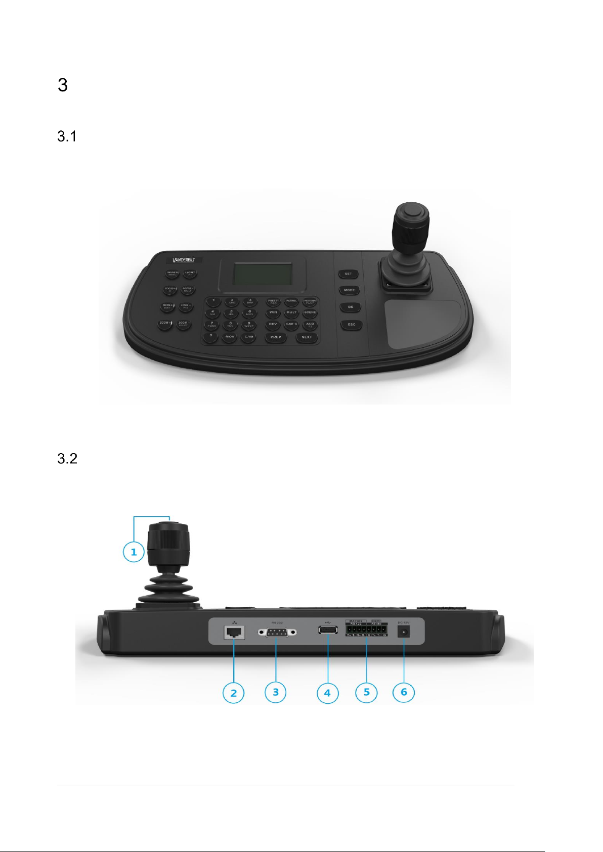
Eventys IP Keyboard
Figure 3-1 Eventys IP Keyboard
Interfaces and Joystick
Refer to Figure 3-2 Interfaces for the interfaces and joystick of the keyboard.
Figure 3-2 Interfaces
Page 11

Introduction
© Vanderbilt 2017
11
Table 3-1 Description of Rear Panel
SN
Item
Description
1
4-axis joystick
In menu mode,
1. Move to up/down to select the menu for configuration
2. Move to left/right to select items in menu.
3. When entering the value in the field, move to the left to clear the
previous character.
4. Press the central button to confirm.
In shortcut operation mode,
1. Move the joystick to realize pan/tilt movement in 8 directions. And
the PTZ speed is depending on the joystick movement range.
2. Rotate the joystick in clockwise/anti-clockwise directions to l to
realize the zoom in/out control.
3. Press the central button to capture picture.
2
LAN
10/100Mbps Ethernet Interface
3
RS-232 serial interface
Serial interface for debugging
4
USB interface
Universal Serial Bus (USB 2.0) port for additional devices such as USBflash disk
5
RS-422 serial interface
Connect with the matrix, video access gateway device, etc.
RS-485 serial interface
Connect with the speed dome unit for PTZ control
6
Power supply
12V DC Power Input
Page 12
Introduction
© Vanderbilt 2017
12
Functional Buttons
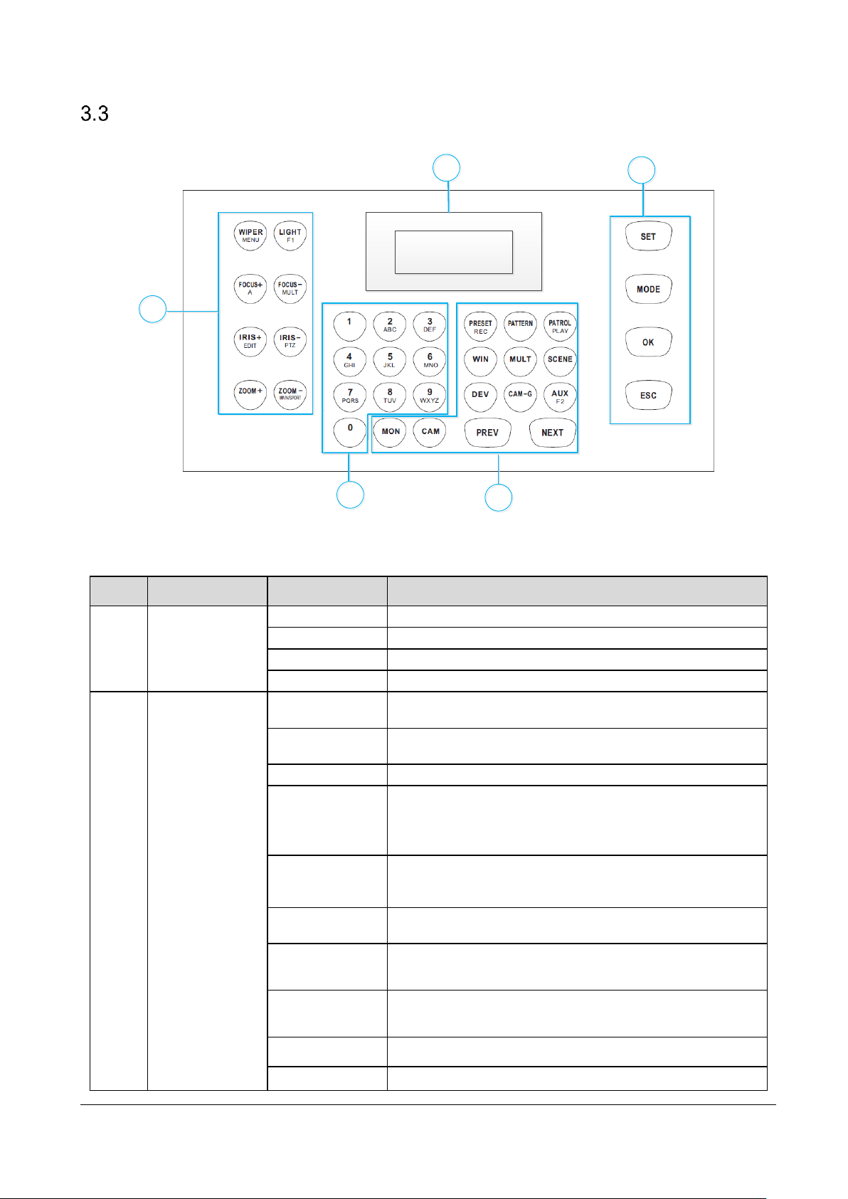
Figure 3-3 Functional Buttons
Table 3-2 Description of Rear Panel
4
1
2
3
5
SN
Item
Button
Description
1
Common Buttons
SET
Enter the main menu of the system.
MODE
Enter the 6 operation modes interface.
OK
Confirm the selection and operation.
ESC
Cancel and back to the pervious menu.
2
Video Wall
Control
(for 3rd party
product)
MON
In the shortcut operation mode, use with the numeric buttons to
select the monitor.
CAM
In the shortcut operation mode, use with the numeric buttons to
select the camera.
RRESET/REC
Use with the numeric buttons to call the preset.
PATTERN
Press PATTERN directly or 0 + PATTERN to call the auto
scanning.
Use with the numeric (>0) buttons to call the pattern.
PATROL/PLAY
Use with the numeric buttons to call the patrol.
Start playing the video files in DVR operation mode.
WIN
In the shortcut operation mode, use with the numeric buttons to
select window of video wall.
MULT
In the shortcut operation mode, use with the numeric buttons to
select the window division modes of video wall.
SCENE
In the shortcut operation mode, use with the numeric buttons to
switch the scenes.
DEV
Use with the numeric buttons to select the device ID.
CAM-G
In the shortcut operation mode, use with the numeric buttons to
Page 13

Introduction
© Vanderbilt 2017
13
select the camera group.
AUX/F2
Realize the defined auxiliary functions (picture capture or
screen jointing of video wall)
PREV
In the shortcut operation mode, switch to the previous camera
ID or camera group ID.
NEXT
In the shortcut operation mode, switch to the next camera ID or
camera group ID.
3
Alphanumeric
Buttons
0-9/A-Z
Inputs numbers and characters in edit mode.
4
PTZ Control/
DVR Control
WIPER/
MENU
In PTZ control mode, turn on/off the wiper.
In DVR operation mode, enter the main menu of DVR.
LIGHT/F1
In PTZ control mode, turn on/off the light.
In DVR operation mode, the same with the F1 button on the
DVR panel.
FOCUS+/A
In PTZ control mode, operate the focus far.
In DVR operation mode, the same with the A button on the
DVR panel.
In edit mode, switch the character input mode: numerals
(123), upper case (ABC) and lower case (abc).
FOCUS-/MULT
In PTZ control mode, operate the focus near.
In DVR operation mode, the same with the MULT button on
the DVR panel.
IRIS+/EDIT
In PTZ control mode, operate the iris open.
In DVR operation mode, the same with the EDIT button on
the DVR panel.
IRIS-/PTZ
In PTZ control mode, operate the iris close.
In DVR operation mode, the same with the PTZ button on
the DVR panel.
ZOOM+
In PTZ control mode, operate the zoom in.
ZOOMMAIN/SPOT
In PTZ control mode, operate the zoom out.
In DVR operation mode, the same with the MAIN/SPOT
button on the DVR panel.
5
LCD Display
128 x 64 pixel screen for display of menu.
Page 14

© Vanderbilt 2017
14
Getting Started
Activating Your Device
Purpose:
For the first-time access, you need to activate the device by setting an admin password. No operation is
allowed before activation. You can also activate the device via SADP as well.
Steps:
1. In the Device Activation interface, enter the admin passwords in the text field of Admin Password and
Confirm.
In edit mode, you can press the FOCUS+/A button on the keyboard panel to switch the character input
mode: numerals (123), upper case (ABC) and lower case (abc).
Figure 4-1 Activation Interface
STRONG PASSWORD RECOMMENDED We highly recommend that you create a strong password of
your own choosing (8 characters, including upper case letters, lower case letters, numbers, and special
characters) in order to increase the security of your product. And we recommend that you reset your
password regularly, especially in the high security system, resetting the password monthly or weekly can
better protect your product.
2. Click Confirm to finish the device activation.
When the device is activated, you need to adjust the date and time settings.
Logging in
Purpose:
You must log in to the device before configuring the keyboard, and operating the menu and other functions.
Local login and remote login (by Web browser) are optional.
Page 15

Getting Started
© Vanderbilt 2017
15
4.2.1 Local Login
1. In the Login interface, enter the user name in the User field.
2. Enter the password in the Pswd field.
Figure 4-2 Login Interface
3. Press the OK button to log in to the device.
In the Login dialog box, if you enter the wrong password 7 times for an admin user or 5 times for operators,
the current user account will be locked for 30 minutes.
4.2.2 Remote Login (via Web browser)
1. Open the web browser, and enter the address (https://IP address) to enter the device Login page.
Figure 4-3 Login Interface
2. Enter the user name and password.
3. Click Login to log in to the device.
Page 16

Getting Started
© Vanderbilt 2017
16
System Menu
Figure 4-4 System Menu
(MAG is for 3
rd
party product)
Shortcut
System
Version
Network
User
Change
Pswd
Add User
Edit User
Delete User
RS-485
RS-422
Hardware
Time
Maintenance
Upgrade
Import
Export
Default
Menu
Keyboard
MAG by IP
DVR by IP
MAG by RS-
422
DVR by RS-
485
Dome by
RS-485
Page 17

© Vanderbilt 2017
17
Basic Configuration
Network Access Settings
You shall acknowledge that the use of the product with the Internet access might be under network security
risks. For avoidance of any network attacks and information leakage, please strengthen your own protection. If
the product does not work properly, contact with your dealer or the nearest service center.
The network connection is provided by the Eventys IP Keyboard.
1. On the keyboard, enter the network settings menu.
System > NETWORK.
2. Use the joystick to set the DHCP OFF or ON (if supported in the network).
3. If you set the DHCP to OFF, continue to set the network parameters, including the IP Address, Gateway
and Subnet Mask.
4. Press OK to save the settings.
Device Management
5.2.1 Managing Devices by Web Browser
Purpose:
You must add the devices to the keyboard via Web browser before realizing the operation and control of the
devices on the keyboard.
1. Log in to the device.
Page 18

Basic Configuration
© Vanderbilt 2017
18
Figure 5-1 Device Management Interface
2. On the Device Management > Device List page, select a device type (IPC/IP Dome, DVR/NVR or
Decoder) and click Add to add the devices.
Figure 5-2 Add Device
3. You can add the device by IP or by IP segment. Enter the network parameters, including the IP Address,
Port, login User Name and Password.
4. Click OK to save the settings. The successfully added device is shown in the list.
Figure 5-3 Successfully Added Device
You can also click the Add SADP to add the online devices in the same network segment.
IPDome_MEGA200 is an example for a PTZ dome as 3rd party product.
Page 19

Basic Configuration
© Vanderbilt 2017
19
5.2.2 Managing Input/Output Channels
Purpose:
You can manage the import and export of input channels in batch, input group and output channels via Web
browser.
Importing and Exporting Input Channel List
1. Enter the Device Management > Input Channel > Input List page.
Figure 5-4 Import & Export of Input List
2. (optional) You can select an input channel from the list and click Edit to edit the parameters including the
input channel ID, camera name and stream type.
3. Click the Export button to export the input channel list (in excel) to the local directory.
Click the Import button to import the input channel list (in excel) from the local directory.
Managing Input Channel Group
1. Enter the Device Management > Input Channel > Input Group page.
2. Click Add Group to enter the Add Input Group page.
3. Edit the group name, set the auto-switch interval (10-10000 sec) and select the input channels from the list
to the group.
Up to 16 input groups can be added.
IPDome_MEGA200 is an example for a PTZ dome as 3rd party product.
Page 20

Basic Configuration
© Vanderbilt 2017
20
Figure 5-5 Manage Input Group
4. You can modify the group information or delete the group by Modify Group and Delete Group access.
Managing Output Channel
1. Enter the Device Management > Output Channel page.
2. You can check the output channel information, or select an output channel from the list and edit the
channel ID.
Page 21

Basic Configuration
© Vanderbilt 2017
21
User and User-related Device Management
The default user account of the device is admin (administrator), and the password is set when you start the
device for the first time. The admin user account has the permission to add and delete operator accounts and
configure user parameters, and add the related devices for the added users.
You can configure 1 administrator and 15 operator accounts.
1. On the System Management > User Management web page, click Add to enter the adding user
interface.
Figure 5-6 Add User
2. Edit the user name, enter password (strong password is highly recommended), and confirm the password.
STRONG PASSWORD RECOMMENDED–We highly recommend that you create a strong password of your
own choosing (using a minimum of 8 characters, including upper case letters, lower case letters, numbers,
and special characters) in order to increase the security of your product. And we recommend that you reset
your password regularly, especially in the high security system, resetting the password monthly or weekly can
better protect your product.
3. Select the linked device (s) from the list for the user.
4. Click OK to save the settings.
Page 22

© Vanderbilt 2017
22
Keyboard Operation
1. On the login interface, enter the user name and password to log in to the device.
Figure 6-1 Menu
2. Press the MODE button on the panel to enter the operation for different device.
Figure 6-2 Operation Mode Selection
Table 6-1 Description of Operation Mode
* MAG is an example for a Access device as 3
rd
party product
3. Use the joystick to select an operation mode and press OK button to enter the operation.
SN
Operation
Mode
Description
1
Keyboard
The keyboard can be used for managing the devices (including the IPC,
IP dome, DVR/NVR, MAG, decoder, video wall controller, etc.) for
control. The keyboard can add the devices via Web browser and assign
each of them the unique device ID, and finally manage to communicate
with and realize the video wall or PTZ control through the device
ID+command operation.
2
MAG by IP*
The keyboard can connect with the matrix access gateway, and realize
the video wall control, PTZ control, etc.
3
DVR by IP
The keyboard can connect with the DVR/NVR and remotely call the
device menu and realize PTZ control through the virtual panel.
4
MAG by
RS-422*
The keyboard can connect with the Matrix Access Gateway via RS-422
serial port, and realize the video wall control, PTZ control, etc.
5
DVR by
RS-485
The keyboard can connect with the DVR/NVR via RS-485 serial port, and
remotely call the device menu and realize PTZ control through the virtual
panel.
6
Dome by
RS-485
The keyboard can connect with the analog dome or PTZ unit via RS-485
serial port, and realize PTZ control.
Page 23

Keyboard Operation
© Vanderbilt 2017
23
Keyboard Operation
The keyboard can be used for managing the devices (including the IP dome, DVR/NVR, decoder, MAG, video
wall controller, etc.) for control. MAG & Video Wall Controller are 3rd party products supported from different
manufacturer (e.g. Hikvision).
6.1.1 Video Wall Control
Purpose:
You can select different window-division display modes for the selected output channel. The configurable
multi-division display modes depend on the decoders or video wall controller.
The 1/2/4/6/8/9/12/16/25/32/36 window-division display modes are configurable.
1. In the Keyboard operation mode, press the Num + DEV buttons on the keyboard panel to select the
device ID (decoder video wall controller).
When you enter no device ID (DEV), the first decoder (device ID: 1) is set for control by default. And if
you enter no WIN ID, the window 01 is set to play the decoded video by default.
The ID for the device (decoder) and input channel/input channel group can be viewed on the Device
Management > Device List, and Device Management > Input Channel respectively via Web
browser page. Please refer to 5.2 Device Management.
2. Press the Num + MON buttons to select the display window for the output channel.
You should use the Eventys IP Keyboard client software to select and drag the output channel to the
corresponding display window on the video wall. Please refer to the user manual of the decoder for the
details of video wall configuration and operation.
3. Press the Num + MULT buttons to set the window-division display mode for the output channel.
4. Press the Num + WIN buttons to set the sub-window to play the decoded video. The selected sub-window
ID is shown in [ID] on the interface, e.g., [02].
5. Press the Num + CAM/CAM-G buttons to select the input channel or input channel group. You can press
the PREV/NEXT buttons to switch to the previous or next camera / camera group ID.
You can press the 0 + CAM buttons to stop decoding of the current camera, or press the 0 + CAM-G buttons
to stop cycle decoding of the camera group.
Page 24

Keyboard Operation
© Vanderbilt 2017
24
Figure 6-3 Video Wall Operation
6. Operate the PTZ control on the video wall.
Move the joystick to realize pan/tilt movement in 8 directions and zoom in/out control.
Rotate the joystick in clockwise/anti-clockwise directions to l to realize the zoom in/out control.
The central button of the joystick can be used to capture picture.
You can also directly press the Num + CAM buttons or Num + AUX (set to screen jointing, refer to 6.1.4 AUX
Functions) and operate the PTZ control.
6.1.2 Preset/Patrol/Pattern Calling
The keyboard can be used to control the PTZ function of the connected IP dome camera, including the pan/tilt
movement, zoom/iris/focus adjustment, and preset/patrol/pattern calling.
1. In the Keyboard operation mode, press the Num + MON buttons to select the output channel ID.
2. Press the Num + CAM buttons to select the input channel for PTZ control.
3. Call the preset/patrol/pattern.
Press the Num + PRESET buttons on the keyboard panel to call the defined preset.
Press the Num + PATROL buttons on the keyboard panel to call the defined patrol.
Press the Num + PATTERN buttons on the keyboard panel to call the defined pattern.
You can press PATTERN directly or 0 + PATTERN to call the auto scanning.
Figure 6-4 Preset Calling
The preset/patrol/pattern must be pre-configured.
Page 25

Keyboard Operation
© Vanderbilt 2017
25
6.1.3 Scene Calling
Purpose:
For the MAG, video wall controller, and decoder added to the keyboard, you can configure the scene via the
Eventys RAS client first and follow the steps below to switch the scene.
1. In the Keyboard operation mode, press the Num + DEV buttons on the keyboard panel to select the
device ID (decoder and video wall controller).
2. Press the Num + SCENE buttons on the keyboard panel to switch to the defined scene.
The scene of the video wall must be pre-configured for the decoder via client software.
Figure 6-5 Scene Calling
6.1.4 AUX Functions
The keyboard is designed with AUX/F2 key on its panel. You are allowed to configure the AUX/F2 key to
picture capture or screen jointing functions.
Screen Jointing of Video Wall
1. Log in to the decoder or video wall controller via Web browser, and configure the video wall settings.
Please refer to the user manual of decoder or video wall controller.
2. Log in to keyboard via Web browser (https://ip address), and enter the Aux Key Settings page (System
Management > Aux Key Settings).
3. Set the Aux key function to Screen Jointing.
4. Click Save to save the settings.
Page 26

Keyboard Operation
© Vanderbilt 2017
26
Figure 6-6 Aux Key Settings
5. In the keyboard operation mode,
1) Press the Num + DEV buttons to select the device ID.
2) Press the Num + AUX/F2 buttons to operate screen jointing for the video wall.
3) Press the Num + CAM buttons to select the input channel.
Figure 6-7 Video Wall Control by AUX Key
Picture Capture
The video picture from the camera can be captured and saved in U-flash disk through the keyboard operation.
1. Log in to keyboard via Web browser (https://ip address), and enter the Aux Key Settings page (System
Management > Aux Key Settings).
2. Set the Aux key function to Capture.
3. Click Save to save the settings.
4. In the keyboard operation mode,
1) Press the Num + DEV buttons to select the device ID.
2) Press the Num + MON buttons to select the display window for the output channel.
3) Press the Num + CAM buttons to select the input channel.
5. Press the AUX/F2 button on the keyboard panel to capture the picture. The picture is saved in the USB
stick / disk in FAT32 format.
You can also use the central button of the joystick to capture the picture in keyboard operation mode.
Page 27

Keyboard Operation
© Vanderbilt 2017
27
MAG by IP
The keyboard can connect with the matrix access gateway, and realize the video wall control, PTZ control, etc.
MAG is 3
rd
party products supported from different manufacturer (e.g. Hikvision).
1. Log in to the keyboard via Web browser (https://ip address), and enter the Matrix Access Gateway
Settings page.
Figure 6-8 Matrix Access Gateway
2. Configure the parameters of the matrix access gateway. And click OK to save the settings.
3. Enter the MAG by IP operation mode on the keyboard.
4. Press the Num + MON buttons to select the display window for the output channel.
5. Press the Num + WIN buttons to set the window to play the decoded video.
6. Press the Num + CAM buttons to select the input channel group. You can press the PREV/NEXT buttons
to switch to the previous or next camera ID.
Figure 6-9 MAG by IP
For the initial use of MAG, you must use the configuration kits software to configure the input/output
channel ID of the MAG. Please refer to the user manual of MAG for details. The input/output channel ID is
used for switching on the video wall or PTZ control during keyboard operation.
7. Operate the PTZ control on the video wall. Refer to 6.1.1 Video Wall Control for details.
Page 28

Keyboard Operation
© Vanderbilt 2017
28
DVR by IP
The keyboard can connect with the DVR/NVR and remotely call the device menu and realize PTZ control
through the virtual panel.
1. Log in to the keyboard via Web browser (https://ip address), and enter the DVR/NVR device list (Device
Management > Device List > DVR/NVR).
2. Click Add to add the DVR/NVR device. Please refer to 5.2 Device Management.
Figure 6-10 DVR/NVR Management
3. Enter the DVR by IP operation mode on the keyboard.
4. Press the Num + DEV buttons on the keyboard panel to select the device ID (viewed on the Device
Management > Device List > DVR/NVR).
Figure 6-11 DVR by IP
5. Operate the buttons on the keyboard panel to realize the corresponding functions. Please refer to 3.3
Functional Buttons to check the description of the DVR control buttons.
Page 29

Keyboard Operation
© Vanderbilt 2017
29
MAG by RS-422
The keyboard can connect with the matrix access gateway via RS-422 serial port, and realize the video wall
control, PTZ control, etc. MAG is 3
rd
party products supported from different manufacturer (e.g. Hikvision).
Before you start:
Check the connection between the MAG and the Keyboard. The T+ ad T- terminals of the keyboard’s RS-422
serial port must be connected with the D+ and D- terminals of the MAG’s RS-422 serial port.
Refer to the following figure:
Figure 6-12 Connection between Cascaded Keyboards and MAG
Refer to the following figure as an example for the network cable (568B). The pin 3 and pin 4 are colored in
green-white and blue.
Figure 6-13 Network Cable
1. Enter the MAG by RS-422 operation mode on the keyboard.
2. Press the Num + MON buttons to select the display window for the output channel.
3. Press the Num + WIN buttons to set the window to play the decoded video.
4. Press the Num + CAM buttons to select the input channel.
Page 30

Keyboard Operation
© Vanderbilt 2017
30
Figure 6-14 Matrix Operation
5. You can operate the PTZ control on the video wall for the connected dome. Refer to 6.1.1 Video Wall
Control for instructions.
You can also press the Num + CAM buttons to select the input channel, and operate the PTZ control.
The MAG can be connected to the keyboard by RS-422 serial port.
For the initial use of MAG, you must use the configuration kits software to configure the input/output
channel ID of the MAG. Please refer to the user manual of MAG for details. The input/output channel ID is
used for switching on the video wall or PTZ control during keyboard operation.
Page 31

Keyboard Operation
© Vanderbilt 2017
31
DVR by RS-485
The keyboard can connect with the DVR/NVR via RS-485 serial port, and remotely call the device menu and
realize PTZ control through the virtual panel.
Before you start:
Check the connection between the DVR/NVR and the Keyboard. The T+ ad T- terminals of the keyboard’s RS-
485 serial port must be connected with the D+ and D- terminals of the KB port on the DVR rear panel
respectively.
1. Use the ClientDemo to log in to the DVR/NVR to check the remote control ID.
2. Enter the DVR by RS-485 operation mode on the keyboard.
3. Press the Num + DEV buttons on the keyboard panel to select the device ID (corresponding to the remote
ID on ClientDemo).
Figure 6-15 DVR by RS-485
4. Move the joystick and operate the buttons on the keyboard panel to realize the corresponding functions.
Please refer to 3.3 Functional Buttons to check the description of the DVR control buttons.
The baud rate, protocol and other parameters of RS-485 of the keyboard must be configured to 9600, 8, 1 and
none parity.
Page 32

Keyboard Operation
© Vanderbilt 2017
32
Dome by RS-485
The keyboard can connect with the analog dome or PTZ unit via RS-485 serial port, and realize PTZ control.
Before you start:
Check the connection between the dome and the Keyboard. The T+ ad T- terminals of the keyboard’s RS-485
serial port must be connected with the T+ and T- terminals of the dome respectively.
1. Enter the Dome by RS-485 operation mode on the keyboard.
2. Press the Num + CAM buttons to select the dome site.
3. Use the joystick and operate the buttons on the keyboard panel to realize the corresponding functions.
Please refer to 3.3 Functional Buttons to check the description of the PTZ control buttons.
Figure 6-16 Dome by RS-485
The address, baud rate, protocol and other parameters of RS-485 must be configured the same with the
dome’s RS-485 parameters.
Shortcut Operation
The device control via keyboard can be realized by shortcut operation.
1. On the login interface, enter the user name and password to log in to the device.
Figure 6-17 Menu
2. Use the joystick to select the Shortcut to enter the shortcut operation mode.
3. Press the Num+DEV/MON/CAM/CAM-G/PRESET/PATROL/PATTERN/WIN/MULT/SCENE on the
keyboard buttons to realize the corresponding device operation and control.
Page 33

© Vanderbilt 2017
33
System Menu Configuration
On the main menu after login, you can select System to check the version, and configure the system
configuration, including network, user, RS-485, RS-422, hardware, time and maintenance.
Figure 7-1 Main Menu
Refer to 5.1 Network Access Settings for the configuration of network parameters.
Version
Select Version to check the version information of the keyboard, including the firmware, panel, hardware and
software version.
User Management
1. Select User to enter the user management interface. You can change the password (admin), add new
user, edit user or delete the user.
2. Click OK button or the central button of joystick to save the settings.
Figure 7-2 User Management
Only the admin user is allowed to add/edit/user the user (operator).
Page 34

System Menu Configuration
© Vanderbilt 2017
34
RS-485/RS-422 Settings
You can connect the analog dome or DVR with the keyboard via RS-484 serial port, and the MAG with
keyboard via RS-422 serial port.
Select RS-485/RS-422 to enter the RS-485/RS-422 settings interface. You can configure the address bit (RS-
485 only), baud rate, data bit, protocol (PROT: PELCO-P, PELCO-D, VICON, KALATEL, HIKVISION-C
selectable), stop bit, parity, and copy all settings. When you set the Copy All to Yes for RS-485 serial port, the
current settings will be copied to the connection of all other RS-485 devices.
Click OK button or the central button of joystick to save the settings.
Figure 7-3 RS-485 Settings
The RS-485/RS-422 parameters configured here must be the same with the connected dome/DVR or MAG.
Hardware
You can set the auto-logoff feature of the keyboard.
Select Hardware to enter the following interface, and move (left/right) the joystick to set the A-Logoff to ON or
OFF. Click OK button or the central button of joystick to save the settings.
When the auto-logoff is set to ON, the system will automatically log off after the device is not operated for 30
minutes.
Figure 7-4 Auto-Logoff Settings
Page 35

System Menu Configuration
© Vanderbilt 2017
35
Time Settings
Select Time to enter the system time settings interface. You can set the value of year, month, date, time
format, hour, minute and second. Click OK button or the central button of joystick to save the settings.
Maintenance
Select Maintenance to enter the system maintenance settings interface. You can upgrade the device, import
and export the configuration files, and recover the device to the factory default settings.
Figure 7-5 Maintenance
You should connect the U-flash disk to the keyboard before upgrading, and importing/exporting the files.
The upgrade file and configuration file must be located in the root directory of the U-flash disk.
The upgrade file must be in digicap.dav; and the configuration file in kbCfg.bin.
Page 36

© Vanderbilt 2017
36
Appendix
Specifications
Table 8-1 Specification of Eventys IP Keyboard
Model
CKN3910
System
LCD screen
128 x 64 pixel screen
Joystick
4-axis joystick
Control mode
Network, RS-232, RS-422, RS-485
External
Interfaces
Network interface
1; 10M/100Mbps self-adaptive Ethernet interface
Serial interface
1 RS-232, 1 RS-422, 1 RS-485
USB interface
1 × USB 2.0
General
Power supply
12V DC
Consumption
≤ 4.5W
Working temperature
-10 to +55°C (14 to 131°F)
Working humidity
10% to 90%
Dimensions (W × D × H)
435 × 193 × 110mm
Weight
0.8kg
Page 37

Appendix
© Vanderbilt 2017
37
Page 38

Issued by Vanderbilt International (IRL) Ltd.
Clonshaugh Business and Technology Park
Clonshaugh
Dublin D17 KV84
Ireland
www.vanderbiltindustries.com
© Vanderbilt 2017
Data and design subject to change without notice
Supply subject to availability
Document no : C-301412
Document version: 1.0
Edition: 05.04.2017
 Loading...