

Page 1
IP 2MP Speed Dome 23x
Eventys CCDM2010-OIRD
Quick start guide
Document ID: C-301501
Edition: 01.05.2017
Page 2

Copyright
Technical specifications and availability subject to change without notice.
© Vanderbilt 2017
We reserve all rights in this document and in the subject thereof. By acceptance of the document the recipient
acknowledges these rights and undertakes not to publish the document nor the subject thereof in full or in part,
nor to make them available to any third party without our prior express written authorization, nor to use it for any
purpose other than for which it was delivered to him.
Page 3

© Vanderbilt 2017
3
Table of contents
1. About this Manual .................................................................................................................................................. 4
2 Overview ................................................................................................................................................................. 9
2.1 Overview of IP 2MP Speed Dome 23x ..................................................................................................... 9
3 Installation ............................................................................................................................................................ 10
3.1 Wall Mounting ......................................................................................................................................... 11
4 Setting the Dome over the LAN ........................................................................................................................... 16
4.1 Wiring...................................................................................................................................................... 16
4.2 Activating the Speed Dome .................................................................................................................... 16
4.3 Activation via Web Browser .................................................................................................................... 17
4.4 Activation via Eventys IP Search Tool .................................................................................................... 18
4.5 Modifying the IP Address ........................................................................................................................ 19
5 Accessing by Web Browser ................................................................................................................................ 20
Page 4

© Vanderbilt 2017
4
1. About this Manual
This Manual is applicable to IP 2MP Speed Dome 23x zoom.
The Manual includes instructions for using and managing the product. Pictures, charts, images and all other
information hereinafter are for description and explanation only. The information contained in the Manual is subject
to change, without notice, due to firmware updates or other reasons. Please find the latest version in the company
website
Please use this user manual under the guidance of professionals.
Legal Disclaimer
REGARDING TO THE PRODUCT WITH INTERNET ACCESS, THE USE OF PRODUCT SHALL BE WHOLLY
AT YOUR OWN RISKS. OUR COMPANY SHALL NOT TAKE ANY RESPONSIBILITES FOR ABNORMAL
OPERATION, PRIVACY LEAKAGE OR OTHER DAMAGES RESULTING FROM CYBER ATTACK, HACKER
ATTACK, VIRUS INSPECTION, OR OTHER INTERNET SECURITY RISKS; HOWEVER, OUR COMPANY WILL
PROVIDE TIMELY TECHNICAL SUPPORT IF REQUIRED.
SURVEILLANCE LAWS VARY BY JURISDICTION. PLEASE CHECK ALL RELEVANT LAWS IN YOUR
JURISDICTION BEFORE USING THIS PRODUCT IN ORDER TO ENSURE THAT YOUR USE CONFORMS
THE APPLICABLE LAW. OUR COMPANY SHALL NOT BE LIABLE IN THE EVENT THAT THIS PRODUCT IS
USED WITH ILLEGITIMATE PURPOSES.
IN THE EVENT OF ANY CONFLICTS BETWEEN THIS MANUAL AND THE APPLICABLE LAW, THE LATER
PREVAILS.
Page 5

© Vanderbilt 2017
5
1.1 Regulatory Information
EU Conformity Statement
This product and - if applicable - the supplied accessories too are marked with "CE" and comply
therefore with the applicable harmonized European standards listed under the EMC Directive
2014/30/EU.
2012/19/EU (WEEE directive): Products marked with this symbol cannot be disposed of as unsorted
municipal waste in the European Union. For proper recycling, return this product to your local supplier
upon the purchase of equivalent new equipment, or dispose of it at designated collection points. For more
information see: www.recyclethis.info
2006/66/EC (battery directive): This product contains a battery that cannot be disposed of as unsorted
municipal waste in the European Union. See the product documentation for specific battery information.
The battery is marked with this symbol, which may include lettering to indicate cadmium (Cd), lead (Pb),
or mercury (Hg).
For proper recycling, return the battery to your supplier or to a designated collection point. For more information
see: www.recyclethis.info
Page 6
© Vanderbilt 2017
6
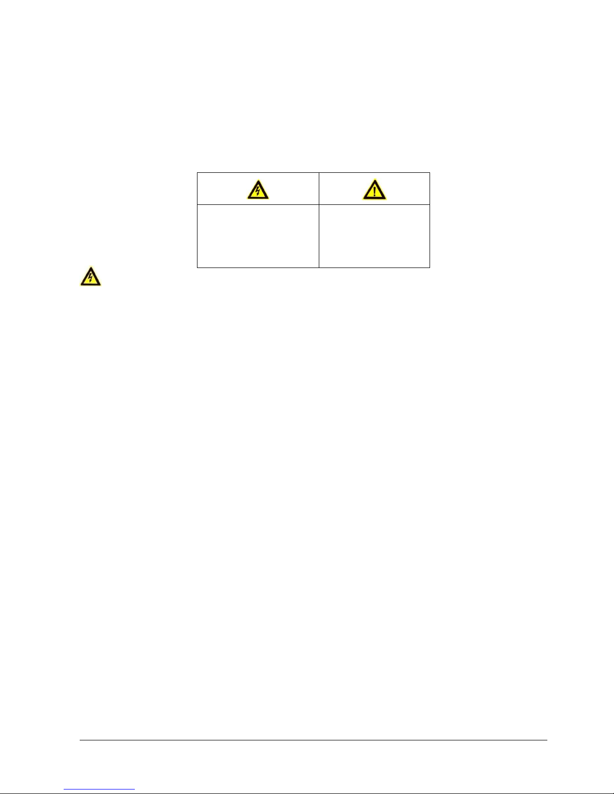
1.2 Safety Instruction
These instructions are intended to ensure that user can use the product correctly to avoid danger or property loss.
The precaution measure is divided into “Warnings” and “Cautions”
Warnings: Serious injury or death may occur if any of the warnings are neglected.
Cautions: Injury or equipment damage may occur if any of the cautions are neglected.
Warnings
● Proper configuration of all passwords and other security settings is the responsibility of the installer
and/or end-user.
● In the use of the product, you must be in strict compliance with the electrical safety regulations of the
nation and region. Please refer to technical specifications for detailed information.
● Input voltage should meet both the SELV (Safety Extra Low Voltage) and the Limited Power Source with
24VAC or
12 VDC according to the IEC60950-1 standard. Please refer to technical specifications for detailed
information.
● Do not connect several devices to one power adapter as adapter overload may cause over-heating or a
fire hazard.
● Please make sure that the plug is firmly connected to the power socket.
● If smoke, odor or noise rise from the device, turn off the power at once and unplug the power cable, and
then please contact the service center.
● It is mandatory, to fit the safety belt properly whist the installation of the dome to avoid that the dome
falls down in both cases: whilst the installation work and in normal mode of operation.
1.3 Preventive and Cautionary Tips
Before connecting and operating your device, please be advised of the following tips:
• Ensure unit is installed in a well-ventilated, dust-free environment.
• Unit is designed for indoor use only.
• Keep all liquids away from the device.
• Ensure environmental conditions meet factory specifications.
• Ensure unit is properly secured to a rack or shelf. Major shocks or jolts to the unit as a result of dropping it
may cause damage to the sensitive electronics within the unit.
Warnings Follow these
safeguards to prevent
serious injury or death.
Cautions Follow these
precautions to prevent
potential injury or
material damage.
Page 7
© Vanderbilt 2017
7
• Use the device in conjunction with an UPS if possible.
• Power down the unit before connecting and disconnecting accessories and peripherals.
• A factory recommended HDD should be used for this device.
• Improper use or replacement of the battery may result in hazard of explosion. Replace with the same or
equivalent type only. Dispose of used batteries according to the instructions provided by the battery
manufacturer.
1.4 Power Supply
• Ensure that the AC power supply is stable and within the rated voltage of the unit. Use an uninterrupted
power supply (UPS) to ensure a continuous function of the unit in the event of power dips on the AC mains
supply. Suitable UPS devices can be ordered within the local IT market, e.g. APC SMT2200I or others.
1.5 Applicable Models
This manual is applicable to the models listed in the following table.
Order number
Model
V54561-C147-A100
CCMD2010-OIRD, Eventys IP 2MP Speed Dome 23x zoom
1.6 Available accessories (for reference)
Order number
Model
N54561-M113-A100
CCMD2010-WM Wall mount
N54561-M114-A100
CCMD2010-VPM, Vertical pole mount
N54561-M115-A100
CCMD2010-CM, Corner Mount
N54561-M116-A100
CCMD2010-WMPB, Wall mount with power box
N54561-M117-A100
CCMD2010 VPMJB, Vertical pole mount with junction box
N54561-M118-A100
CCMD2010-WMJB, Wall mount with junction box
N54561-M119-A100
CCMD2010-GM Gooseneck mount
N54561-M120-A100
CCMD2010-PM Pendant mount
N54561-M121-A100
CCMD2010-PML, Pendant mount long
N54561-M122-A100
CCMD2010-CMA, Ceiling mount
N54561-M123-A100
CCMD2010-PWM, Parapet wall mount
Page 8

© Vanderbilt 2017
8
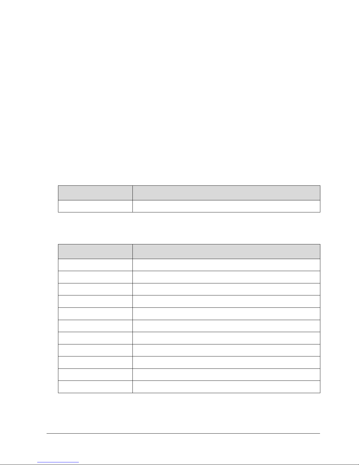
1.7 Symbol Conventions
The symbols that may be found in this document are defined as follows.
Symbol
Description
Indicates a potentially hazardous situation, which if not
avoided, could result in equipment damage, data loss,
performance degradation, or unexpected results.
Provides additional information to emphasize or supplement
important points of the main text.
Page 9

© Vanderbilt 2017
9
2 Overview
Please turn the power off before connect the cables.
The cables are distinguished by different colors. The labels attached on the cables are for identification.
The figures below are for reference only, please refer to the actual product as the standard.
2.1 Overview of IP 2MP Speed Dome 23x
1
2
3
4
5
6
7
8
9
Figure 2-1 Cable Interface of CCMD2010-OIRD
Table 2-1 Descriptions of Cable Interface
No.
Description
1
Network Cable
2
Video Cable
3
Alarm Out
4
Audio Cable
5
Alarm In
6
RS-485
7
Power Cable
8
SD Card Slot
9
Head Cover
Page 10

© Vanderbilt 2017
10
3 Installation
Before you start:
● Make sure the device in the package is in good condition and all the assembly parts are included.
● The standard power supply is 12V DC or 24V AC, please make sure your power supply matches with
your speed dome.
● Make sure all the related equipment is power-off during the installation.
● Check the specification of the products for the installation environment.
● Make sure that the wall is strong enough to withstand four times the weight of the speed dome and the
bracket.
For the speed dome that supports IR, you are required to pay attention to the following precautions to prevent IR
reflection:
● Dust or grease on the dome cover will cause IR reflection. Please do not remove the dome cover film
until the installation is finished. If there is dust or grease on the dome cover, clean the dome cover with
clean soft cloth and isopropyl alcohol.
● Make sure that there is no reflective surface too close to the lens. The IR light from the speed dome
may reflect back into the lens causing reflection.
Do not drag the speed dome with its waterproof cables as shown below, otherwise the waterproof performance
is affected.
Figure 3-1 Do not drag the cables
Page 11

© Vanderbilt 2017
11
3.1 Wall Mounting
Before you start:
Please turn off the power of the speed dome before connecting the cables.
• For cement wall, you need to use the expansion screw to fix the bracket. The mounting hole of the
expansion pipe on the wall should align with the mounting hole on the bracket.
• For wooden wall, you can just use the self-tapping screw to fix the bracket.
• Please make sure that the wall is strong enough to withstand more than 8 times the weight of the
dome and the bracket.
• The bracket in Figure 3-4 Secure the BracketFigure 3-4 is the recommended bracket for this series
of speed dome, and a pendent adapter is required if any other bracket is selected.
• It is mandatory, to fit the safety rope properly whilst the installation of the dome to avoid that the
dome falls down in both cases: whilst the installation work and in normal mode of operation.
Steps:
1 Remove the protective sticker.
Protective Sticker
Figure 3-2 Remove Protective sticker
2 Remove the cover on the back of the speed dome. Insert the SD card to the SD card slot and install
the cover back.
Page 12

© Vanderbilt 2017
12
SD Card Slot
Figure 3-3 SD Card Slot
3 Secure the bracket with 4 hex nuts and washers.
Figure 3-4 Secure the Bracket
4 Apply thread tape to the thread of the head cover and rotate the head cover to the bracket. Secure
the head cover to the bracket with set screws (supplied).
Figure 3-5 Secure the Head Cover
5 Buckle the handle to the safety rope.
Page 13

© Vanderbilt 2017
13
+
Figure 3-6 Buckle the Handle
6 Hook the two ends of the safety rope to the back box of the speed dome and the bracket respectively.
7 Hitch the speed dome onto the head cover with the hook on the back box.
Back Box
Hook
Figure 3-7 Hang the Speed Dome
Page 14

© Vanderbilt 2017
14
8 Route the cables through the head cover and bracket.
Figure 3-8 Route the Cables
9 Align the back box of the speed dome with the head cover. Use an Allen wrench to tighten the lock
screws to secure the speed dome and the bracket.
Lock Screw
Figure 3-9 Secure the Speed dome (shown Dome model as example)
10 Remove the protective film of the IR or laser light after you finish installing.
• The bracket in Figure 3-4 is the recommended bracket for this series of speed dome, and a pendent
adapter is required if any other bracket is selected.
Page 15

© Vanderbilt 2017
15
Pendant Adapter
Lock Screw
Figure 3-10Pendent Adapter
Page 16

© Vanderbilt 2017
16
4 Setting the Dome over the LAN
• You shall acknowledge that the use of the product with Internet access might be under network
security risks. For avoidance of any network attacks and information leakage, please strengthen your
own protection. If the product does not work properly, please contact with your dealer or the nearest
service center.
• To ensure the network security of the speed dome, we recommend you to have the speed dome
assessed and maintained termly. You can contact us if you need such service.
4.1 Wiring
To view and configure the speed dome via LAN (Local Area Network), you need to connect the network speed
dome in the same subnet with your PC. Then, install the Eventys IP Search Tool or client software to search and
change the IP of network speed dome.
The following figure shows the cable connection of network speed dome.
Network
Speed Dome
Switch
Internet
NVR
PC
Figure 4-1 Wiring over LAN
4.2 Activating the Speed Dome
Purpose:
You are required to activate the speed dome first by setting a strong password for it before you can use the speed
dome.
Activation via Web Browser, Activation via Eventys IP Search Tool, and Activation via client software are
supported. In the following sections, activation via web browser and Eventys IP Search Tool will be taken as
examples. You may refer to the user manual of the speed dome for the details of activation via client software.
Page 17

© Vanderbilt 2017
17
4.3 Activation via Web Browser
Steps:
1 Power on the camera, and connect the camera to the network.
2 Input the IP address into the address bar of the web browser, and click Enter to enter the activation
interface.
Notes:
• The default IP address of the camera is 192.168.0.10.
Standard User is admin
• For the camera enables the DHCP by default, you need to activate the camera via Eventys IP
Search Tool software and search the IP address.
Figure 4-2 Activation Interface(Web)
3 Create a password and input the password into the password field.
STRONG PASSWORD RECOMMENDED– We highly recommend you create a strong password of
your own choosing (using a minimum of 8 characters, including upper case letters, lower case letters,
numbers, and special characters) in order to increase the security of your product. Moreover, we
recommend you reset your password regularly, especially in the high security system, resetting the
password monthly or weekly can better protect your product.
4 Confirm the password.
5 Click OK to save the password and enter the live view interface.
Page 18

© Vanderbilt 2017
18
4.4 Activation via Eventys IP Search Tool
Eventys IP Search Tool software is used for detecting the online device, activating the camera, and resetting the
password.
Get the software from the supplied disk or the official website, and install the tool according to the prompts. Follow
the steps to activate the camera, please refer to the User Manual of Network Camera for other two activation
methods.
Steps:
1 Run the Eventys IP Search Tool to search the online devices.
2 Check the device status from the device list, and select the inactive device.
Figure 4-3 Eventys IP Search Tool Interface
Note:
The Eventys IP Search Tool software supports activating the camera in batch. Please refer to the User Manual of
Eventys IP Search Tool for details.
3 Create a password and input the password in the password field, and confirm the password.
STRONG PASSWORD RECOMMENDED– We highly recommend you create a strong password of your own
choosing (using a minimum of 8 characters, including upper case letters, lower case letters, numbers, and special
characters) in order to increase the security of your product. And we recommend you reset your password
regularly, especially in the high security system, resetting the password monthly or weekly can better protect your
product.
4 Click OK to save the password.
You can check whether the activation is completed on the popup window. If activation failed, please
make sure that the password meets the requirement and try again.
Page 19

© Vanderbilt 2017
19
4.5 Modifying the IP Address
Purpose:
To view and configure the camera via LAN (Local Area Network), you need to connect the network camera in the
same subnet with your PC. Then, install the Eventys IP Search Tool software or client software to search and
change the IP of network camera. We will take modifying the IP Address via Eventys IP Search Tool software as
an example to introduce the IP address modification.
Steps:
1 Run the Eventys IP Search Tool software.
2 Select an activate device.
Note:
Please refer to Section 4.2 to activate the camera if the camera is inactive.
3 Change the device IP address to the same subnet with your computer by either modifying the IP
address manually or checking the checkbox of Enable DHCP.
Figure 4-4 Modify the IP Address
4 Input the password to activate your IP address modification.
Eventys IP Search Tool supports the batch IP address modification. Please refer to the User Manual of Eventys
IP Search Tool for details.
Page 20

© Vanderbilt 2017
20
5 Accessing by Web Browser
System Requirement:
Operating System: Microsoft Windows 7 SP1 and above version
CPU: 2.0 GHz or higher
RAM: 1G or higher
Display: 1024×768 resolution or higher
Web Browser: Internet Explorer 8.0 and above version, Apple Safari 5.0.2 and above version, Mozilla Firefox 5.0
and above version and Google Chrome 18 and above version
Steps:
1 Open the web browser.
2 In the browser address bar, input the IP address of the network camera, and press the Enter key to
enter the login interface.
Note:
• The default IP address is 192.168.0.10.
• If the camera is not activated, please activate the camera first according to Section 4.2.
3 Input the user name and password.
The admin user should configure the device accounts and user/operator permissions properly. Delete the
unnecessary accounts and user/operator permissions.
Note:
The device IP address is locked if the admin user performs 7 failed password attempts (5 attempts for the
user/operator).
1 Click Login.
Figure 5-1 Login Interface
2 Install the plug-in before viewing the live video and managing the camera. Please follow the installation
prompts to install the plug-in.
Note:
You may have to close the web browser to finish the installation of the plug-in.
Page 21

© Vanderbilt 2017
21
Figure 5-2 Download Plug-in
3 Reopen the web browser after the installation of the plug-in and repeat steps 2 to 4 to login.
Note:
For detailed instructions of further configuration, please refer to the user manual of network camera
Page 22

Issued by Vanderbilt
Clonshaugh Business and Technology Park
Clonshaugh
Dublin 17
Ireland
D17 KV84
www.vanderbiltindustries.com
© Vanderbilt 2017
Data and design subject to change without notice
Supply subject to availability
Document no.: C-301501
Document version: 1.0
Edition: 01.05.2017
 Loading...