

Page 1

CMTC2315
TFT-LED Monitor
User Manual
Page 2

© Vanderbilt 2016
2
Liefermöglichkeiten und technische Änderungen vorbehalten.
Data and design subject to change without notice. / Supply subject to availability.
© 2016 Copyright by Vanderbilt
Wir behalten uns alle Rechte an diesem Dokument und an dem in ihm dargestellten Gegenstand vor. Der Empfänger erkennt diese Rechte
an und wird dieses Dokument nicht ohne unsere vorgängige schriftliche Ermächtigung ganz oder teilweise Dritten zugänglich machen oder
außerhalb des Zweckes verwenden, zu dem es ihm übergeben worden ist.
We reserve all rights in this document and in the subject thereof. By acceptance of the document the recipient acknowledges these rights
and undertakes not to publish the document nor the subject thereof in full or in part, nor to make them available to any third party without our
prior express written authorization, nor to use it for any purpose other than for which it was delivered to him.
Page 3

© Vanderbilt 2016
3
1 About this document .................................................................................... 4
2 Safety .............................................................................................................. 5
2.1 Target group .................................................................................................... 5
2.2 General safety precautions ............................................................................. 5
2.3 Transport ......................................................................................................... 5
2.4 Installation ....................................................................................................... 6
2.5 Operation ......................................................................................................... 6
2.6 Service and maintenance ................................................................................ 7
3 EU Directives ................................................................................................. 8
4 Product description ...................................................................................... 9
5 Technical data ............................................................................................. 10
6 Details for ordering ..................................................................................... 12
7 Scope of delivery......................................................................................... 13
8 Dimensions .................................................................................................. 14
9 Device description Safety .......................................................................... 15
9.1 Connections .................................................................................................. 15
9.2 Control elements ........................................................................................... 16
9.3 Remote control .............................................................................................. 17
9.4 Power management ...................................................................................... 18
10 Mounting ...................................................................................................... 19
11 Setting the OSD screen .............................................................................. 20
11.1 Custom .......................................................................................................... 20
11.2 Image and sound........................................................................................... 21
11.3 Picture in Picture (PiP) .................................................................................. 23
11.4 Setup ............................................................................................................. 25
12 Troubleshooting .......................................................................................... 27
13 Disposal ....................................................................................................... 28
Contents
Page 4

About this document
© Vanderbilt 2016
4
1 About this document
This document contains information on the operation of the product.
Orientation guide
[-> 3]
Cross-reference
Save
Button
<Ctrl>
Key
Tips and information
Contact
If you have questions or suggestions regarding the product or this documentation,
please contact our Technical Competence Center.
Internet: service.vanderbiltindustries.com
Vanderbilt provides training courses for all products.
Page 5

Safety
© Vanderbilt 2016
5
2 Safety
2.1 Target group
Target groups
The information in this document is intended for the following target groups:
Commissioning personnel
Configure the product at the
place of installation according to
customer-specific requirements.
Check the product operability
and release the product for use
by the operator.
Searches for and corrects
malfunctions.
Has obtained suitable specialist training for the
function and for the products.
Has attended the training courses for
commissioning personnel.
Operating personnel
Performs the procedures for
proper operation of the
product.
No particular qualification required.
Has received instruction from the operational
startup personnel.
2.2 General safety precautions
Read the general safety precautions before installing/configuring/operating the device.
Keep this document for reference purposes.
This document must always accompany the product.
Please take into account any additional country-specific, local laws, safety standards or
regulations concerning installation, operation and disposal of the product.
Liability claim
Do not connect the device to the 230 V supply network if it is damaged or any parts
are missing.
Danger of electrical shock when the device casing is open.
Only qualified personnel should open the unit.
2.3 Transport
Damage during transport
Keep the packaging material for future transportation.
Do not expose the device to mechanical vibrations or shocks.
Page 6

Safety
© Vanderbilt 2016
6
2.4 Installation
Radio interference with other devices in the environment / EMC
This is a Class A device. This equipment may cause radio interference in a
residential installation. In this case the user is encouraged to perform
appropriate measures to correct the interference.
For reasons of electromagnetic compatibility HDMI, DVI, S-Video, Audio, VGA,
Component and PC-Stereo cables must not exceed 3 meters in length.
Damage due to unsuitable mounting location
The environmental conditions recommended by the manufacturer must be
observed. See section 'technical data'.
Do not operate the device close to sources of powerful electromagnetic
radiation.
Do not operate the device in dusty places.
The device should only be used for indoor applications.
Do not expose the device to mechanical vibrations or shocks.
Protect the device against moisture.
Place the unit on a stable surface that will support its weight.
Damage to the device due to lack of ventilation
Do not block or cover the ventilation openings of the device. To ensure
sufficient ventilation please also read the instructions in the installation guide.
Danger of electrical shock/fire hazard/damage to the device due to
incorrect connection
Connect the device only to power sources with the specified voltage. Voltage
supply requirements can be found on the rating label of the device.
Danger of electrical shock due to unsuitable power source
Use only the plug-in power supply unit that is included in the delivery.
2.5 Operation
Danger of explosion or burn hazard if the battery is improperly installed
When inserting new batteries make sure the battery poles are correctly
positioned.
Do not expose the battery to fire or high temperatures.
Discard used batteries according to local regulations.
Page 7

Safety
© Vanderbilt 2016
7
2.6 Service and maintenance
Danger of electrical shock during maintenance
Do not attempt to service or modify this device yourself. Refer this work to
qualified service personnel.
Danger of electrical shock while cleaning the device
Do not use liquid cleaners or sprays that contain alcohol, spirit or ammonia.
Page 8

EU Directives
© Vanderbilt 2016
8
3 EU Directives
This product complies with the requirements of the following European directives.
The EU declaration of conformity is available to the responsible agencies at:
Vanderbilt
Clonshaugh Business and Technology Park
Clonshaugh
Dublin 17
Ireland
www.vanderbiltindustries.com
Compliance with the European Directive 2004/108/EC has been proven by testing
according to the following standards:
Emitted interference:
EN 61000-3-2
EN 61000-3-3
EN 55022 Kl. A
Interference resistance:
EN 50130-4
European Directive 2006/95/EEC “Low-Voltage Directive”
Compliance with the European Directive 2006/95/EEC has been proven by testing
according to the following standards:
Safety:
EN 60950-1
Page 9

Product description
© Vanderbilt 2016
9
4 Product description
The CMTC2315 is part of the new wide screen monitor range of Vanderbilt. The
high-resolution TFT monitor has been specifically designed for CCTV applications
and is ideally suited for use with digital video recorders (DVR) and PC applications.
Its very high contrast ratio and brightness combined with a viewing angle of 160˚
H/V provides a clear and comfortable view.
The PiP/PbP function (Picture-in-Picture/Picture-by-Picture) extends the monitor to
a real security monitor.
The monitor has two BNC video inputs with loop-through outputs, one DVI and one
HDMI input for DVR- and PC-based applications. In addition, it is equipped with 2
audio inputs and outputs and built-in speakers.
A graphical OSD menu in 5 languages and a remote control make the monitor
particularly user-friendly. The control buttons on the monitor can be passwordprotected so that tampering with the settings by unauthorized persons is prevented.
Page 10

Technical data
© Vanderbilt 2016
10
5 Technical data
Panel type
58 cm (23”) TFT colour LED panel
Viewable size (H x V)
509.76 x 286.74 mm
Pixel pitch (H x V)
0.2655 x 0.2655 mm
Viewing angle (H / V)
160° / 160°
Contrast ratio
1000:1
Brightness
250 cd/㎡
Resolution (H x V)
1920 x 1080 pixels
Colours
16.7M
Response time
5 ms
Power requirement (power supply)
100 – 240V~
Power requirement (monitor)
12 2.3A
Power consumption
28W
Scanning frequency
31 – 80 kHz (H); 56 – 75 Hz (V)
Inputs
PC
- Resolution: FHD (1920 x 1080 at 60 Hz)
- Connection: VGA, DVI-D, HDMI
VIDEO
- Standard: PAL/NTSC (auto-sensing)
- Connection: 2 x BNC (Composite Video),
- Level: 1.0 Veff., 75 Ohm terminated
AUDIO
- 1 x audio input (chinch, R+L) for AV1, AV2
- 1 x PC stereo audio input
Trigger
- 1 trigger input
Outputs
VIDEO
- 2 video outputs (BNC, looped through)
AUDIO
- Integrated loudspeakers: 2x1 W stereo
OSD languages
English, French, German, Italian, Spanish,
Portuguese, Dutch
Dimensions (W x H x D)
548 x 410 x 182 mm (with base)
548 x 330 x 55 mm (without base)
Package dimensions (W x H x D)
600 x 460 x 160 mm
Material
ABS plastic
Weight
Net weight: 4,4 kg
Gross weight: 6,6 kg
Environmental operating temperature
0 – 40 °C
Page 11

Technical data
© Vanderbilt 2016
11
Storage temperature
-20 to +60 °C
Relative humidity
Max. 80%, non-condensing
Wall mount
VESA 100
Approved battery type
AAA / 1.5 V
Approval
CE
Page 12

Details for ordering
© Vanderbilt 2016
12
6 Details for ordering
Type
Order number
Designation
Weight (total)
CMTC2315
V54573-C24-A1
58 cm LED CCTV Monitor 16:9
6,6 kg
Page 13

Scope of delivery
© Vanderbilt 2016
13
7 Scope of delivery
TFT LED monitor
External power supply unit
Power cable
DVI cable
HDMI cable
VGA cable
Audio stereo cable
Remote control (incl. batteries)
Operation manual
Page 14
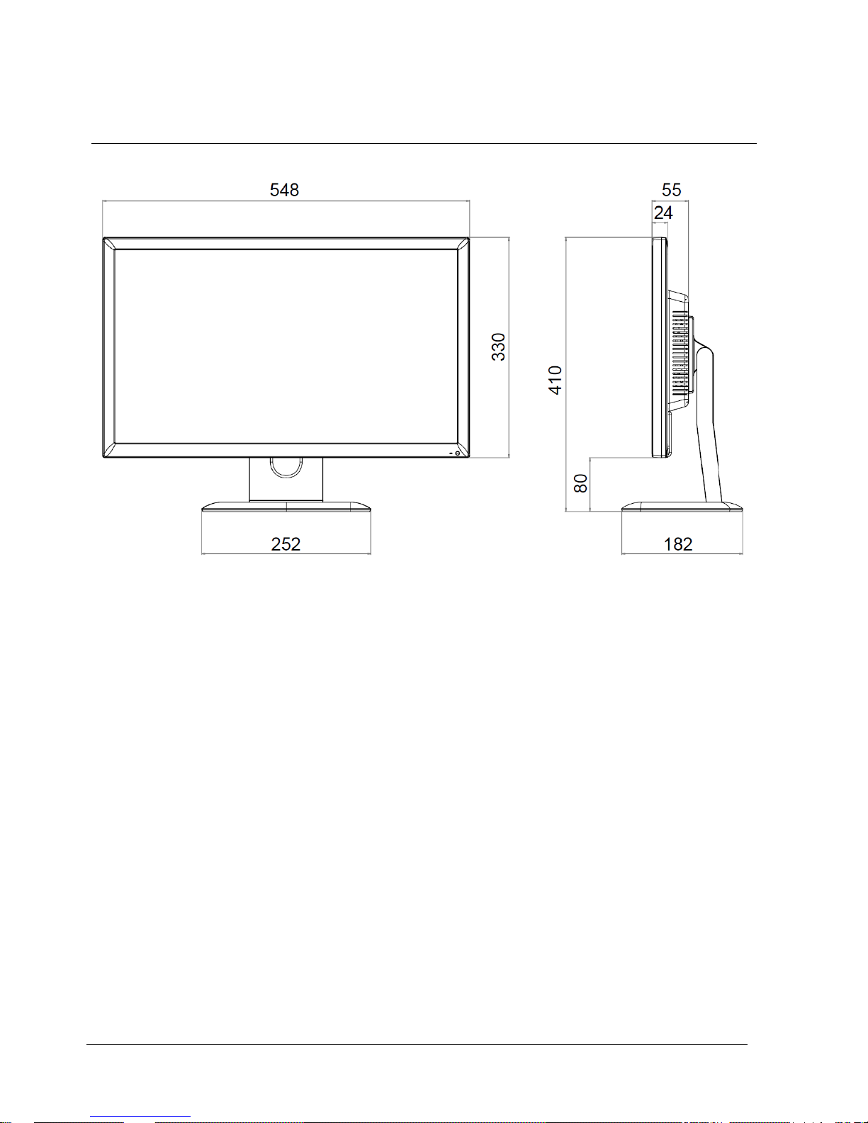
Dimensions
© Vanderbilt 2016
14
8 Dimensions
All dimensions in mm.
Page 15
Device description Safety
© Vanderbilt 2016
15
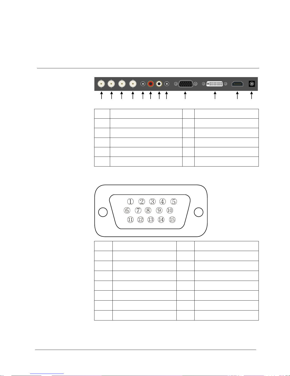
9 Device description Safety
9.1 Connections
1
Video 2 (AV2) output
8
PC Stereo input
2
Video 2 (AV2) input
9
VGA (D-SUB) input
3
Video 1 (AV1) output
10
DVI-D input
4
Video 1 (AV1) input
11
HDMI input
5
Trigger input
12
12 V DC power supply
6, 7
Audio input (R+L) for AV1, AV2
D-SUB connector pin assignments
Pin 1
Red video
Pin 9
Pin 2
Green video
Pin 10
Signal cable detect
Pin 3
Blue video
Pin 11
Update
Pin 4
Update
Pin 12
SDA (for DDC)
Pin 5
Ground
Pin 13
H-SYNC (or H/V SYNC)
Pin 6
Red ground
Pin 14
V-SYNC
Pin 7
Green ground
Pin 15
SCL (for DDC)
Pin 8
Blue ground
1 2 3 4 5 6 7 8 9
10
11
12
Page 16

Device description Safety
© Vanderbilt 2016
16
9.2 Control elements
1
SOURCE/
Selects input source (AV1/AV2/HDMI/DVI/PC)
In OSD menu: Enters sub menu
2
MENU
Enters and exits the OSD menu
In OSD menu: Exits sub menu
3, 4
AUTO/ ▼/▲
In OSD menu: Moves downward/upward in the menu
The Up button is a hold function and stops the Trigger & Auto
switching functions
5, 6
VOL ◄/►
Adjusts the volume
In OSD menu: Adjusts menu settings
7
/ I
Turns the power on or off
8
Power LED
Indicates the monitor power status
(Blue = Power is turned on; Red = Power is turned off)
9
IR sensor
Remote control sensor
1 2 3 4 5 6 7 8 9
Page 17

Device description Safety
© Vanderbilt 2016
17
9.3 Remote control
POWER: Switches the device ON or OFF
SOURCE: Selects the input source (video sources)
AUTO: Automatic geometry adjustment (only in PC mode)
HOLD: Stops the "Trigger" and "Auto Switching" functions
MUTE : Switches the sound off
MENU: Activates and closes the OSD menu
EXIT: Closes the OSD menu
VOL ◄►: Adjusts the volume
UP/DOWN: Moves up/down in the OSD menu
SOURCE/SELECT: Confirms a selection or indicates the
current operating mode
INFO: Shows information about input source and image mode
STILL: Holds the image
PIP (Picture in Picture): Activates Picture-in-Picture mode
P.INPUT: Switches the input source of the sub-image in PiP
mode
P.POS: Changes the position of the sub-image in PiP mode
P.SIZE: Changes the size of the main and the sub-image in
PiP mode
SWAP: Alternates between main image and sub-image
ARC (Aspect Ratio Control): Selects the aspect ratio
APC (Auto Picture Control): Selects the image mode
ACC (Auto Colour Control): Selects the colour mode
S.SET: Selects the sound mode in the main or sub-image
PC: Selects the PC mode (PC/DVI/HDMI)
AV: Selects the AV mode (AV1/AV2/S-VIDEO)
COMP: Selects the COMPONENT mode COMP
Page 18

Device description Safety
© Vanderbilt 2016
18
9.4 Power management
This monitor is equipped with a power management system to reduce the current
consumption after receiving a signal from a VESA DPMS-compatible video card.
The DPMS-compliant video card performs this signaling by not sending a
horizontal, vertical, or a sync signal.
Display Power Management Signaling (DPMS) is a VESA interface standard
which lowers the power consumption of computer monitors when not in use.
The monitor enters the appropriate operating mode through identifying each of the
three modes of the signaling system.
Power consumption
Mode
Power consumption
ON
< 28W
OFF
< 0.5W
LED indicator
The power management function of the monitor includes the following statuses:
Mode
LED colour
Monitor operation
ON
Blue
Normal mode
OFF
Red
No operation
Page 19

Mounting
© Vanderbilt 2016
19
10 Mounting
Wall mounting
The LCD monitor is suitable for wall mounting using a mounting fixture according to
VESA 100 Standard (not included in the delivery).
100
100
100
100
※Attention!
You must use four M4x10 screws to assemble this monitor and the wall mount
bracket.
※ Warning!
If user use longer than M4x10mm, it may cause the damage on the unit.
Please follow instructed bolt size & length.
Page 20

Setting the OSD screen
© Vanderbilt 2016
20
11 Setting the OSD screen
All image and sound settings for the monitor can be made in the OSD menu (On
Screen Display).
How to make the settings for the OSD screen:
1. Press the Menu key to select the OSD menu.
2. Select the desired option with the ▲/▼ buttons.
The selected option is highlighted.
3. Press the ▶ key to select the submenu for the settings.
4. Change the desired value with the ▲/▼ keys.
5. Press the ◀ key to exit the submenu again.
6. Press the Menu key to exit the OSD menu.
The OSD menu then disappears.
All settings are saved automatically.
NOTICE
The OSD menu disappears automatically after no settings are made after a
certain time.
11.1 Custom
"Custom" menu in video mode; "Custom" menu in RGB-PC or HDMI mode
Option
Function
Values
Brightness
Adjusts the screen brightness
0 – 100
Page 21

Setting the OSD screen
© Vanderbilt 2016
21
Option
Function
Values
Contrast
Adjusts the screen intensity
0 – 100
Color *
Adjusts the screen color
0 – 100
Tint **
Adjust the screen color tint
0 – 100
Sharpness *
Adjusts the image sharpness
0 – 100
*
only in video mode
** for NTSC only
11.2 Image and sound
"Picture/Sound" menu in video mode; "Picture/Sound" menu in RGB mode
Option
Function
Values
Picture Mode
Sets the image mode
See table below
Color Tone
Adjust the color tone
See table below
Mute
Deactivates the speaker sound
On, Off
Volume
Adjusts the volume
0 – 100
Size
Adjusts the image size
See table below
NR *
Reduces image noise
On, Off
3D Comb *
Sets the 3D comb filter
On, Off
PC **
Sets the PC input parameters
See table below
*
only in video mode
** only in RGB-PC mode
Picture Mode
Page 22

Setting the OSD screen
© Vanderbilt 2016
22
Custom
Applies user-defined values (brightness, contrast, color, tint, sharpness)
Dynamic
Provides enhanced contrast and sharpness
Standard
Provides normal contrast and normal sharpness
Movie
Recommended for watching movies
Mild
Reduces contrast and sharpness
Color Tone
Cool
Adds a bluish tone to white colors
Normal
Adds a neutral tone to white colors
Warm
Adds a reddish tone to white colors
User
To adjust the color tones (red, green, blue) manually
Size
4:3
Sets the image size to "4:3"
Panorama *
Sets the image to "Panorama"
Zoom1 *
Expands the image size about 2 times in upward and downward direction
Zoom2 *
Expands the image size about 1.5 times in upward and downward direction
Wide
Sets the image to "Wide"
Under **
Adjusts the image size to display resolution without overscan
1:1 *
Displays the image with its original resolution size
*
only in video mode
** not available in RGB-PC
PC
Auto Adjust
Automatic geometry adjustment
Phase
Defines the number of horizontal pixels
H.Position
Defines the horizontal image position
V.Position
Defines the vertical image position
Frequency
Defines the vertical image frequency
Page 23

Setting the OSD screen
© Vanderbilt 2016
23
11.3 Picture in Picture (PiP)
Menu "PIP"
Option
Function
Values
PIP
Activates Picture-in-Picture mode
On, Off
Input Source
Selects the input source for the PiP area
See table below for available/unavailable PiP
combinations
Video1, Video2,
RGB PC, DVI,
HDMI
PIP Mode
Enables 3 screen sizes
See table below
PIP Size
Selects the size of the PiP screen
See table below
Position
Selects the position of the PiP screen
See table below
Swap
Alternates between main image and sub-image
–
Sound Select
Selects the sound source from either the main image
or the sub-image
Main, Sub
Input Source
Main image
Sub-image
Available combinations
AV1 or AV2
AV1 or AV2
AV1 or AV2
RGB PC, DVI or HDMI
RGB PC, DVI or HDMI
AV1 or AV2
Unavailable combination
RGB PC, DVI or HDMI
RGB PC, DVI or HDMI
Page 24

Setting the OSD screen
© Vanderbilt 2016
24
PIP Mode
PIP
Sub
image
Main image
Sub-image (4:3) in any corner of the main
image
PBP1
Main
image
Sub
image
Side by side (4:3)
PBP2
Main
image
Sub
image
Full screen, side by side
PIP Size
Size1
Small PiP image
Size2
Medium PiP image
Size3
Large PiP image
Position
RB
Bottom right
LB
Bottom left
LT
Top left
RT
Top right
Page 25

Setting the OSD screen
© Vanderbilt 2016
25
11.4 Setup
"Setup" menu
Option
Function
Values
Reset
Resets the monitor settings to the default values
–
Language
Sets the language of the OSD menu
English, Français,
Deutsch, Italiano,
Español, Portugues,
Nederland
OSD Tone
Changes the background color of the monitor
menus (e.g. input source, information)
Transparency, On
Blue Screen
Displays a blue screen when the monitor does
not receive a signal
On, Off
Key Lock
Locks all keys of the monitor
Note: To unlock the keys use the remote control
On, Off
Trigger
Enables the trigger function
See table below
Auto
Switching
Sets the auto-switching settings
See table below
Page 26

Setting the OSD screen
© Vanderbilt 2016
26
Trigger
"Setup" menu – "Trigger" option
Trigger Enable
Enables/disables the trigger function
Trigger Input
Selects the input source for the trigger
Buzzer
Not available
Trigger Time
Selects the time period (3 – 100 s) during which the monitor displays the
trigger input image.
Trigger Option
Selects the type of physical trigger input
N/C (Normally Closed): The trigger function is activated when the trigger
cable is opened.
N/O (Normally Open) and Low: The trigger function is activated when
the trigger cable is closed.
High: The trigger function is activated when the trigger signal is DC 2 - 5
[V].
Low: The trigger function is activated when the trigger signal is DC 0 -
0.6 [V].
Display Type
Selects the mode in which the monitor displays the trigger input.
PIP&FULL: Displays the trigger input in the PiP mode of the current
video input source.
Note: The main video source must support the trigger input source as a
PiP option.
FULL: Switches the display to show the trigger input in full screen mode.
Auto Switching
Auto Switching
Activates the Auto Switching feature
Input Enable
Selects the input sources to include in the Auto Switching cycle
Time
Selects the time period (3 – 100 s) during which the monitor displays
each selected input source
Page 27

Troubleshooting
© Vanderbilt 2016
27
12 Troubleshooting
Problem
Troubleshooting tip
No image
1. Ensure that the power cable of the monitor
has been properly connected to an outlet or a
grounded outlet strip.
2. Ensure that the power switch is in ON
position and the LED is lit.
3. Ensure that brightness and/or contrast of the
display have been adjusted correctly.
Message on screen "NO SIGNAL"
1. Ensure that the signal cable is correctly
connected to the video card/computer.
2. Ensure that the video card has been correctly
inserted in the slot and the computer is
switched on.
The image in the PC mode is not centered, too
small or too large
Press the "Down" key on the front or the "Auto"
key on the remote control.
The image shows vertical or horizontal
interferences
Set clock and phase in the OSD menu.
Page 28

Disposal
© Vanderbilt 2016
28
13 Disposal
All electrical and electronic devices must be disposed of separately from the
general domestic waste through federally mandated agencies.
If this symbol of a crossed out waste bin is affixed to a product then this
product is subject to the European Directive 2002/96/EC.
The proper disposal and sorted collection of end-of-life appliances serves
the prevention of potential environmental and health damages. They are a
prerequisite for the reuse and the recycling of used electrical and electronic
devices. Detailed information about the disposal of your used devices can
be obtained at your municipality, your garbage disposal service or the
dealer where you have purchased the product.
Page 29

Disposal
© Vanderbilt 2016
29
Page 30

Issued by Vanderbilt
Clonshaugh Business and Technology Park
Clonshaugh
Dublin 17
Ireland
www.vanderbiltindustries.com
© Vanderbilt 2016
Data and design subject to change without notice
Supply subject to availability
Document no.: C-300925
Document version: 2.0
Edition: 17/2/20163/3/2016
 Loading...