

Page 1
© Vanderbilt 2016
1
CFMW3025
3 Megapixel IP Indoor Dome
Camera
Configuration
Page 2

© Vanderbilt 2016
2
Contents
1 Copyright ................................................................................................. 4
2 About this document .............................................................................. 5
2.1 Content of document ................................................................................. 5
2.2 Meaning of symbols .................................................................................. 5
2.3 Target group .............................................................................................. 5
3 Safety ........................................................................................................ 6
3.1 General safety precautions ....................................................................... 6
3.2 Transport ................................................................................................... 6
3.3 Installation ................................................................................................. 6
3.4 Maintenance .............................................................................................. 6
3.5 Sensor characteristics ............................................................................... 7
4 EU-directives ........................................................................................... 8
5 Technical data ......................................................................................... 9
6 Details for ordering ............................................................................... 10
6.1 Package contents .................................................................................... 10
7 Camera part and connector definition ................................................ 11
7.1 Camera part definition ............................................................................. 11
7.2 Connector pin definition .......................................................................... 11
7.2.1 Digital I/O terminal ................................................................................... 11
7.2.2 Power terminal ........................................................................................ 12
7.2.3 Video out connector ................................................................................ 12
7.2.4 Default/Reset buttons .............................................................................. 12
7.2.5 SD card ................................................................................................... 12
8 Installing the camera ............................................................................ 13
8.1 Precautions ............................................................................................. 13
8.1.1 SD memory card ..................................................................................... 13
8.1.2 Power supply ........................................................................................... 13
8.2 Concept of the network camera .............................................................. 14
8.3 Setting network camera environment ..................................................... 14
8.4 Connecting the camera and personal computer via network .................. 14
8.5 Using the camera search application "Webcam IP Manager" ................ 16
8.6 Login dialog ............................................................................................. 18
8.7 Viewing and listening .............................................................................. 19
8.8 Resolution ............................................................................................... 24
9 Configuration ......................................................................................... 25
9.1 Compression ........................................................................................... 25
9.2 Network settings ...................................................................................... 26
9.2.1 Basic ........................................................................................................ 26
9.2.2 DDNS Settings ........................................................................................ 28
9.2.3 FTP Server .............................................................................................. 28
9.2.4 RTSP ....................................................................................................... 29
9.2.5 HTTPS ..................................................................................................... 29
9.2.6 IEEE802.1X ............................................................................................. 30
9.2.7 SNMP ...................................................................................................... 31
9.2.8 3GPP ....................................................................................................... 31
9.3 Image parameter ..................................................................................... 32
9.3.1 Basic camera settings ............................................................................. 32
9.3.2 Camera mask zone settings.................................................................... 35
9.3.3 Camera cropping settings ....................................................................... 37
9.3.4 Camera OSD settings ............................................................................. 37
Page 3

© Vanderbilt 2016
3
9.4 Alarm ....................................................................................................... 39
9.4.1 Alarm ....................................................................................................... 39
9.4.2 Audio event upload ................................................................................. 43
9.4.3 Alarm server ............................................................................................ 44
9.5 Record ..................................................................................................... 46
9.5.1 Basic ....................................................................................................... 46
9.5.2 FTP Recording Basic .............................................................................. 47
9.5.3 SD recording ........................................................................................... 49
9.5.4 Email recording ....................................................................................... 50
9.5.5 NAS recording ......................................................................................... 54
9.6 Audio ....................................................................................................... 55
9.7 Date / Time .............................................................................................. 56
9.8 Access protection .................................................................................... 57
9.8.1 Administrator ........................................................................................... 57
9.8.2 User list ................................................................................................... 58
9.9 Firewall .................................................................................................... 58
9.9.1 IP Address filter ....................................................................................... 58
9.9.2 Forbidden ports ....................................................................................... 60
9.9.3 Forbidden protocols ................................................................................ 60
9.10 System .................................................................................................... 61
9.10.1 Settings ................................................................................................... 61
9.10.2 Update ..................................................................................................... 62
9.10.3 Configuration ........................................................................................... 63
9.10.4 Back focus ............................................................................................... 64
9.10.5 Temperature ............................................................................................ 64
9.10.6 Calibration ............................................................................................... 64
9.10.7 Self-Testing ............................................................................................. 65
9.11 Log .......................................................................................................... 66
9.12 Notice ...................................................................................................... 66
10 Utility program application .................................................................. 67
10.1 NAS player setup .................................................................................... 67
10.2 Audio recording setup ............................................................................. 67
10.3 Firmware update setup ........................................................................... 67
11 Maintenance .......................................................................................... 69
12 Disposal ................................................................................................. 70
Keyword index ....................................................................................................... 71
Page 4

Copyright
© Vanderbilt 2016
4
1 Copyright
Liefermöglichkeiten und technische Änderungen vorbehalten.
Data and design subject to change without notice. / Supply subject to availability.
© 2017 Copyright by Vanderbilt
Wir behalten uns alle Rechte an diesem Dokument und an dem in ihm dargestellten Gegenstand vor. Der Empfänger erkennt diese Rechte
an und wird dieses Dokument nicht ohne unsere vorgängige schriftliche Ermächtigung ganz oder teilweise Dritten zugänglich machen oder
außerhalb des Zweckes verwenden, zu dem es ihm übergeben worden ist.
We reserve all rights in this document and in the subject thereof. By acceptance of the document the recipient acknowledges these rights
and undertakes not to publish the document nor the subject thereof in full or in part, nor to make them available to any third party without
our prior express written authorization, nor to use it for any purpose other than for which it was delivered to him.
Page 5

About this document
© Vanderbilt 2016
5
2 About this document
2.1 Content of document
This document contains information on the configuration of the product.
2.2 Meaning of symbols
Orientation guide
[-> 3] Cross-reference
Save Button
<Ctrl> Key
Tips and information
2.3 Target group
Commissioning personnel
Configure the product at
the place of installation according to customer-specific requirements.
Check the product opera-
bility and release the product
for use by the operator.
Searches for and corrects
malfunctions.
Has obtained suitable specialist training
for the function and for the products.
Has attended the training courses for
commissioning personnel.
Operating personnel
Performs the procedures
for proper operation of the
product.
No particular qualification required.
Has received instruction from the opera-
tional startup personnel.
Page 6

Safety
© Vanderbilt 2016
6
3 Safety
3.1 General safety precautions
Read the general safety precautions before in-
stalling/configuring/operating the device.
Follow all warnings and instructions marked on the device.
Keep this document for reference purposes.
This document must always accompany the product.
Liability claim
Use only spare parts and accessories that have been approved by the
manufacturer.
3.2 Transport
Keep the packaging material for future transportation.
Do not expose the device to mechanical vibrations or shocks.
3.3 Installation
It is recommended that all preparatory work (e.g. fitting of accessories)
be carried out in a workshop prior to final installation.
The environmental conditions recommended by the manufacturer must
be observed. See section 'technical data'.
Do not operate the device close to sources of powerful electromagnetic
radiation.
The device should only be used for indoor applications.
The mounting surface must be solid and non-combustible.
Danger of electrical shock/fire hazard/damage to the device due
to incorrect connection
Connect the device only to a power source that complies with SELV
requirements and with the Limited Power Source requirements to EN
60950-1.
3.4 Maintenance
Do not attempt to service or modify this device yourself. Refer this work
to qualified service personnel.
Do not use liquid cleaners or sprays that contain alcohol, spirit or am-
monia.
Page 7

Safety
© Vanderbilt 2016
7
3.5 Sensor characteristics
The following conditions may be observed when using a CMOS camera. These
are inherent in the design and do not stem from any fault in the camera itself.
Vertical smear:
This phenomenon occurs when viewing a very bright object.
Patterned noise:
This is a fixed pattern, which may appear over the entire monitor screen
when the camera is operated at a high temperature or in a low luminance
environment.
Jagged picture:
When viewing stripes, straight lines, or similar patterns, the image on the
screen may appear jagged.
Page 8

EU-directives
© Vanderbilt 2016
8
4 EU-directives
This product complies with the requirements of the following European directives.
The EU declaration of conformity is available to the responsible agencies at:
Vanderbilt
Clonshaugh Business and Technology Park
Clonshaugh
Dublin 17
Ireland
www.vanderbiltindustries.com
European Directive 2004/108/EC „Electromagnetic Compatibility”
Compliance with the European Directive 2004/108/EC has been proven by
testing according to the following standards:
Emitted interference:
EN 55022
Interference resistance:
EN 55024
Page 9

Technical data
© Vanderbilt 2016
9
5 Technical data
Model
CFMW3025
Type
3 Megapixel IP Indoor Dome Camera
Image Sensor
1/3” AR0330 CMOS
Lens Mount
D19
Lens Type
Motorized 3~9mm
F No
1.2
Angle of View
Wide: 84°(H), 62°(V)
Tele: 30°(H), 22°(V)
Day / Night
Mechanical ICR
Digital Noise Reduction
3D
Minimum Illumination
F:1.2, CL: 0.3 lux@ 50IRE,
B/W: 0.1 lux@ 50IRE, 1/30
Audio In/Out
Audio In/Out
Alarm In/Out
Alarm In*3 / Alarm Out*1
On-board Storage
SD/SDHC slot
Video Compression
H.264 / MJPEG
Video Streaming
Triple streaming
Frame Rate
NTSC: 1080P(1920x1080) @30 fps ;
3M(2048x1536) @15 fps
PAL: 1080P(1920x1080) @25 fps ;
3M(2048x1536) @12 fps
Resolutions
2048x1536(QXGA), 1920x1080(1080P),
1280x720(720P), 720x480(480P),
640x480(VGA), 352x240(CIF),
320x240(QVGA)
Network Protocols
IPv4, HTTP, TCP/IP, RTSP, RTP, RTCP,
ICMP, UDP, IGMP, NTP, SMTP, FTP,
UPnP, DNS, DDNS, DHCP, ARP, SNMP,
IPv6, CIFS, NFS, IEC802.1x, Bonjour
WDR
Digital WDR
Motion Detection
Yes
Privacy Zones
Yes, 4 zones
Users
1 Administrator, 100 Users or Advanced
User
ONVIF
ONVIF compliance test tool pass
Web Browsing Requirements
Internet Explorer IE8 / IE9 / IE10, Firefox
Google chrome,
Connectors
Power In: terminal block/RJ45
Network: RJ-45 connector
Audio in/out: Spring Terminal
Alarm in/out: Spring Terminal
Power Requirement
DC12V(600 mA)
AC24V[450mA(PF=0.5)]
PoE IEEE 802.3af ; Class 0
Operating Temperature
-10°C ~ 50°C
Page 10

Details for ordering
© Vanderbilt 2016
10
6 Details for ordering
Type
Order No.
Designation
CFMW3025
V54561-C107A200
3 Megapixel IP Indoor Dome Camera
Further products and accessories can be found in the internet:
https://is.spiap.com/products/video.html
6.1 Package contents
IP dome camera
Video cable
2 anchors
2 screws
Template
4 GB SD card (in box)
Installation instruction
Utilities CD (including software and documentation)
Page 11
Camera part and connector definition
© Vanderbilt 2016
11
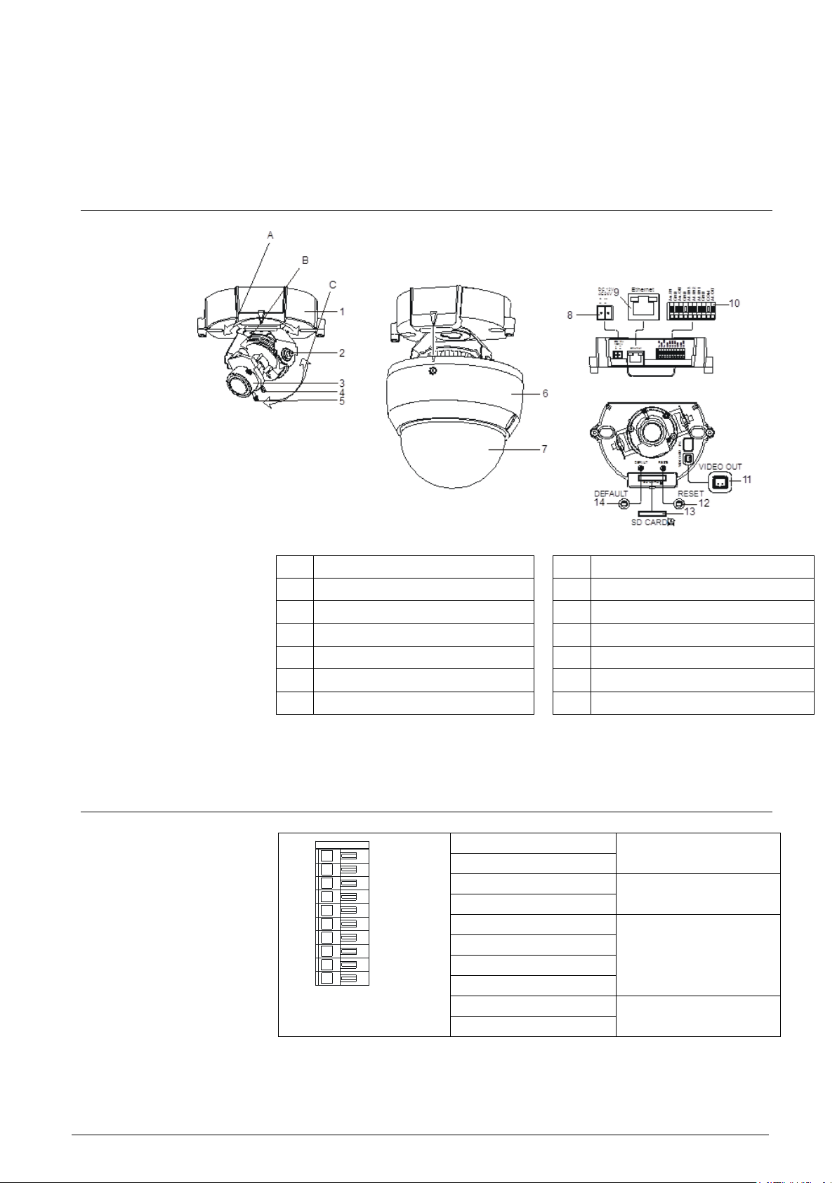
7 Camera part and connector definition
7.1 Camera part definition
1
Camera base
8
Power supply port
2
Adjusting mechanism
9
Ethernet connector
3
Lens
10
I/O terminal
4
Focal length ring
11
Video output
5
Focus ring
12
Reset button
6
Camera housing
13
SD card
7
Dome cover
14
Default button
7.2 Connector pin definition
7.2.1 Digital I/O terminal
Au.IN
GND
Au.OUT
GND
AI.IN3
AI.IN2
AI.IN1
GND
COM
AI.OUT
Au.IN
Audio in
GND
Au.OUT
Audio out
GND
AI.IN3
Alarm in
AI.IN2
AI.IN1
GND
AI.COM
Alarm out
AI.OUT
Page 12

Camera part and connector definition
© Vanderbilt 2016
12
7.2.2 Power terminal
Power terminal
DC 12 V / AC 24 V power
terminal
7.2.3 Video out connector
Video Signal Output
Composite video output
7.2.4 Default/Reset buttons
DEFAULT
Return to factory default
by pressing button (after
5 Sec)
RESET
System restart
7.2.5 SD card
SD CARD
SD CARD
To record images when
alarm events happen.
Page 13

Installing the camera
© Vanderbilt 2016
13
8 Installing the camera
8.1 Precautions
8.1.1 SD memory card
NOTICE
Please install the SD memory card before switching on the camera.
The system cannot detect an SD card that is inserted during operation.
The camera supports SD and SDHC cards.
Physical interface: Part 1. Physical Layer Specification; Version 1.01.
Images may not be recorded or read correctly if an unsupported SD
card is used with the camera.
A SD card can be used for loop recording of images. The life-span
(number of re-writes possible) of a SD card depends on its capacity. For
loop recording, it is recommended to use a large-capacity SD card.
Do not use a card containing the data recorded by another device with
the camera as this may result in the camera not functioning correctly.
Do not modify or overwrite the data, or change the folder name of a SD
card. This may result in the camera not functioning correctly.
Data recorded with the camera does not comply with the image file
format Exif and the DCF standard. If the SD card is to be removed to play
images, use a personal computer for this purpose. Other devices may not
be capable of displaying the images.
Use only new SD cards that were delivered by the manufacturer.
8.1.2 Power supply
Be sure to use only a suitable power adapter. Using the wrong type of power
adapter may cause the camera to malfunction, heat up, or catch fire. Before using the power adapter, carefully read and observe the Work safety information
and the notes below.
Do not allow the connectors on the power adapter to come into contact
with any other metal objects as this may result in short-circuit.
To connect the power adapter, firmly insert the plug end of the cable in-
to the power terminal. Do not insert the plug into other jacks as this may
cause malfunctioning.
When removing the connection cable, disconnect it by pulling the plug.
Do not pull on the cable.
Do not drop the power adapter or subject it to strong impact.
Do not use the power adapter in hot and humid places.
Temperature increase on the surface of the adapter is normal. Before
moving the adapter to another location, unplug it from the wall outlet, and
wait until its temperature decreases.
Buzzing noises may come from inside. This does not indicate malfunc-
tion.
Using the power adapter near a radio, TV, or cell phone may cause in-
terference. Use the adapter at sufficient distances from these devices.
Page 14
Installing the camera
© Vanderbilt 2016
14
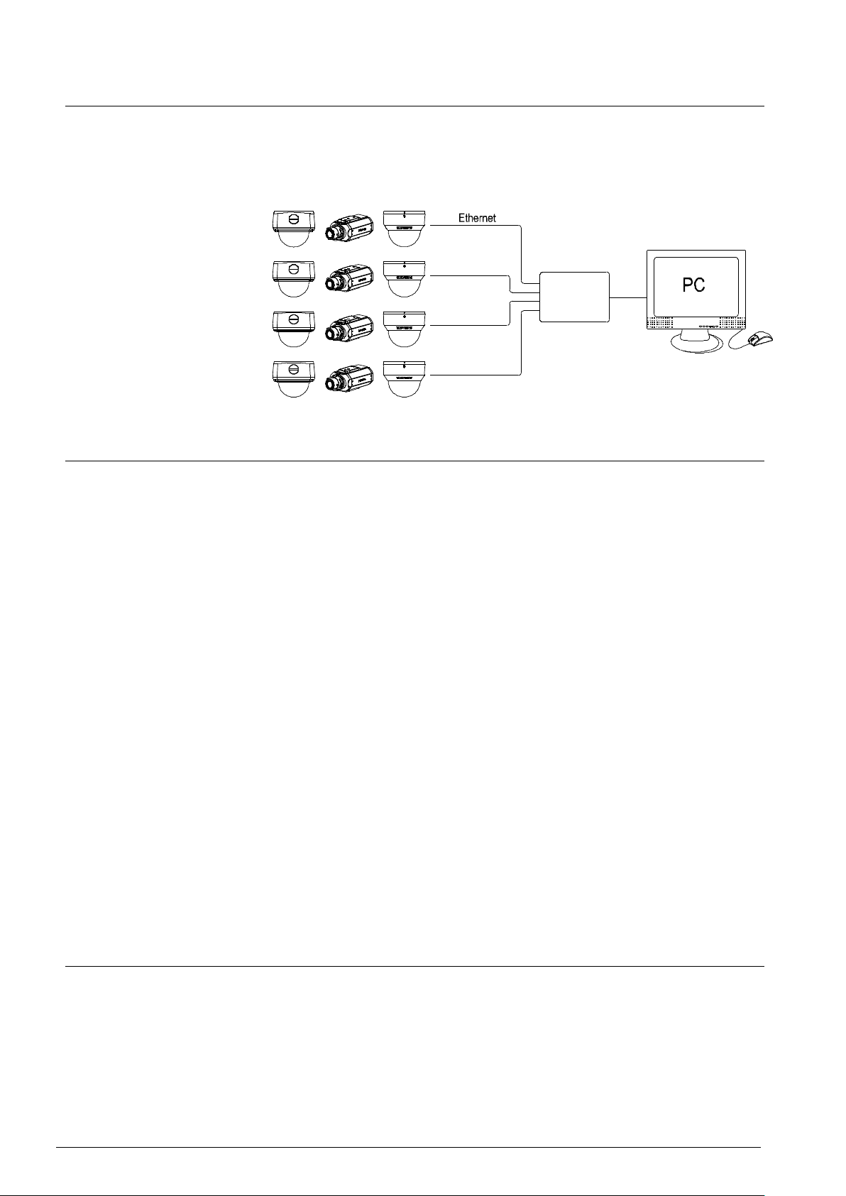
8.2 Concept of the network camera
The network camera can deliver video images and audio in real time using the
Internet or an intranet. The camera is equipped with Ethernet (RJ-45) 10BASET/100BASE-TX network interfaces.
It can be used in various indoor environments.
Switch
8.3 Setting network camera environment
Items needed for network camera monitoring system
Administrator's personal computer The personal computer that is given
all authorities for setting, operating, monitoring and other functions with the
network cameras is called the "administrator's personal computer" in this
manual.
PC requirements
– Windows Vista , XP, Win7 or Win8 as OS
– Internet Explorer IE 8.0 / IE 9.0 / IE 10.0, Firefox, and Google chrome
– CPU: Intel Pentium 4,2 GHz or higher
– Memory: 1 GB or more
Network camera
Please purchase the appropriate number of cameras required for your application.
Connection equipment such as a hub and router suiting the network
system environment, as well as a LAN cable (Cat 5e cable is recommended).
Camera search application "Webcam IP-Finder" Install this application
from the CD-ROM supplied as an accessory.
1. Double-click "ipfinder_Setup.exe" in the CD-ROM
2. install the application following the instructions on the screen
8.4 Connecting the camera and personal computer via network
IP address
To connect to the network, the administrator needs to set the network camera
IP address. There are two options to set the IP address.
Entering an IP address manually (factory default)
Obtaining an IP address automatically from the DHCP server
Entering the IP address manually.
Your camera is set to this mode at the factory with IP address 192.168.0.10, so
Page 15

Installing the camera
© Vanderbilt 2016
15
you need to enter this IP address manually to access the camera for the first
time
Obtaining an IP address automatically from the DHCP server
If your network uses a DHCP server, you do not need to change the IP address
of the camera. To activate this function, the option DHCP must be selected in
the "Network/Basic Settings".
The IP address of the network camera can be changed from time to time
when the DHCP server is used. For this reason, it may not be possible to
connect a network camera due to an IP address change if the network camera is accessed using the previously set IP address.
To enable accessing the network camera in this case, a fixed IP address needs
to be assigned manually to the network camera. Make sure to read the instruction manuals for the network equipment, as well as the manuals for the router,
hub and modem.
To manually select the basic network settings, "Manual" must be selected and
the IP address, subnet mask, default gateway, primary DNS and secondary
DNS have to be entered.
Connection configuration
There are two configuration options for connecting network cameras:
Crossover connection
Connection via a hub, switch, or router
You do not need to assign an IP address to a hub. The default IP address of
your camera is 192.168.0.10. Set the IP address of your personal computer in
the same subnet. (The network segment must be the same segment when
directly connecting using a cross-over cable or connecting via the hub). When
connecting more than one camera, connect the cameras one by one and assign an unused IP address to each one.
You can also use the LAN port of your broadband router. However, when using
the broadband router while the DHCP server function is enabled, turn on the
power after connecting the camera to the router. The camera gets the IP address from the router's DHCP server. The IP address will not be 192.168.0.10.
For more information, refer to the user documentation for your computer.
Connecting camera and personal computer
1. Connecting the LAN cable
Connect the LAN cable (straight cable) to the camera and to the hub. Alternatively, connect the camera to a personal computer using the LAN cable (cross-over cable).
2. Turning Power on
Connect DC12 V /AC 24 V to the power terminal.
Setting the IP address of the personal computer.
Use a free IP address (other than 192.168.0.10, which is the camera's
IP address).
For example, set the IP address to 192.168.0.20 (and the subnet mask
to 255.255.255.0).
For details on the procedure, refer to the user guide for the personal
computer.
Testing the camera connection using ping.
Start a command prompt. Type "ping 192.168.0.10" and press "Enter".
If the "Reply from..." message appears, the connection is correctly es-
tablished.
Search for the camera using the "Webcam IP Manager" and view a camera
Page 16

Installing the camera
© Vanderbilt 2016
16
image. See Section 6.5.
1. Start "Webcam IP Manager" and click "Search".
2. Check whether the camera name "nwcam05" is displayed in the cam-
era list.
3. Click "nwcam05" to select the camera.
The camera name, IP address and HTTP port number are displayed in
the "Network Camera Lists" field.
4. Double-click the camera you wish to log in to in the camera list.
The screen for entering the user name and password will appear.
5. Enter the administrator log-in ID and password. See "Login dialog".
A camera image screen of the network camera will appear.
To view images without using "Webcam IP Manager," launch the Internet
browser, enter URL http://192.168.0.10/ in the address box and press "ENTER."
It takes about 10 seconds to activate the camera.
If a port number other than "80" is set, enter the port number after ":" as in
http://192.168.0.10:88.
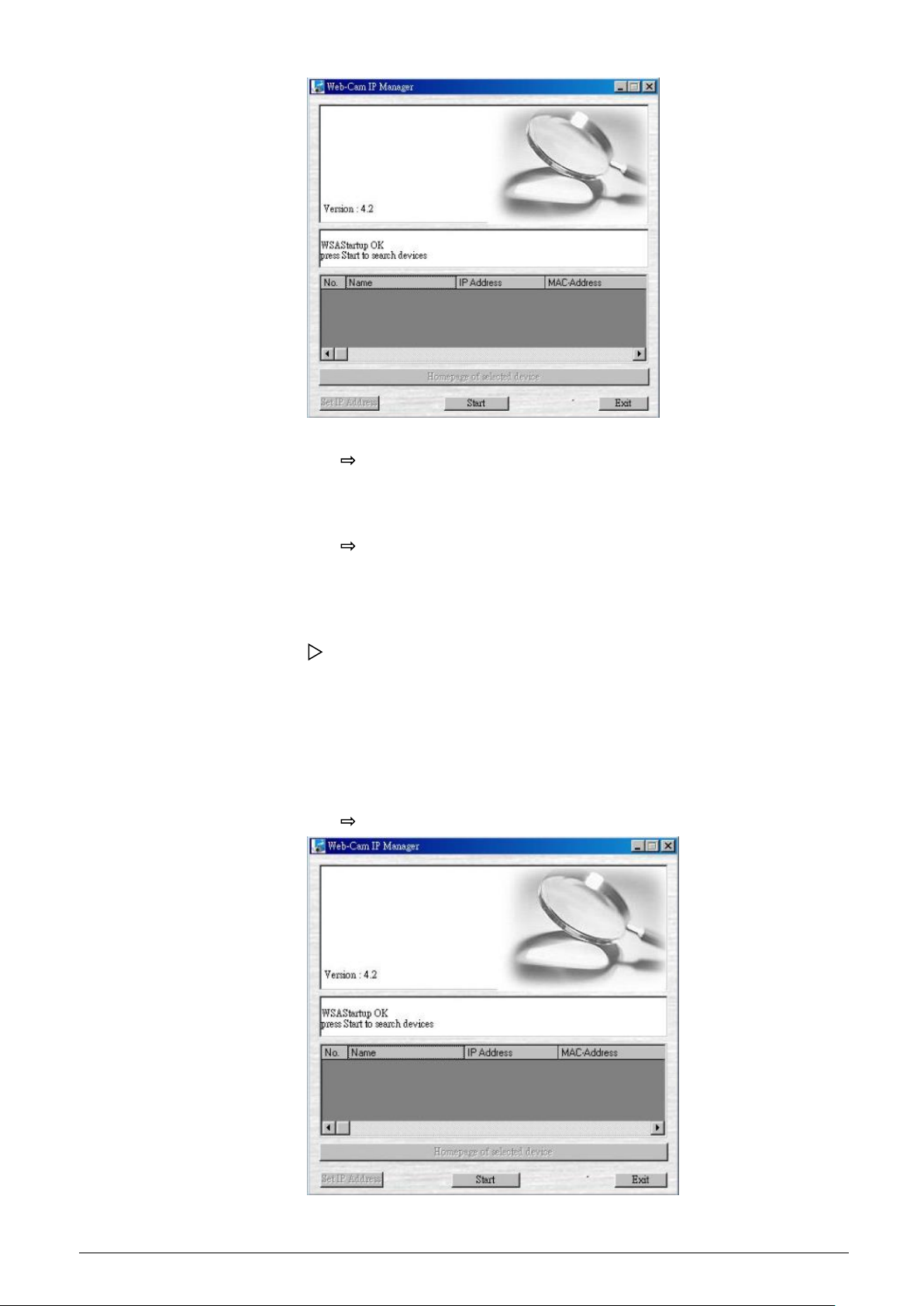
8.5 Using the camera search application "Webcam IP Manager"
The "Webcam IP Manager" is an application for searching for network cameras
that can currently be viewed from the administrator's personal computer or a
user's personal computer.
Setting up "Webcam IP Manager"
1. Insert the CD in the CD-ROM drive of the personal computer.
2. Double-click the "ipfinder.Setup" file in the CD-ROM and install
"Webcam IP Manager" in accordance with the instructions on the screen.
IMPORTANT
"Webcam IP Manager" is compatible only with Windows Vista, Windows XP
and Win7. Glitches may occur on your personal computer if it is run with another operating system. Do not install "Webcam IP Manager" with other operating systems.
Using "Webcam IP Manager" to search for a camera
Set the personal computer to "Administrator authorization" when using
"Webcam IP Manager".
1. Select "Start" > "Programs" > "Webcam IP-Finder".
Page 17
Installing the camera
© Vanderbilt 2016
17
2. Start "Webcam IP Manager" and click "Search".
All the cameras currently connected to the network will be displayed.
To exit the program, click "Exit".
3. Select the camera you want to log in to in the list of cameras and dou-
ble-click it.
The selected camera name and IP address are displayed in the net-
work camera login fields.
4. Log in to the selected camera as an administrator. (See "Login dialog")
To exit without logging in, click "Exit".
SSDP (Simple Service Discovery Protocol / network protocol)
Prerequisite:
The Web-Cam IP Manager and all devices are located in the same network
segment. If a device and the Web-Cam IP Manager are not located in the same
network segment, you must ensure that the associated gateway (router) passes the SSDP multicast messages sent by the Web-Cam IP Manager on to the
network segment where the device is located.
1. Start the Web-Cam IP Manager by loading IP Manager.exe. This appli-
cation is found on the CD included with delivery.
The Web-Cam IP Manager program window will open:
Page 18
Installing the camera
© Vanderbilt 2016
18
2. Click "Start".
The Web-Cam IP Manager program window will now display a list of all
the devices available for communication along with their IP and MAC
addresses. Each device's IP address or MAC address is unique.
3. Select the camera whose home page you want to access.
4. Click "Home page of selected device".
The home page of the selected camera will appear. See Section 6.8
Components of the unit home page.
8.6 Login dialog
The content of the following chapters is based on the assumption that Microsoft Internet Explorer IE 8.0 or higher has been installed.
A person who has logged in as an administrator can perform all functions.
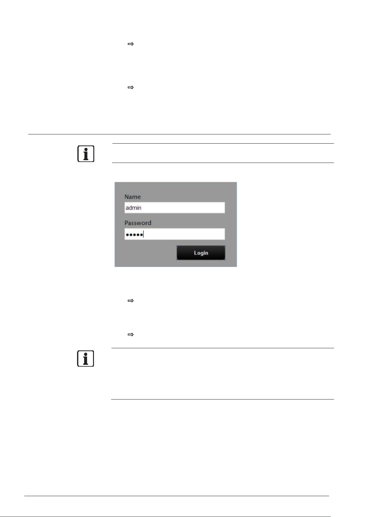
Administrator login
1. Search for the camera using the "Webcam IP-Finder", double-click the
camera you wish to log in to.
The login dialog will appear.
2. Enter the administrator login ID and password in the "Name" and
"Password" fields, respectively and click "Login". The administrator login
ID and password are "admin" and "admin" by default.
The camera image screen will appear.
IMPORTANT
The administrator login allows rewriting of all settings. Make sure to change the
de-fault administrator login ID and password to ensure camera security. Keep
the new administrator login ID and password handy for future use. Information
on how to change the administrator login ID and password can be found in
Section "Access protection.
Page 19

Installing the camera
© Vanderbilt 2016
19
8.7 Viewing and listening
Images of the network camera can be viewed using the Internet browser of
your personal computer.
Preparations before displaying
Enable cookies
Set "Browser setting when proxy server is used". Change "Security" in the
Internet options as follows.
1. Click "Tools" on Toolbar
2. Click "Internet Options"
3. Select the "Security" tab.
4. Click on "Intranet" if the camera to be operated is inside the intranet,
click on "Internet" if the camera is on the Internet.
5. Click "Level customize."
6. Activate the following radio buttons in the list displayed:
– "Enable" for "ActiveX control and plug in execute"
– "Enable" for "Execution of script of ActiveX control marked safe even
when script is executed"
– "Enable" for "Download of signed ActiveX control "
7. Click "OK."
8. Login to the camera.
Your browser will be launched and the camera login screen will appear.
See Section "Login dialog" for the login method.
When the security warning screen (VeriSign) appears on the first use of
the system, click "Yes."
Administrator authorization is needed to install "Active-X control." Install "Active-X control" after changing the personal computer setting to "Administrator
authorization."
Browser settings when proxy server is used
If a proxy server is used, setting the browser to bypass the proxy server during
communication with the network camera is recommended.
1. Launch the browser.
2. Click "Tools" on Toolbar
3. Select "Internet options".
4. Select the "Connect" tab.
5. Click "LAN Setting."
The screen for setting a local area network (LAN) will appear.
If the checkbox "Will use a proxy server" is not marked:
The browser is not set to use a proxy server. Click "Cancel" and quit
setting.
If the checkbox "Will use a proxy server" is marked:
1. Click "Detail setting."
A proxy setup screen will appear.
2. Enter the IP addresses of the network cameras in the fields marked
"Do not use the proxy server with addresses started with the following".
3. Click "OK."
When Windows XP SP2 is used: Click "Install" for "Active-X control."
Page 20
Installing the camera
© Vanderbilt 2016
20
All browsers except the IE can only be used for image viewing and compression setting.
A proxy server protected by a firewall sometimes cannot be connected to the
network camera. Consult the network administrator to avoid impacts on network camera operations.
Communication with the network cameras via a proxy server may cause problems. Install the network cameras after consulting with the network administrator.
If the network cameras are used in conjunction with a proxy server, it may take
some time for the images to be displayed after a login, or the frame rate of the
delivered images may be reduced.
All browsers except the IE only support image viewing and compression setting.
When using Windows XP SP2
If the camera image screen is not displayed, proceed as follows.
1. Select "Pop-up Blocker" on the toolbar.
2. Select "Always Allow Pop-ups from This Site..."
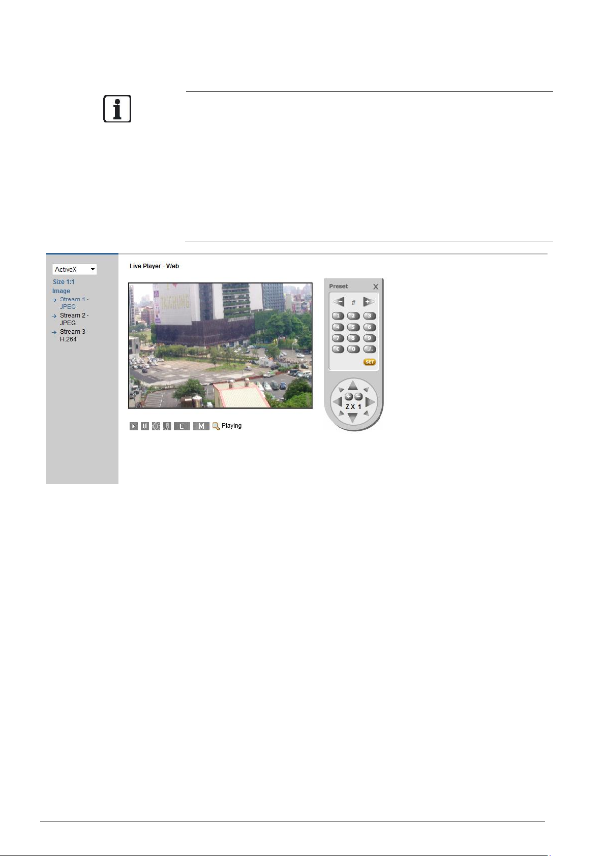
Components of unit home page
OSD: displays camera name, date and time.
Play: shows the live image
Pause: pauses the live image
Speaker: On/Off
Microphone: On/Off
Language: standard setting is English. The website supports 5 different lan-
guages. Image streams 1, 2 & 3: Triple streams 1, 2 & 3 are available for selection. H.264 & JPEG only support 2 streams when the resolution sets at QXGA
and 1080P.
E-zoom: PTZ control, preset settings and more.
Page 21
Installing the camera
© Vanderbilt 2016
21
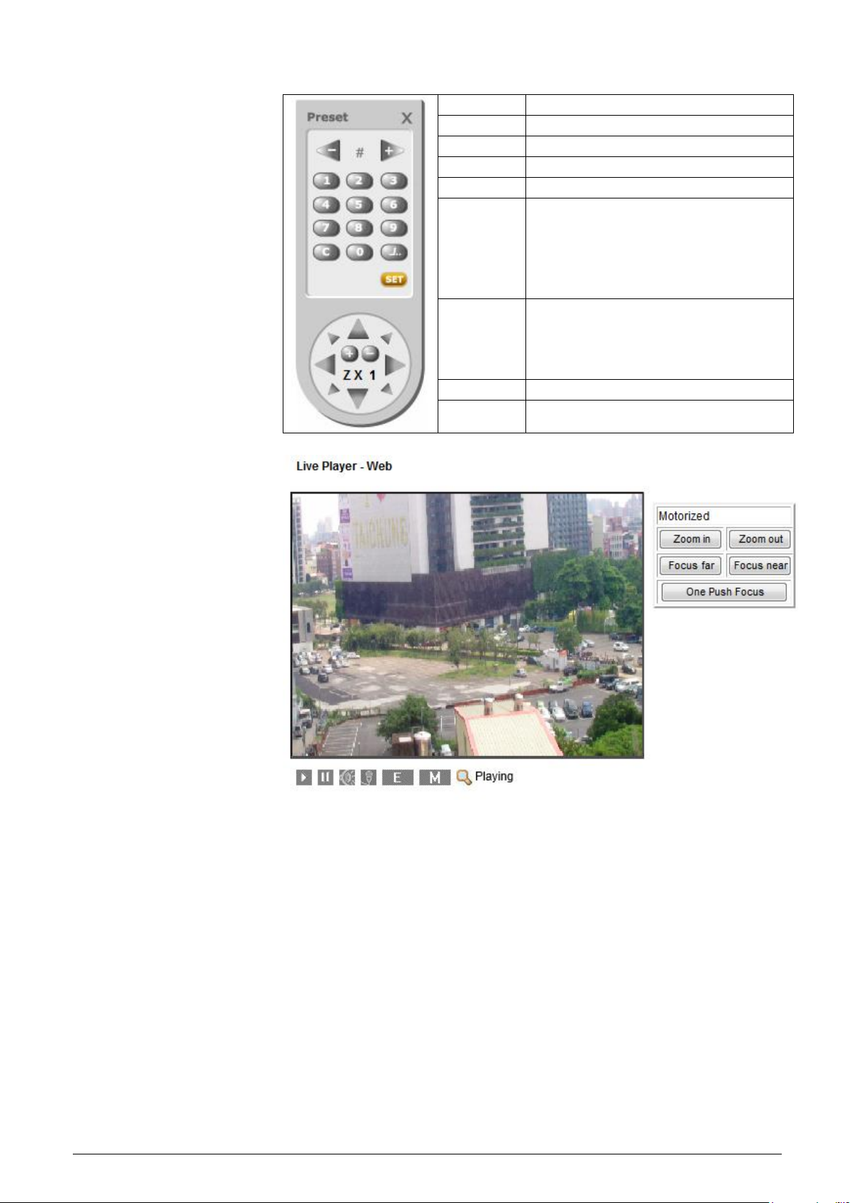
Ezoom control panel
X
Exit the remote control
- / +
Previous / next preset position
0-9
Select a preset position (1-64)
./..
Toggle between 1 and 2 digits
C
Clear
SET
Save current position. (Click SET and then
click the number for the preset position to
be saved.
Up to 64 positions can be stored for the
network camera.)
Arrow keys
Use the arrow keys to move the pan/tilt
position.
(NOTE: Pan/tilt position control is only
available if zoom is larger than 1)
+ / -
Zoom in / out
ο/ ∞
Focus near / far
Motorized panel
Zoom in/out: Users can click zoom in /out the lens in order to obtain a close-up
or a wide view.
Focus far/near: User can manually click Focus Near/Focus Far to adjust the fo-
cus for optimal picture clearness.
One push focus: Click “One push focus” to have the lens focus automatically
once.
Page 22

Installing the camera
© Vanderbilt 2016
22
Page 23
Installing the camera
© Vanderbilt 2016
23
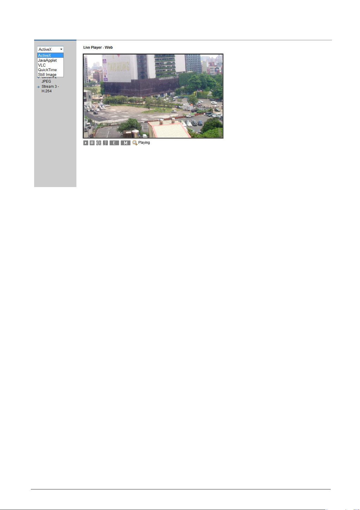
Live view player
ActiveX: Please use IE 8.0, IE 9.0 and IE 10.0 browser to view image.
JavaApplet: Please use Firefox browser to view image.
VLC: Before view the image, please install VLC player in PC.
QuickTime: Before view the image, please install VLC player in PC.
Still Image: Shows an image.
Page 24

Installing the camera
© Vanderbilt 2016
24
8.8 Resolution
There are different kinds of resolution depending on the function selected for
the network camera.
Codec
Triple stream
Primary
Secondary
Tertiary
H.264/JPEG
QXGA@12fps
VGA/CIF/QVGA/Cropping
@12fps
NA
1080P@25fps
VGA/CIF/QVGA/Cropping
@25fps
NA
720P/480P/VGA/CIF/QVGA
@25fps
720P/480P/VGA/CIF/QVGA
@25fps
480P/VGA/CIF/QVGA/Cropping
@25fps
480P/VGA/CIF/QVGA
@25fps
480P/VGA/CIF/QVGA
@25fps
480P/VGA/CIF/QVGA/Cropping
@25fps
Codec
Ezoom
OSD
Cropping
Mask Zone
Frame Rate
Stream 1 QXGA
H.264
JPEG
O
O X O
12
Stream 2 VGA
H.264
JPEG
O
O
O
(It can switch to cropping
size)
O
12
Stream 1 1080P
H.264
JPEG
O
O X O
12
Stream 2 VGA
H.264
JPEG
O
O
O
(It can switch to cropping
size)
O
12
Stream 1 720P
H.264
JPEG
O
O X O
25
Stream 2 720P
H.264
JPEG
O
O X O
25
Stream 3 480P
H.264
JPEG
O
O
O
(It can switch to cropping
size)
O
25
Stream 1 480P
H.264
JPEG
O
O X O
25
Stream 2 480P
H.264
JPEG
O
O X O
25
Stream 3 480P
H.264
JPEG
O
O
O
(It can switch to cropping
size)
O
25
Stream 1
QVGA/CIF
H.264
JPEG
O
O X O
25
Stream 2
QVGA/CIF
H.264
JPEG
O
O X O
25
Stream 3
QVGA/CIF
H.264
JPEG
O
O O (It can switch to cropping
size)
O
25
Page 25
Configuration
© Vanderbilt 2016
25
9 Configuration
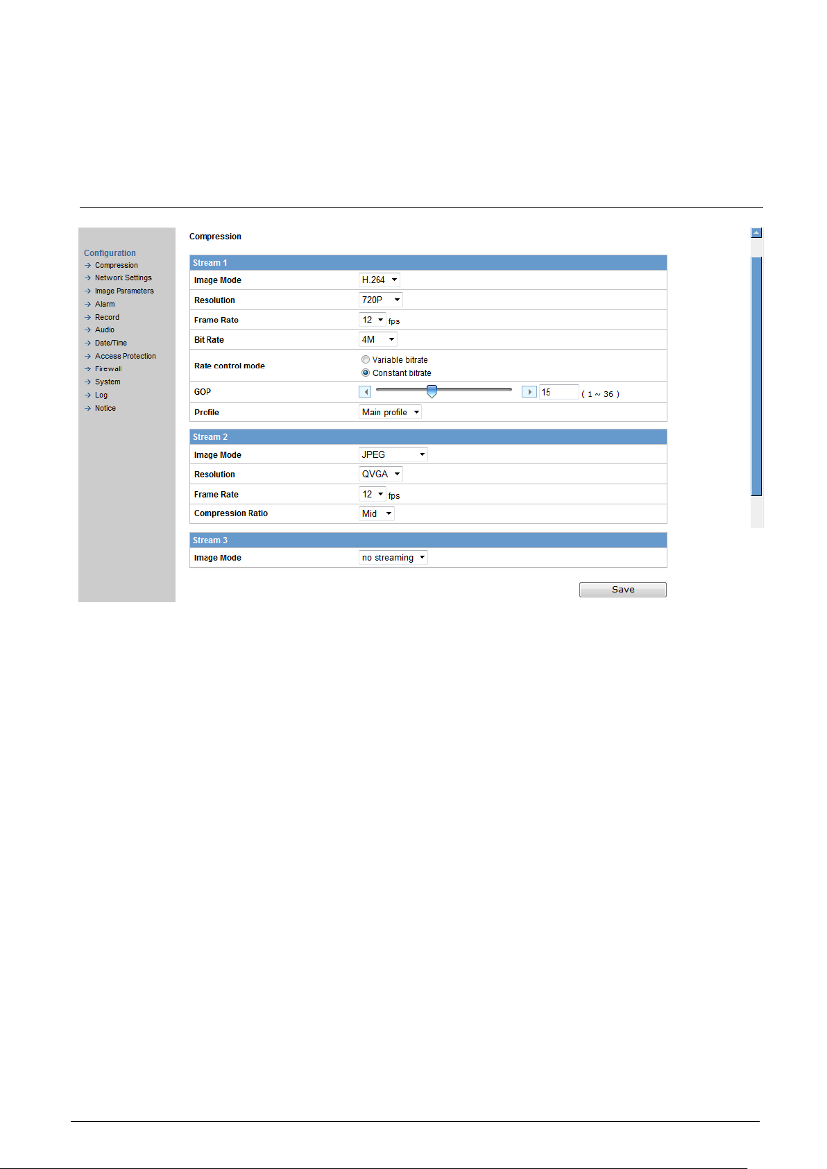
9.1 Compression
Image mode
3 streams can be selected. Stream 1, stream 2 and stream 3 can be
set to H.264, JPEG
All resolutions H.264, JPEG are possible.
H.264- The following settings are enabled when "Image Mode" is set to H.264
Resolution
Configure the resolution. The higher the resolution the larger the image
files. Possible settings: QXGA, 1080P, 720P, 480P, VGA, CIF, QVGA.
Frame rate: 7 frame rates can be selected (1, 2, 3, 5, 10, 12, 25)
Bit Rate: It’s optional only when constant bit rate is chosen. Select the
desired bit rate including 512K, 1M, 2M, 4M, 6M and 8M kb/s.
Rate control mode: you can choose between variable bit rate and con-
stant bit rate.
Bit Rate Max & Min: It’s optional only when variable bit rate is chosen.
The bit rate range is from 512K ~ 8M.
GOP: default is 25 (1 I frame plus 24 P frames). GOP can be selected
between 1 and 64. (max GOP=Framerate*3, max=64)
JPEG - The following settings are enabled when "Image Mode" is set to
"JPEG".
Resolution
Configure the resolution. The higher the resolution the larger the images
file. Possible settings: QXGA, 1080P, 720P, 480P, VGA, CIF, QVGA
Frame Rate: 7 frame rates can be selected (1, 2, 3, 5, 10, 12, 25)
Compression ratio
Set the quality of the delivered images. The size of the image files (JPEG
files) depends on the compression ratio.
– Low compression: This setting produces the highest image quality. The
file size increases.
– Mid compression: Standard setting.
Page 26

Configuration
© Vanderbilt 2016
26
– High compression: This setting produces the lowest image quality. The
file size decreases.
9.2 Network settings
You can configure your basic camera settings, DDNS, FTP server, RTSP,
HTTPS, IEEE802.1X, SNMP & 3GPP by selecting "network setting" in the
"Configuration" menu.
9.2.1 Basic
BASIC
Camera Name: Enter the name of your camera here. The default name is
"nwcam05". Camera Name Enable: Select "ON" to enable this function or
"OFF" to disable it.
NETWORK Mode:
DHCP: The IP address is obtained automatically;
PPPoE: The IP address is obtained automatically;
Manual: Enter the IP address as shown in the screenshot above.
IP Address: If you have selected the option "Manual", enter your IP address
here. Subnet Mask: Please use default number: 255.255.255.0.
Default Gateway: Leave blank. It is not necessary to enter a Default Gateway if
it is not used. Ask your Network Administrator for information on the default
gateway.
Primary DNS: (same as above)
Secondary DNS: (same as above)
Ipv6 address configuration
Ipv6: Select "ON" to use the new internet protocol or "OFF" to disable it.
Page 27

Configuration
© Vanderbilt 2016
27
Port
Stream 1 to Stream 3:
We recommend using the default settings. In case these need to be changed,
contact your system administrator.
UPnP Use
When "ON" is selected, the camera can be detected automatically by the PC. It
is not necessary to have the Web cam IP manager installed.
Bonjour Use
When "ON" is selected, the camera can be detected automatically by the Inter-
net Explorer browser. It is not necessary to have the Web cam IP manager installed.
AUDIO output Use
When "ON" is selected, a voice message indicating camera’s IP address can
be delivered to a headphone.
Page 28

Configuration
© Vanderbilt 2016
28
9.2.2 DDNS Settings
This function is available when you have registered with a DDNS
provider. Select "ON" to enable the DDNS function.
1. Select your DDNS server from the list box, enter your user ID and
password and confirm your password.
2. Click "Save" to save your settings.
9.2.3 FTP Server
1. Select "ON" to activate the FTP function. Enter your login ID and pass-
word and confirm your password.
2. Select the number of maximum connections from the "Max Simultane-
ous Connections" list box. Click "Save" to save your settings.
This function is used to download directories/files to or to delete them from the
SD memory card.
Page 29

Configuration
© Vanderbilt 2016
29
9.2.4 RTSP
Authentication: Select "ON" to enable the RTSP function. Enter your login ID
and password and confirm your password.
Stream1-3: Select the transfer type and enter the RTSP port, video port, audio
port and meta port.
9.2.5 HTTPS
Here you can upload the *. pem file of certificate or *.pem file of private key.
Click "Browse". A window will pop up. Select the file you want to upload. Click
upload to upload the file.
Page 30

Configuration
© Vanderbilt 2016
30
9.2.6 IEEE802.1X
Certificate:
1. Click "Browse"
A window will open.
2. Select the desired certificate
3. Click "Upload" to upload the *.pem file of certificate.
Setting:
EAPOL version: Select 1 or 2.
EAP identity: Enter the EAP identity.
Private key password: Enter your private key password.
Enable IEEE 802.1X: Select "ON" to enable it or "OFF" to disable it.
Page 31

Configuration
© Vanderbilt 2016
31
9.2.7 SNMP
Select "ON" to enable SNMP V1, SNMP V2C and SNMP V3, respectively, or
select "OFF" to disable them.
9.2.8 3GPP
3GPP is the third generation technical standard which refers to GSM core network as the basis and UTRA as the wireless interface.
Page 32
Configuration
© Vanderbilt 2016
32
9.3 Image parameter
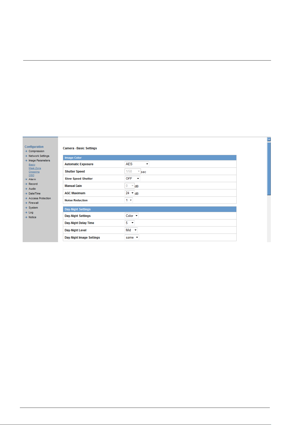
9.3.1 Basic camera settings
Here you can configure the basic settings of the camera such as image size
and quality.
1. Select "Image Parameters" in the "Configuration" menu.
– A sub menu for camera function setting will appear.
2. Select "Basic" in the sub menu.
– The "Camera - Basic Settings" dialog will appear.
3. Configure the individual settings.
– Click "Save" to save your settings.
The settings will not be applied unless "Save" is clicked.
Page 33

Configuration
© Vanderbilt 2016
33
Automatic Exposure:
Controls the light intensity of the image. 4 types of specific application
conditions can be selected: Manual, AES(Automatic Electronic Shutter),
ALC(Auto Lens Control), and LightBooster by the camera depending on
your application environment. When use the Manual, the Shutter speed is
enabled to adjust.
When use the Lightbooster, the user can see color image in very dark environment. However, the Day-Night setting always sets on color mode.
Shutter Speed:
Set the desired shutter speed between 1/25 and 1/8912s. The shutter
speed can be set to 1/25, 1/50, 1/100, 1/120, 1/1024, 1/2048, 1/4096, or
1/8192s. The network camera will adjust the aperture to the ambient light
level. (ALC)
Page 34

Configuration
© Vanderbilt 2016
34
Slow Speed Shutter:
Slow Shutter can be enabled if the sensitivity is still not good enough under "High" gain condition at dark. Optimal image level can be maintained
by appropriate gain and shutter combination that determined automatically
inside the unit system. Slow Shutter can be selected from OFF, 1/25,
1/12.5, and 1/6.25. As slow shutter activates, the exposure time becomes
longer and frame rate becomes smaller, and moving objects may result in
blurred images.
Manual Gain:
Adjust the manual gain level between 0 and 36 dB. This function is available for manual lenses only.
AGC Maximum:
Set max gain. You can set 24 or 36dB.
Noise Reduction:
Users can configure the noise reduction related setting 1~6 to reduce
noise on the screen. Selecting 6 provides the best image without noise.
Day-Night Settings:
Select "Auto", "Color" or "BW" mode according to the environment. Only
active if not linked to alarm input.
Day-Night Delay Time:
Choose the day-night delay time from 0, 5, 10, 15, 30.
Day-Night Level:
Choose the day/night level: Low, Mid, High.
Day-Night Image Setting:
Select either "same" or "differ" mode based on Day-Night settings at Auto
mode. When chosen "same" mode, it means Day & Night image settings
will refer to "image color 1". Oppositely, when chosen "differ" mode, it
means Day image settings will refer to "image color 1" and Night image
settings will refer to "image color 2".
Preset image:
Choose "OFF", "Indoor", "Outdoor", "Tunnel" and "Casino", according to
the environment.
Brightness adjustment:
Adjust the brightness between -255 and 255.
Contrast:
Set the contrast level between 0 and 128.
Saturation:
Adjust the saturation between 0 and 255.
Hue:
Set picture hue from level -15~15. Selecting 15 provides the deep hue.
AWB
Set the white balance values to meet the environment condition for best
color rendition.
ON: the color of camera is automatically adjusted according to external
lighting condition.
OFF: adjustable by user manually, this is useful for some specific condition
which AWB may be unaffordable to perform correctly. You can set the current R/B color temperature manually.
Indoor: default for 10000K condition.
Outdoor: default for 6500K condition.
R Gain, G Gain, B Gain :
Adjust manual gain value of R Gain, G Gain, and B Gain between 0 and
255. This function is available for manual lenses only.
Page 35

Configuration
© Vanderbilt 2016
35
Sharpness:
Increasing the sharpness value enhances the edges and small features in
your camera images. You can adjust the sharpness between 1 and 15.
Back Light Compensation(BLC):
Set an area for backlight compensation. If backlight compensation is activated, the camera performs the exposure control only within the specified
area. Backlight compensation is a function that adjusts the brightness of a
selected area to an optimum level. This function is necessary when an auto iris lens tends to close due to an intense light coming from the back of
the object in the area to be viewed so that areas become dark and visibility
deteriorates.
WDR:
Set this option to "ON" or to "OFF". It is intended to provide clear images
even under backlight circumstances where intensity of illumination can
vary excessively namely where there are both very bright and very dark
areas simultaneously in the field of view. WDR enables the capture and
display of both bright and dark areas in the same frame, in a way that
there are details in both areas, i.e. bright areas are not saturated, and dark
areas are not too dark.
Picture Flip:
When mounted upside down select ON to activate the flip function. With
this function you can flip an image upside down. Select "ON" to activate or
"OFF" to deactivate the flip function.
Picture Mirror:
The selected image will be side-inverted. Select "ON" to activate or "OFF"
to deactivate the mirror function.
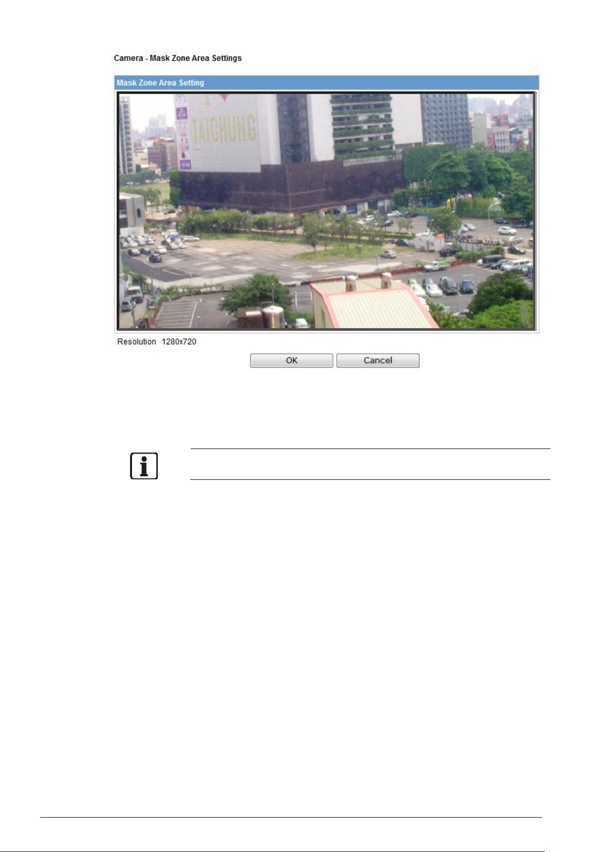
9.3.2 Camera mask zone settings
Page 36
Configuration
© Vanderbilt 2016
36
Select "ON", then click "Set Mask Zone" to start mask setting.
Drag a mask rectangle on the screen. Click "OK" to complete the selec-
tion.
Click "Save" to enable the mask setting.
Up to 4 masks can be set on the screen.
Page 37
Configuration
© Vanderbilt 2016
37
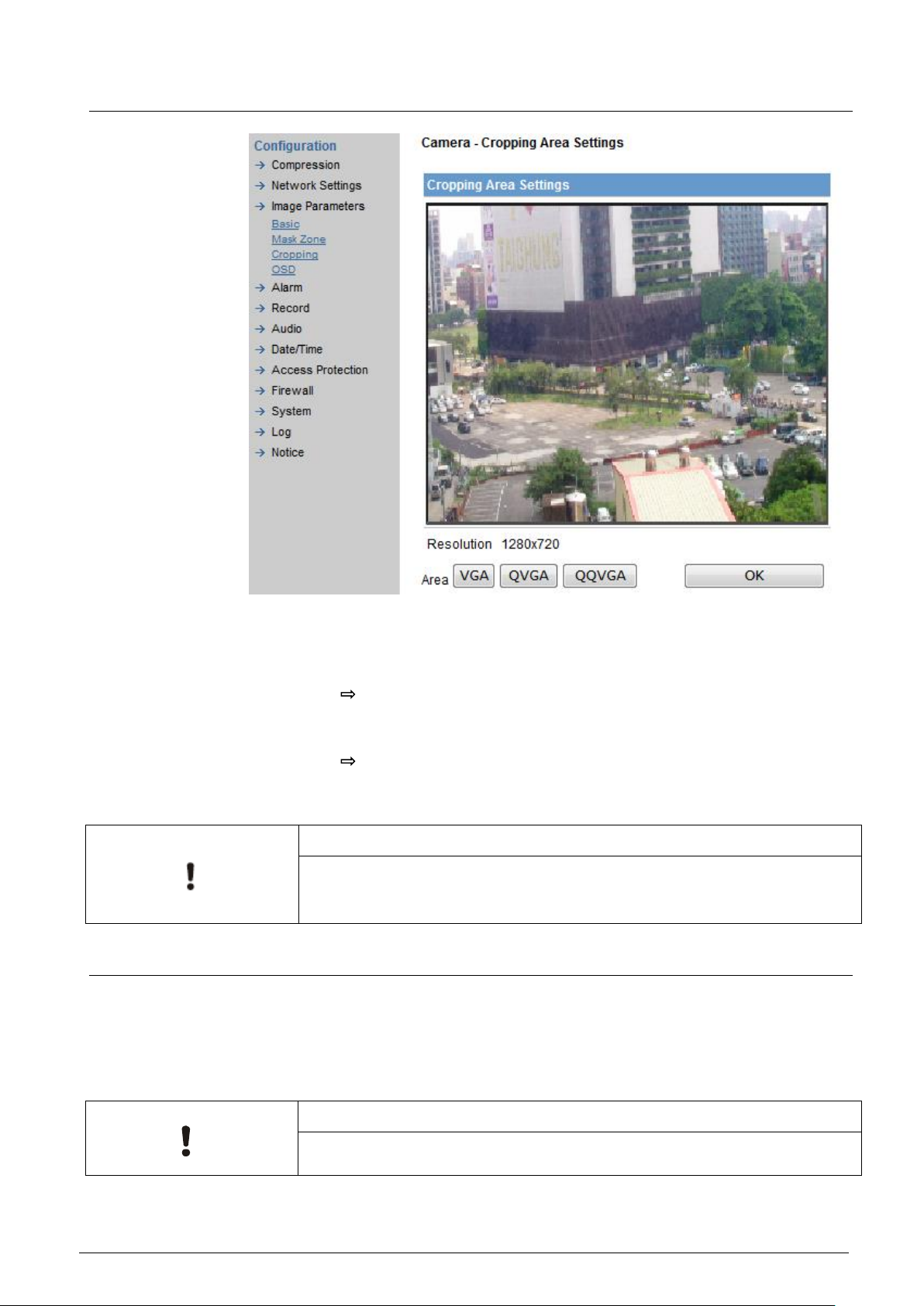
9.3.3 Camera cropping settings
1. A cropping setting screen will pop up as shown. Select one of the
cropping options (VGA, QVGA, and QQVGA) at the bottom of the screen.
A red-mesh rectangle will appear on the screen.
2. Select one of the predefined sizes.
The zone appears at the screen.
3. Move the zone by clicking the left mouse button in the center of the
target position.
The red mesh will jump to that position.
4. Click "OK" to save and finish the settings.
5. Click "Save" to save your settings.
NOTICE
1. Cropping is not supported when the stream1 size is CIF or QVGA!!
2. The largest cropping size is VGA and the smallest cropping size will be
QQVGA.
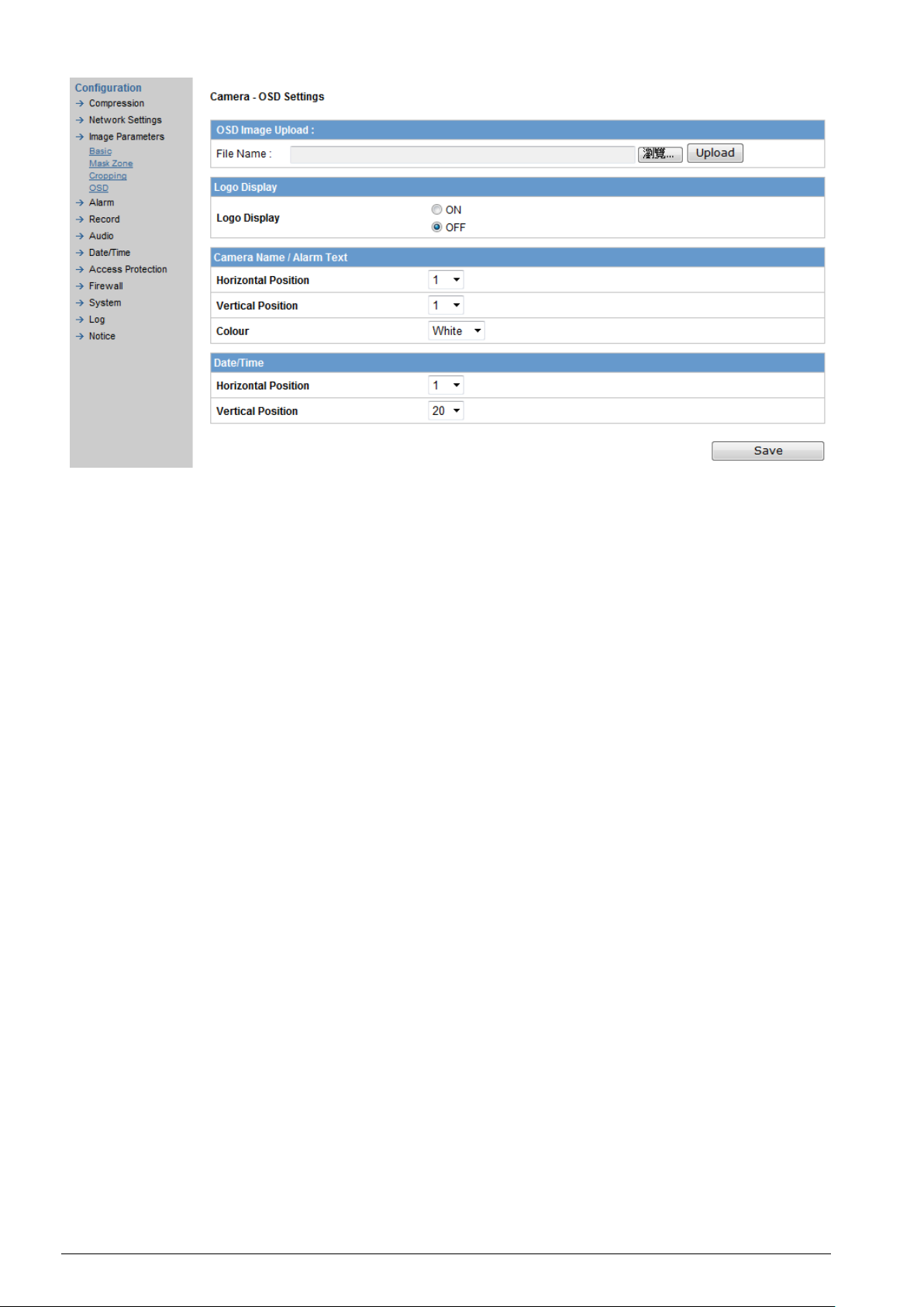
9.3.4 Camera OSD settings
This function can upload a new OSD image, displays logo image as Vanderbiltlogo, and setups the text position and color of camera name, alarm text or
DATE/TIME on the screen. Of course, the corresponding ENABLE flag for each
item shall be "ON" to activate this function, such as camera name Enable in
Network setup, Text enable in Alarm setting and Display in DATE/TIME setting.
NOTICE
The OSD image accepts a *.bmp file and the BMP file size have to be below
70K (70x1024).
Page 38
Configuration
© Vanderbilt 2016
38
Page 39
Configuration
© Vanderbilt 2016
39
9.4 Alarm
9.4.1 Alarm
If a sensor or another device is connected to the alarm input, an alarm will be
triggered when an event is detected by the sensor or the other device. For example, if a sensor is attached to a door, an alarm will be triggered each time
the door is opened. An enabled motion sensor will trigger an alarm a change
on a screen is detected.
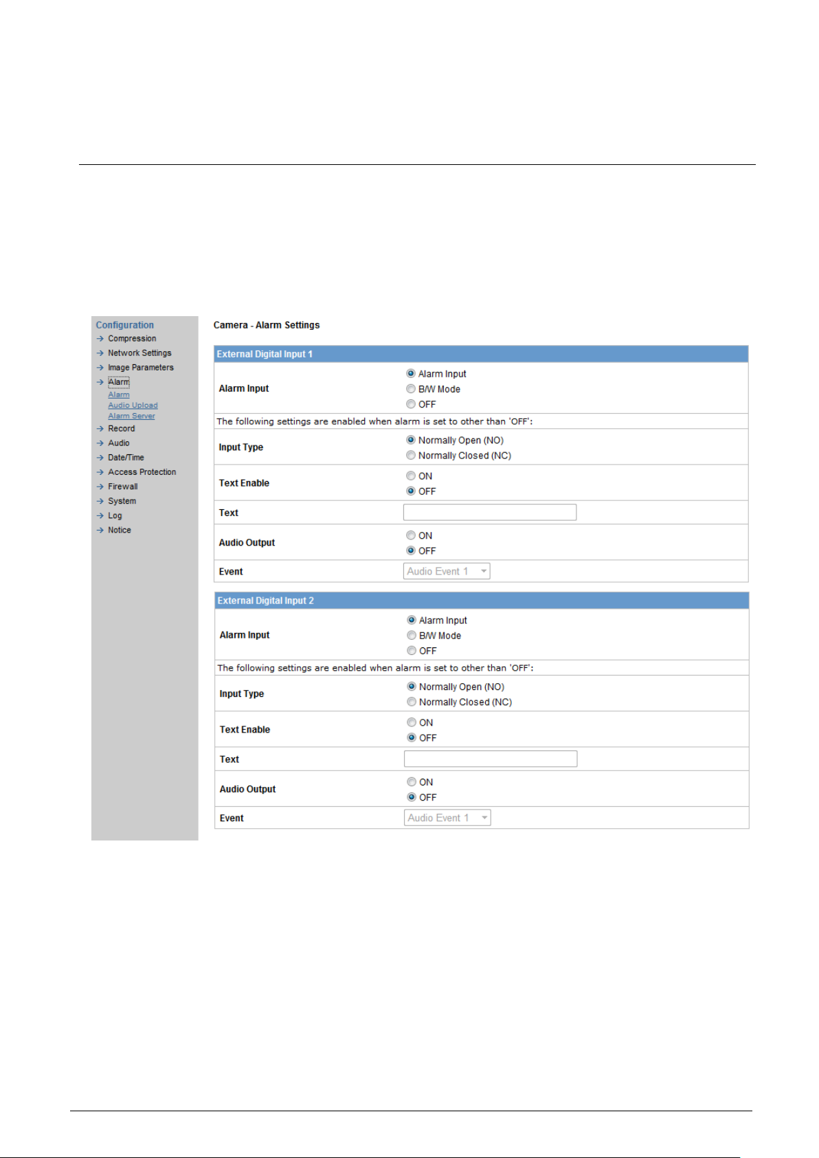
On the rear panel, there are 3 digital alarm inputs (AL1, AL2, and AL3). Before
using the alarm function, you need to define some parameters.
External digital input 1, 2
1. Alarm Input
When "Alarm Input" is selected: external alarm will be detected.
The following functions will be enabled when the option "Alarm Input" is
selected. B/W Mode: The camera is switched to monochrome mode when
a trigger signal is received.
2. Input Type
Normally Open (NO): open if nothing occurs but closed in case of an
alarm. Normally Closed (NC): closed if nothing occurs but open in case of
an alarm.
3. Text Enable
When "ON" is selected, an alarm message will be displayed on the screen.
Page 40
Configuration
© Vanderbilt 2016
40
4. Text
Enter a text for the alarm message.
Max. 22 characters can be entered.
5. Audio Output
When "ON" is selected, an audio alarm message will be sent to an exter-
nal speaker.
A speaker with integrated amplifier inside has to be connected to the AUDIO
out jack.
6. Event
Select an event.
Pre-recorded voice files with the extension .wav that have been uploaded
to the SD memory card can be selected as alarm messages. Up to 10 audio sources can be selected.
External digital inputs 3
External digital inputs 3: All configurations are the same as those made for "ex-
ternal digital input 1, 2", except that input mode B/W is not available.
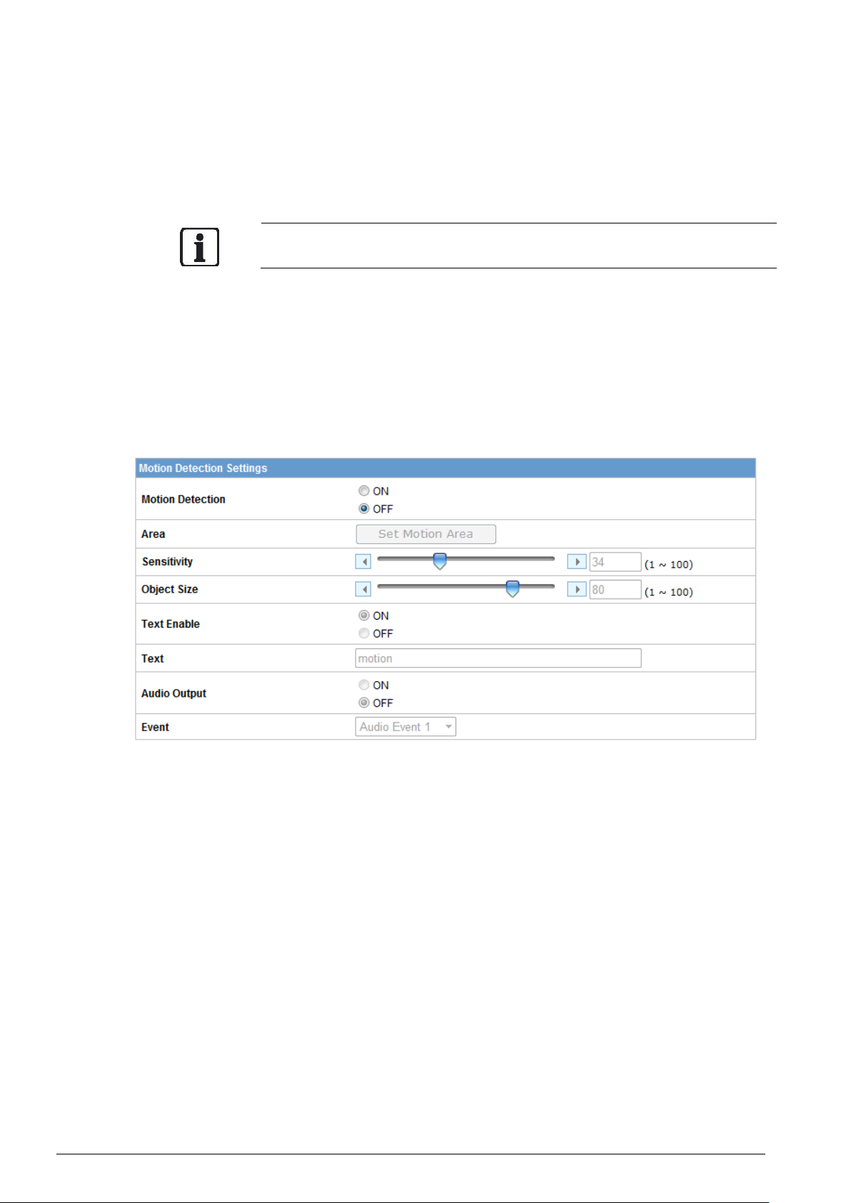
Motion detection settings
The settings are similar to those for alarm inputs, with some additional func-
tions:
1. Motion Detection
Select "ON" to enable the motion detection function. Default setting: "OFF".
2. Area
Click "Set Motion Area". An image screen will pop up. Select the target ar-
ea by dragging the mouse.
3. Sensitivity
Choose different levels of 1~100 for sensitivity.
"1": Motion is activated with slight changes in brightness or motion.
"100": Motion is activated with big changes in brightness or motion.
4. Object Size
Choose different levels of 1~100 for object size. Set the percentage area
size for a recognizable object.
"100%": Very large objects trigger motion.
"30%": Small objects trigger motion.
5. Text Enable
When "ON" is selected, an alarm message will be displayed on the screen.
Page 41
Configuration
© Vanderbilt 2016
41
6. Text
Enter a text for a motion message.
Max. 22 characters can be entered.
7. Audio Output
When "ON" is selected, an audio alarm message will be sent to an external speaker.
A speaker with integrated amplifier inside has to be connected to the AUDIO
out jack.
8. Event
Select an event. Pre-recorded voice files with the extension .wav that have
been uploaded to the SD memory card can be selected as alarm messages. Up to 10 audio sources can be selected.
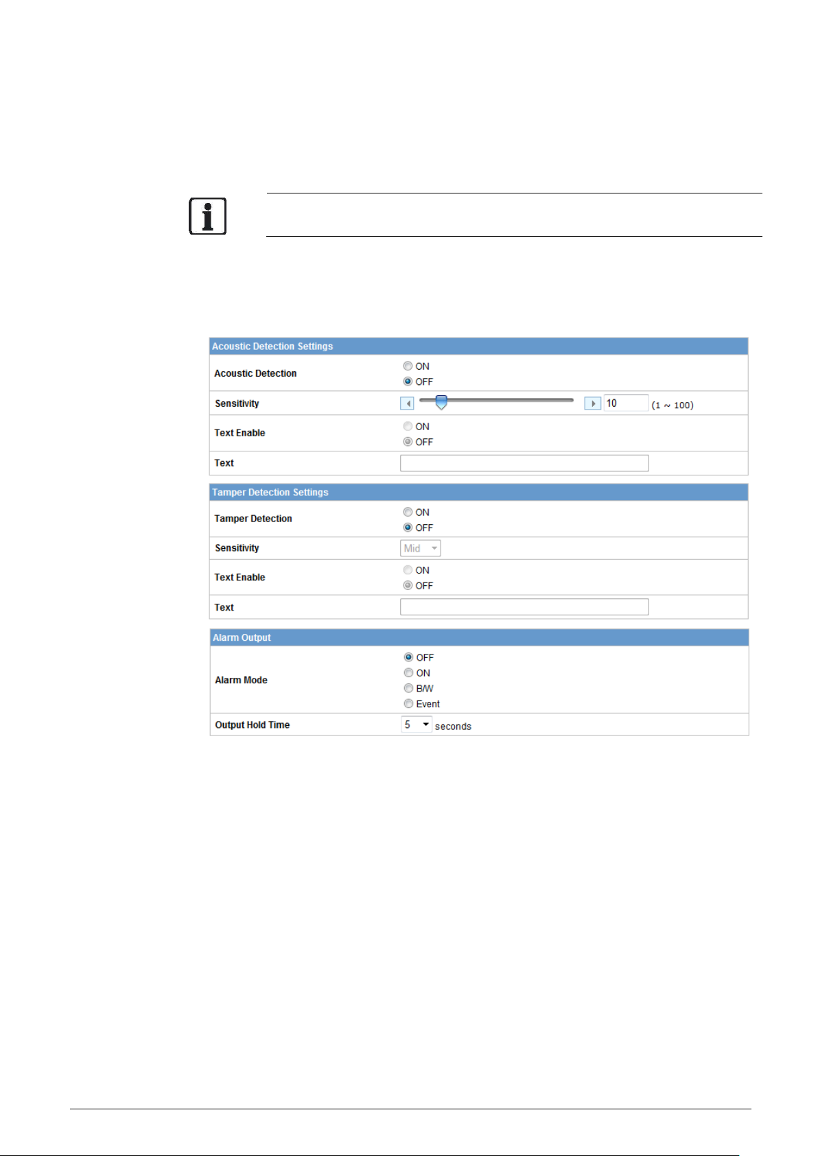
Acoustic detection settings
1. Acoustic detection
This function indicates a voice event detected. When turned on and triggered, the alarm message will be recorded to SD card.
2. Sensitivity
Choose different levels of 1~100 for sensitivity. "100": Voice is activated
with low volume. "1": Voice is activated with loud volume.
Tamper detection settings
1. Tamper detection
This function indicates a tampering event detected such as a manual
change in the camera's direction, removal of the camera lens, defocusing
of camera, intentionally covered with cloth or spray-painted of the camera
lens. When turned on and triggered, the alarm message will be recorded
to SD card.
2. Sensitivity
Select the desired sensitivity.
High: Even small changes are detected.
Mid: Intermediate between High and Low.
Page 42

Configuration
© Vanderbilt 2016
42
Low: Only large changes are detected.
Page 43

Configuration
© Vanderbilt 2016
43
NOTICE
Acoustic detection and destroy detection must insert SD card. With no SD card
insert, the two detection functions are unavailable and cannot be selected in the
conditions of FTP Recording, E-mail Recording and NAS Recording.
Alarm output
1. Alarm mode:
The alarm output can be activated when any of the following events occurs:
– B/W: when the image changes to monochrome.
– Event: When alarm input 1, alarm input 2 or alarm input 3 or motion is
triggered, the alarm output will reflect this immediately as well.
2. Output hold time:
Set a time to hold the alarm output. You can select 0, 5, 10, 15, or 30 seconds. This function is used when a siren, buzzer or emergency light is
connected.
9.4.2 Audio event upload
Select an audio event. Upload the *.wav file as a voice alarm message to the
SD card or a PC. Up to 10 audio events can be selected. Alarm input 1 and
motion setting will show different effects depending on which audio event you
selected.
NOTICE
The audio event only accepts *.wav file and the audio time have to be in 5 secs.
Page 44

Configuration
© Vanderbilt 2016
44
Click browse, enter the destination folder and specify the *.wav file you want to
upload. Before Uploading, please make sure that the SD memory card has
been inserted in the camera. Otherwise the upload action fail and a web will
pop up with saying SD card not ready.
Once upload files successfully, you can open the alarm settings page and select different audio voice as alarm messages in event drop-down menu.
9.4.3 Alarm server
Configure the alarm server as follows:
Page 45

Configuration
© Vanderbilt 2016
45
1. Conditions:
Select either "Alarm" or "Motion".
2. Alarm Server IP Address:
Enter the IP address of the alarm server.
3. Alarm Server Port Number:
Enter the alarm server port number.
4. Alarm Input Message:
Enter a message text. This text must not be longer than 64 characters.
When an alarm event occurs, the alarm server will receive this message
text.
5. Motion Alarm Message:
Enter a message text. This text must not be longer than 64 characters.
When a motion event occurs, the alarm server will receive this message
text.
Page 46

Configuration
© Vanderbilt 2016
46
9.5 Record
9.5.1 Basic
Recording by alarm/motion
Prerequisite: The alarm inputs and motion detection have been config-
ured.
Then proceed as follows:
1. Record Source
Select either JPEG or H.264 format
2. Pre-Recording Frame
Select the number of images to be recorded before an alarm and motion
occurs. Images of the moment when the alarm and motion occurs are not
included.
With JPEG format, 0, 1, 3, 5, or 10 frames can be selected.
Not required with H.264 format.
3. Pre-Recording Cycle
Set a time interval for pre-alarm and pre-motion recording. With JPEG
format, 1, 2, 5, 10, 30s can be selected.
Not required with H.264 format.
4. Recording Frame
Select the number of images to be recorded immediately after an alarm
and motion has occurred. Images of the moment when an alarm and motion occurs are not included.
With JPEG format, 1, 2, 5, 10, 30, or 60 frames can be selected.
Not required with H.264 format.
5. Recording Cycle Set a time interval for alarm recording. With JPEG
format, 1, 2, 5, 10, 30,60,90,120s can be selected.
Not required with H.264 format.
6. Recording Time
When H.264 is selected, the recording time can be set to 2, 5, or 10s.
NOTICE
When selected H.264 source, the schedule recording of FTP will be disabled.
Page 47

Configuration
© Vanderbilt 2016
47
9.5.2 FTP Recording Basic
You can save image files via FTP. Set the FTP recording conditions first.
Choose FTP server1.
FTP Recording Conditions
You can save your image files generated by scheduled recording, alarm
recording, motion triggered recording, acoustic recording, or tamper recording.
Scheduled Recording
Select the recording condition in the recording schedule table for all days
from Monday to Sunday: Stop, All Day, Schedule 1 or Schedule 2.
Page 48
Configuration
© Vanderbilt 2016
48
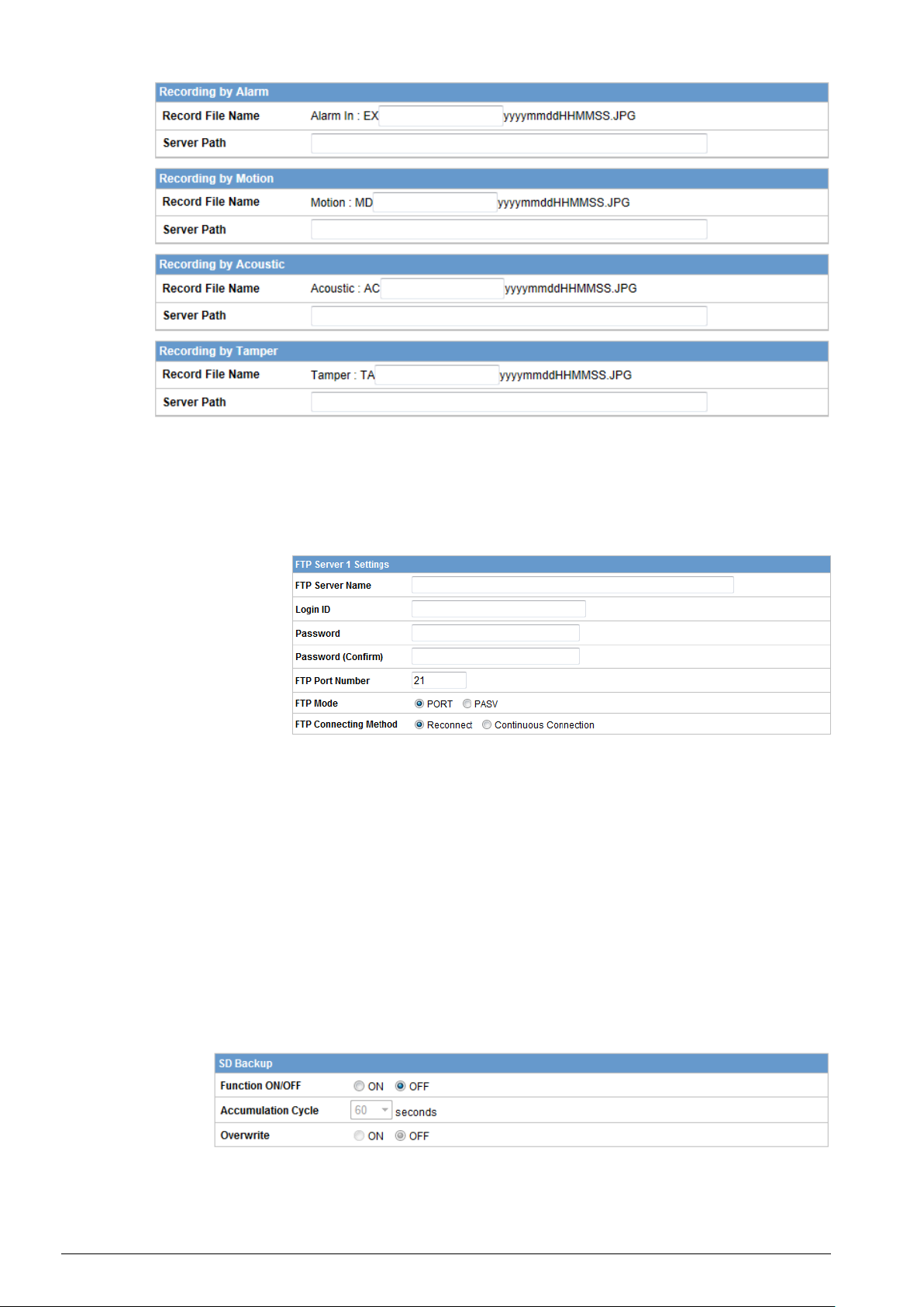
Alarm recording, motion triggered recording, acoustic recording and
tamper recording
Record File name: Set a file name.
Server Path: Set the data path where the data is to be stored on the serv-
er.
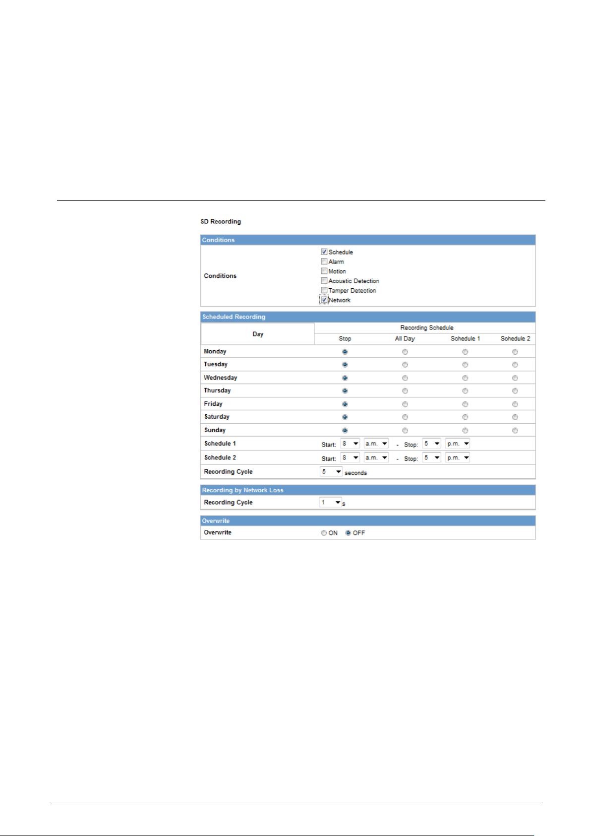
FTP Server Settings - Server 1
Enter the FTP server name, Login ID, Password, FTP port number, FTP mode,
and FTP connecting method.
FTP Server Name: Enter a server name or address.
Login ID: Only for users who are authorized to access the server.
Password: Enter the registered password associated with the login ID.
Password (Confirm): Re-enter the password
FTP Port Number: Set “21” as default
FTP Mode: PORT - This mode is for most FTP applications; PASV -
This mode is used when the camera is operated in a network environment
that is behind a firewall.
FTP Connecting Method: Reconnect - The network camera logs in/out
for each file transfer; Continuous Connection - The network camera is always connected.
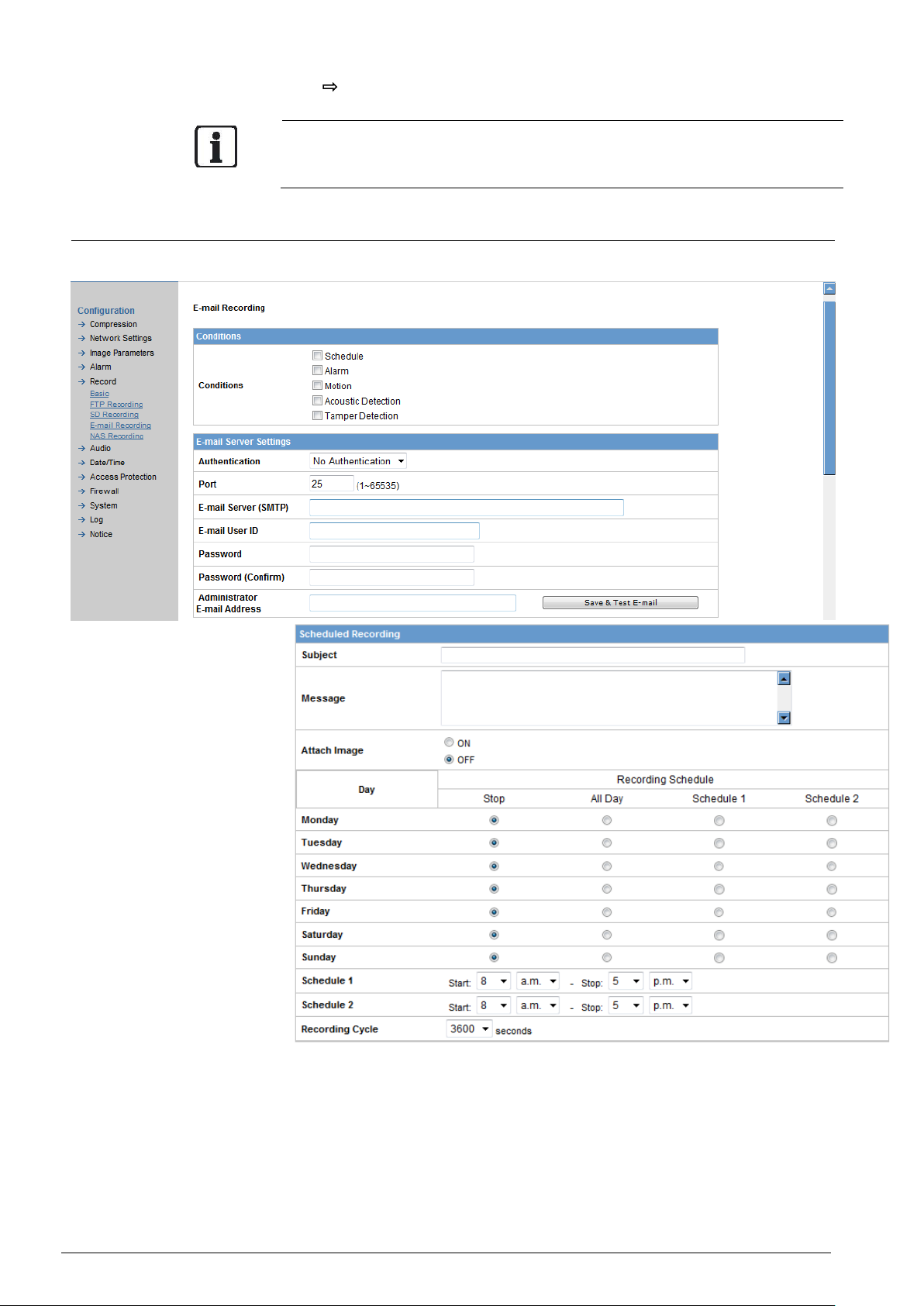
SD card backup in case of FTP failure
You can make a SD card backup even in case of an FTP failure.
The network camera automatically stores images on the SD card if they cannot
be stored on the server due to a network failure, or other error condition. The
Page 49
Configuration
© Vanderbilt 2016
49
stored images can be manually transferred to the FTP server when the problem has been resolved.
Function ON/OFF: Select "ON" to activate the SD card backup in case of FTP
failure.
Accumulation Cycle: Set a time interval in seconds (1, 2, 5, 10, 15, 30, 60 or
120 seconds) for recorded images to be stored.
Overwrite: When set to "ON", the images stored on the SD card will be overwritten when the capacity of the SD card has been reached, starting with the
oldest files.
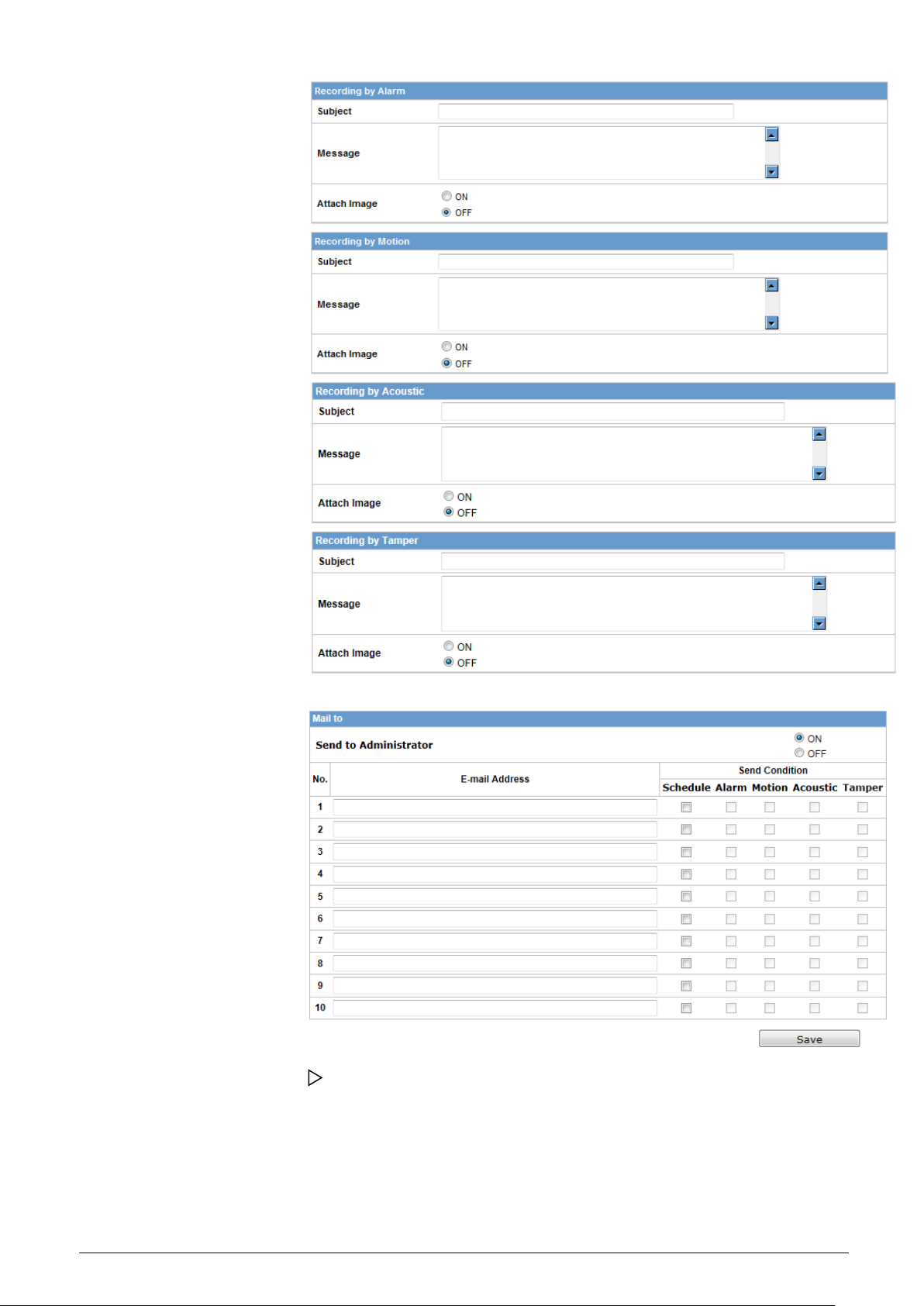
9.5.3 SD recording
Images captured according to a schedule, during alarm situations (motion detection, acoustic detection, tamper detection or network cable removed, etc),
can be stored on a SD memory card that is inserted in the network camera.
Scheduled Recording
Select the recording condition in the recording schedule table for all days
from Monday to Sunday: STOP, All Day, Schedule 1 or Schedule 2.
Recording by Network loss
1. Select network recording. During a network loss, the network camera
automatically stores images to the SD card based on your settings.
2. Recording Cycle
Set a time interval for network recording: 1, 2, 5, 10, 30, 60, 90 or 120 s.
Overwrite
ON: Data stored on the SD card will be overwritten when the capacity of
the SD card has been reached, starting with the oldest file.
OFF: Recording will be stopped if the capacity of the SD memory card is
reached during recording.
Click "Save".
Page 50
Configuration
© Vanderbilt 2016
50
The changes will be saved.
When the overwrite mode is set to "ON", files will be deleted starting with the
oldest files. If important data needs to be saved, set the overwrite mode to
"OFF".
9.5.4 Email recording
(a) You can receive images if you have set up your email account.
Page 51
Configuration
© Vanderbilt 2016
51
Set the conditions for sending email according to a schedule
If "Schedule" is selected
1. Subject - Enter a subject title for the email to be sent.
2. Message - Enter a text for the alarm message.
3. Attach Image - When "ON" is selected, you can attach image files to
your email.
4. Recording Schedule - Select the days to be included in the recording
schedule.
5. Recording Cycle - Set a time interval for scheduled recording: 30, 60,
Page 52

Configuration
© Vanderbilt 2016
52
120, 240, 600, 1200, 1800 or 3600 s.
Page 53

Configuration
© Vanderbilt 2016
53
Set the conditions for sending email in the event of an alarm
If "Alarm" is selected:
1. Subject - Enter a subject title for the email to be sent.
2. Message - Enter a text for the alarm message.
3. Attach Image - When "ON" is selected, you can attach image files to
your email.
Set the conditions for sending email when a motion is detected
If "Motion" is selected:
1. Subject - Enter a subject title for the email to be sent.
2. Message - Enter a text for the alarm message.
3. Attach Image - When "ON" is selected, you can attach image files to
your email.
Set the conditions for sending email when a acoustic is detected
If "Acoustic" is selected:
1. Subject - Enter a subject title for the email to be sent.
2. Message - Enter a text for the alarm message.
3. Attach Image - When "ON" is selected, you can attach image files to
your email.
Set the conditions for sending email when a tamper is detected
If "Tamper" is selected:
1. Subject - Enter a subject title for the email to be sent.
2. Message - Enter a text for the alarm message.
3. Attach Image - When "ON" is selected, you can attach image files to
your email.
Authentication settings
No Authentication - no restrictions
PLAIN - PLAIN is a registered SASL authentication mechanism, which is sup-
plied as a parameter to the AUTH command. The PLAIN authentication mechanism is described in RFC 2595. PLAIN is the least secure of all the SASL authentication mechanisms, since the password is essentially sent unencrypted
across the network.
LOGIN - The LOGIN mechanism is supported by Microsoft's Outlook Express,
as well as by some other clients.
TLS_TTLS- TLS is usually implemented on top of any of the Transport Layer
protocols encapsulating the application-specific protocols such as HTTP, FTP,
SMTP, NNTP and XMPP. The TLS protocol allows client-server applications to
communicate across a network in a way designed to prevent eavesdropping
and tampering. TLS can also be used to tunnel an entire network stack to create a VPN as is the case with OpenVPN.
1. SMTP Port- set "25" as default or changes to dedicated number.
2. Email Server (SMTP) - Enter your outgoing mail server (SMTP).
For further information contact your admin.
3. Email User ID - Enter your email account ID.
4. Password - Enter your email account's password.
5. Password (Confirm) - Confirm your email password.
6. Administrator email Address - Enter your email address.
7. Click "Save & Test Email" to save and test your email settings.
Mail to address list
You can send emails to multiple users according to schedule, or when an alarm
is triggered or motion, acoustic, and tampers is detected.
Page 54
Configuration
© Vanderbilt 2016
54
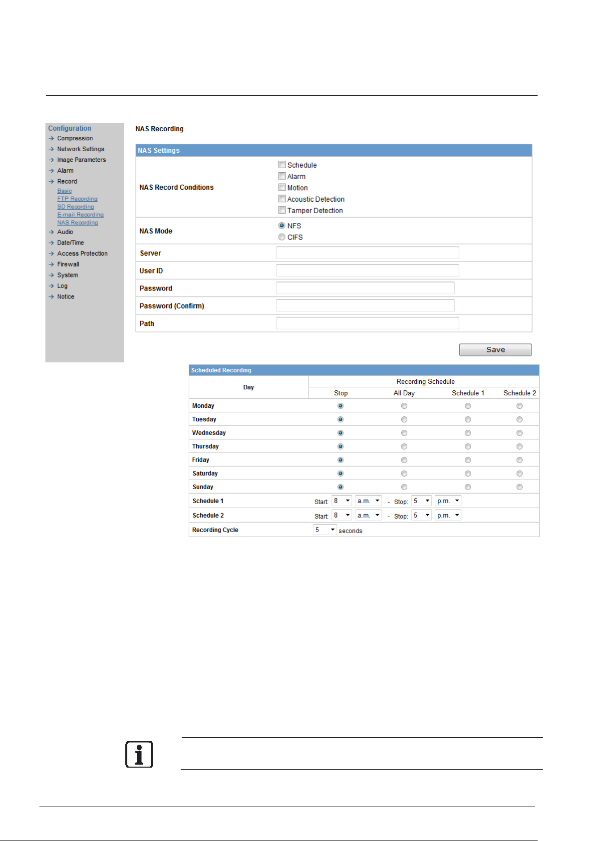
9.5.5 NAS recording
This is a method to store data on network-based storage devices.
1. Choose the recording condition:
Select the desired recording condition (Schedule, Alarm, Motion, Acoustic
detection or Tamper detection) to trigger the recording session.
Scheduled Record
Select the recording condition in recording schedule table for all days
from Monday to Sunday: STOP, All Day, Schedule 1 or Schedule 2.
2. Select the conditions you need.
3. Select the desired NAS mode: NFS or CIFS
NFS is for network storage devices using UNIX systems while CIFS is for
Windows systems.
4. Enter the storage device’s address, user ID, password, and the data
path where the data is to be stored in the Server, User ID, Password and
Path text fields, respectively.
5. Click "Save" to complete the NAS setup procedure.
Make sure all NAS devices are available in network before activating this function.
Page 55

Configuration
© Vanderbilt 2016
55
9.6 Audio
You can configure your audio settings by enabling the audio input and output.
Format
Two audio compression formats are supported: A-law and U-law.
Audio input
Audio Input: Select "ON" for receiving audio from a microphone connected
to the camera.
Audio Input Level:
– High - Increases the audio input level.
– Mid - Adjusts the audio input level to a medium level.
– Low - Reduces the audio input level.
Audio output
Audio Output: Select "ON" for delivering audio to a headphone or an active
speaker connected to the camera.
Audio Output Level:
– High - Increases the audio output level.
– Mid - Adjusts the audio output level to a medium level.
– Low - Reduces the audio output level.
Page 56
Configuration
© Vanderbilt 2016
56
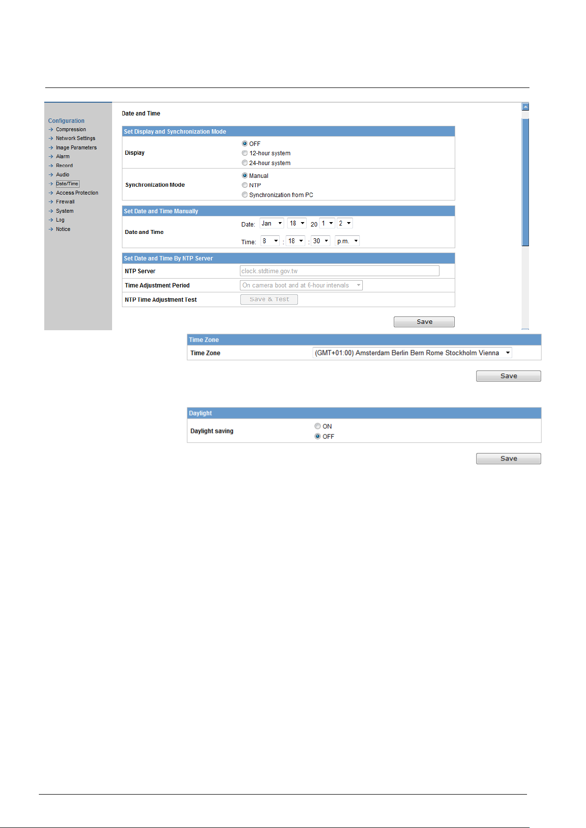
9.7 Date / Time
Display
Select "12-hour system"/ "24-hour system" to display the date/time on the
screen. The position and color are set via the camera's on-screen menu.
Synchronization Mode
– Manual:
Enter the date and time.
– NTP: For details contact your system admin.
You can also enable Network Time Protocol (NTP) via the NTP server.
Enter a host name for the NTP server, select a time adjustment period,
and click "Save & Test" to start testing the NTP function.
– Synchronization from PC:
The system date/time can be synchronized via the PC settings.
Page 57

Configuration
© Vanderbilt 2016
57
Set Date and Time By NTP Server
– NTP server:
Input IP address or URL of the dedicated NTP server.
Note: Please make sure disable SD recording function before you en-
able NTP synchronization mode.
– Time adjustment period: Select interval to synchronize with the NTP
server.
Time zone:
Select the country where the unit is located.
Daylight saving
Select "ON" to activate the daylight-saving function if you are in a daylight-
saving time zone (effective for NTP mode only).
9.8 Access protection
9.8.1 Administrator
Administrator functions
Select "Administrator Functions" in the setting menu. You can set up the
system password, user language and logoff time.
Password
The default settings for system admin ID and password are as follows:
Admin ID: admin
Password: admin
You can create your own Admin ID and password in these fields
Language: English.
You can select from 5 languages.
Logoff Time
Set the period of time during the user leaving the camera configuration in-
terface for camera to logoff.
Page 58

Configuration
© Vanderbilt 2016
58
9.8.2 User list
Besides the administrator, general users can access the camera once they
have been assigned a user ID and password by the system administrator.
You can add users by assigning them individual IDs and passwords in the "User Settings" field and adding them to the user list.
User level:
Advanced users can see the live picture and perform basic functions
(e.g. PTZ control, etc.).
Users can only view the live image; they have no authorization to per-
form any functions.
9.9 Firewall
9.9.1 IP Address filter
1. Enter the IP address (es) to be processed by the firewall system in the
IP address field(s). Up to 10 addresses can be set.
2. Enable the IP address (es) in the list which are to pass the firewall filter
by selecting "ON".
3. Select either "Allowed" or "Denied" or "OFF".
Allowed: The listed IP addresses will pass the firewall.
Page 59

Configuration
© Vanderbilt 2016
59
Denied: The listed IP addresses will be rejected by the firewall.
Page 60

Configuration
© Vanderbilt 2016
60
9.9.2 Forbidden ports
All the listed ports that enabled (set to "ON") will be rejected by the firewall.
9.9.3 Forbidden protocols
ICMP or UDP protocols can be rejected by the firewall if assigned.
Page 61

Configuration
© Vanderbilt 2016
61
9.10 System
9.10.1 Settings
SD card format: Click "format" to erase information off of the SD card.
Logo image upload: Upload logo image. The logo image accepts a *.gif &
*.bmp file and the file size have to be below 10K (10x1024).
CGI-Lock is a system security setting.
- ON: User should pass authorization to activate CGI-command action.
- OFF: User can freely use any CGI-commands without any authorization.
Page 62

Configuration
© Vanderbilt 2016
62
9.10.2 Update
You can update the system firmware once the update file is available. It is the
customer's responsibility to update the firmware. All camera motions will be
shut down during the firmware update. Close all dialogs and screens before
starting a firmware update. Never disconnect the power cable and the LAN cable during the firmware update process. Rebooting the camera after a firmware
update may take approx. 15 minutes. After you finish a software update, please
reboot your computer at first.
Do not disconnect power during a SW update.
Otherwise, it causes SW update failure and you have to send back your
camera to Vanderbilt maintenance.
Page 63

Configuration
© Vanderbilt 2016
63
9.10.3 Configuration
Camera configuration information can be exported and saved to a personal
computer. It can also be imported from the personal computer to network cameras.
Import - Click on "Import" and select the configuration settings file to be
imported to your network camera.
Export - Click on "Export" and select the directory to save the file on
your computer.
Factory Default - Clicking on "Default" in the setup.
Basic IP camera network settings (e.g. IP address and camera name) will not
be reset when a software reset is made. Also the export configuration settings
and the settings for import and factory default.
Network Camera Reboot - When you click on "Reboot" the following
message will pop up: "This will reboot the camera. Are you sure?” Click
"OK" to reboot the network camera.
Page 64
Configuration
© Vanderbilt 2016
64
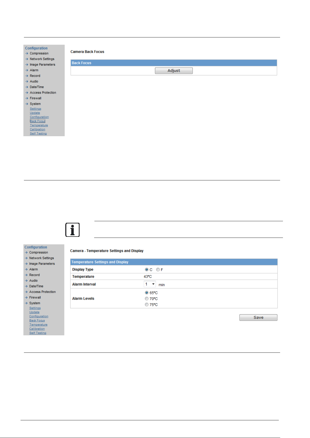
9.10.4 Back focus
Click "Adjust" button, the IRIS of lens will be fully open and a live picture screen
popup. Now you can start to adjust the lens back focus, click "close" button to
exit the screen when finishing the adjust session.
9.10.5 Temperature
There are options for displaying the temperature: Celsius and Fahrenheit. The
current internal temperature of the camera is displayed. If the temperature exceeds the limit value, an e-mail will be sent depending on the temperature notification interval setting. If "0" is selected, the e-mail will be delivered only once.
When the temperature of the camera is too high, for example above 70°C,a
warning message will pop up.
9.10.6 Calibration
Click Calibration button for calibration DC IRIS testing. A window pops up and
camera begins calibrating automatically. After calibration finished, click Close
to exit calibration DC IRIS testing page.
Page 65

Configuration
© Vanderbilt 2016
65
9.10.7 Self-Testing
The status of the system can be displayed here.
Page 66
Configuration
© Vanderbilt 2016
66
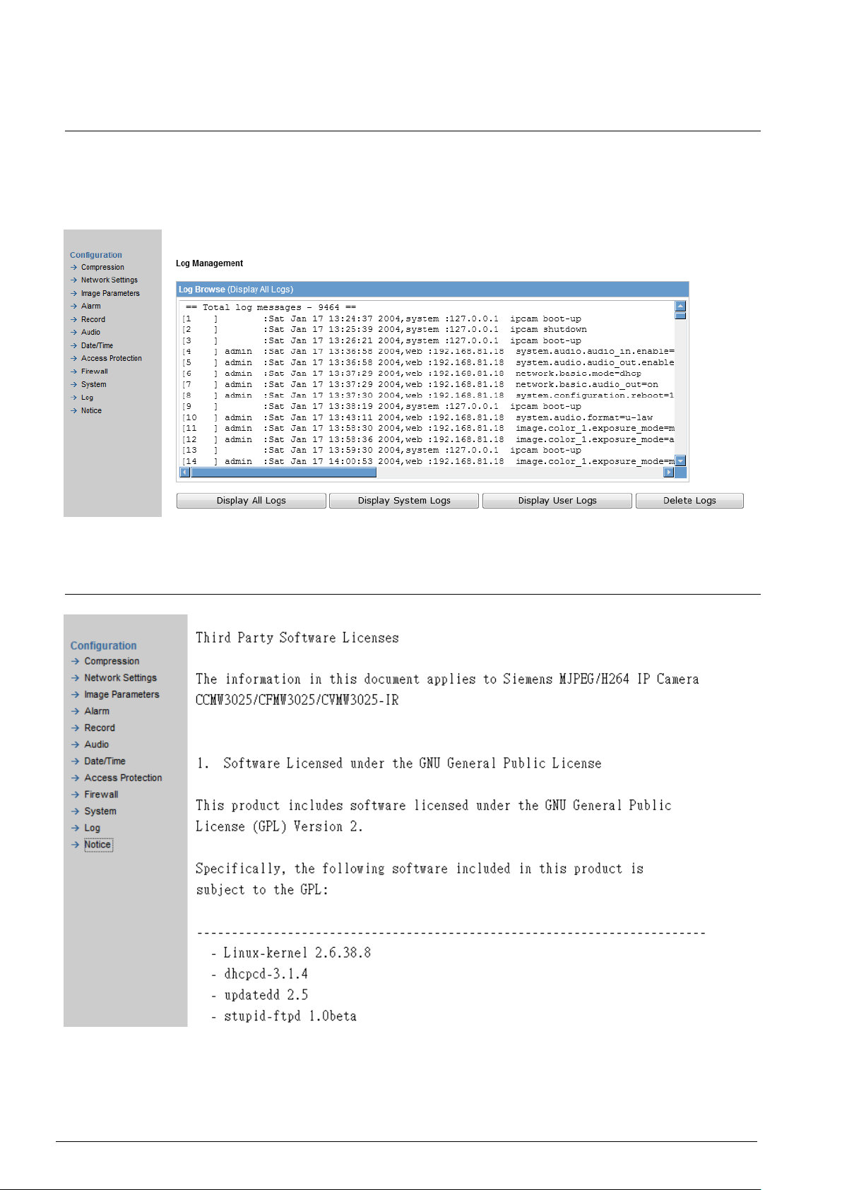
9.11 Log
Event log
Select the menu sequence Settings > Log. By clicking the buttons "Display All
Logs", "Display System Logs", "Display User Logs", "Delete logs" the corresponding logs will be displayed and can be processed.
9.12 Notice
Page 67

Utility program application
© Vanderbilt 2016
67
10 Utility program application
10.1 NAS player setup
The application for playing back NAS files can be found on the DVD that is included in the delivery.
Prerequisite: NAS recording has been configured.
1. Click on the green cross button and select the path of the NAS file to
be played back.
2. Click "Play"
3. Click "Stop"
10.2 Audio recording setup
This application is found on the DVD that is included in the delivery. You can
record a new voice file and upload it to the network camera. This application
can generate alarm out events. After you finish audio record, please control
alarm audio setting.
To record audio, proceed in the following manner:
Prerequisite: Audio recording has been configured.
1. Click on the green cross button and select the path to which to save
the *.wav file.
2. Make sure a microphone is installed before you start recording your
voice.
3. Click on the red button and start recording your voice.
4. Click "Stop".
10.3 Firmware update setup
This application is found on the DVD that is included in the delivery. You can
update multiple network cameras simultaneously. To update firmware, proceed
in the following manner:
Prerequisite: The firmware update software has been installed.
Page 68
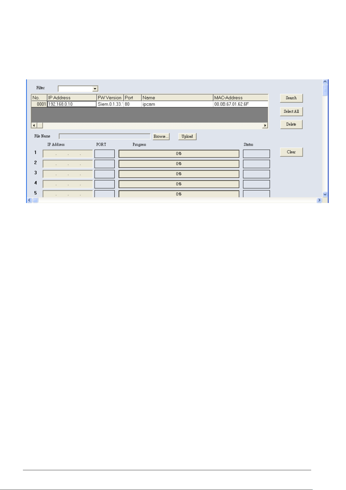
Utility program application
© Vanderbilt 2016
68
1. Select the software version from the "Filter" drop-down list.
2. Select the network camera you want to update. The upgrade tool sup-
ports the simultaneous firmware update of up to 100 network cameras.
3. Click on "Browse…" and select the software version for the network
camera.
4. Click on "Upload" to start the firmware update.
Current FW version: X.0.1.33
Page 69

Maintenance
© Vanderbilt 2016
69
11 Maintenance
The camera is maintenance-free.
There is a limitation of rewrites that is possible with the SD memory
card. Replacing the SD memory card when performing periodic mainte-
nance on the camera is recommended, at latest after 10,000 writing cy-
cles.
Small amounts of dirt or dust can be cleaned from the camera using a
clean soft cloth. Do not touch the lens area.
If the surface is touched accidently use a soft cloth moistened with al-
cohol to clean it.
Defective modules should be sent to the nearest Vanderbilt office to be
forwarded to the service centre.
Page 70

Disposal
© Vanderbilt 2016
70
12 Disposal
All electrical and electronic products should be disposed of
separately from the municipal waste stream via designated
collection facilities appointed by the government or the local
authorities.
This crossed-out wheeled bin symbol on the product means
the product is covered by the European Directive
2002/96/EC.
The correct disposal and separate collection of your old appliance will help prevent potential negative consequences for
the environment and human health. It is a precondition for
reuse and recycling of used electrical and electronic equipment. For more detailed information about disposal of your
old appliance, please contact your city office, waste disposal
service or the shop where you purchased the product.
Page 71

Keyword index
© Vanderbilt 2016
71
Keyword index
Administrator, 20, 54
Alarm output, 42
Audio, 28
Audio recording setup, 62
Authentication, 30
Automatic Exposure, 34
AWB, 35
Bit rate, 26
Bonjour Use, 28
Camera name, 27
Cleaning, 8
Compression ratio, 26
Contrast, 35
Cropping settings, 37
Daylight, 54
Day-Night Delay, 35
Day-Night Level, 35
Day-Night Settings, 35
DDNS settings, 29
DHCP, 27
DHCP server, 17
Display, 53
Email Server, 50
Export, 59
Factory default, 14, 59
Firewall, 55
Firmware update setup, 62
Forbidden ports, 56
Forbidden protocols, 56
Frame rate, 26
FTP Recording, 45
FTP server, 29, 46
GOP, 26
H264, 26
Image mode, 26
Import, 59
Internet browser, 21
Internet options, 21
IP address, 21
IP address filter, 55
Ipv6 address configuration, 27
JPEG, 26
Login dialog, 20
Manual Gain, 35
Motion detection, 40
NAS player setup, 62
Noise Reduction, 35
Overwrite, 47
Password, 54
Picture flip, 36
Picture mirror, 36
Power supply, 15
Preset image, 35
Primary DNS, 27
R Gain, B Gain, 35
Reboot, 59
Resolution, 26
RTSP port number, 30
Saturation, 35
SD recording, 47
Secondary DNS, 27
Sensor characteristics, 9
Sharpness, 35
Shutter speed, 34
Subnet Mask, 27
Synchronization mode, 53
Temperature, 59
Transfer type, 30
Unit home page, 22
UPnP Use, 28
User, 55
Webcam IP Manager, 18
Page 72

Issued by Vanderbilt
Clonshaugh Business and Technology Park
Clonshaugh
Dublin 17
Ireland
www.vanderbiltindustries.com
© Vanderbilt 2016
Data and design subject to change without notice
Supply subject to availability
Document no.: C-300883
Document version: 2.0
Edition: 17/2/2016
 Loading...