

Page 1
EN
CCMS2010-IR
2 Megapixel Compact IP Camera with
IR illumination (PoE)
Quick Installation Guide
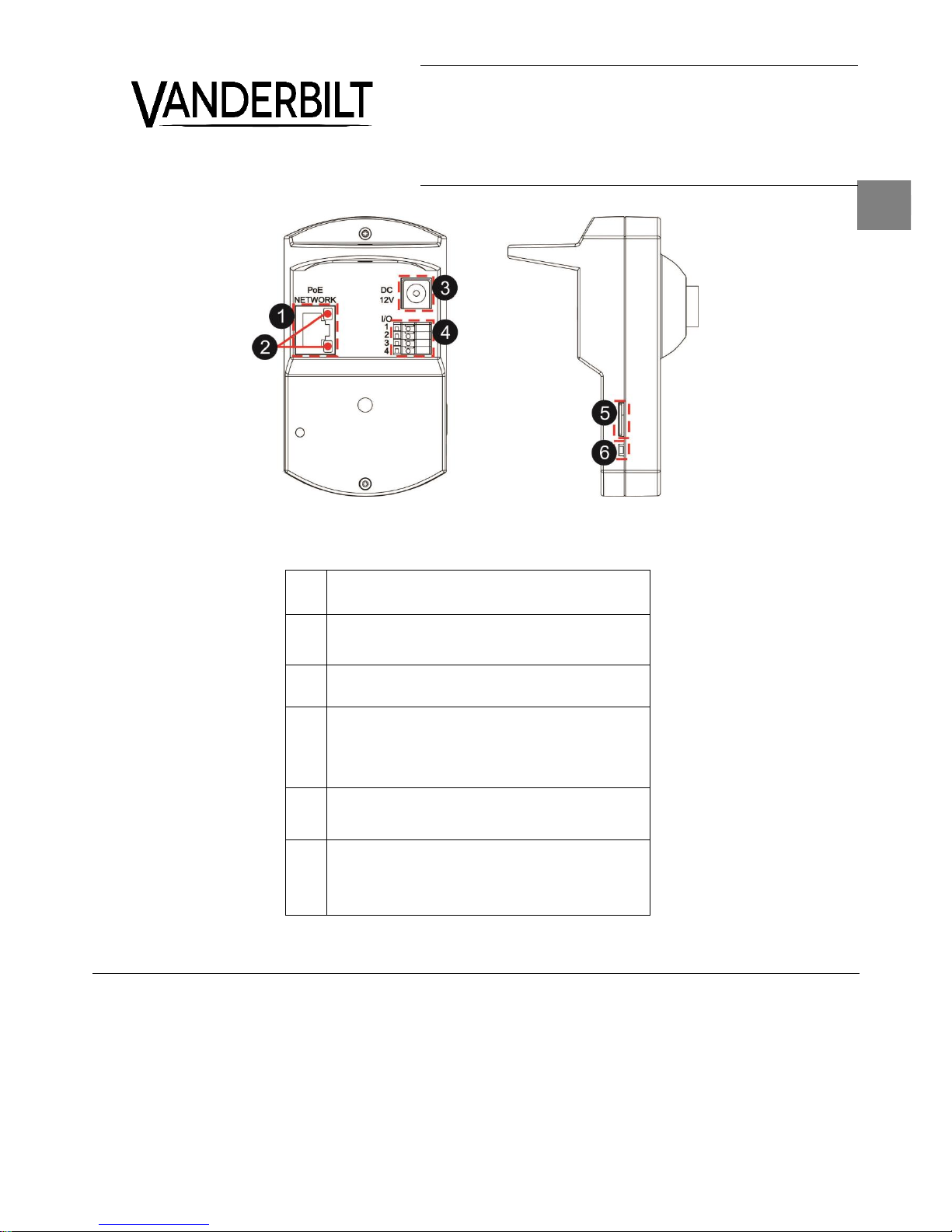
1
PoE Network
For Ethernet cable and PSE connection
2
Network LEDs
Network connection and activity indication
3
DC 12V Connector
For power connection
4
Alarm I/O
1- Alarm Output +
2- Alarm Output –
3- Alarm Input +
4- Alarm Input −
5
Micro-SD Card Slot
For videos and snapshots storage
6
Default Button
Press the button with a proper tool for at least 20 seconds
to restore the system.
About this document
This guide outlines the most important information regarding the installation of the camera. For instructions regarding the configuration and further
mounting options please refer to the User manual on CD.
Page 2
CCMS2010-IR, 2 Megapixel Compact IP Camera with IR illumination (PoE)
© Vanderbilt 2016
2
EN
Package contents
IP compact Camera (PoE)
Resource kit CD
Quick Install Guide
Wall Bracket
Jack/Terminal adapter
12VDC PSU
Micro SD card (4GB)
Target readers
This installation instruction is only intended for use
by installers who have an adequate working
knowledge of video systems!
Installation must be performed by qualified service
personnel in accordance with all local codes.
Safety
General safety precautions
Read the general safety precautions before
installing/configuring/operating the device.
Keep this document for reference.
Always pass this document on together with the
product.
Please take into account any additional country-
specific, local laws, safety standards or
regulations concerning installation, operation
and disposal of the product.
Use only spare parts and accessories that have
been approved by the manufacturer.
Transport
Keep the packaging material for future
transportation.
Do not expose the device to mechanical
vibrations or shocks.
Installation
Refer to a qualified electrician for installation.
The environmental conditions recommended by
the manufacturer must be observed. See
"Technical data".
Do not operate the device close to sources of
powerful electromagnetic radiation.
The device should only be used for indoor
applications.
The mounting surface must be solid and
noncombustible.
Danger of electrical shock/fire hazard/damage to
the device due to incorrect connection
Connect the device only to a power source that
complies with SELV requirements and with the
Limited Power Source requirements to EN
60950-1.
Service and maintenance
The camera is maintenance-free.
Do not attempt to service or modify this device
yourself. Refer this work to qualified service
personnel.
Use a soft, dry cloth to remove fingerprints or
dust from the camera. Do not use liquid
cleaners or sprays that contain alcohol, spirit or
ammonia.
Power supply
Ensure that the AC power supply is stable and within
the rated voltage of the unit. Use an uninterrupted
power supply (UPS) to ensure a continuous function
of the unit in the event of power dips on the AC
mains supply.
Details for ordering
Type
CCMS2010-IR
Part no.
V54561-C112-A100
Designation
2MP Compact IP Camera with
IR (PoE)
Further products and accessories can be found in
the Internet: https://is.spiap.com/products/video.html
Installation
Step 1: Power up the Camera
To power up the IP Camera, please use the DC 12V
adaptor (provided) and connect it to the camera and
the power outlet. Alternatively, connect the Ethernet
cable to the PoE Network connector of the camera,
and plug the other end of the cable to a PoE switch.
NOTE: If PoE is used, make sure Power Sourcing
Equipment (PSE) is used in the network.
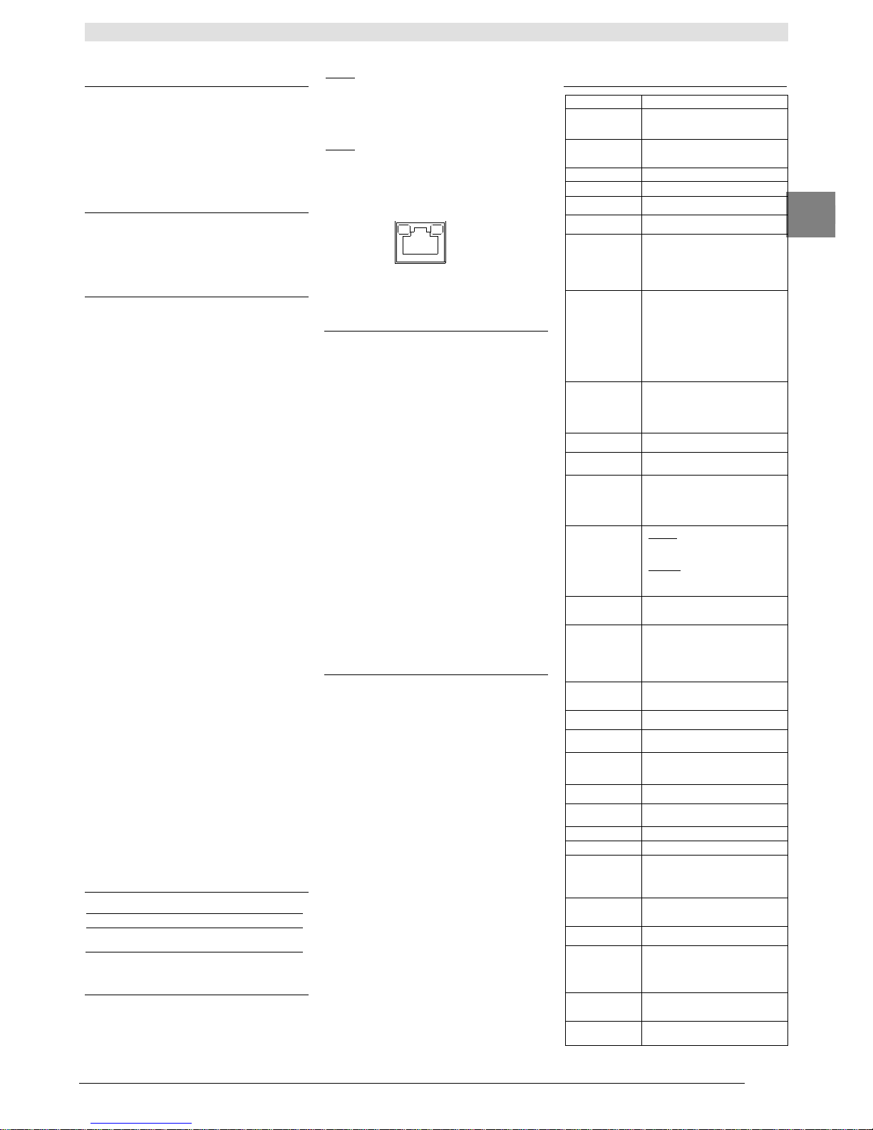
Step 2: Ethernet Cable Connection
Connect one end of the Ethernet cable to the PoE
Network connector of the camera, and plug the other
end of the cable to the network switch or PC.
NOTE: In some cases, Ethernet crossover cable
might be needed when connecting the IP Camera
directly to the PC.
Check the status of the link indicator and activity
indicator LEDs. If the LEDs are unlit, please check
the LAN connection.
Green Link Light indicates good network connection.
Orange Activity Light flashes for network activity
indication
Before Login to the IP Camera
A client program will be automatically installed on the
PC when connecting to the IP Camera. Before
logging in to the IP Camera, please ensure
downloading the ActiveX control is allowed by either
changing the ActiveX controls and plug-ins or setting
Internet’s security level to default. For further details,
please refer to the User Manual of the IP Camera.
(a) ActiveX Controls and Plug-ins
Settings
Step 1: Start the Internet Explorer (IE).
Step 2: Select <Tools> from the main menu of
the browser. Then click <Internet Options>.
Step 3: Click the <Security> tab and select
“Internet”, and click <Custom level> to change
ActiveX settings.
Step 4: Set “ActiveX controls and plug-ins” items
to <Prompt> or <Enable>.
(b) Internet Security Level
Step 1: Start the Internet Explorer (IE).
Step 2: Select <Tools> from the main menu of
the browser. Then click <Internet Options>.
Step 3: Click the <Security> tab and select
“Internet.”
Step 4: Down the page, click “Default Level” and
click “OK” to confirm the setting. Close the browser
window, and open a new one later for accessing the
IP Camera.
IP Camera Login
The IP Camera’s default IP address is:
192.168.0.10. Therefore, to access the IP Camera
for the first time, set the PC’s IP address as:
192.168.0.XXX; for example:
IP Address: 192.168.0.100
Subnet Mask: 255.255.255.0
(a) Login ID and Password
Key in the IP Camera’s IP address in the URL
bar of the Web browser window and press
“Enter”.
Enter the default user name admin and
password admin in the prompt request
dialogue. Note that user name is case sensitive.
(b) Install the ActiveX Control
After connecting to the IP Camera, the request
for installing the ActiveX control will appear just
below the URL bar.
Right click on the information bar, and click
“Install ActiveX Control…” to permit ActiveX
control installation.
In the pop-up security warning window, click
“Install” to start downloading Vanderbilt Viewer
software.
Click “Finish” after Vanderbilt Viewer installation
is complete.
Firmware check/update
Please check the camera firmware against the
current FW version at:
https://is.spiap.com/products/video.html.
Technical data
Image Sensor
1/2.7” Progressive CMOS
Effective
Pixels
1920 (H) x 1080 (V)
Minimum
Illumination
Colour: 0.2 lux (F2.0) 30 IRE
B/W: 0.02 lux (F2.0) 30 IRE
White Balance
Manual / AWB / ATW
Shutter Speed
1 ~ 1/10000 sec
Focal Length
2.8 mm
F Number
F2.0
Multiple
Languages
German / English / Spanish /
French /Italian / Japanese /
Korean / Portuguese / Russian
/ Simplified Chinese /
Traditional Chinese
Image
Settings
Backlight Compensation, White
Balance, Noise Reduction (3D),
Wide Dynamic Range, Privacy
Mask, Brightness, Exposure,
Sharpness, Contrast,
Saturation, Hue, Digital Zoom,
Motion Detection, ICR + IR
LED, Tampering Alarm
Audio
Two-way Audio
Built-In Microphone and
Speaker
Compression: G.711 / G.726
Interface
RJ-45, 10/100 Mbps
Video
Compression
H.264 / MJPEG
Video
Streaming
Dual Streams- H.264 + H.264 /
H.264 + MJPEG
Quad Streams- H.264 x 4 /
H.264 x 3 + MJPEG
Video
Resolution
H.264- Full HD 1080P / SXGA /
HD 720P / XGA / SVGA / D1 /
VGA / CIF
MJPEG- Full HD 1080P /
SXGA / HD 720P / XGA /
SVGA / D1 / VGA / CIF
Frame Rate
Dual Streams- 1080P (30/25
fps) + D1 (30/25 fps)
Network
Protocols
IPv4/v6, TCP/IP, UDP, RTP,
RTSP, HTTP, HTTPS, ICMP,
FTP, SMTP, DHCP, PPPoE,
UPnP, IGMP, SNMP, QoS,
ONVIF, ARP
Security
Authorization
HTTPS / IP Filter / IEEE
802.1X
Alarm Input
1 Set, 5V 10kΩ pull up
Alarm Output
1 Set, Photo Relay Output
Event
Notification
HTTP / FTP / SMTP
microSD
microSDHC 32GB Support
Supported
Web Browser
Internet Explorer (10+) /
Chrome / Firefox / Safari
User Account
20
Password
User and Administrator
Built-in IR
Illuminator
Working distance : up to 5m
(dependent on scene
reflectance)
Wavelength: 850 nm
Power
Connection
PoE / DC Jack
LED Indicator
Power / Link / ACT
Connectors
Alarm: 4 Pin Terminal Block
(Female)
Power: DC Jack
Ethernet: RJ45
Operating
Temperature
-10°C ; +50°C
Humidity
10% ~ 90%, No Condensation
Page 3

CCMS2010-IR, 2 Megapixel Compact IP Camera with IR illumination (PoE)
© Vanderbilt 2016
3
EN
Dimension
(without
bracket)
96.51 x 56.00 x 61.40 mm
Weight
120 g
Power Source
PoE / DC 12V
Power
Consumption
<4W
Approvals
CE
Disposal
All electrical and electronic products
should be disposed of separately from
the municipal waste stream via
designated collection facilities
appointed by the government or the
local authorities.
Page 4

CCMS2010-IR, 2 Megapixel Compact IP Camera with IR illumination (PoE)
Issued by Vanderbilt
Clonshaugh Business and Technology Park
Clonshaugh
Dublin 17
Ireland
www.vanderbiltindustries.com
© Vanderbilt 2016
Data and design subject to change without notice
Supply subject to availability
Document no.: C-300965
Document version: 2.0
Edition:22/03/2016
EN
 Loading...