

Page 1
© 2017 Vanderbilt 1 / 4 021_AGB800-AM_I-200259_EN
Acoustic Glass Break Detector
with Antimasking
Instruction and installation manual AGB800-AM
EC DECLARATION OF CONFORMITY
Hereby, Vanderbilt International (IRL) Ltd declares that this
equipment is in compliance with all relevant EU Directives for
CE marking. From 20/04/2016 it is in compliance with Directive
2014/30/EU (Electromagnetic Compatibility Directive).
The full text of the EU declaration of conformity is available at:
http://pcd.vanderbiltindustries.com/doc/intrusionaccessories
DESCRIPTION
AGB800-AM is an acoustic glass break detector giving an
alarm when glass is smashed at intruder attempts through windows, doors and glazed walls.
The detector is based on advanced microcontroller technology
and programmed to take a lot of relevant acoustic factors into
account: The Digital Room Compensation (DRC). This makes
the detector able to distinguish between a true glass break and
other irrelevant sounds.
The detector is for indoor use. The coverage distance is 1–9 m.
The coverage angle is 165º, which means that one detector can
protect several windows in the same room. The detector can
be mounted in the ceiling or on a wall with a free “line-of-sight”
to the window being protected.
AGB800-AM is equipped with an AM function, a separate relay,
which gives an alarm at sabotage of microphone.
AGB800-AM is certified according to EN 50131-2-7-1:2012,
security grade 3.
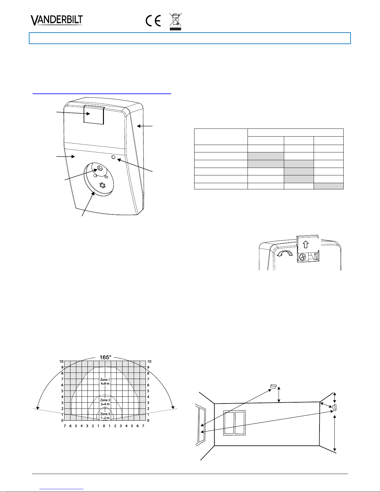
Coverage area in the acoustic room Zone 1–3
CONNECTION TO A 24-HOUR LOOP
The detector is constructed for continuous supervision and is
extra resistant to different acoustic disturbances. It will function
well in most environments. However in rooms with very high
rates of disturbances as in industrial workshops and gyms, it is
recommended to test the detector for 3–4 weeks before deciding to use it continuously. In rare cases a combination of random sounds can trigger an alarm.
SIGNALLED EVENTS
Detector has two relays and one micro-switch to signal detected and processed events to control panel in prioritised order
as following signals:
Glass break – signalled by INTRUSION relay
Low power supply voltage or self-test fail – signalled by
FAULT relay
Masking – signalled by INTRUSION and FAULT relay
Sabotage is signaled independently by TAMPER micro-switch.
Event
Signal sent by relay or micro-switch
INTRUSION
FAULT
TAMPER
No stimulus
Closed
Closed
Closed
Intrusion
OPEN
Closed
Closed
Masking
OPEN
OPEN
Closed
Low Supply Voltage
Closed
OPEN
Closed
Local Self-Test Fail
Closed
OPEN
Closed
Tamper
Closed
Closed
OPEN
SPECIAL TOOLS
In most rooms (e.g. offices) no special tools are required during
the installation. In rooms with complicated acoustics it is recommended to use the ADT700 tester. ADT700 can also be
used for function test and annual service.
OPENING THE DETECTOR
MOUNTING INSTRUCTIONS
Detector should be installed on a ceiling or on a wall oppo-
site to the glass to be protected
Clear “line-of- sight” between the “microphone” of the de-
tector and the glass is required
Distance between the glass and the detector should be 1–9m
Detector should be installed min. 50cm from a corner
Detector should be installed min. 1m over the floor
Detector should be installed min. 30cm from the ceiling (at
wall mounting)
Detector should be installed on a flat surface, which is free
from objects in a radius of 50cm from the detector
Detector should not be installed close to air vents or big
sound reflecting obstacles
Never mount the detector in the corners
Base
Cover
Cover
lock
LED
Microphone
Masking detection device
Slide the lock cover up
Loosen the screw
Pull cover to open
min. 0.5 m
max
.
8
.
5
m
max
. 9
m
min. 0.3 m
min. 0.5 m
min.
1 m
Location for wall or ceiling mount
Page 2
© 2017 Vanderbilt 2 / 4 021_AGB800-AM_I-200259_EN
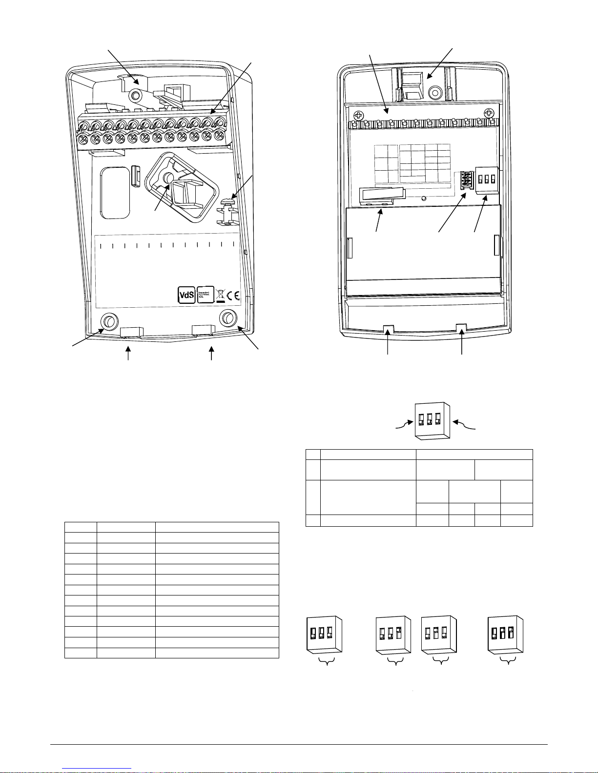
DETECTOR BASE AFTER REMOVAL OF THE COVER
INSTALLATION
1. Choose the best mounting position on the wall or ceiling.
2. Loosen the cover screw and remove the upper part
3. Use the bottom part as a template and mark the place of
the holes of with a pen
4. Use a 2.5mm drill for the self-tapping screws provided. If
necessary, use wall anchors
5. If necessary, cut out the marked “knockout hole” on the
back of the base with a pair of pliers
6. Pull the wiring cable through the “knockout hole” in the bot-
tom plate
7. Connect the wires to the screw terminals
Pin
Marking
Function
1
(-)
Ground
2
(+)
Plus 7 to 30 V DC
3
D/N
Day and Night control of LED
4
INTRUSION
INTRUSION relay output C
5
INTRUSION
INTRUSION relay output NC
6
Spare
Spare contact (unconnected)
7
FAULT
FAULT relay output C
8
FAULT
FAULT relay output NC
9
Spare
Spare contact (unconnected)
10
TAMPER
Tamper switch output C
11
TAMPER
Tamper switch output NC
12
Spare
Spare contact (unconnected)
8. Use the cable strap provided to fix the wiring cable to the
detector.
9. Fix the detector firmly to the base with the enclosed
screws.
COVER SEEN FROM BELOW
UNDERSTANDING THE DIP SWITCH
#
Function
Setting
1
INTRUSION relay
mode
ON – Latch
OFF – Auto
2
Range setting
4–9m
Zone1
2–4m
Zone 2
1–2m
Zone 3
OFF
OFF
ON
ON
3
Range setting
OFF
ON
OFF
ON
DIP1=ON: INTRUSION relay mode ON means the INTRUSION relay will Latch and be open in alarm.
DIP1=OFF: INTRUSION relay mode OFF means the INTRUSION relay will be auto reset after 2 seconds in alarm.
10. Set the desired range, i.e. the detector sensitivity setting
by using the DIP switch no 2 and 3.
11. Check the window constructions and note what kind of
glass is used and especially in the pane closest to the
room.
Mounting
hole #2
Slots for assembling
the cover hooks
Mounting
hole #3
Mounting
hole #1
Terminal
block
Cable jacket
“knock-out”
Cover
screw
4
5
INTRUSION
7
8
FAULT
10
11
TAMPER
1
(
-
)
2
(+)
3
D/N
6
Spare
9
Spare
12
Sp.
Acoustic Glass Break Detector
with Antimasking
EN 50131
-
2
-
7
-
1 Security Grade 3
EN 50130
-
5 Environmental Class I
VdS 117504
AGB 800
-
AM
Vanderbilt Intl (IRL) Ltd.
Clonshaugh Business Park
Clonshaugh, Dublin, D17 KV84
Ireland, V54535
-
Z130
-
A100
Terminal block pins
Tamper
switch
DIP
switch
PC
interface
Hooks holding the cover to the base
Cover lock
AGB 800
-AM
PC interface
USB
-
link
12
Sp.
11
9
Sp.
7
6
Sp.
1
(
-
)
2
(+)
3
D/N
8
10
FAULT
TAMPER
4
5
INTRUSION
DIP Switch Settings
Acoustic Glass Break
Detector w. Antimasking
4
-
9 m
OFF
OFF
OFF
2
Range
3
ON
2
-
4 m
ON
OFF
ON
ON
1
-
2 m
Relay
mode
Latch
Auto
Reset
1
OFF
ON
DIP
Switch
1
2
3
Zone
Setting
ON
1
2
3
ON
1
2
3
INTRUSION relay
mode (DIP1)
Range setting
(DIP2, DIP3)
4–9m, Zone 1
OFF, OFF
2–4m, Zone 2
OFF, ON or ON,
1–2m, Zone 3
ON, ON
ON
1
2
3
ON
1
2
3
ON
1
2
3
ON
1
2
3
Page 3

© 2017 Vanderbilt 3 / 4 021_AGB800-AM_I-200259_EN
SUGGESTED SETTINGS OF THE DETECTOR DEPENDING ON WINDOW DESIGN AND TYPE OF GLASS:
Check the window constructions and note what kind of glass is
used and especially in the pane closest to the room.
Single glazed (float & tempered) – Set the detector at the
measured distance from the glass to the detector.
Double glazed (float & tempered). If there are high disturb-
ances in the surroundings – set the detector at the measured distance from the glass to the detector. At normal or
low disturbances – the detector shall be set at Zone 1.
Double glazed where the inner pane is covered with secu-
rity film – Set the detector at Zone 1 apart from the meas-
ured distance.
Triple glazed (float & tempered) – Set the detector at Zone
1 apart from measured distance.
Laminated glass – Set the detector at Zone 1 apart from
the measured distance.
Window design
Glass type of pane inside room
Range
1–2m
2–4m
4–9m
1
Single glazed
Float & tampered
Zone 3
Zone 2
Zone 1
2
Double glazed
Float & tampered
High disturbances
Zone 3
Zone 2
Zone 1
Low disturbances
Zone 1
3
Triple glazed
Float & tampered
Zone 1
4
Double glazed with security film
Float with security film
Zone 1
5
Single & multi-glazed
Laminated
Zone 1
CHECK THE SETTINGS WITH ADT700 TESTER
If the detector is placed too far or too close from the glass, it
will not respond. At DRC testing the LED of the detector will
flash 1, 2 or 3 times to show it is in a certain Zone. If it does not
flash a better place must be selected.
1. Put the cover on and make sure it hooks properly into the
base of the detector.
2. Apply power – LED will now indicate your range setting by
blinking 1–3 times.
3. Use ADT700 to test and calibrate the detector for optimal
position.
TESTING AND CALIBRATING
ADT700 tester is a specially developed tool for calibrating and
adjusting the detector AGB800-AM for optimal function in the
acoustic room – the DRC Digital Room Compensation procedure. When testing the detector settings you do not need to
open it again as the tester will communicate with the detector
acoustically. Never test the AGB800-AM with a cover disassembled from a base. Make sure the cover is fastened properly.
Caution: Do not use the ADT700 tester in proximity to your
ears as the tester produces loud noises.
DIGITAL ROOM COMPENSATION PROCEDURE
Prepare the acoustic detector for DRC by setting the D/N line
(if used) in DAY mode – D/N line should be left open or Low.
1. Press the START button of the ADT700 tester to put the
power on. Green LED will light.
2. Hold the tester 1 to 3m from the detector and aim the
speaker at it.
3. Press the START button once more to initiate the DRC
mode. The LED on the detector will start to flicker.
4. Go to the furthest distance (max. 9m) of the glass to be
protected and aim the speaker at the detector.
5. The DRC range calculated by the detector will be displayed as a number of pulses from 1 to 3.
Press the DRC button to send a DRC signal out. Make this 2–
10 times from different angles of the protection area for optimal
capability. The LED will flash confirming it has received the signal. The LED will then start to blink and flicker. The DRC range
calculated by the detector will be displayed as a number of
pulses from 1 to 3. In case of too weak or too strong signals
outside the compensation range (means that the detector is
placed too close or too far from the object to be protected), the
detector will then not show DRC range.
6. Press the STOP button from a distance of 1 to 3m from the
detector to terminate the DRC procedure.
If DRC range measured by the detector is different from actual
DIP-switch settings, the LED will continue to blink 1–3 times
showing the correct range number to be set in the detector.
The LED blinks 1 time: set to Zone 1 (4–9 m)
The LED blinks 2 times: set to Zone 2 (2–4 m)
The LED blinks 3 times: set to Zone 3 (1–2 m)
Insert cover hooks
into slots in the base
Close the cover
Tighten the locking screw
Slide down the lock cover
CLOSING THE DETECTOR
Page 4

© 2017 Vanderbilt 4 / 4 021_AGB800-AM_I-200259_EN
PROTECTING SEVERAL WINDOWS BY ONE DETECTOR
Detector can protect several windows in one room if the windows are within the coverage area. Make independent DRC
test for each window to be protected. Follow the procedure
above for each window. The detector shall be set to the lowest
Zone number that is the longest range from the detector.
TIMEOUT
Both the AGB800-AM detector and ADT700 tester are
equipped with a timeout feature. The AGB800-AM will stop the
DRC mode and the ADT700 will switch off power if no activity
has happened within 3–4 minutes.
D/N CONTROL (Day/Night)
The D/N makes it possible to remote control the alarm indications of the detectors and remote reset during DAY->NIGHT
transition. The D/N increases the security of the detector, as it
enables the alarm indications to be concealed in NIGHT mode
without any influence on the relay function.
SELF-TEST
Detector is continuously checking all vital parts responsible for
proper detection of glass break signal using internal self-test
procedure.
ANTI-MASKING
Test of antimasking system:
1. Put the power on. Seal microphone completely with elastic
material like chewing gum or isolation tape.
2. INTRUSION and FAULT relays will open after max. of 180
s signaling masking of microphone.
3. Remove sealing material from microphone. Relays will
close in less than minute.
Issued by Vanderbilt
Clonshaugh Business and Technology Park
Clonshaugh, Dublin 17
D17 KV84, Ireland
www.vanderbiltindustries.com
Doc ID: I-200259 Edition Date: 01.05.2017
UNDERSTANDING THE LED WHEN THE DETECTOR IS IN OPERATION
LED
Detector status
Flashes 1–3 times
when powered ON
Indication of range setting after power-on
Off
Normal state, no alarms
Permanently on
Intrusion detected – if detector in Latch
mode
Permanently on
with 1 blink per 3s
Masking detected
Permanently on
with 2 blinks per 3s
Low supply voltage or self-test failure
Short blink
Antimasking warning – foreign object in
close proximity of microphone
UNDERSTANDING THE LED WHEN TESTING THE
DETECTOR WITH ADT700 TESTER
LED
Detector status
Flickers
In test mode
Flickers and blinks
In calibration mode
Flashes 1.5s
Confirms received signal
Blinks slowly 1 time each
2.5s after calibration
Set range setting to Zone 1 (4–9m)
Blinks slowly 2 times each
2.5s after calibration
Set range setting to Zone 2 (2–4m)
Blinks slowly 3 times each
2.5s after calibration
Set range setting to Zone 3 (1–2m)
TROUBLESHOOTING
Detector does not respond
Check the supply voltage and polarity
LED permanently on
Switch off the detector for a short period
Check if LED is in latching mode (DIP1=ON)
LED permanently on with 1 dip per 3 s
Check if microphone not masked with foreign material
LED permanently on with 2 dips per 3 s
Check supply voltage – should be higher than 7 V
No alarm
Check the INTRUSION and FAULT relay wiring
Check the alarm loop wiring
TECHNICAL DATA
Type (thickness) of protected glass
float (4mm), laminated P2, P4 (4mm + 4mm)
Size of protected glass
min 40 × 40 cm
Max range
9m radius/165°
Range setting
Zone 1 = 4–9m
Zone 2 = 2–4m
Zone 3 = 1–2m
Supply voltage
7–30V DC
Max. voltage ripple
2 Vpp at 12V, 4 Vpp at 24V
Voltage monitoring
Fault signaled at < 7V
Current consumption quiescent state
12mA @ 12V, 7mA @ 24V
D/N signal levels
DAY = D/N open or < 2.5V, NIGHT = D/N > 2.5V
INTRUSION output, FAULT output
relay
INTRUSION and FAULT relay contact rating
50mA, 50V DC/peak AC, Rs ≤ 30Ω
TAMPER contact rating
50mA/50V DC/peak AC
Intrusion/fault indication
LED
Environmental class
EN50130-5:2011, VdS 2110 Class I
Operating temp. range
-25°C to +40°C
Operating humidity range
max. 93% RH
Housing material
plastic ABS, white
Dimensions [WxHxD]
68 x 109 x 40 mm
Security grade
EN 50131-2-7-1:2012/A1:2013, Grade 3, VdS class B
Approvals
ORDERING INFORMATION
Type
Art No.
Description
Weight
AGB800-AM
V54535-Z129-A100
Acoustic glass break detector G3
0.126Kg
Accessory
ADT700
N54535-Z100-A100
Acoustic glass break tester
0.743Kg
 Loading...