

Vanderbilt ACT365 VCU, ACT365-VCU2A, ACT365-VCUPoE Installation And Operating Instructions Manual
Page 1
ACT365 VCU
Installation and Operating Instructions
Document ID: 18-00103- b
Edition date: 06.07.2018
Page 2

Data and design subject to change without notice. / Supply subject to availability.
© 2018 Copyright by Vanderbilt International Ltd.
We reserve all rights in this document and in the subject thereof. By acceptance of the document the recipient acknowledges these rights and
undertakes not to publish the document nor the subject thereof in full or in part, nor to make them available to any third party without our prior
express written authorization, nor to use it for any purpose other than for which it was delivered to him.
Hereby, Vanderbilt International (IRL) Ltd declares that this equipment type is in compliance with the following EU Directives for CE marking:
• Directive 2014/30/EU (Electromagnetic Compatibility Directive)
• Directive 2011/65/EU (Restriction of the use of certain hazardous substances Directive)
The full text of the EU declaration of conformity is available at: http://van.fyi?Link=ACTpanels
&
http://van.fyi?Link=VCU_IG
Page 3

Table of Contents
1 About ACT365 VCU 5
1.1 Requirements 5
1.2 Product Comparisons 6
1.3 Product Specifications 6
1.4 Ordering Information 6
2 Installing ACT365 VCU 7
2.1 ACT365 VCU Connections 7
2.1.1 Ferrite bead installation 7
2.2 ACT365 VCU Status Indicators 8
2.3 Connecting ACT365 VCUs to a Customer LAN 9
2.3.1 Cabling Chart 9
3 Configuring ACT365 VCU 10
3.1 Accessing the ACT365 VCU web interface 10
3.2 Adding Cameras using Discovery 11
3.3 Adding Cameras Manually 13
3.4 Installing ACT365 VCU on the ACT365 Installer Portal 15
3.5 Associating cameras to doors 16
3.6 Network Settings on ACT365 VCU 16
3.6.1 Reset the VCU hardware to use DHCP 18
3.7 Stream Settings on ACT365 VCU 18
3.8 Factory Reset 19
4 Video 20
4.1 Viewing Live Video on the ACT365 VCU 20
4.2 Viewing Live Video on the ACT365 Installer Portal 21
4.3 Viewing recorded footage on the ACT365 Installer Portal 21
4.4 Exporting Video from the ACT365 VCU 22
5 Diagnostics on ACT365 VCU 23
6 FAQs 24
6.1 How do I find the address of the ACT365VCU? 24
6.2 What is the password for the VCU web front end? 25
6.3 Why is the VCU not connecting to ACT365? 25
6.4 How many cameras can I add to my VCU? 26
6.5 Why can I not see my cameras on the camera setup page? 26
6.6 Why can I not log in to ACT365 VCU with Internet Explorer 11? 26
6.7 What are the bandwidth requirements for the VCU? 26
6.8 Why can’t I access the VCU web server? 27
6.9 What browsers are supported for video playback on ACT365? 27
© Vanderbilt 2018 3 18-00103-b
06.07.2018
Page 4

ACT365 VCU – Installation and Operating Instructions Table of Contents
6.10 Where can I get the latest Adobe Flash Player? 27
6.11 What IP cameras does the VCU support? 27
6.12 Does the VCU support camera recording? 28
6.13 Why is my camera feed not working on Windows 7/IE11? 28
© Vanderbilt 2018 4 18-00103-b
06.07.2018
Page 5

1 About ACT365 VCU
ACT365 VCU is a 4 camera IP controller with a 1TB hard disk for CCTV storage. The controller includes a
rich set of IP video features including automatic camera discovery, automatic camera configuration and
full HD streaming.
VCUs can be registered with and monitored from ACT365, a cloud-based, integrated access control and
video management solution. ACT365 can be used to manage CCTV security from a single site or multiple
sites. The ACT365 app allows you to:
l View the status of doors
l Lock and unlock doors
l View video footage associated with access events or alarms
l Enable and disable cardholders
l View a list of all the cardholders currently on a site
If you are new to ACT365, Vanderbilt recommend you view the training videos which can be found on the
ACT365 Installer Portal at ACT365.eu.
1.1 Requirements
Cloud-based products depend on a reliable connection to the internet with adequate bandwidth. This is
especially important in the case of CCTV products like ACT365.
ACT365 VCU is designed for occasional viewing of cameras and to view footage in response to incidents.
ACT365 VCU uses bandwidth when cameras are being viewed (live or replay) on the ACT365 Installer
Portal or from an Android/iOS mobile app. Bandwidth constraints will limit the type of camera that can be
connected to the VCU.
By default, each camera stream will consume approximately 1Mbps of bandwidth while being viewed in
standard resolution. To view 4 cameras in standard resolution, 4Mbps of bandwidth is required. Cameras
can be set for higher resolution which will further impact bandwidth requirements. The VCU supports high
stream settings, which will set the camera content bit rate to 2Mbps, effectively doubling the bandwidth
requirements.
Typical bandwidth requirements are outlined in the table below.
Number of camera
streams being viewed
4 Standard (1Mbps) 4Mbps 4Mbps
4 High (2Mbps) 8Mbps 8Mbps
8 Standard (1Mbps) 8Mbps 8Mbps
8 High (2Mbps) 16Mbps 16Mbps
Vanderbilt recommend that you conduct a network speed test to verify that a customer site has adequate
bandwidth to meet requirements, for example, using speedtest.net. Note that a speed test provides a
snapshot of the network performance at the time of the test; network performance will vary over time and
may degrade with increasing demands.
Stream Size Upload (from VCU to
ACT365)
Download (from ACT365
to browser)
© Vanderbilt 2018 5 18-00103-b
06.07.2018
Page 6
ACT365 VCU – Installation and Operating Instructions About ACT365 VCU
1.2 Product Comparisons
ACT365 VCU ACT365 System
Cameras per VCU 4 (ONVIF 2.0 Profile S compliant) Unlimited
Recording Channels per VCU 4 Unlimited
Concurrent Live View per VCU 4 Unlimited
Concurrent Replay View per VCU 4 4
NetBIOS Name Yes N/A
DHCP/Static IP Addressing Yes N/A
Warranty 5 Years N/A
1.3 Product Specifications
ACT365 VCU
Operating Voltage 12±4V DC 2A
Operating Temperature -10 to +50°C
Dimensions (h x w x d) 165x238x53mm
Weight 585g
Mounting Surface
Installation Indoor
ACT365 VCU includes a 1TB HDD for CCTV storage. Under normal conditions, the HDD provides
enough storage for approximately 20 days for 4 cameras at Standard stream size, or 10 days for 4 cameras
at High stream size. If more storage is required, Vanderbilt recommend using ACTViquest, our on-site
NVR.
IMPORTANT NOTE:
ACT365 VCU only operates with IP cameras that comply with ONVIF 2.0 Profile S or later. Vanderbilt
recommend checking the ONVIF conformant devices list on www.onvif.org to ensure that your
cameras are compliant. Alternatively, contact the camera manufacturer directly.
Vanderbilt also provide an ONVIF test tool on the ACT365 Installer Portal at ACT365.eu.
1.4 Ordering Information
Product Code Product Description
ACT365-VCU ACT365-VCU Video Controller
ACT365-VCU2A ACT365-VCU2A Video Controller, 2A PSU (available Q4, 2018)
ACT365-VCUPoE ACT365-ACUPoE Video Controller, PoE PSU (available Q4, 2018)
© Vanderbilt 2018 6 18-00103-b
06.07.2018
Page 7
2 Installing ACT365 VCU
Installation Instructions
ACT365 VCUs are for indoor installation only and must be installed as permanently connected equipment.
Each VCU supports up to four IP cameras.
Mounting
Mount the ACT365 VCU to a solid surface using the supplied screws. The unit should be installed in a
ventilated area that allows for easy access after installation.
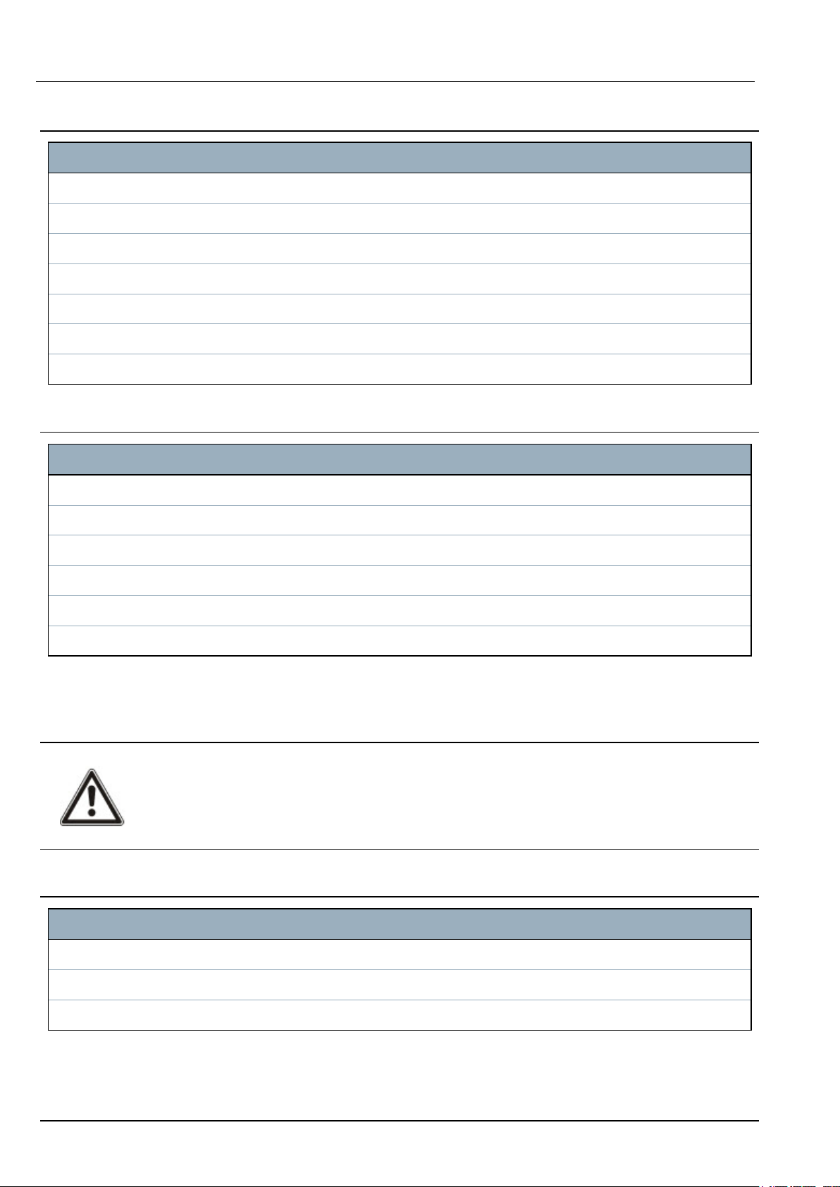
2.1 ACT365 VCU Connections
The ACT365 VCU requires an external 12V DC power supply connected to the +12V and 0V terminals on
the ACT365 VCU.
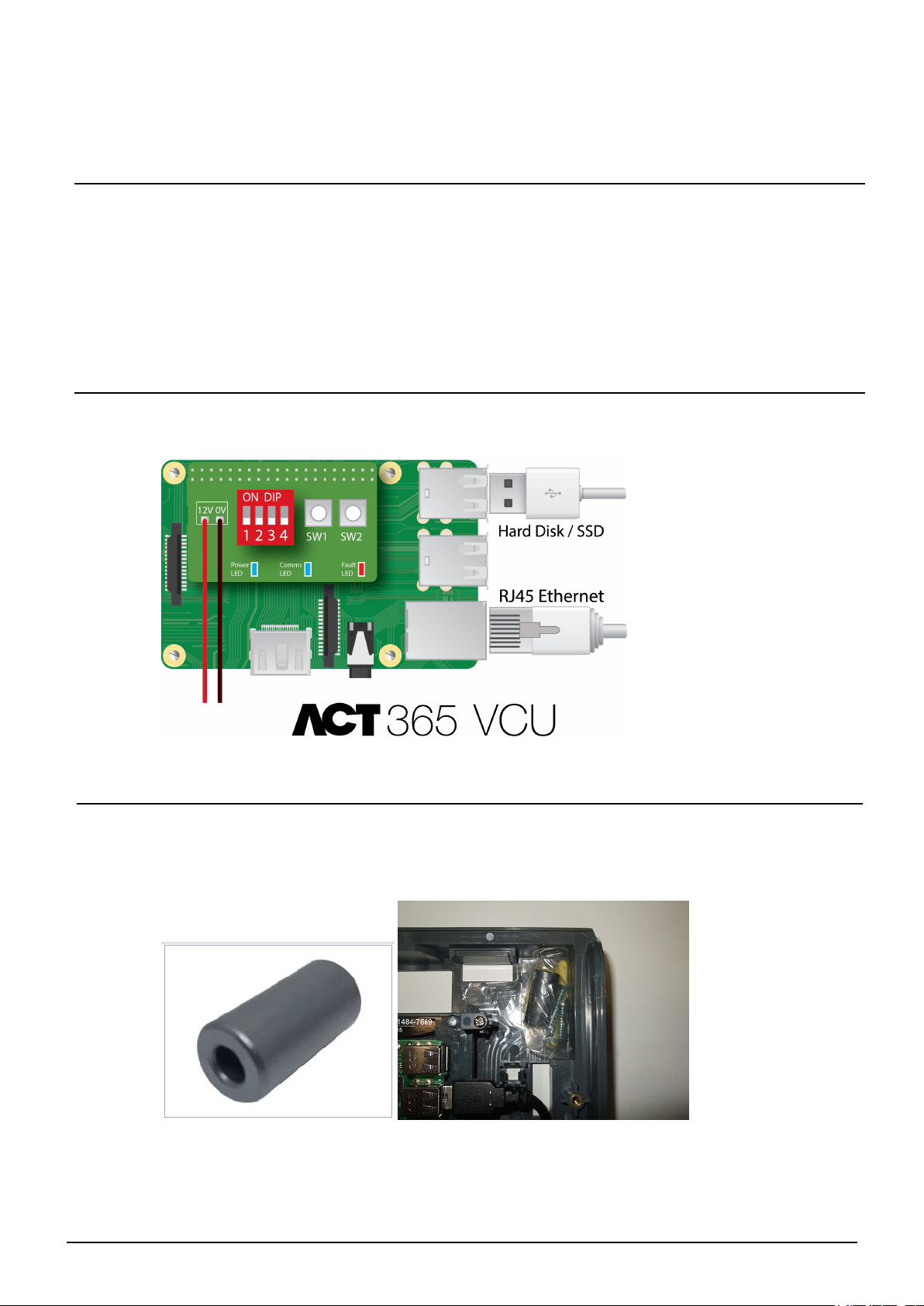
2.1.1 Ferrite bead installation
After you install the ACT365 VCU, Vanderbilt recommend that you place the provided ferrite bead (a noisesuppression device) around the Ethernet cable near the RJ45 connector to attain a desired level of
electromagnetic compatibility (EMC). The ferrite bead is provided along with a screw kit in a clear ziplock
bag inside the unit enclosure.
© Vanderbilt 2018 7 18-00103-b
06.07.2018
Page 8

ACT365 VCU – Installation and Operating Instructions Installing ACT365 VCU
Adding the ferrite bead to the Ethernet cable
1. Place the ferrite bead around the un-crimped Ethernet cable.
The ferrite bead should be positioned inside the enclosure, close to the RJ45 connector of the
ACT365 VCU unit, as shown below.
2. Once the ferrite bead is in place, crimp the Ethernet cable at the terminating end.
2.2 ACT365 VCU Status Indicators
Status indicators appear on the front of the ACT365 VCU.
The meaning of each indicator is described below.
(A) Power / System Running
This indicates that the ACT365 VCU has power.
(B) Communications
Constant illumination indicates that the VCU is connected to the ACT365 server.
Flashing indicates there is an issue connecting to the ACT365 server.
(C) Fault
Illuminates to indicate a fault on the VCU.
Possible causes are:
l Ethernet was connected after power up.
l The ACT365 VCU cannot connect to the ACT365 server.
l A low power condition was detected.
© Vanderbilt 2018 8 18-00103-b
06.07.2018
Page 9

ACT365 VCU – Installation and Operating Instructions Installing ACT365 VCU
2.3 Connecting ACT365 VCUs to a Customer LAN
Each ACT365 VCU can be connected directly to the customer network.
2.3.1 Cabling Chart
From To Network Type Cable Type Comments
LAN ACT365 VCU TCP/IP Cat5/6 Max distance between network devices is 100m.
© Vanderbilt 2018 9 18-00103-b
06.07.2018
Page 10

3 Configuring ACT365 VCU
This section describes:
3.1 Accessing the ACT365 VCU web interface 10
3.2 Adding Cameras using Discovery 11
3.3 Adding Cameras Manually 13
3.4 Installing ACT365 VCU on the ACT365 Installer Portal 15
3.5 Associating cameras to doors 16
3.6 Network Settings on ACT365 VCU 16
3.6.1 Reset the VCU hardware to use DHCP 18
3.7 Stream Settings on ACT365 VCU 18
3.8 Factory Reset 19
3.1 Accessing the ACT365 VCU web interface
The VCU web interface runs on port 8040 of the VCU.
To access the VCU web interface:
1. In your preferred web browser, enter http://{NetBIOS name}:8040 (NetBIOS name is printed on the
label on the PCB), or http://{IP address}:8040.
The VCU home page may take up to a minute to load.
If you do not know the VCU NetBIOS name or IP address, see How do I find the address of the
ACT365VCU? on page 24.
2. Enter the password and click Login.
The default password is 999999.
3. If this is the first time you have logged in, you are prompted to change the password. Enter a new
password and click Change.
© Vanderbilt 2018 10 18-00103-b
06.07.2018
Page 11

ACT365 VCU – Installation and Operating Instructions Configuring ACT365 VCU
This enforced password change is best practise to ensure the service stays
secure. If you lose your password, perform a factory reset of the unit (see Factory
Reset on page 19). Note that resetting the unit will remove any settings, cameras
and previous recordings.
Once the password is successfully changed, you may continue with the setup of VCU.
3.2 Adding Cameras using Discovery
To add a camera using discovery, log in to the ACT365 VCU web interface (see Accessing the ACT365
VCU web interface on the previous page), then:
1. Click the Cameras tab.
Automatically discovered cameras are listed in the Discovered Cameras section.
2. Select a camera in the Discovered Cameras list, then click Add.
The Probe Device dialog box displays.
© Vanderbilt 2018 11 18-00103-b
06.07.2018
Page 12

ACT365 VCU – Installation and Operating Instructions Configuring ACT365 VCU
3. (Optional) If the camera has a custom username and/or password, enter these custom details
into the Username and Password fields provided.
4. Click Probe.
When the probe has finished, a camera snapshot displays.
5. Enter an appropriate Name for the camera.
Vanderbilt recommend using a name that describes the camera location, for example, Front
Door.
© Vanderbilt 2018 12 18-00103-b
06.07.2018
Page 13

ACT365 VCU – Installation and Operating Instructions Configuring ACT365 VCU
6. Select the Record check box if the VCU should record camera footage. The VCU will record
approximately 20 days of camera footage (dependent on the type of scene the camera is viewing).
Once the VCU data storage limit is reached, data is recycled. When data is recycled, the oldest
data is removed first.
If you do not select Record, the VCU will support live view only.
7. Click Add.
The camera is added to the ACT365 Installer Portal at ACT365.eu.
A summary of the camera settings is displayed on the Cameras tab.
After a camera has been added, it appears in the Selected Cameras list and is accessible on ACT365.
3.3 Adding Cameras Manually
If a camera has not been discovered automatically, or is on a different IP subnet, you can add the camera
manually.
Notes:
l This can only be done locally on the VCU. This feature is not available on ACT365.
l Only expert users should manually add cameras. A camera stream URL must be entered
manually, and any inaccurate data entered could adversely affect the VCU operation.
To add a camera manually, log in to the ACT365 VCU web interface (see Accessing the ACT365 VCU
web interface on page 10), then:
1. Click the Cameras tab.
2. Click Add Manual.
The Probe Device dialog displays.
© Vanderbilt 2018 13 18-00103-b
06.07.2018
Page 14

ACT365 VCU – Installation and Operating Instructions Configuring ACT365 VCU
3. Enter the following details in the Probe Device dialog:
l Username: Camera login username
l Password: Camera login password
l IP: IP address of the camera, for example, 192.168.1.1.
l RTSP URL: Camera first stream URL, for example, rtsp://192.168.1.1/firststream.
l Snapshot URL: Camera snapshot URL, for example,
http://192.168.1.1/firststream/snapshot.
Camera URLs can be found on the manufacturer's websites or in the technical
documentation.
4. Click Probe.
When the probe has finished, a camera snapshot displays.
5. Enter an appropriate Name for the camera.
© Vanderbilt 2018 14 18-00103-b
06.07.2018
Page 15

ACT365 VCU – Installation and Operating Instructions Configuring ACT365 VCU
Vanderbilt recommend using a name that describes the camera location, for example, Front Door.
6. Select the Record check box if the VCU should record camera footage. The VCU will record
approximately 20 days of camera footage (dependent on the type of scene the camera is viewing).
Once the VCU data storage limit is reached, data is recycled. When data is recycled, the oldest
data is removed first.
If you do not select Record, the VCU will support live view only.
7. Click Add.
The camera is added to the ACT365 Installer Portal at ACT365.eu.
A summary of the camera settings is displayed on the Cameras tab.
After a camera has been added, the camera details appear in the Selected Cameras list and the camera is
accessible on ACT365.
3.4 Installing ACT365 VCU on the ACT365 Installer Portal
To add ACT365 VCU to a customer site on the ACT365 Installer Portal:
1. Log in to the ACT365 Installer Portal at ACT365.eu.
ACT365 is only available to registered installers. You can register at ACT365.eu.
2. Enter the customer portal from the ACT365 Installer Portal.
To do this:
a. Click Customers to open a list of customers.
b.
Click the Enter Customer Portal icon beside a customer name to enter the customer
portal.
3. Click Hardware > ACT365VCUs.
4. Click ADD ACT365 VCU.
5. Enter the ACT365 VCU details.
a. Enter the Controller Unique Identifier (CUID). This is printed on the label on the controller PCB.
© Vanderbilt 2018 15 18-00103-b
06.07.2018
Page 16

ACT365 VCU – Installation and Operating Instructions Configuring ACT365 VCU
b. Enter the name of the ACT365 VCU. Vanderbilt recommend that you enter a name that
describes the VCU location.
c. Select the site where the ACT365 VCU will be installed.
d. Click Save.
The ACT365 VCU is added to the customer site. A green tick mark appears in the
Connected column if the connection is successful.
6.
To verify the VCU status, select the diagnostics icon for the ACT365 VCU and select the
hyperlink for the VCU in the first panel.
See Diagnostics on ACT365 VCU on page 23 for information on VCU diagnostics.
See Configuring ACT365 VCU on page 10 for information on configuring cameras on ACT365
VCU.
3.5 Associating cameras to doors
Associating cameras to a door enables customers to view recorded footage. Log events for the footage
can be replayed from the Reports > Log Events menu.
1. Log in to the ACT365 Installer Portal at ACT365.eu.
2. Click Access Control > Doors.
3. Click the name of the door for which you wish to make the camera association.
4. In the Door Camera Associations panel, click the field to open a drop-down list from which you
can select the cameras to be associated with the door.
5. Click Save.
3.6 Network Settings on ACT365 VCU
The VCU is configured to use DHCP addressing by default. You can modify network settings through
the VCU web interface.
© Vanderbilt 2018 16 18-00103-b
06.07.2018
Page 17

ACT365 VCU – Installation and Operating Instructions Configuring ACT365 VCU
To configure the VCU to use a static IP address, log in to the ACT365 VCU web interface (see Accessing
the ACT365 VCU web interface on page 10), then:
1. Click the Network Settings tab.
2. Under Static IP Settings, set the required addresses for Gateway, IP Address and Subnet Mask.
3. Click Apply to save changes.
The unit reboots. After reboot, the new IP address is in effect.
To configure the VCU to use DHCP addressing, log in to the ACT365 VCU web interface (see Accessing
the ACT365 VCU web interface on page 10), then:
1. Click the Network Settings tab.
2. Under Static IP Settings, delete values for Gateway, IP Address and Subnet Mask.
3. Click Apply to save changes.
The unit reboots. After reboot, DHCP addressing is in effect.
You can optionally enter a Site Name and VCU Description in the VCU Information section on the
Network Settings tab. This information helps to identify the units and may assist Vanderbilt support if
you need help.
© Vanderbilt 2018 17 18-00103-b
06.07.2018
Page 18

ACT365 VCU – Installation and Operating Instructions Configuring ACT365 VCU
3.6.1 Reset the VCU hardware to use DHCP
If a VCU has an invalid IP address, or the unit is no longer accessible on its known IP address, the red
LED will flash on unit boot. You can reset the VCU to use DHCP using the following procedure:
1. Set the DIP switches as follows:
When the blue lights start to flash, this indicates that the IP reset is complete.
2. Set the all DIP switches to OFF.
The unit reboots automatically.
After reboot, the unit is back on DHCP.
3.7 Stream Settings on ACT365 VCU
Video quality can be configured from the Stream Settings tab in the ACT365 VCU web interface. The
settings apply to all cameras connected to the VCU. If a particular camera does not support the
selected values, the next available values will be used instead on that camera.
To configure stream settings, log in to the ACT365 VCU web interface (see Accessing the ACT365
VCU web interface on page 10), then:
1. Click the Stream Settings tab.
2. Select one of the following options:
l Standard stream profile (default setting: 720p, H264, 25fps, 1024 Kbps)
l High stream profile (1080p, H264, 25fps, 2048 Kbps)
l Manual stream profile. This profile option is only recommended for experienced camera
installers. Customize this streaming profile by editing the Values. Ensure that your manual
© Vanderbilt 2018 18 18-00103-b
06.07.2018
Page 19

ACT365 VCU – Installation and Operating Instructions Configuring ACT365 VCU
settings are supported by your connection bandwidth.
3.8 Factory Reset
In the event of a unit failure or forgotten VCU password, follow the procedure below to factory reset the
VCU.
IMPORTANT: Factory reset removes all custom settings and camera databases. Previous camera
footage is erased. Factory reset is NOT REVERSIBLE and should only be used as a last resort.
You can also perform a factory reset from the VCU web interface Diagnostics tab. See Diagnostics
on ACT365 VCU on page 23 for more information.
1. Power off the VCU.
2. Configure the unit DIP switches as pictured below. (ON = 2,4; OFF = 1,3)
3. Power up the VCU. Wait for the red LED to flash.
4. Reset all DIP switches to the OFF position, as pictured below. (OFF = 1, 2, 3, 4)
5. The LEDs will turn off and the unit will reboot.
The VCU is now defaulted to factory settings.
© Vanderbilt 2018 19 18-00103-b
06.07.2018
Page 20

4 Video
This section describes:
4.1 Viewing Live Video on the ACT365 VCU 20
4.2 Viewing Live Video on the ACT365 Installer Portal 21
4.3 Viewing recorded footage on the ACT365 Installer Portal 21
4.4 Exporting Video from the ACT365 VCU 22
4.1 Viewing Live Video on the ACT365 VCU
To view a live video stream from the ACT365 VCU, log in to the ACT365 VCU web interface (see
Accessing the ACT365 VCU web interface on page 10), then:
1. Click the Live tab.
2. Click the play button in the centre of any camera feed. The stream may take a few seconds to
buffer.
© Vanderbilt 2018 20 18-00103-b
To display additional diagnostic information overlaid on the camera stream, select the Diagnostics
check box at the bottom of the screen before viewing the required live video stream.
06.07.2018
Page 21

ACT365 VCU – Installation and Operating Instructions Video
4.2 Viewing Live Video on the ACT365 Installer Portal
To view a live video stream from the ACT365 Installer Portal:
1. Log in to the ACT365 Installer Portal at ACT365.eu.
2. Enter the customer portal from the ACT365 Installer Portal.
To do this:
a. Click Customers to open a list of customers.
b.
Click the Enter Customer Portal icon beside a customer name to enter the customer
portal.
3. Click Video > Live View.
4. (Optional) Select a camera.
5. Click the play button in the centre of the camera feed.
The stream may take a few seconds to buffer.
4.3 Viewing recorded footage on the ACT365 Installer Portal
To view recorded footage on the Installer Portal:
1. Log in to the ACT365 Installer Portal at ACT365.eu.
2. Enter the customer portal from the ACT365 Installer Portal.
To do this:
a. Click Customers to open a list of customers.
b.
Click the Enter Customer Portal icon beside a customer name to enter the customer
portal.
3. Click Video > Video Footage.
4. Select the camera(s) for which you want to view footage.
The timeline at the bottom of the screen is populated with available recordings for the selected
camera(s).
5. Select the Show Access Control Events check box above the timeline.
© Vanderbilt 2018 21 18-00103-b
06.07.2018
Page 22

ACT365 VCU – Installation and Operating Instructions Video
6. Click an access control event icon or click a specific time point on the time bar to view footage
from the selected camera(s) at that time.
4.4 Exporting Video from the ACT365 VCU
Footage can be exported locally on the VCU via the export tap in the local web access.
Exporting locally saves bandwidth and resources, as footage does not need to be uploaded to the
cloud to be prepared before export.
To export video from the VCU, log in to the ACT365 VCU web interface (see Accessing the ACT365
VCU web interface on page 10), then:
1. Click the Export tab.
2. Select a camera from the Camera drop-down menu.
3. Select a date and time range for the export.
4. Click Export.
The ACT365 VCU converts and exports the selected footage. When this process is complete,
the new video file is downloaded in accordance with your browser download settings.
© Vanderbilt 2018 22 18-00103-b
06.07.2018
Page 23

5 Diagnostics on ACT365 VCU
Log in to the ACT365 VCU web interface (see Accessing the ACT365 VCU web interface on page 10) and
click the Diagnostics tab.
From this tab, you can view the VCU Status, the Camera Status for each camera that is connected to the
VCU, and the VCU Event Log.
You can also perform the following VCU maintenance tasks:
l Reboot the VCU. Click Reboot to shut down services and reboot the VCU.
l Reset the VCU to factory defaults. Click Factory Reset to remove all local configuration and
reset the unit. You can also reset the VCU as described in Factory Reset on page 19.
l Identify an individual VCU. Click ID Mode and all LEDs on the VCU will flash repeatedly. Click
again to resume normal operation.
l Enable automatic firmware updates. By default, automatic updates are turned off. If new
firmware is available, the update must be initiated from the ACT365 Installer Portal. To enable
automatic firmware updates, select the AutoUpdate check box.
l Set a unique password for the VCU. Enter a new password in the field provided and click Set
Password.
© Vanderbilt 2018 23 18-00103-b
06.07.2018
Page 24

6 FAQs
This section covers the following:
6.1 How do I find the address of the ACT365VCU? 24
6.2 What is the password for the VCU web front end? 25
6.3 Why is the VCU not connecting to ACT365? 25
6.4 How many cameras can I add to my VCU? 26
6.5 Why can I not see my cameras on the camera setup page? 26
6.6 Why can I not log in to ACT365 VCU with Internet Explorer 11? 26
6.7 What are the bandwidth requirements for the VCU? 26
6.8 Why can’t I access the VCU web server? 27
6.9 What browsers are supported for video playback on ACT365? 27
6.10 Where can I get the latest Adobe Flash Player? 27
6.11 What IP cameras does the VCU support? 27
6.12 Does the VCU support camera recording? 28
6.13 Why is my camera feed not working on Windows 7/IE11? 28
6.1 How do I find the address of the ACT365VCU?
To find the NetBIOS name or IP address of the VCU, do one of the following:
l Use Windows Explorer on your PC to find the IP address of the VCU under the Network folder.
Navigate to the Network folder in Windows Explorer and double-click the VCU. This will take you
directly to the VCU home page.
l Download the VCU Discovery Tool from the Installer Utilities page of the ACT365 Installer Portal.
Run the tool to scan the network for the VCU. Double-click the required VCU in the list of
discovered VCUs.
© Vanderbilt 2018 24 18-00103-b
06.07.2018
Page 25

ACT365 VCU – Installation and Operating Instructions FAQs
6.2 What is the password for the VCU web front end?
The default password is 999999. After first login, you are prompted to change the password. The password
can also be changed on the Diagnostics page on the ACT365 VCU (see Diagnostics on ACT365 VCU on
page 23). Ensure that the password is keep safe once set.
If you forget your password, a factory reset may be required to gain access to the unit. See Factory Reset
on page 19 for more information.
6.3 Why is the VCU not connecting to ACT365?
While operating, the ACT365 VCU must connect to https://api.act365.eu on port 443.
If the ACT365 VCU is not connecting:
1. Check that the LEDs on the ACT365 VCU Ethernet jack are active.
If no LEDs are illuminated, then check the Ethernet cable is inserted fully and is connected to a live
Ethernet port.
2. Ping the ACT365 VCU using either the NetBIOS name or IP address and ensure the controller
responds.
NetBIOS name example: ping ACT365VCU010049
IP address example: ping 192.168.1.60
3. If the ping fails, ensure that the ACT365 VCU IP address is set:
l If the VCU is set to use DHCP, ensure that the DHCP server on your network is running.
l If the VCU is set to use a static IP address, ensure that the address is set correctly.
4. If the ping is successful:
a. Log in to the ACT365 VCU web interface (see Accessing the ACT365 VCU web interface on
page 10).
b. Click the Diagnostic tab.
c. Check that all entries under VCU Status show a status of OK.
5. Log in to the ACT365 Installer Portal at ACT365.eu and check that the ACT365 VCU CUID
matches what is printed on the label inside the controller.
If the problem is not resolved, contact the customer IT department as there may be a problem with the
customer network.
© Vanderbilt 2018 25 18-00103-b
06.07.2018
Page 26

ACT365 VCU – Installation and Operating Instructions FAQs
6.4 How many cameras can I add to my VCU?
The VCU can support up to 4 cameras per unit. Multiple VCUs can be added to the same site.
6.5 Why can I not see my cameras on the camera setup page?
The ACT365 VCU automatically discovers cameras on the network. If ACT365 VCU fails to discover
any cameras, check the following:
l Does the camera have connectivity?
l Does the VCU have connectivity?
l Are cameras fully up to date with latest manufacturer firmware?
l Are the VCU and cameras connected on the same network/network IP range?
l Are cameras compliant with ONVIF 2.0 Profile S or later?
6.6 Why can I not log in to ACT365 VCU with Internet Explorer 11?
Internet Explorer 11 may restrict viewing of ACT365 web pages due to compatibility configuration.
To resolve this issue:
1. In Internet Explorer 11, click Tools > Compatibilty View Settings.
2. De-select the Display Intranet sites in Compatibility View check box and click Close.
6.7 What are the bandwidth requirements for the VCU?
The VCU can support up to 4 cameras.
Maximum and minimum upload bandwidth requirements for concurrent viewing at Standard stream
settings (1Mbps per camera) are:
l Maximum: 8 Mbps upload, 8 Mbps download (4 live, 4 replay)
l Minimum: 1 Mbps upload or download (1 live or replay)
If unsure of upload/download speed capabilites, contact the network administrator or perform a speed
test using a service such as speedtest.net. Note that a speed test provides a snapshot of the network
© Vanderbilt 2018 26 18-00103-b
06.07.2018
Page 27

ACT365 VCU – Installation and Operating Instructions FAQs
performance at the time of the test; network performance will vary over time and may degrade with
increasing demands.
6.8 Why can’t I access the VCU web server?
In ACT365, ensure that Enable Local Web Server is set under Hardware > ACT365 VCUs.
6.9 What browsers are supported for video playback on ACT365?
Tested and supported internet browsers are listed in the following table.
Operating
system
Windows 7 l Internet Explorer 11 or higher with latest Adobe Flash Player (only IE 11 on Windows 7 needs
Windows 10 OS l Google Chrome
Mac OS X l Google Chrome
Browser(s)
an Adobe Flash Player plugin enabled)
l Google Chrome
l Mozilla Firefox
l Opera
For the best user experience, Vanderbilt recommend using Google Chrome or Mozilla Firefox.
l Mozilla Firefox
l Opera
l Microsoft Edge
For the best user experience, Vanderbilt recommend using Google Chrome, Microsoft Edge or
Mozilla Firefox.
l Mozilla Firefox
l Opera
l Safari
Linux l Google Chrome
l Mozilla Firefox
l Opera
iOS Safari
Android Chrome
You should ensure that all browsers are up to date for best performance.
6.10 Where can I get the latest Adobe Flash Player?
You can download Adobe Flash Player from https://get.adobe.com/flashplayer.
6.11 What IP cameras does the VCU support?
The VCU is compatible with most ONVIF 2.0 profile S or later IP cameras. Ensure that your camera meets
this specification. For more information regarding ONVIF or supported cameras visit: www.onvif.org
© Vanderbilt 2018 27 18-00103-b
06.07.2018
Page 28

ACT365 VCU – Installation and Operating Instructions FAQs
6.12 Does the VCU support camera recording?
Yes. The VCU ships with a 1TB SATA disk for recording storage. This enables the VCU to record each
camera. The VCU automatically allocates 250GB per channel for recordings.
6.13 Why is my camera feed not working on Windows 7/IE11?
IE has a cache which can cause playback issues using Adobe Flash Player.
1. Run Internet Explorer.
2. Click Tools > Internet Options.
3. Under Browsing History click Settings.
4. On the Temporary Internet Files tab, under Check for newer versions of stored pages
select Every time I visit the web page.
5. Click OK.
6. Click OK.
© Vanderbilt 2018 28 18-00103-b
06.07.2018
Page 29

vanderbiltindustries.com
© Vanderbilt 2018
Data and design subject to change without notice.
Supply subject to availability.
Document ID: 18-00103-b
Edition date: 06.07.2018
Issued by Vanderbilt International Ltd.
Clonshaugh Business and Technology Park
Clonshaugh, Dublin D17 KV 84, Ireland
@VanderbiltInd Vanderbilt Industries
vanderbiltindustries.com/contact
 Loading...