

Page 1

FEDERAL COMMUNICATIONS COMMISSION (FCC) STATEMENT
This equipment has been tested and found to comply with the limits for a Class B
digital device, pursuant to Part 15 of the FCC Rules. These limits are designed to
provide reasonable protection against harmful interference in a residential
installation. This equipment generates, uses and can radiate radio frequency
energy and, if not installed and used in accordance with the instructions, may
cause harmful interference to radio communications. However, there is no
guarantee that interference will not occur in a particular installation. If this
equipment does cause harmful interference to radio or television reception, which
can be determined by turning the equipment off and on, the user is encouraged to
try to correct the interference by one or more of the following measures:
• Reorient or relocate the receiving antenna.
• Increase the separation between the equipment and receiver.
• Connect the equipment into an outlet on a circuit different from that to which the
receiver is connected.
• Consult the dealer or an experienced radio/TV technician for help.
CAUTION: Changes or modifications not expressly approved by the manufacturer
responsible for compliance could void the user’s authority to operate the
equipment.
TRADEMARKS
Intel and Pentium are registered trademarks of Intel Corporation.
Microsoft and Windows are registered trademarks of Microsoft Corporation. DOS,
Windows 95/98/ME/ 2000/NT/XP are trademarks of Microsoft Corporation.
All other brand names mentioned in this manual are trademarks and/or registered
trademarks of their respective owners/companies.
Page 2

WARNING AND DISCLAIMER
This manual is designed to provide information about the product. Efforts have
been made to make this manual as accurate as possible, but no warranty of fitness
is implied. All the information is provided on an “as is” basis. The author and his
corresponding publishing company shall have neither liability nor responsibility to
any person or entity with respect to any loss or damages arising from the
information contained in this manual or from the use of the product that
accompanies it.
Information contained in this manual is subject to change without notice. The
manufacturer of the product will not be held responsible for technical or editorial
omissions made herein, nor for the incidental or consequential damages resulting
from its furnishing, performance, functionality or use. Subsequent changes to this
manual will be incorporated into the next edition. We welcome any suggestion
regarding this manual and product.
COPYRIGHT
Copyright 2006© by this company. The information in this user’s manual is
protected by copyright laws. No part of this manual may be photocopied or
reproduced in any form without prior written authorization from the copyright
owners. All rights reserved.
Manual Version: 2.0
Release Date: Jan. 2006
Page 3

Important Safeguard
Safety Instruction
1. Read Instructions — All the safety and operation instructions should be read
before operating the system
2. Retain Instructions — The safety and operating instructions should be retained
for future reference.
3. Heed Warnings — All warnings on the appliance and in the operating
instructions should be heeded.
4. Follow Instructions — All operation and usage guide should be followed
5. Use only attachments recommended by the manufacturer; unapproved
attachments may cause hazards.
6. Subject the system on an even and stable surface. Do not place it on an
unstable cart, stand, table, any rocky surfaces, and shaky or vibrating place.
The system may fall, causing serious injury to a child or adult, and serious
damage to the system
7. Any mounting of the system product should follow the manufacturer’s
instructions, and should use a mounting accessory recommended by the
manufacturer
8. Do not place the system product on fabric cotton materials such as bed, sofa,
rug, blanket or similar surface.
9. Do not place the system product in a bookcase or cabinet unless proper
ventilation is provided.
10. Do not expose the system to moisture, water or rain.
11. Keep the system away from dirt, dust, water or other liquid.
12. Ventilation — Slots and openings in the cabinet are provided for ventilation to
ensure reliable operation of the system, and to protect it from overheating.
These openings must not be blocked or covered. Do not lean the system direct
to the wall. Keep some spaces (min. 5 cm) between the wall and system
product.
13. Do not push any object into the slot in the system product cabinet. It could touch
dangerous voltage points or short out parts resulting in a fire or electric shock.
14. Keep the system and power supply away from direct sunlight or any source of
heat. Do not subject the system to the temperature below 0
o
C (32oF) or above
40
o
C (104oF). Do not place the system product near or over a radiator or heat
register.
15. Keep the system product away from the magnetic interference such as high
capacity transformers, electric motors, television, and other strong magnetic
objects.
16. Do not place the computer on the top of the other electronic devices.
17. Do not place heavy objects on top of the computers.
18. To protect the system product during a lightening storm or when it is left
unattended and unused for long periods of time, unplug it from the wall outlet.
This will prevent damage to the system product due to lightning and power-line
surges.
Page 4

Important Safeguard
19. Unplug the power cord before inserting any add-on card or module.
20. Use power cord correctly. There are some important safety requirements.
The power cord is equipped either a 2-prong or a 3-prong grounded plug.
The third prong is an important safety feature; do not defeat the safety
purpose of the third grounded plug. If your outlet does not accommodate
the plug, have a qualified electrician install the correct outlet, or use an
adapter to ground the system product safely.
Do not leave the power cord where people may walk on it or place heavy
objects on top of it.
Do not overload wall outlet and extension cords. Electric power overload
will cause fire or electric shock.
When unplug the power cord, be sure to disconnect it by the plug head,
not by its wire.
Keep the power cord/adapter away from children.
Cleaning
1. Unplug the power cord from the wall outlet before cleaning the system
2. Do not use liquid or aerosol cleaner.
3. Use a damp cloth for cleaning.
Servicing
1. Do not attempt to service this system product yourself. Opening covers or
removing components may ruin your warranty and expose you to dangerous
voltage or other electric hazards. Refer all servicing to qualified service
personnel.
2. Damage Requiring Service— Unplug this system from the wall outlet and refer
servicing to qualified service personnel under the following conditions:
When the power cord or plug is damaged or frayed.
If liquid has been spilled or objects have fallen into the system product
If the system product has been exposed to rain or water
If the system product has been dropped or damaged.
The computer does not work normally after you follow the operating
instructions.
3. Replacement Parts — When replacement parts are required, be sure the
service technician has used replacement parts specified by the manufacturer
or which have the same characteristics as the original parts. Unauthorized
substitutions may result in fire, electric shock, or other hazards.
Page 5

TABLE OF CONTENTS
I. Introduction 1
1-1 Product Specifications 1
1-2 Package Contents 2
II. Product Overview 3
2-1. Front View 3
2-2. Rear View 4
2-3. Right side View 5
2-4. Left side View 6
2-5. Bottom View 7
2-6. System Layout 9
2-7. Chassis 10
III. Hardware Installation 11
3-1. Prepare to Install 11
3-1-1 Installation Tools 11
3-1-2 Packing Checklist for Installation 11
3-2. Installation Flowchart 12
3-3. Installation Procedures 13
3-3-1 Remove Back Chassis Cover 13
3-3-2 Mount the Hard Disk Drive 14
3-3-3 Mount the Mainboard 14
3-3-4 Connect Mainboard Audio Cables 15
3-3-4 Connect All other Cables 16
3-3-5 Install the Riser Cards 17
3-3-6 Connect VGA Cable 20
3-3-7 Finish the installation 20
IV. LCD Panel Monitor 21
4-1. LCD Panel Monitor Specifications 21
4-2. Activate the Monitor 22
4-3. Adjust the Monitor 22
4-3-1 Monitor Control Keys 22
4-3-2 Display Adjustment 23
V. Troubleshooting 30
Page 6

- 1 -
I Introduction
1-1 Product Specifications
Followed by the intelligent "Easy Assemble” system design, this LCD PC barebone
can be easily configured by the desktop PC components. It gives users the
freedom to install the standard P4 mATX mainboard into an all-in-one LCD PC in
seconds. All the necessary components can be found in the market which
tremendously reduces the troubles of repairing or upgrading. Also, it's unique PCI,
AGP and PCI-E riser cards provide system the extension flexibility.
Moreover, to connect PC to the consumer electronics world, this LCD PC barebone
provides the function of playing TV, DVD, Video, internet game, Hi-Fi audio and
much more by equipping the SXGA LCD Panel, slim optical drive, latest card
reader and powerful output speakers. Other considerate designs include the
aluminum chassis which keeps high specification systems in a heat-free
environment; the tilt, VESA and optional touch panel provide users the various
application possibility. The LCD PC barebone’s specifications are following.
Mainboard Standard mATX mainboard
LCD Display 17"/19” SXGA TFT LCD Panel,1280 pixel (H) x 1024 pixel (V)
Hard Disk Drive 3.5" standard type
Optical Drive Exchangeable slim optical drive.
Extensional Slot AGP/ PCI / PCI Express slot
Speaker 2 X 5W build-in speakers.
Card Reader Multi-in-one card reader
Power 220W Power Supply w/PFC. AC Input Voltage: 100 - 127V ~/5A 60
Hz; 200–240V ~/3A 50 Hz; Manual select switch
Physical Dimension 17”: 540(W)X330(H)X125(D) mm. (415mm height w/base)
19”: 570(W)X360(H)X125(D) mm. (445mm height w/base)
Weight 17”: N.W.: 9.2 KG G.W.: 11 KG
19”: N.W.: 9.8 KG G.W.: 11.8 KG
Tilt 15∘up and 3∘down
Touch Panel Optional
Wall Mount Standard 10 cm VESA
Safety Regulations CE, FCC, UL
Page 7

- 2 -
I Introduction
1-2 Package Contents
Power Cord
User Manual
LCD PC Barebone
AGP Riser Card
PCI-E Riser Card
PCI Riser Card
Screws
Note:
These pictures are for reference only, and may not reflect the exact contents of the package.
After removing the barebone system from the package, check to see if there is anything
visibly wrong with it. Contact your local dealer for further package information if having any
doubts.
Page 8
- 3 -
II Product Overview
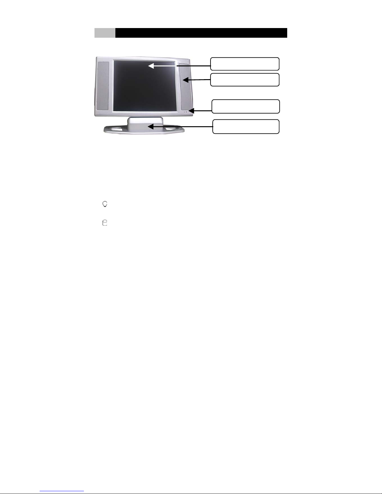
2-1 Front View
(1) LCD Display Panel
(4) Tilt Stand
(2) Build-in Speaker
(3) LED Indicator
(1) LCD Display Panel
This system product equipped the 17 / 19 inches liquid crystal display with SXGA
standard.
(2) Build-in Speaker
The two 5W build-in speakers on two sides output powerful stereo sound.
(3) LED Status Indicators
Power Indicator: Indicate the system status. Blue lights up when the power is
ON.
HDD Indicator: Indicate the HDD status. Yellow lights up when the HDD is
working.
(4) Tilt Stand
The stand makes 15∘up and 3∘down adjustable tilt directions.
Page 9

- 4 -
II Product Overview
2-2 Rear View
(1)
VESA Wall Mount Hole
(2)
Ventilation Openings
(3)
2 x USB 2.0 Ports
(4)
Line-out / Mic-in Jack
(5)
Drawable sub-stand
(1) VESA Wall Mount Hole
The holes for standard 10cm VESA wall mount keep the system mount on the wall
easily and firmly.
(2) Ventilation Openings
Slots and openings in the cabinet are provided for ventilation to ensure reliable
operation of the system, and to protect it from overheating.
(3) USB 2.0 Ports
The two 4-pin Universal Serial Bus (USB) ports can connect a wide variety of
devices via the USB cable and each port is able to connect up to 128 devices via
USB hubs. The two USB ports conform to USB 2.0 and plug-and-play standards.
(4) Line-Out / Mic-in Jack
The Line-out jack is to connect the headphones or external speakers.
When using external speakers, disable the internal built-in speakers first.
The Mic-In jack is to connect the microphone.
(5) Drawable Sub-stand
The drawable Sub-stand can be pull out to enforce the stability of the stand.
Page 10
- 5 -
II Product Overview
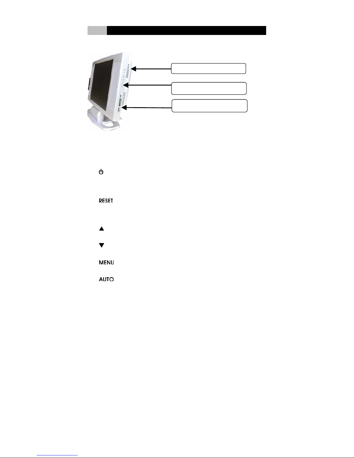
2-3 Right Side View
(2) Function Keys
(1)
Ventilation Openings
(3) Multi-in-One Card Reader
(1) Ventilation Openings
Slots and openings in the cabinet are provided for ventilation to ensure reliable
operation of the system, and to protect it from overheating.
(2) Function Keys
1. Power Key:
Turn the System and LCD Panel on or off. This system uses a special
one-button design. Press it to turn on the system and panel. Press momentarily
again to turn off the system and panel.
2.
Hardware Reset Key:
To reset the system in case it hangs.
Monitor Control Keys:
3.
Up key:
Make cursor moves up to switch the previous function in sequence.
4.
Down key:
Make cursor moves down to switch the previous function in sequence.
5.
Menu key:
Enter main-menu and sub-menu.
6.
Auto key:
Adjust vertical position, phase, and horizontal position and pixel clock
automatically.
Page 11

- 6 -
II Product Overview
Note:
Please refer to Chapter IV LCD Panel Monitor for more information of functional control.
(3) Multi-in-One Card Reader
This card reader is multi-in-one type includes 1x USB port, 1x Compact Flash, 1x
Memory Stick, 1x Smart Media, and 1x Secure Digital slots.
It supports USB Revision 2.0, Compact Flash I / II, IBM Micro drive, Smart media,
Secure Digital, Mini SD, Multi Media Card, RS-MMC, Memory Stick, MS-Pro,
MS-Duo, MS-Pro Duo, MS-magic Gate, excellent Digital.
The card reader is automatic card detection. It supports hot swapping between
cards and copying among different media or cards.
2-4 Left Side View
(1) Optical Device Bay
This is where the CD-ROM, DVD-ROM, CD-R/RW, CD-R/RW/DVD Combo,
DVD-R/RW/DVD combo drive was fixed to.
The optical drive (optional CD-ROM, DVD-ROM, CD-R/RW, CD-R/RW / DVD
Combo, DVD-R/RW / DVD combo) is a slim internal type, weight 235 +/- 5 g for
steel or 190 +/- 5g aluminum top case; designed by internal drawer type manual
load structure with 12.7 mm height. The IDE/ATAPI interface enables to access
various CD/DVD formats widely. It supports multi-operating systems.
(1) Optical Device Bay
Page 12
- 7 -
II Product Overview
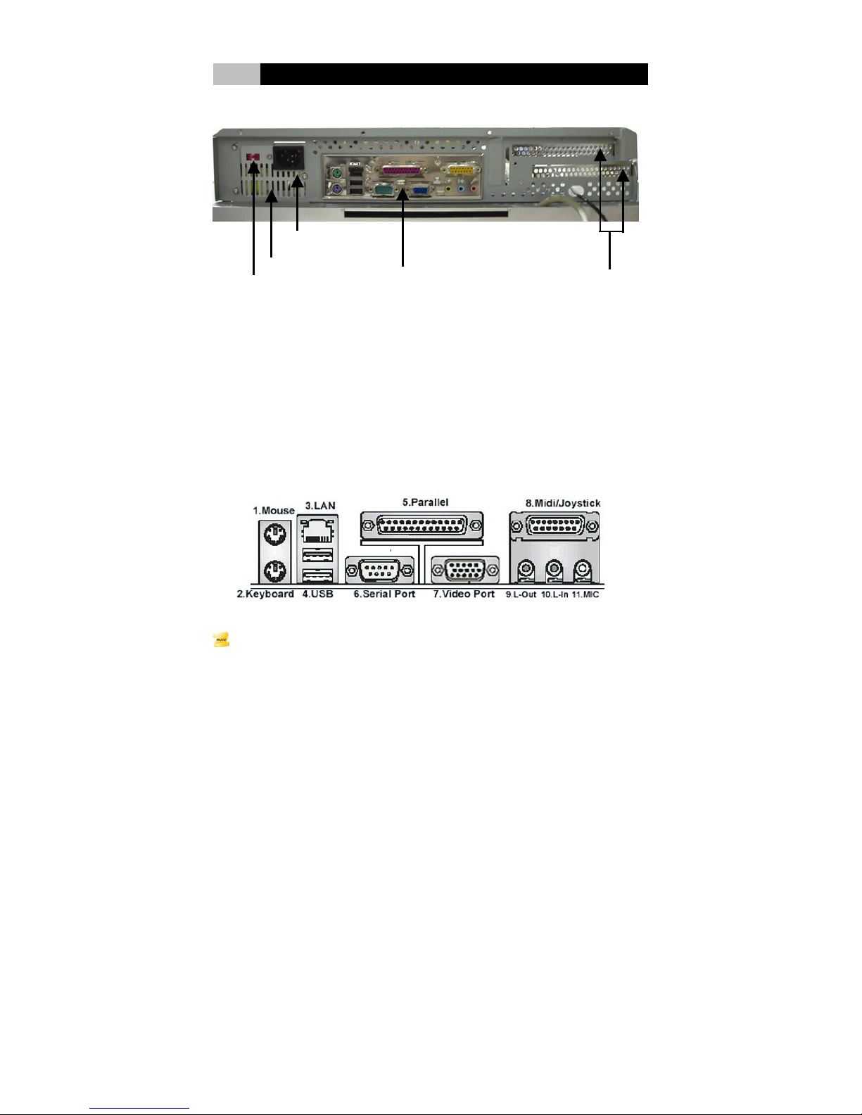
2-5 Bottom View
(3)
Power Socket
(1) Voltage Switch
(2) Fan Grill
(4) Mainboard I/O Ports
(5) Extension Brackets
(1) Voltage Switch
The manual select switch needs to be adjusted based on the different AC Input.
AC Input Voltage: 100 - 127V ~/5A 60 Hz; 200 - 240V ~/3A 50 Hz.
(2) Fan Grill
The fan grill is where hot air is expended. This airway must not be blocked or covered
.
(3) Power Socket
This is where the AC power cord connected to the system.
(4) Mainboard I/O Ports
Note:
This mainboard I/O guide is for reference only and may not be exact representation of the
I/O configuration and layout for your system. Please refer to the user’s manual provided by
your mainboard vendor for the detailed information.
Page 13

- 8 -
II Product Overview
1. PS/2 Mouse Port
The green 6-pin mini DIN connector is to connect a PS/2 mouse.
2. PS/2 Keyboard Port
The purple 6-pin mini DIN connector is to connect a PS/2 Keyboard.
3. LAN Jack
The RJ-45 jack conforms to 10Base-T and 100Base-TX transmission
protocols and can connect to Local Area Network (LAN).
4. USB 2.0 Ports
The two 4-pin Universal Serial Bus (USB) ports can connect a wide variety of
devices via the USB cable and each port is able to connect up to 128 devices via
USB hubs. The two USB ports conform to USB 2.0 and plug-and-play standards.
5. Parallel Port
The 25-hole parallel port is a standard printer port that supports Enhanced
Parallel Port (EPP) and Extended Capabilities Parallel Port (ECP) mode. It
primarily
connects to a parallel printer, scanner or other devices.
6. Serial Port
The 9-pin COM1 port is for pointing devices or other serial devices through
a 9-pin serial (RS-232) cable.
7. Video Port
The VGA DB 15 Pin Connector is to connect a VGA monitor or other
VGA-compatible devices.
8. Midi / Joystick Port
The 16-pin game port is to connect a game pad or joystick.
9. L-Out Jack
The Line-out jack is to connect the headphones or external speakers. When
using external speakers, the internal built-in speakers need to be disabled.
10. L-In Jack
The Line-in jack is to connect the external CD player, Tape player, or other
audio devices. It was disabled if the build-in L-in jack on the rear of the
system has activated.
11. Mic jack
The Microphone input jack is to connect a microphone. It was disabled if the
build-in Mic-in jack on the rear of the system has activated.
Page 14
- 9 -
II Product Overview
(5) Extension Brackets
The two brackets are where the extension cards were fixed to.
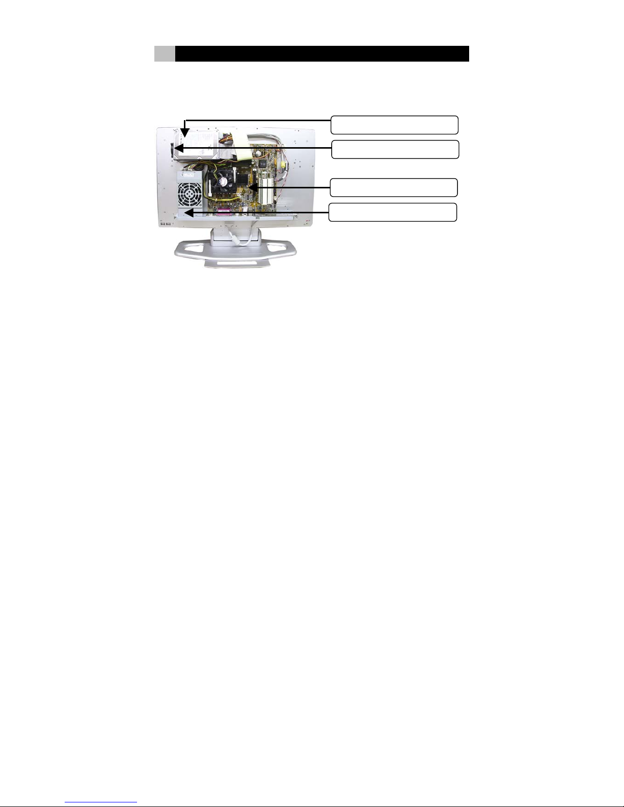
2-6 System Structure
(1)
Hard Disk Drive
(3)
Mainboard
(2) Sy
stem Fan
(4)
Power Suppl
y
(1) Hard Disk Drive
The Hard Disk Drive is 3.5” Height, ATA-33/66/100 Ultra DMA desktop PC type.
(2) System Fan
The System Fan is a 5
cm, 3000 spin fan.
(3) Mainboard
The mainboard is standard Intel P4 mATX mainboard.
(4) Power Supply
Wattage: 220W max.
Safety / EMC Complier: UL / CUL, CB, TUV safety approved
AC Input Voltage: 100 - 127V ~5A 60 Hz; 200 - 240V ~3A 50 Hz; Manual select switch
DC Output Voltage: +3.3V(17A), +5V(13A), +12V(16A), -5V(0.3A), -12V(0.3A),
+5Vsb (2.0A) * +3.3V & +5V Total Output 80W.
Dimension (W x L x H ): 150 x 82 x 58 mm
Page 15

- 10 -
II Product Overview
Caution:
Check to ensure that power switch has been switched to the correct power voltage before
using. The incorrect voltage source may cause tremendous damages to the system and
users. Consult your local engineer for assistance if necessary.
2-7 Chassis
All aluminum super durable chassis.
Anti-radiation shielding and quick heat dissipation design
Dimension:
17” model: 540(W)X330(H)X125(D) mm. (415mm height w/base)
19” model: 570(W)X360(H)X125(D) mm. (445mm height w/base)
Simple screw structure. Strong structure when wall mounting.
Page 16
- 11 -
III Hardware Installation
This chapter provides you the details for the installation procedures of the Mainboard,
Hard Disk Drive, and the Extension cards of the LCD PC Barebone. Please be
reminded to check the hardware setup of the mainboard, Hard Disk Drive and
extension cards from the user’s manuals provided by vendors of those components
before assembling the barebone.
3-1 Prepare to Install
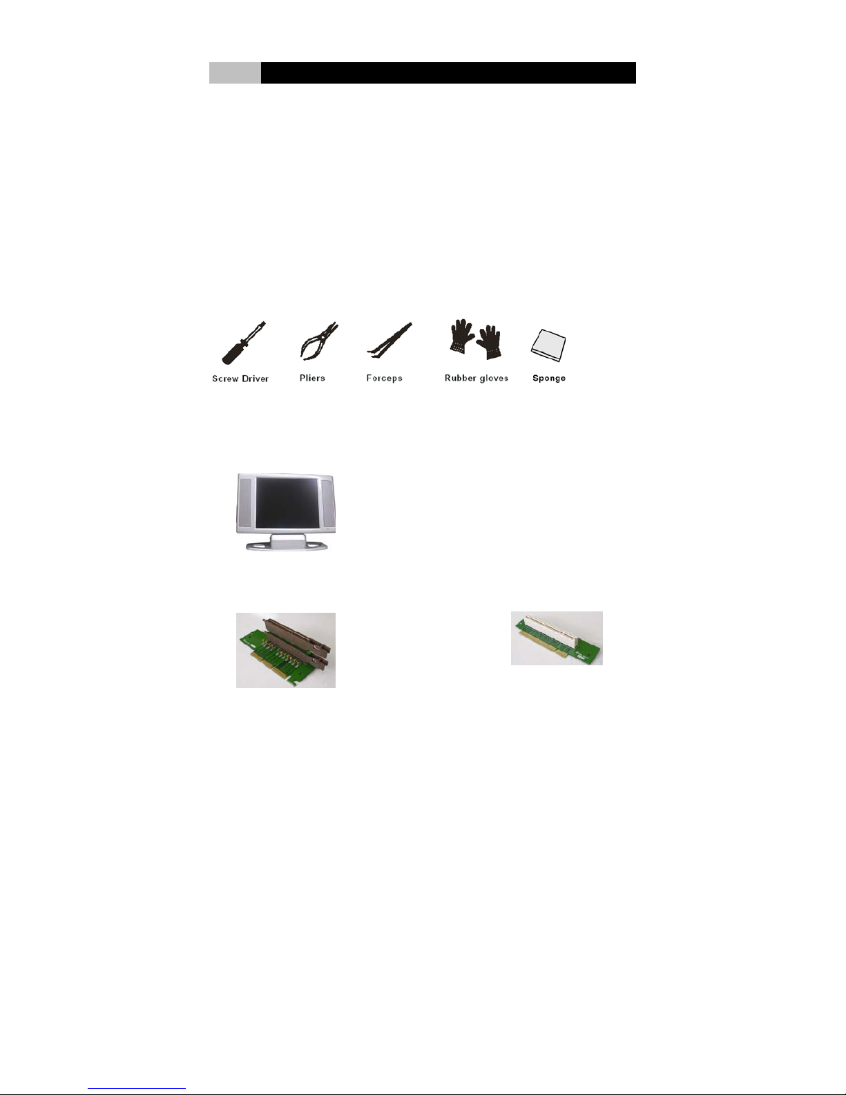
3-1-1 Installation Tools
Screw driver (philips cross head type)
Long nose pliers
Forceps
Anti-static wrist strap or glove
At least 54x40 cm THICK sponge or similar protection materials
3-1-2 Package Checklist for Installation
PCI-Express Riser Card
A
GP Riser Card
PCI Riser Card
LCD PC Barebone
Screws
Page 17
- 12 -
III Hardware Installation
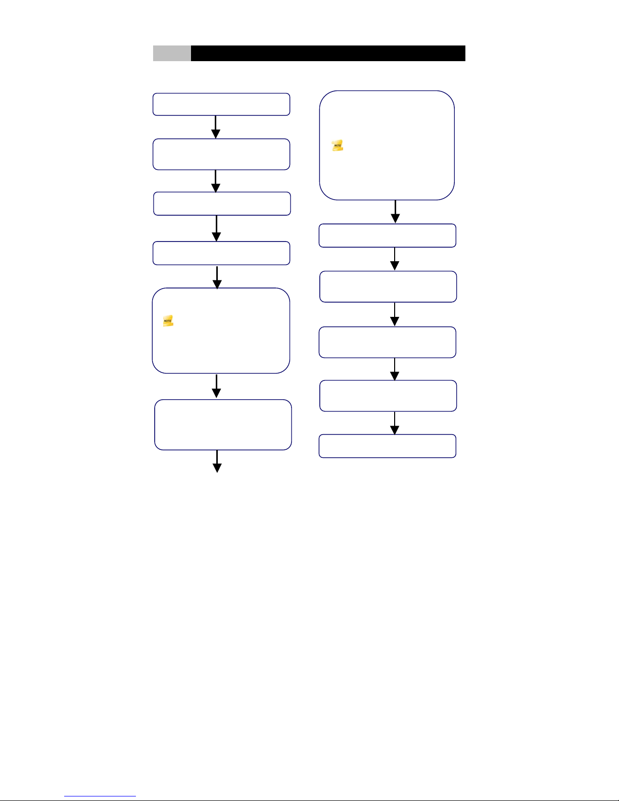
3-2 Installation Flowchart
(1) Start
(2) Remove Back Chassis
Cover
(4) Mount Mainboard
(5) Install CPU, CPU Fan
,
Memory Module
Note:
Please refer to the installation
procedure in the user’s manual
provided by the mainboard
vendor
(3) Mount Hard Disk Drive
(7) Connect Other Cables
(Optical Drive, Audio, HDD,
USB, Reset, HDD LED,
Power LED, Power On.)
Note:
Please refer to the installation
p
rocedure in the user’s manual
p
rovided by the mainboard
vendor.
(8) Install Riser Cards (option
)
(10) Check If All Parts Are
Properly Connected
(11) Replace Back Chassis
Cover
(12) Finish
(6) Connect Mainboard
Audio Cables to activate
Line-out / Mic-in jack on the
f the srear o
y
stem
(9) Connect VGA & Touch
Panel (Optional) Cables
Page 18
- 13 -
III Hardware Installation
3-3 Installation Procedures
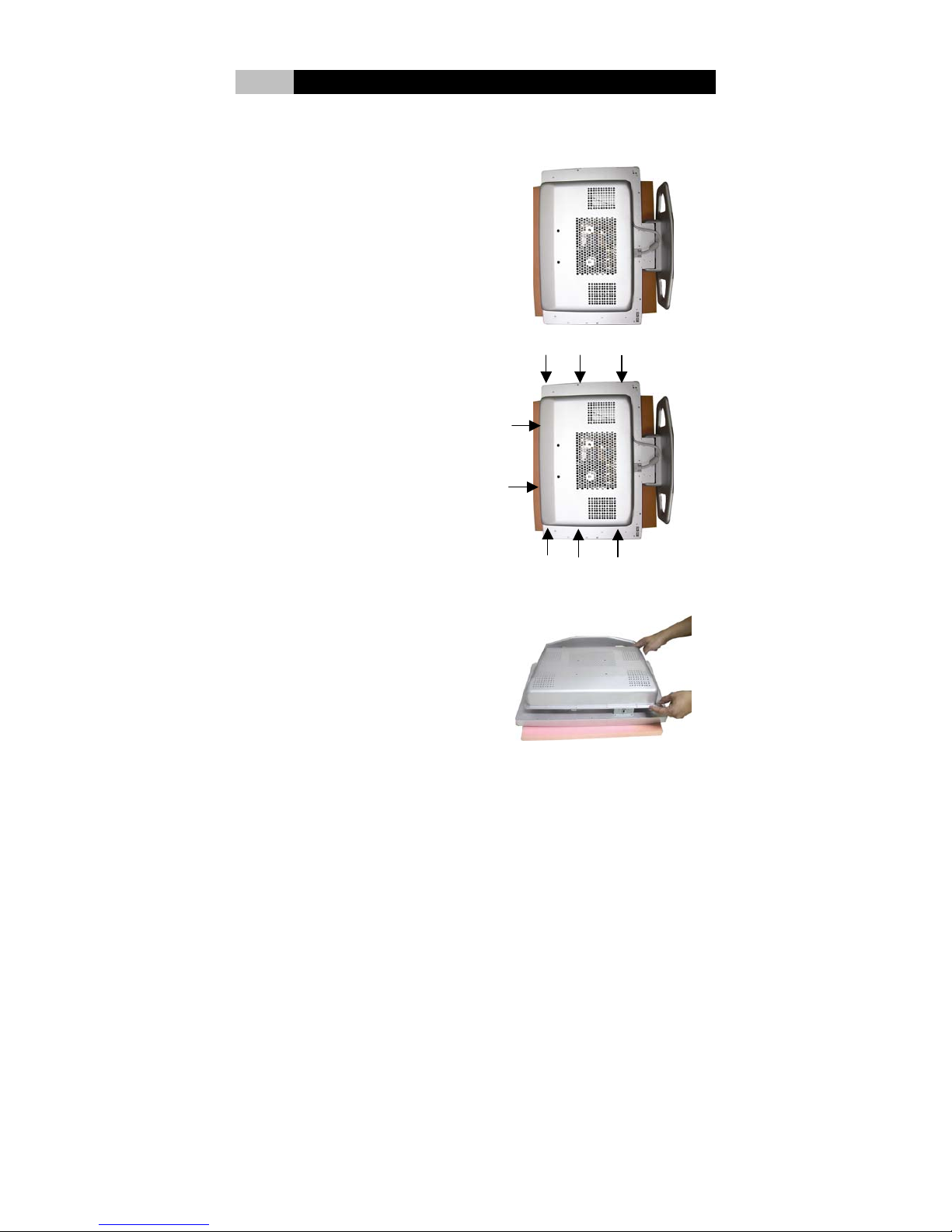
3-3-1 Remove Back Chassis Cover
1. Place the sponge on the platform
to protect the LCD panel. Then
place the system barebone face
down the sponge.
2. Remove the screws (8 pcs) to
open the back cover.
3. Remove the back cover.
Page 19
- 14 -
III Hardware Installation
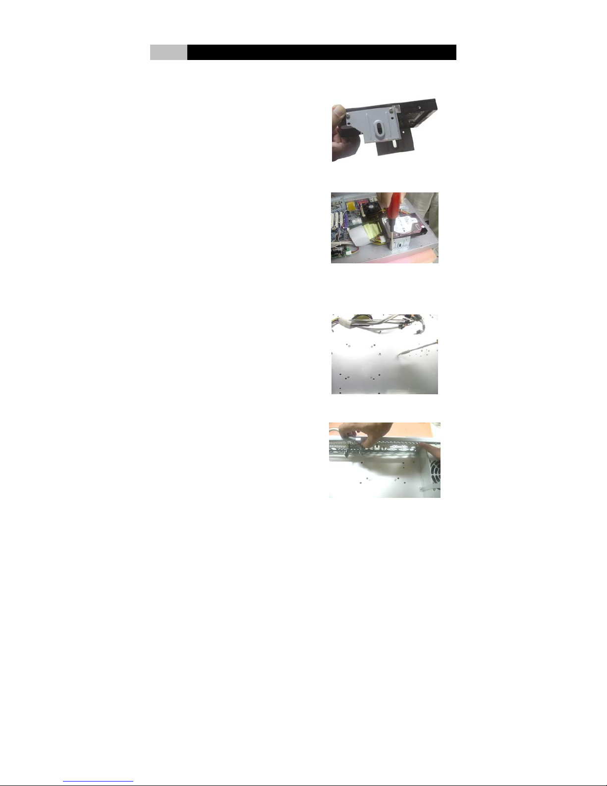
3-3-2 Mount the Hard Disk Drive
Screw type: Mounting screws provided by the Hard Disk Drive vendor.
1. Discharge the HDD mounting
plate from the system plate.
Firmly screw the Hard Drive
onto the HDD mounting plate.
2. Firmly screw the set of HDD and
mounting plate back to the system
plate.
3-3-3 Mount the Mainboard
Screw type: Round-headed mounting screws for mainboard, Standoffs.
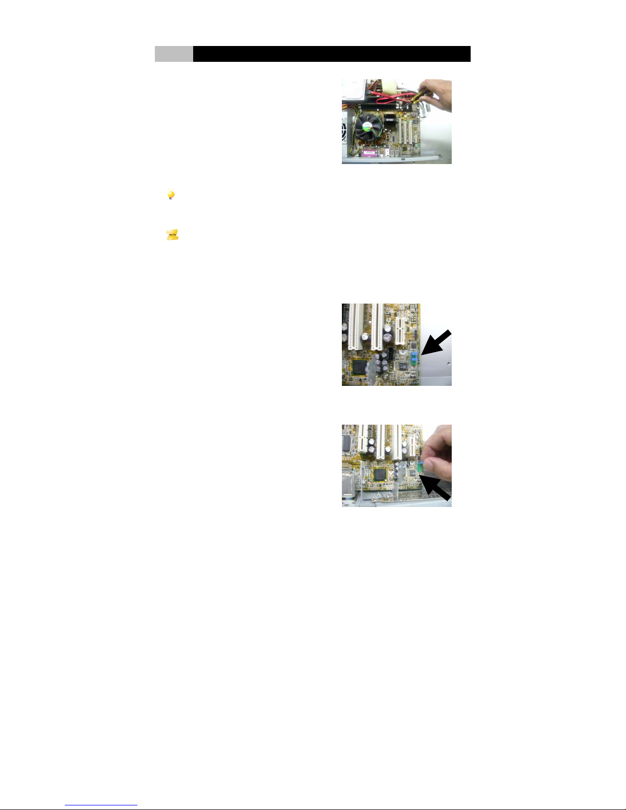
1. Insert the standoffs into the
appropriate screw holes on the
system plate.
2. Insert the I/O shield plate.
Page 20
- 15 -
III Hardware Installation
3. Place the mainboard on the
system plate, aligning the
mainboard mounting holes over
the standoffs. Make sure the
mainboard’s I/O connectors are
aligned with the correct slots on
the I/O shield plate of the system
plate. Insert the mounting screws
through the mainboard mounting
holes into the standoffs and firmly
screw secure.
Caution:
Check to ensure that the underside of the mainboard is not touching the system plate in
any place. If there is any contact the mainboard may short, causing permanent damage.
Note:
Please refer to the user’s manual provided by your mainboard vendor for the installation
procedure of CPU, CPU Fan / Heat sink and Memory Module.
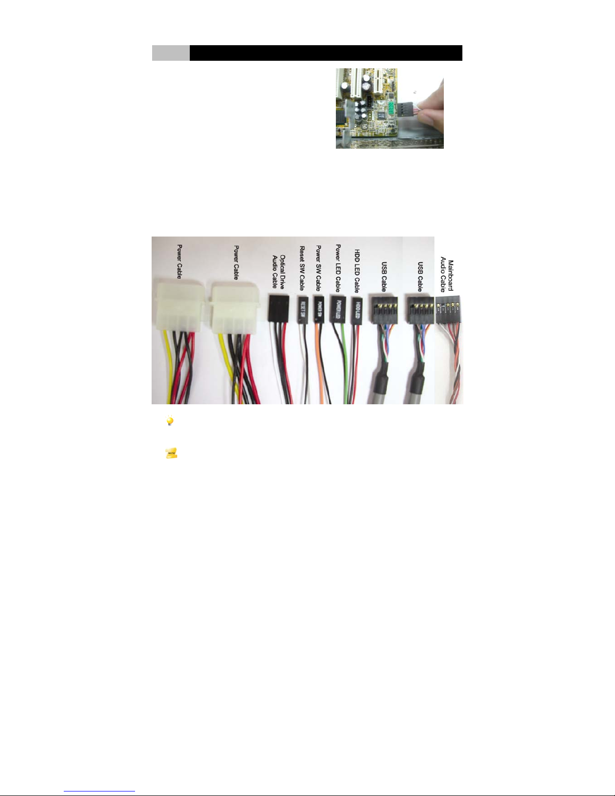
3-3-4 Connect Mainboard Audio Cables to activate Line-out / Mic-in jack on
the rear of the system
1. Find the audio connector which
control the mainboard’s audio
function. The connector has
default jumpers on it.
2. Remove the jumper.
Page 21
- 16 -
III Hardware Installation
3. Connect mainboard’s audio cable
built on the system plate to the
audio connector on the mainboard.
Then the Line-out / Mic-in jack on
the rear of the system can be
activated.
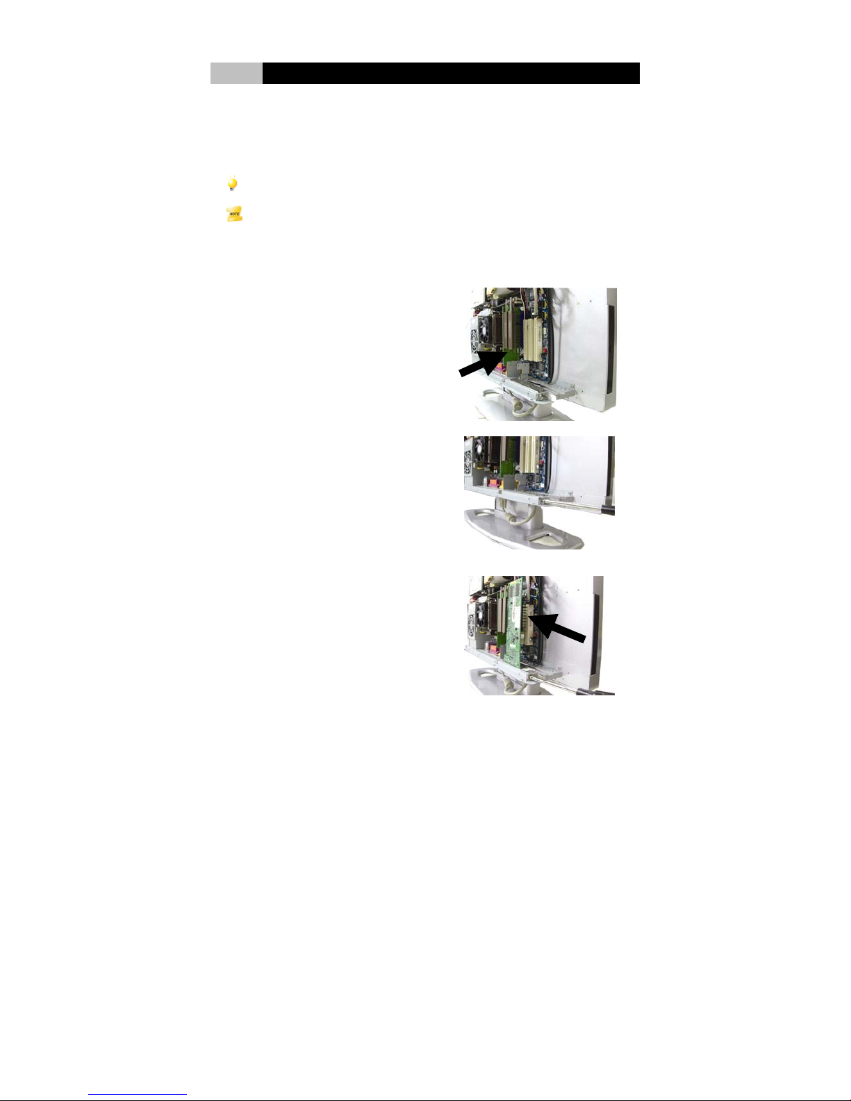
3-3-5 Connect All other Cables
Connect the other cables on the system plate to the mainboard including Optical
Drive Audio, HDD, USB, Reset, HDD LED, Power LED, and Power On. The
following picture contains all the cables that built on the system plate, including the
mainboard’s audio cable mentioned on 3-3-4
Caution:
Make sure the power cable is not connected to AC outlets until after installation is completed.
Note:
To connect the system cables correspond to those on the mainboard, please refer to the
installation procedure in the user’s manual provided by the mainboard vendor.
Page 22
- 17 -
III Hardware Installation
3-3-5 Install the Riser Cards (Option)
Screw type: Round-headed mounting screws for riser card.
The riser cards (AGP riser card / PCI Express riser card / PCI riser card) allow you
to plug the VGA graphic card, PCI Express graphic card and PCI cards into the
mainbaord of the system.
Caution:
Before adding or removing extension cards, make sure to turn off the power first.
Note:
Please refer to the user’s manual provided by the extension card vendor to make any
necessary hardware or software settings.
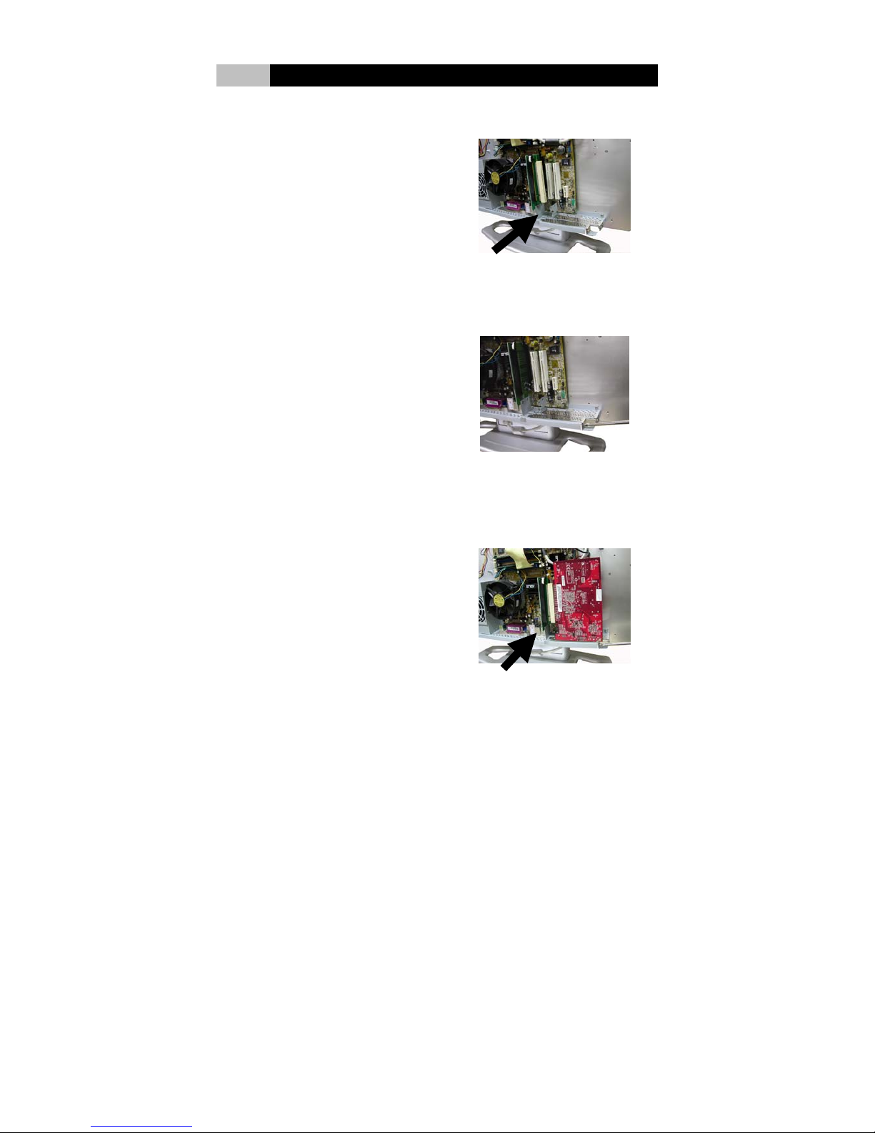
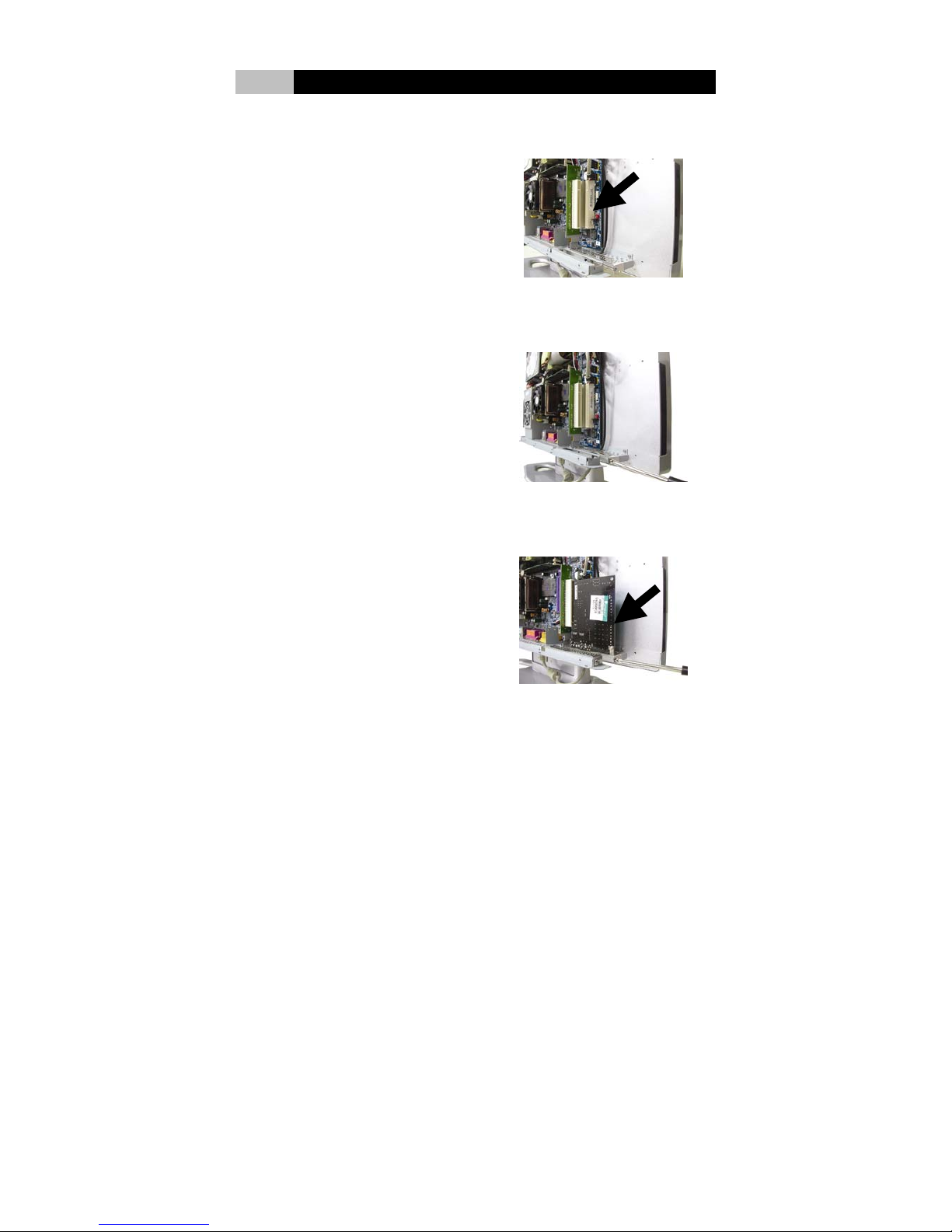
VGA Graphic Card Installation
1. Insert AGP riser card to the AGP
slot on the mainboard.
.
2. Remove the slot cover from the
system case in the space where
the AGP slot to be used.
3. Press the VGA card firmly into the
slot of AGP riser card. Then insert
any screws provided to secure the
VGA card with the system plate.
Page 23
- 18 -
III Hardware Installation
PCI Express Graphic Card Installation
2. Insert PCI Express riser card to
the PCI Express graphic slot on
the mainboard.
.
2. Remove the slot cover from the
system case in the space where
the PCI Express slot to be used.
3. Press the PCI Express graphic
card firmly into the slot of PCI
Express riser card. Then insert
any screws provided to secure the
PCI Express graphic card with the
system plate.
Page 24
- 19 -
III Hardware Installation
PCI Card Installation
1. Insert PCI riser card to the second
PCI slot on the mainboard.
2. Remove the slot cover from the
system case in the space where
the PCI slot to be used.
3. Press the PCI card firmly into the
slot of PCI riser card. Then insert
any screws provided to secure the
PCI card with the system plate.
Page 25
- 20 -
III Hardware Installation
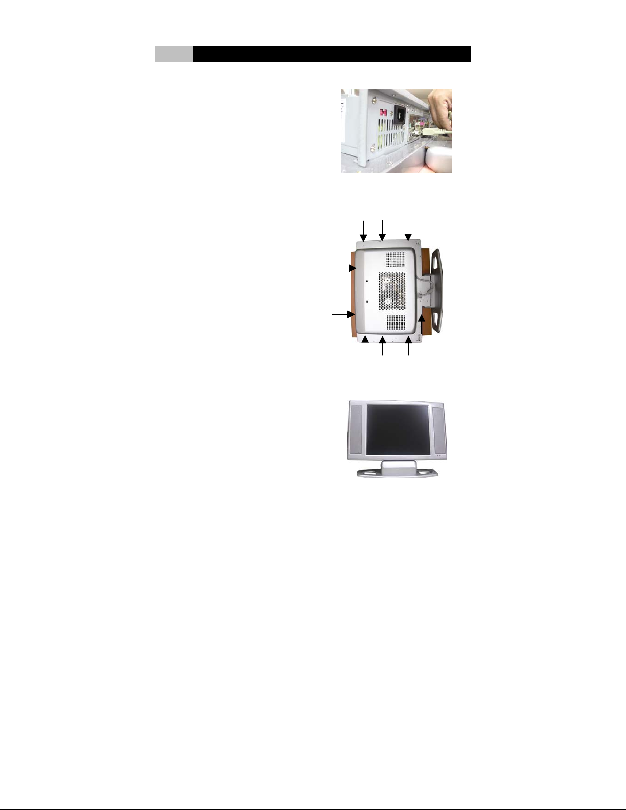
3-3-6 Connect VGA Cable
1. Plug the VGA cable into to the
video port of the mainboard to
activate the monitor.
3-3-7 Finish the Installation
1. Replace the back cover. Insert the
screws (8 pcs) firmly to close the
back cover.
3. Finish the installation. Plug in the
power cord. The system is ready
to go.
Page 26
21
IV LCD Panel Monitor
4-1 LCD Panel Monitor Specifications
This LCD Panel Monitor is a 17” / 19” high-performance intelligent multi-scan
TFT-LCD color monitor. By applying 8 bit digital data, 1280(H) × 1024(V),
16.2M-color (6Bit+FRC) images are displayed on the 17.0” diagonal screen. Input
power voltage is 5.0V for LCD driving. It is designed to be compatible with all
modes between 30 KHz and 80 KHz. (Engineering design 29-70 KHz). The
microprocessor-based design was implemented with the user in mind, providing
digital user controls for precision, auto-synchronization and auto-sizing for
convenience and user-programmability for flexibility. The LCD panel specifications
are following.
17” LCD panel specifications:
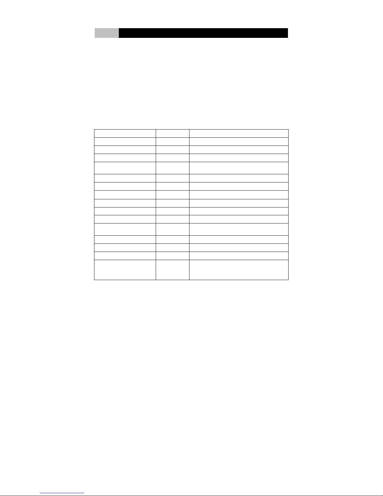
ITEM Unit SPECIFICATION
Active Area
〔mm〕
337.920(H) x 270.336(V)
Number of Pixels 1280(H) x 1024(V)
Pixel Pitch
〔mm〕
0.264(H) x 0.264(V)
Color Pixel
Arrangement
RGB vertical stripe
Display Mode Normally white
Number of Colors 16.2M (6 Bit + FRC)
Brightness
〔cd /㎡〕 250 cd /㎡ @ 7 mA (Typ.)
Viewing Angle 140°(H) / 130°(V)
Contrast Ratio (Max) 450 : 1 (Typ)
Response Time (Total)
〔msec〕
16ms (Typ, on/off)
Power Consumption
(VDD line + CCFL line)
〔Watt〕
25W (w/o Inverter, All black pattern)
Physical Size
〔mm〕
358.5(W)X296.5(H)X17.0(D)
Module Weight
〔g〕
1800
Surface Treatment Anti-glare, hard coating (3H)
Temperature Range
Operating
Storage (Shipping)
〔℃〕
〔℃〕
0 to +50
-20 to +60
Page 27
22
IV LCD Panel Monitor
19” LCD panel specifications:
ITEM Unit SPECIFICATION
Active Area
〔mm〕
376.32(H) x 301.056(V)
Number of Pixels 1280(H) x 1024(V)
Pixel Pitch
〔mm〕
0.294(H) x 0.294(V)
Color Pixel
Arrangement
RGB vertical stripe
Display Mode Normally white
Number of Colors 16.7M (RGB 8-bit data)
Brightness
〔cd /㎡〕 300 cd /㎡ @ 7 mA (Typ.)
Viewing Angle 170°(H) / 130°(V)
Contrast Ratio (Max) 700 : 1 (Typ)
Response Time (Total)
〔msec〕
16ms (Typ, on/off)
Power Consumption
(VDD line + CCFL line)
〔Watt〕
27.5W (w/o Inverter, All black pattern)
Physical Size
〔mm〕
396(W)X324(H)X17.5(D) (Typ)
Module Weight
〔g〕
2500
Surface Treatment Anti-glare, hard coating (3H)
Temperature Range
Operating
Storage (Shipping)
〔℃〕
〔℃〕
0 to +50
-20 to +60
4-2 Activate the Monitor
Before starting the system, make sure to plug the VGA cable into to the video port
of the mainboard to activate the monitor.
4-3 Adjust the Monitor
4-3-1 Monitor Control Keys
There are 5 control keys on the right side of chassis for user to adjust the monitor
including
Power, Up, Down, Menu and Auto. The
descriptions of these keys are followings.
1.
Power Key: Turn the System and LCD Panel power on or off.
2.
Up key: Make cursor moves up to switch the previous function in sequence.
3.
Down key: Make cursor moves down to switch the previous function in sequence.
Page 28
23
IV LCD Panel Monitor
4.
Menu key: Enter main-menu and sub-menu.
5.
Auto key: Adjust vertical position, phase, horizontal position and pixel
clock automatically.
4-3-2 Display Adjustment
MAIN MENU
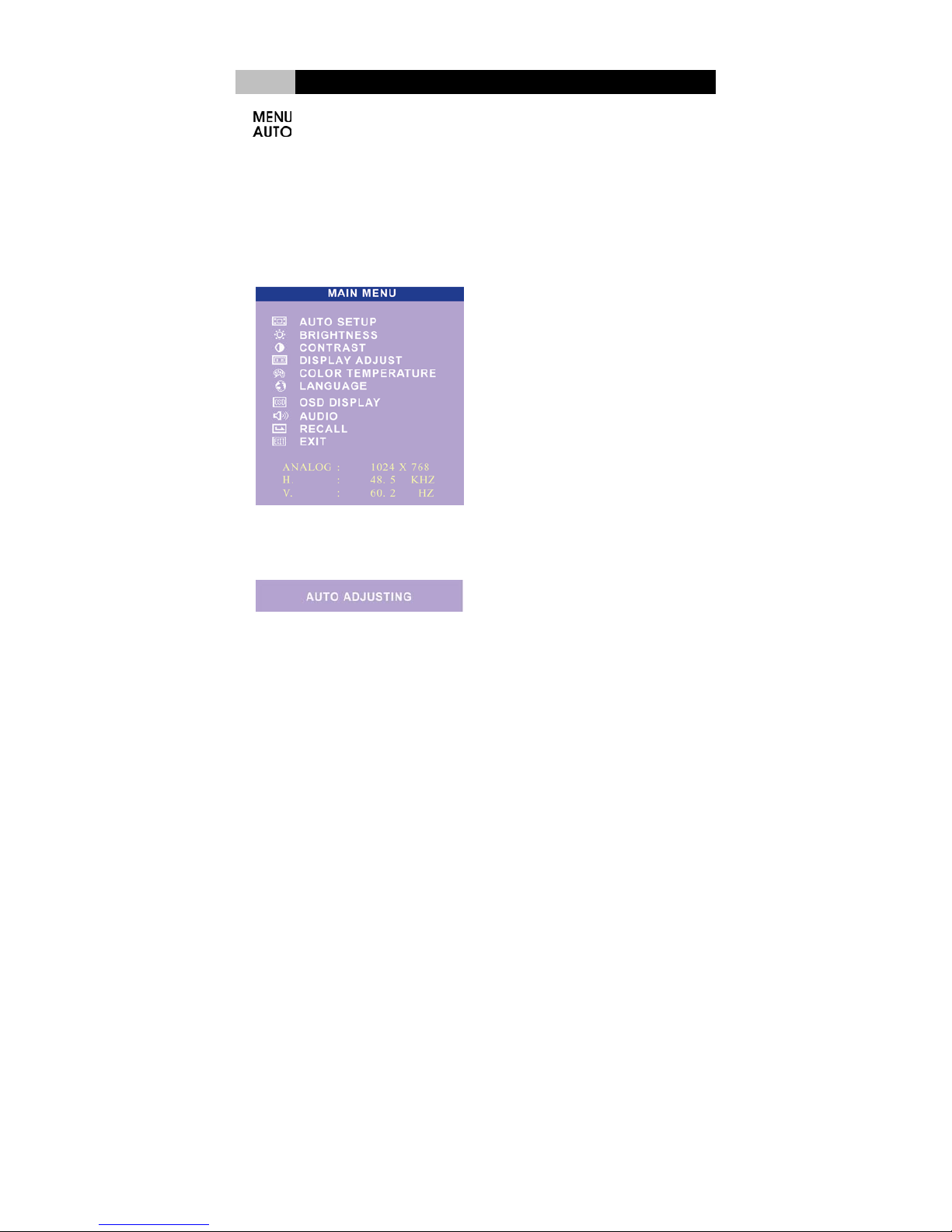
Press ” Menu” key to enter “MAIN MENU”. The Control functions include Auto Setup,
Brightness, Contrast, Display Adjust, Color Temperature, Language, OSD Display,
Audio, Recall and Exit. At the end of this menu shows the current resolution as well as
horizontal and vertical frequency status.
A. AUTO SETUP: In the main menu, choose “AUTO ADJUST”. Press “ Menu” key,
the system will adjust vertical position, phase, horizontal position and pixel
clock automatically. Exit automatically in 5 seconds.
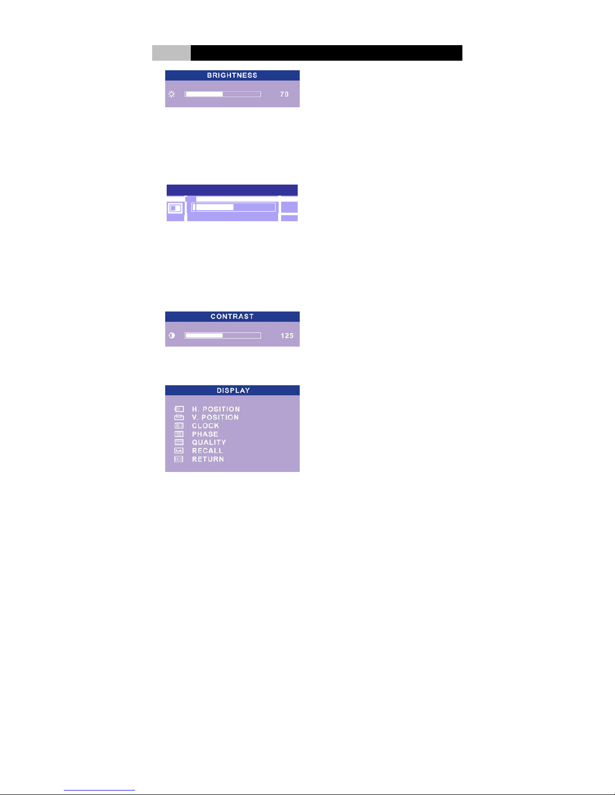
B. BRIGHTNESS: This function could adjust the brightness of the picture. There
are two ways to adjust the brightness of display. Adjust the brightness or
backlight level of the panel.
In the main menu, choose “BRIGHTNESS”. Press “Menu” key to enter the
sub-menu. Choose “BRIGHTNESS” and press “ Menu” key again to show the
level. Press “Up”/”Down” key to adjust the brightness level. The scale can be
adjusted from maximum (255) to minimum (0). Press “Menu” Key to return to
the sub-menu. Choose “RETURN” to save the adjustment and back to the main
menu. Choose “EXIT” to exit. Or wait about 5 seconds for auto exit.
Page 29
24
IV LCD Panel Monitor
Or in the main menu, choose “BRIGHTNESS”. Press “Menu” key to enter the
sub-menu. Choose “Backlight” and press “ Menu” key again to show the level.
Press “Up”/”Down” key to adjust the backlight level. The scale can be adjusted
from maximum (127) to minimum (0). Press “Menu” Key to return to the
sub-menu. Choose “RETURN” to save the adjustment and back to the main
menu. Choose “EXIT” to exit. Or wait about 5 seconds for auto exit.
BACKLIGHT
80
C. CONTRAST: adjust the difference between the light and dark areas.
In the main menu, choose “CONTRAST”. Press “ Menu” key, then use
“Up”/”Down” key to adjust the contrast level. The scale can be adjusted from
maximum (255) to minimum (0). Press “Menu” Key to return to the sub-menu.
Choose “RETURN” to save the adjustment and back to the main menu. Choose
“EXIT” to exit. Or wait about 5 seconds for auto exit.
D. DISPLAY ADJUST: adjust display’s function of the picture.
Page 30
25
IV LCD Panel Monitor
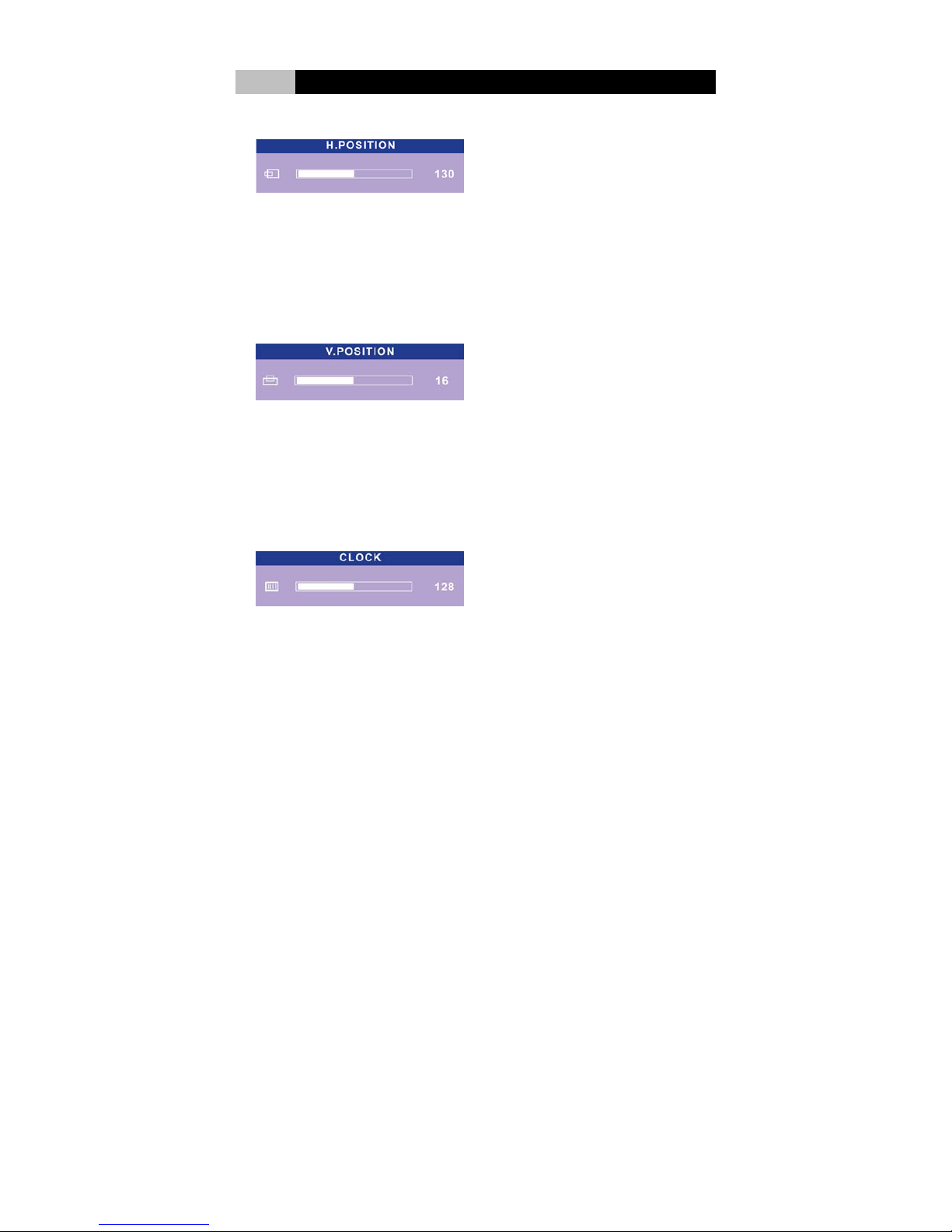
a. H. (Horizontal) POSITION: adjusts the horizontal position of the display.
In the main menu, choose “DISPLAY ADJUST”. Press “ Menu” key to enter the
sub-menu. Choose “H. POSITION” and press “ Menu” key again to show the
position level. Press “Up”/”Down” key to adjust the position level. The scale can
be adjusted from maximum (255) to minimum (0). Press “Menu” Key to save
the adjustment and return to the sub-menu. Choose “RETURN” to go back to
the main menu. Choose “EXIT” to exit. Or wait about 5 seconds for auto exit.
b. V. (Vertical) POSITION: adjusts the vertical position of the display.
In the main menu, choose “DISPLAY ADJUST”. Press “ Menu” key to enter the
sub-menu. Choose “V. POSITION” and press “ Menu” key again to show the
position level. Press “Up”/”Down” key to adjust the position level. The scale can
be adjusted from maximum (31) to minimum (0). Press “Menu” Key to save the
adjustment and return to the sub-menu. Choose “RETURN” to go back to the
main menu. Choose “EXIT” to exit. Or wait about 5 seconds for auto exit.
.
c. CLOCK: adjusts the frequency of the pixel.
In the main menu, choose “DISPLAY ADJUST”. Press “ Menu” key to enter the
sub-menu. Choose “CLOCK” and press “ Menu” key again to show the position
level. Press “Up”/”Down” key to adjust the position level. The scale can be
adjusted from maximum (255) to minimum (0). Press “Menu” Key to save the
adjustment and return to the sub-menu. Choose “RETURN” to go back to the
main menu. Choose “EXIT” to exit. Or wait about 5 seconds for auto exit.
Page 31
26
IV LCD Panel Monitor
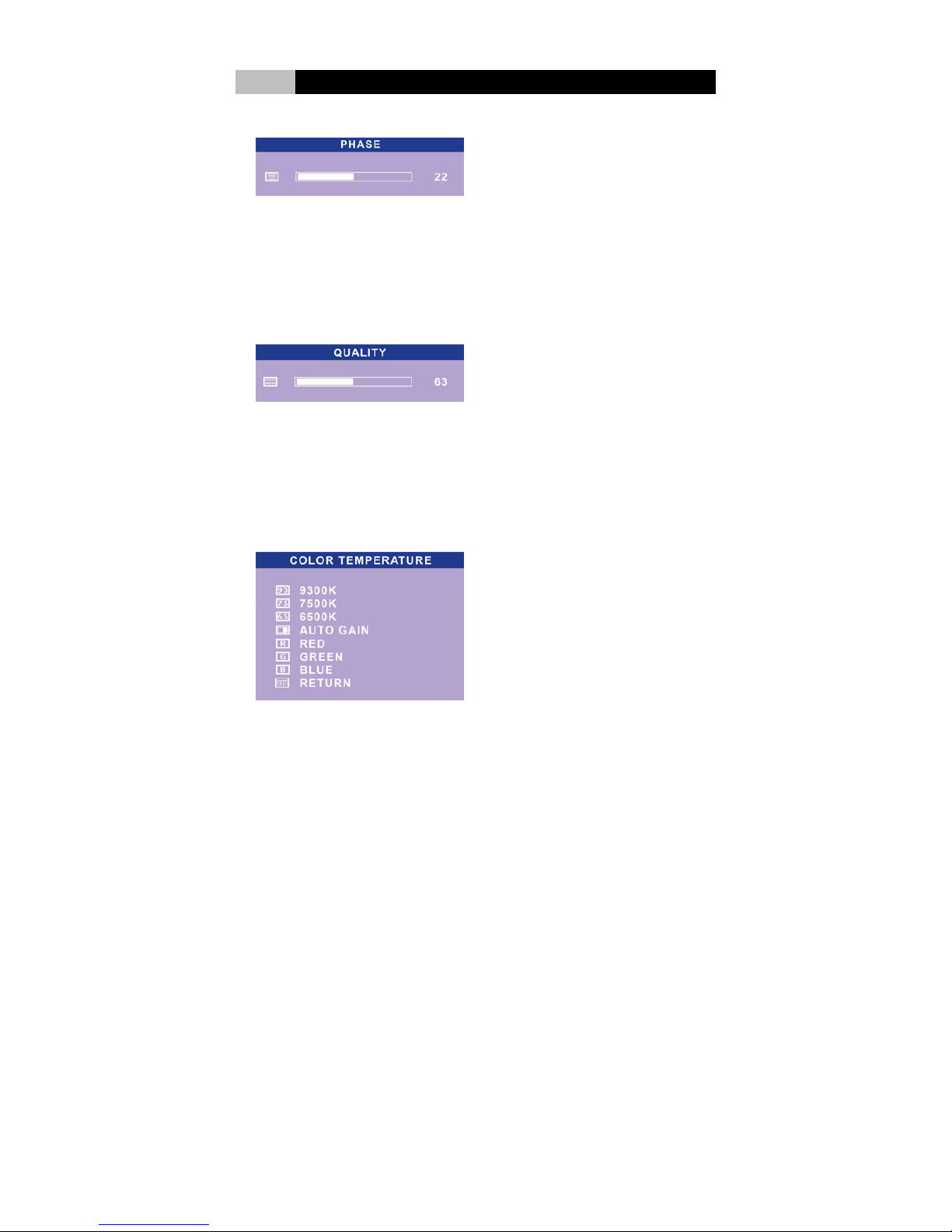
d. PHASE: adjusts the phase of pixel clock.
In the main menu, choose “DISPLAY ADJUST”. Press “ Menu” key to enter the
sub-menu. Choose “PHASE” and press “ Menu” key again to show the position
level. Press “Up”/”Down” key to adjust the position level. The scale can be
adjusted from maximum (31) to minimum (0). Press “Menu” Key to save the
adjustment and return to the sub-menu. Choose “RETURN” to go back to the
main menu. Choose “EXIT” to exit. Or wait about 5 seconds for auto exit.
e. QUALITY: adjusts the scanning filter and sharpness of the picture.
In the main menu, choose “DISPLAY ADJUST”. Press “ Menu” key to enter the
sub-menu. Choose “QUALITY” and press “ Menu” key again to show the
position level. Press “Up”/”Down” key to adjust the position level. The scale can
be adjusted from maximum (190) to minimum (0). Press “Menu” Key to save
the adjustment and return to the sub-menu. Choose “RETURN” to go back to
the main menu. Choose “EXIT” to exit. Or wait about 5 seconds for auto exit.
E. COLOR TEMPERATURE: adjust color temperature and color scale.
In the main menu, choose “COLOR TEMPERATURE”. Press “Menu” key to
enter the sub-menu and there are three color temperature and three colors can
be chosen. Press “Up”/”Down” key to choose color temperature (9300K(Cool),
7500K(Nature) or 6500K(Warm); press “Menu” key to save the choice.
Choose ”Return” to go back to the main menu. Or press “Up”/”Down” key to
Page 32
27
IV LCD Panel Monitor
choose color (Red, Green, Blue). Press “ Menu” key again in the sub-menu to
show color level. Press “Up”/”Down” key to adjust the color level. The scale can
be adjusted from maximum (255) to minimum (0). Press “Menu” key to save the
choice. Choose ”Return” to go back to the main menu. Or choose ”AUTO GAIN”
to make the auto white balance adjusting. Press “Menu” key to save the
adjustment. Choose ”Return” to go back to the main menu. Choose “SAVE AND
EXIT” to exit. Or wait about 5 seconds for auto exit.
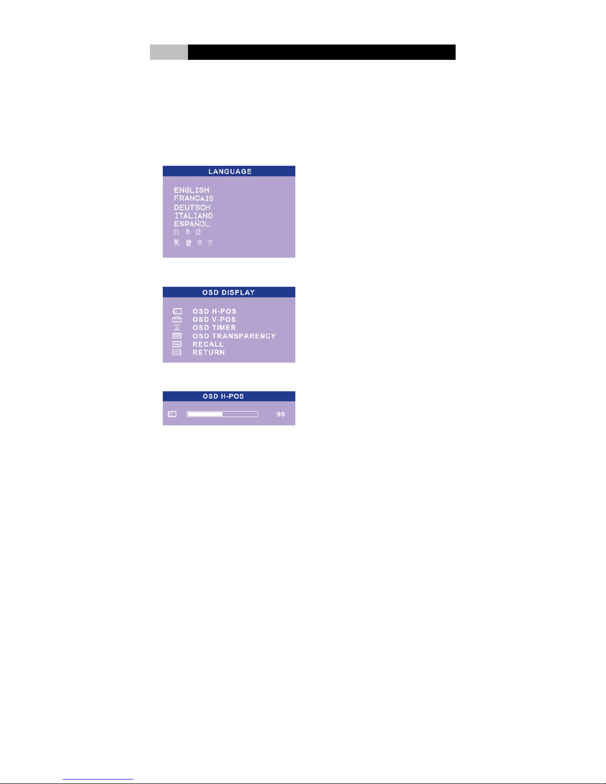
F. Language: to select the language for OSD display
G. OSD DISPLAY: adjusts the function of On Screen Display (OSD).
a. OSD H-POS: adjusts OSD horizontal position of OSD display.
In the main menu, choose “OSD DISPLAY”. Press “Menu” key to enter the
sub-menu. Choose “OSD H-POS” and press “Menu” key again to show the
position level. Press “Up”/”Down” key to adjust the position level. The scale can
be adjusted from maximum (244) to minimum (0). Press “Menu” Key to save
the adjustment and return to the sub-menu. Choose “RETURN” to go back to
the main menu. Choose “EXIT” to exit. Or wait about 5 seconds for auto exit.
Page 33
28
IV LCD Panel Monitor
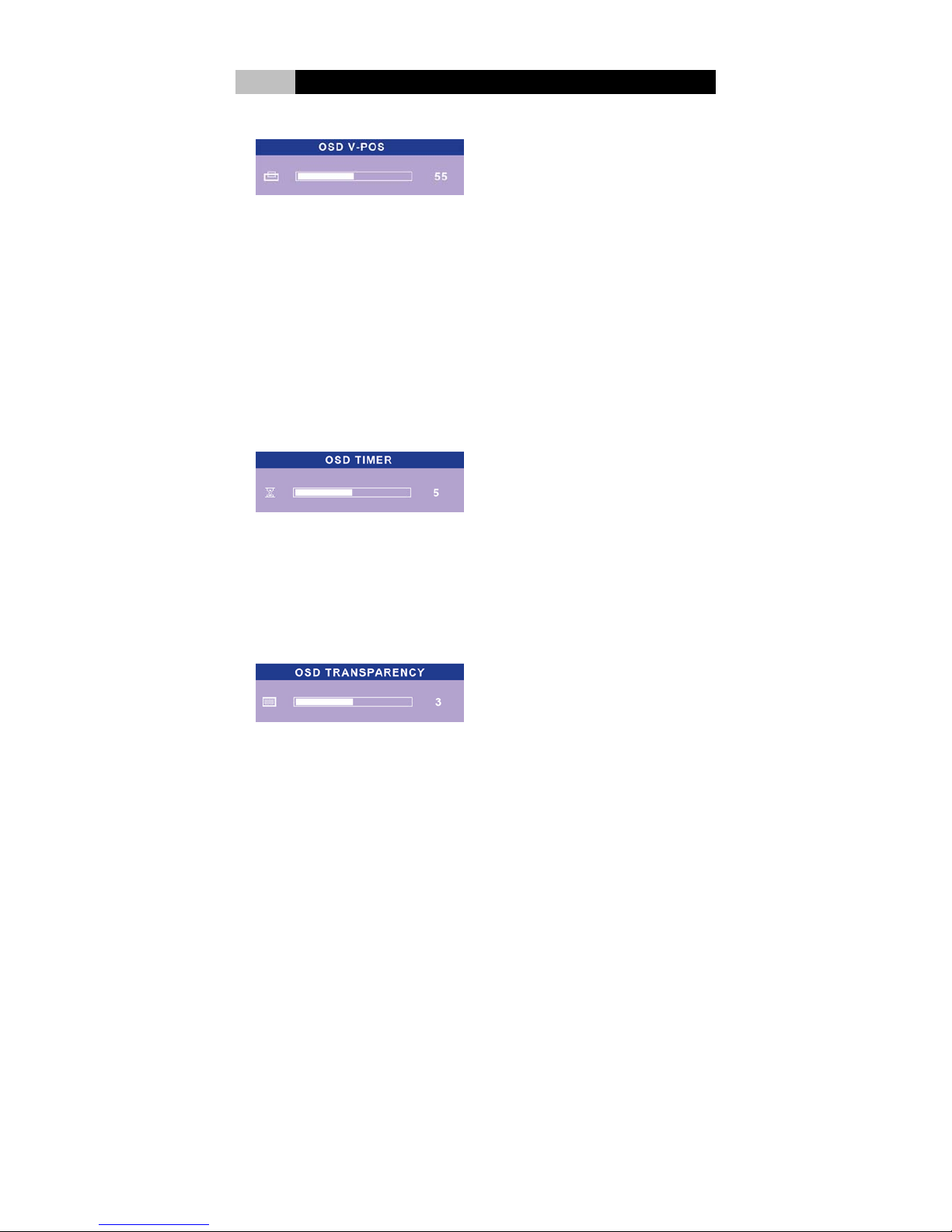
b. OSD V-POS: adjusts OSD vertical position.
In the main menu, choose “OSD DISPLAY”. Press “Menu” key to enter the
sub-menu. Choose “OSD V-POS” and press “ Menu” key again to show the
position level. Press “Up”/”Down” key to adjust the position level. The scale can
be adjusted from maximum (174) to minimum (0). Press “Menu” Key to save
the adjustment and return to the sub-menu. Choose “RETURN” to go back to
the main menu. Choose “EXIT” to exit. Or wait about 5 seconds for auto exit.
c. OSD TIMER: adjusts the duration of OSD.
In the main menu, choose “OSD DISPLAY”. Press “Menu” key to enter the
sub-menu. Choose “OSD TIMER” and press “Menu” key again to show the
position level. Press “Up”/”Down” key to adjust the position level. The scale can
be adjusted from maximum (100) to minimum (0). Press “Menu” Key to save
the adjustment and return to the sub-menu. Choose “RETURN” to go back to
the main menu. Choose “EXIT” to exit. Or wait about 5 seconds for auto exit.
d. OSD TRANSPARENCY: adjusts the transparency of OSD.
In the main menu, choose “OSD DISPLAY”. Press “Menu” key to enter the
sub-menu. Choose “OSD TRANSPARENCY” and press “Menu” key again to
show the position level. Press “Up”/”Down” key to adjust the position level. The
scale can be adjusted from maximum (7) to minimum (0). Press “Menu” Key to
save the adjustment and return to the sub-menu. Choose “RETURN” to go back
to the main menu. Choose “EXIT” to exit. Or wait about 5 seconds for auto exit.
Page 34
29
IV LCD Panel Monitor
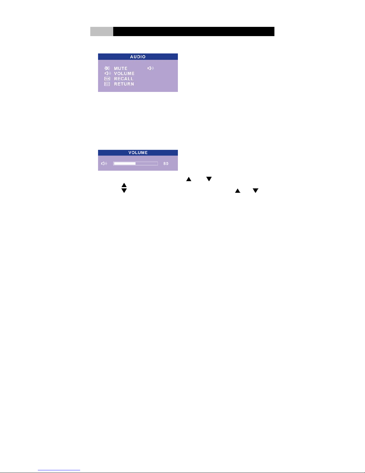
H. AUDIO: adjust speaker volume.
In the main menu, choose “AUDIO”. Press “ Menu” key to enter the sub-menu
Press “Up”/”Down” key to choose “Mute” or “Volume”. When choose “Mute”;
press “ Menu” key to switch ON or OFF. When choose “VOLUME”, press
“Menu” key to show the volume level. Press “Up”/”Down” key to adjust the
volume level. The scale can be adjusted from maximum (127) to minimum (0).
Press “Menu” Key to save the adjustment and return to the sub-menu. Choose
“RETURN” to go back to the main menu. Choose “EXIT” to exit. Or wait about 5
seconds for auto exit.
Also, to control audio, there’s hot keys “
Up”, “ Down” can be used.
a. Press
key to switch the mode between “Mute” and Volume”.
b. Press
key to show the volume of audio output. Press “ Up, Down
to adjust the volume. Press “Menu” to save and exit.
I. RECALL: back to the present setting automatically
In the main menu, choose “RECALL”. Press “Menu” key, the system will
automatically recall the present setting. Choose “EXIT” to exit. Or wait about 5
seconds for auto exit.
J EXIT: left the main menu.
When finish adjustments, in the main menu, choose “EXIT”; press “ Menu” key to
exit the whole setting.
Page 35

30
V Troubleshooting
When you encounter a problem, first try to go through the recommendations
followings. If the error continues, contact your local dealer for service information.
1. Check to see if the problem persists when all the external devices are removed.
2. Check if any incorrect or loose cable connections. Make sure the latches on the
connectors latch securely on to the receptor end.
3. Be sure all the device drivers are installed properly.
4. Be sure you have not performed an incorrect setting on the hardware devices in
the BIOS Setup utility. A faulty setting may cause the system to misbehave.
5. Not all peripheral are plug-and-play capable. You need to restart the system
with these devices powered up and connected first.
6. Be sure to go to BIOS setup and load DEFAULT setting after any BIOS updated.
7. If external devices such as Keyboard, mouse, USB camera, scanner, SCSI
card… do not work correctly when connected to the system, usually it’s the
device’s own problem. Consult the device’s manufacturer first.
Q&A
Q:
LCD PC system won’t start.
A: Check if power cord is connected properly.
Q: The system starts, but there is no display.
A: 1. Check if the VGA plug connected properly to the Video port.
2. Check the LCD Panel settings and brightness.
3. Shutdown the PC, disconnect the power and check if the graphics card is
correctly installed.
Q: Hard drive or Optical drive error
A: 1. Check drive configuration in BIOS.
2. Check drive jumper settings (master/slave).
3. Check drive cables are properly connected.
4. Check the correct drivers have been installed.
Q: Memory Error
A: 1. Check the user’s manual of mainboard & memory to see if installed the
correct type of memory.
2. Shutdown the system, disconnect the power and check if the memory is
correctly installed.
Q: No Speaker output
A: 1. Check if the audio cable connected properly to the Lin-out port.
2. Check if the monitor volume value is set properly.
Note:
Please be aware that this is not a comprehensive support guide. For more detailed
information please refer to the user’s manual provided by your component vendors or contact
technical support.
 Loading...