

VANCO VPW-280709 User Manual

HDMI® MATRIX
SELECTOR SWITCH
PRODUCT MANUAL
Vanco Part Numbers:
VPW-280709 (8X8)
www.vanco1.com • info@vanco1.com • 800-626-6445
www.vanco1.com • 888.769.4156
Technical Support

DEAR CUSTOMER
Thank you for purchasing this product.
For optimum performance and safety, please
read these instructions carefully before
connecting, operating or adjusting this product.
Please keep this manual for future reference.
This product is 100% inspected and tested in the United States
to verify HDMI performance parameters.
WARNING
1. Do not expose this unit to water, moisture,
or excessive humidity.
2. Do not install or place this unit in a built-in
cabinet, or other conned space without
adequate ventilation.
3. To prevent risk of electrical shock or re
hazard, due to overheating, do not obstruct
unit’s ventilation openings.
4. Do not install near any source of heat,
including other units that may produce heat.
5. Do not place unit near ames.
6. Only clean unit with a dry cloth.
7. Unplug unit during lightening storms, or
when not used for an extended period
of time. A surge protector is strongly
recommended.
8. Protect the power cord from being walked
on or pinched, particularly at the plugs.
9. Use unit only with accessories specied by
the manufacturer.
10. Refer all servicing to qualied personnel.
CAUTION
HDMI is a very complex technology requiring continuous authentication of the signal and the same
video resolution and audio settings on all electronic equipment in the system. When there are multiple
sources and displays, the video resolution and audio setting on all connected units must be adjusted
to correspond with that of the display having the lowest video and audio capability.
2
www.vanco1.com

FEATURES
VPW-280709 is an 8x8 HDMI matrix switch. It allows any of eight sources (Blue-Ray player, cable or satellite
receiver, game system, etc.) to be routed to any of eight displays simultaneously, whether the source is HDCP
Compliant or not. Users can choose several different ways to control the matrix; using (IR) infrared extension
receivers, RS-232,or RS-485 control protocols, and Ethernet or the supplied remote control. IR emitters in
the matrix are for controlling the sources. The IR control signal can be from remote locations via STP/UTP type
connections on the rear panel.
The 8x8 HDMI matrix switch has the ability to control equalization and amplication to ensure that the HDMI
signal’s transmission through long cables occurs without loss of quality. The transmission distance of STP/UTP
outputs is up to 164 feet (50 meters) at 1080p, together with the infrared control signal.
This 8x8 HDMI matrix switch offers solutions for digital entertainment centers, HDTV retail and show site
installations, HDTV, STB, DVD and projector applications. This addresses noise, space and security concerns,
data center control, information and signage distribution, conference room presentations, and school and
corporate training environments.
Vanco Powered by WyreStorm HDMI® 8 x 8 Matrix Selector Switch over 2 x UTP
Part # VPW-280709
• Offers Unprecedented Flexibility and
Convenience by Extending High Denition Audio/
Video Signals from any of 8 HDMI Sources to
any of 8 Remote Displays over Single Cat5e/
Cat6 Cables
• Transmission Range: Extends 1080p
resolutions up to 100 ft over Single or Cat5e
Cables; Extends 1080p resolutions up to 110 ft
over Single Cat6 Cables
• Reading and saving EDID function from displays
• Additional RJ45 Output allows for transmission
of IR signals over Single Cat5e/Cat6 Cable
• Includes Eight IR emitters to control the HDMI
sources
• Includes RS232 Exdender over Cat5e/Cat6
• 19” Rack Mounting
• 8x8 Matrix Dimensions: 17.25” W x 7” H x
15.25” D
• Receiver Dimensions (Not Included): 2.625” W
x .75” H x 4.5” D
• Includes Remote Control
• High Speed Chip Set that Supports 3D and 4K
x 2K
• Six switching modes are available: panel
buttons, local IR, IR call back from remote
locations, RS-232, RS-485 and Ethernet
• Each output includes one HDMI type A
connecter and a set of dual RJ-45 connectors
as the second mirrored HDMI output. The two
outputs can work simultaneously. The UTP
outputs support both dual and single Cat 5e/
Cat 6 UTP/STP cables
• Each port supports both HDMI and DVI inputs
• Full HD1080P/60Hz
• HDCP Compliant
• Supports Digital Audio Format, DTS-HD/Dolby-
True HD/LPCM7.1/AC3/DTS/DSD
• Tested for Compatibility with all leading HD
Video brands
• Tested with 7.1 Home Theater Systems
888.769.4156
3

PACKAGE CONTENTS
Before attempting to use this unit, please check the packaging and make sure the following items are
contained in the shipping carton:
• 8x8 Matrix Selector Switch
• 110-240V AC Power cable
• Remote Control
• 1 IR receiver cable
• 8 IR transmitter cables
PANEL DESCRIPTION
FRONT PANEL
• 1 USB to UART cable
• 1 RS-232 to RS-485 converter
• Instruction manual
• Mounting ears
• Barrier chip
1. Power switch
2. Output selection push button (Use it to choose the output channel you want to change)
3. Action Conrmation button (Push the ‘Enter’ button to conrm the changing of input channel to the output)
4. Input selection knob (Rotate it to select the input to the output)
5. LED indicator of input for output port 1 to 8
6. IR window
4
www.vanco1.com

BACK PANEL
1. IR extension
2. DIP switch setting
3. IR emitter, corresponding to the Input port from
1 to 8
4. RS-485 port
5. LAN port
CONNECT AND OPERATE
6. RS-232 port
7. Power input
8. Input ports 1 to 8
9. Output 1 to 8 with HDMI and Cat5e/Cat 6
10. ISP Port
NOTE: RS-232 port and LAN port are for matrix
control. The LAN port is connected to the computer
via cross-over UTP and connected to the router or
switcher via direct UTP.
1. Connect the HDMI input sources
2. Connect the standard HDMI outputs
3. Connect two Cat5e cables to both the STP/UTP
outputs of the Matrix and inputs of STP/UTP
receivers. The cable termination must follow the
standard of EIA/TIA 568B, if used in Single UTP
mode, just connect CAT5E -2).
4. Connect the HDMI output into the STP /UTP
receiver
5. Connect the IR RX receiving cable into STP/UTP
receiver IR RX and connect the IR TX cable into
matrix 9 IR emitter
888.769.4156
6. Power on the input source you want to show.
Keep the unused input power off, otherwise it
may interfere with the normal display
7. Connect the power supply into the matrix
8. Turn on the power, when the LED panel stops
ashing circularly, the initialization of the matrix
is ready
9. Turn on the displays you want to watch
10. Use the remote supplied or push the button on
the front panel to choose input source, or using
infrared extension receiver, RS-232, RS-485 or
LAN port to do the control.
5
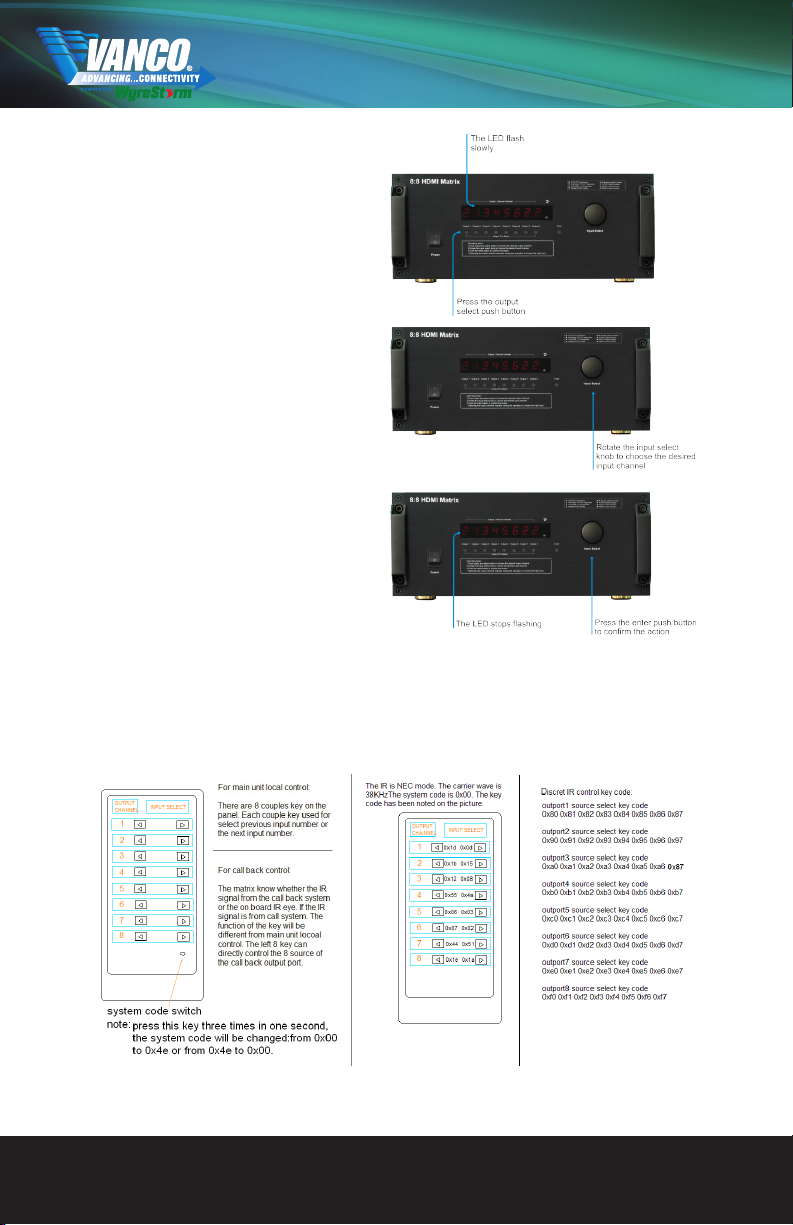
OPERATION ON THE FRONT
PANEL
1. First: Press the output select button to the
output channel which you want to change. Then
the corresponding LED of the output channel will
blink slowly.
2. Second: Rotate the input select knob to choose
the desired input channel.
3. Third: Press the ‘Enter’ button to conrm the
action. Then the LED stops blinki
CONTROL VIA REMOTE CONTROL
NOTE: if the IR remote isn’t working, please press the system code switch key
6
www.vanco1.com
 Loading...