

Vanco HDBaseT Lite Instruction Manual
1
Instruction Manual
Thank you for choosing this product.
Please read these instructions carefully before installing to avoid complications later.
Vanco Powered by WyreStorm
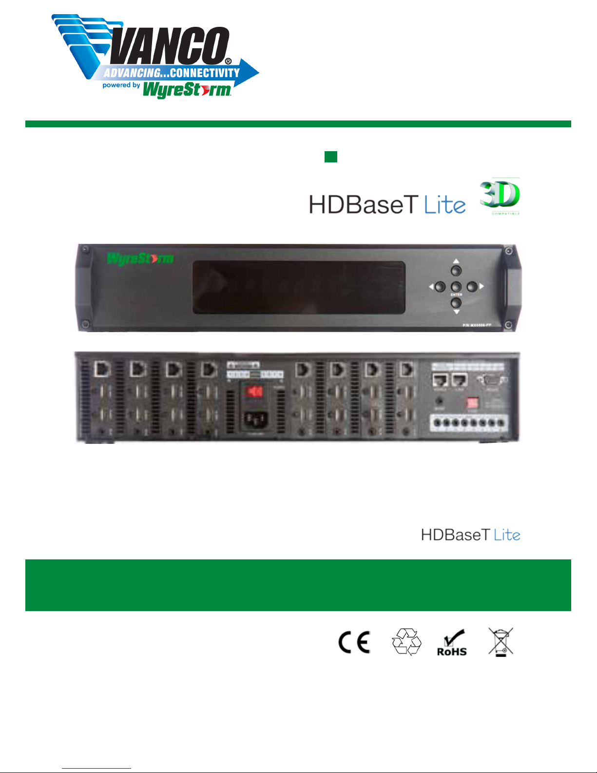
8x8 HDBaseT Lite Matrix
Part Number VPW-280771
8 Input 8 Output single cable matrix
with 2 way IR control

2
Contents 1. Introduction
CONTENTS AND INTRODUCTION
Technical Support: support@wyrestorm.com US: +866 677 0053 EU: +44 (0) 1793 230 343
The Wyrestorm PRO PLUS (PP) range uses a
2nd generation HDBaseT ‘Lite’ technology to sit
comfortably between our PRO range of matrices and
extenders and agship HDBaseT products to enable
the transmission of full, uncompressed HD 1080p
video and audio, with discrete 2-way IR control over
distances of up to 70m (131ft) using a single Cat5e/6/7
cable.
While HDBaseT is intended for high end, high spec
installations, HDBaseT Lite has been specically developed
for mid-range projects that perhaps do not necessitate the
such a high specication or indeed, a premium price tag.
HDBaseT Lite shares many of the same strengths as full
HDBT, such as a ‘one-cable’ distribution method, the same
signal stability and resistance to interference, but it removes
the Ethernet distribution and reduces signalling rate and
resolution, while still allowing fully controllable HD distribution
over single cable runs up to 70m (230ft).
Furthermore, as Wyrestorm systems are fully cascadable,
this 70m/230ft transmission range can be increased up to a
further 7 times by connecting to multiple HDBT Lite extender
sets for longer distributions.
Pro Plus matrices also include simultaneous HDMI outputs,
mirrored to the HDBT outputs to allow easy connection to
local devices such as AV receivers or additional, displays
to essentially double the number of outputs. Additionally,
duplicate HDMI also enables transmission over cable formats
other than Cat5e by using alternative Wyrestorm Extender
products such as Coax, Fibre or full HDBaseT for unrivalled
choice and compatibility.
The system offers exibility and reliability of signal distribution,
combined with innovative features and an ease of use to
deliver HD audio and video, controlled via IR, RS232 or LAN,
all on a single Cat5e/6/7 cable that removes the need for
additional control and video cables on installations, whether
in a residential or commercial setting.
The MX0606 / 0808-PP Pro Plus HDBaseT Lite Matrix
models allows any of their 6 or 8 HDMI inputs to be
distributed independently and simultaneously over distances
of up to 70m (230ft) to any of the 6 or 8 HD output displays
connected, regardless of HDCP encryption, with discrete IR
control.
For further information on this product and other Wyrestorm
ranges, visit our website or download our latest product
guide.
www.Wyrestorm.com
Introduction
Features
Safety Precautions
Package Contents
Front Panel Description
Rear Panel Description
Typical Application
Connection
Basic Operation
i. Front Panel Control
ii. Remote Control at Matrix end (Local IR) and Battery
Replacement
iii. Matrix System Code Switch – control two matrices with one
handset
iv. Remote Control at the Display End (Remote IR)
v. Handset Output/Source select Key Code
vi. IR call-back control of Matrix and Sources Devices
vii Two-way IR call-back control between Matrix, Sources and
Displays from Multiple Locations
viii. IR Extender Control
Advanced Remote Control
Advanced Operation
i. RS232 Control
ii. COM CTL – PC software Control
iii. NET CTL – LAN Control
iv. EDID DIP Switch settings
Troubleshooting
FAQ
Maintenance
Provided Service
Mail In Service
Installation Reference Log
Notes
Warranty
Warranty Limits and Exclusions
Specications
1
2
3
4
5
6
7
8
9
10
11
12
13
14
15
16
17
18
19
20
Part Number MX-0606-PP
Part Number MX-0808-PP

3
2. Features
3. Safety Precautions
FEATURES AND SAFETY PRECAUTIONS
Technical Support: support@wyrestorm.com US: +866 677 0053 EU: +44 (0) 1793 230 343
• Quick and easy installation – set up in seconds straight out of the box.
• Simplied ports - Input: HDMI – Output: Simultaneous HDMI and
integrated RJ45 connectors for a single Cat5e/6/7 UTP cable to each
display point for ease of installation*
* The inclusion of duplicate HDMI ports essentially doubles the
number of outputs (though slaved to the output channel on
the matrix), or allowing connection to Coax, Fibre or full HDBT
extender sets for increased exibility and length of distribution.
• Conforms to IEEE-568B standards.
• Each HDMI port also supports DVI signals.
• Enables up to 6 (MX0606-PP) and 8 (MX0808-PP) HDMI video/audio
devices to be independently switched through 6
(MX0606-PP) or 8 (MX0808-PP) HDMI displays or projectors for
uncompressed digital distribution.
• Each output able to show any connected source simultaneously
regardless of whether the input carries HDCP encryption.
• HDCP compliant with constant feed to prevent screen dropouts.
• Rened for Custom Install and Home Theatre Installations.
• Reads and copies EDID from connected devices with additional
EDID conguration through customisable DIP switch settings if
necessary.
• The same robust transmission technology as full HDBT that is far more
resistant to electrostatic interference than conventional
non-HDBT distribution.
• HDMI v1.4 with full 3D compatibility with frame packing/sequential
(Blu-Ray) and interlaced stereoscopic (satellite/cable broadcasts).
• Central RS232 control – fully compatible with all market leading control
systems with full integration protocols available for AMX, Control 4,
Crestron, Red Eye, Nevo, RTI, Control FX, Savant, BitWise.
• LAN control – with Control 4 TELNET protocols.
• Wide range, two way discrete IR control between source and display
and vice versa (30 KHz to 56 KHz frequency)
• 2K resolution (compared to 4k resolution with full HDBaseT).
• 36bit Deep Colour (compared to 48bit with Full HDBaseT, and 24bit
PRO).
• 6.75 Gbps bandwidth range/signalling rate (compared to
10.2Gbps with full HDBaseT).
• 70m (230ft) distance range of matrix/extenders – (compared to
100m/328ft HDBaseT or 50m/164ft PRO) can be lengthened by
connecting to multiple 70m extender sets or used with any other
Wyrestorm extenders, such as Coax, full HDBT or Fibre (distances
under perfect transmission conditions*)
• Each Output port can be fed to multiple displays (cascaded).
• Supports all high denition resolution
1. Do not expose this apparatus to rain, moisture,
sprays, drips or splashes and ensure that no
objects containing liquids are placed on the
apparatus, including cups, glasses and vases.
2. Do not place this unit in a conned space such as
enclosed shelving, cabinets or bookshelves.
Ensure the unit is adequately ventilated.
3. To prevent the risk of electric shock or re hazard
due to overheating, do not cover the unit or
obstruct ventilation openings with material,
newspaper, cardboard or anything that may restrict
airow into the unit.
4. Do not install near external heat sources such as
radiators, heat registers, boilers or any device that
produces heat such as ampliers or computers and
do not place near sources of naked ame.
5. Unplug apparatus from power supply during
lightening storms or when unused for long periods
of time.
6. Protect the power cable from being walked on,
pinched or restricted in any way, especially at plug
connections.
7. Only use attachments/accessories specied by the
manufacturer.
8. Units contain non-servicable parts - Refer all
servicing to qualied service personnel.
WARNING
To reduce the risk of re, electric shock
or product damage:
FEATURES AND SAFETY PRECAUTIONS
3. Safety Precautions
WARNING
To reduce the risk of fire, electric shock
or product damage:
• Protection against ESD (electrostatic discharge) included within
the unit to further stabilise transmission.
• LED indications for clear power and video signal selection.
• 5v mains supply included but receivers may be powered through the
USB port of the display using Wyrestorm USB to 5v power adaptor)
• Fully cascadable to further lengthen transmission.
*NOTE: ideal conditions denote cable run is within
specified distance range of product, no electrical
interference, the use of straight cable runs with no bends
or kinks and no patch panels or wall outlets used. Please
be advised that the presence of any of these factors in
your installation may compromise bandwidth and signal
strength. For longer transmission distances, RS232 control
and Ethernet pass-through, please see our full HDBaseT
or HDBT Lite range of matrices, transmitters, receivers and
extender sets.
USB to 5V Cable
Part Number
CAB-USB-5V
4
PACKAGE CONTENTS AND SPECIFICATIONS
4. Package Contents
5. Specication
• MX0606-PP / MX0808-PP main unit
• Printed instruction manual
• Flash USB stick containing PC control software and digital copy
of instruction manual*
*Downloadable manual can be found at www.wyrestorm.com
• Matrix mounting brackets
• 1 x 100~240V AC Power cable power supply
• 1 x IR Extension cable
• 1 x USB to UART cable
• 1 x RS232 to RS485 converter
• 6 / 8 x IR TX Emitters (small sensor for Input source)
• 6 / 8 x IR RX Emitters (larger sensor for Output display)
• 1 x Wyrestorm matrix remote control. (Battery not included)
Technical Support: support@wyrestorm.com US: +866 677 0053 EU: +44 (0) 1793 230 343
• MX0606-PP / MX0808-PP main unit
• Printed instruction manual
• Flash USB stick containing PC control software and digital copy
of instruction manual*
*downloadable versions can be found at www.wyrestorm.com
• Matrix mounting brackets
• 1 x 100~240V AC Power cable power supply
• 1 x IR Extension cable
4. Package Contents
• 1 x USB to UART cable
• 1 x RS232 to RS485 converter
• 6 / 8 x IR TX Emitters (small sensor for Input source)
• 6 / 8 x IR RX Emitters (larger sensor for Output display)
• 1 x Wyrestorm matrix remote control incl. battery (size/type:
CR2025 3V)
• 1 x stylus
5. Specifications
Output Video HDMI v1.4 with full 3D com-
patibility with Frame Sequen-
tial (Blu-ray) and Interlaced
Stereoscoptic (satellite/cable
broadcasts)
Audio Format Supported DTS-HD, Dolby True HD
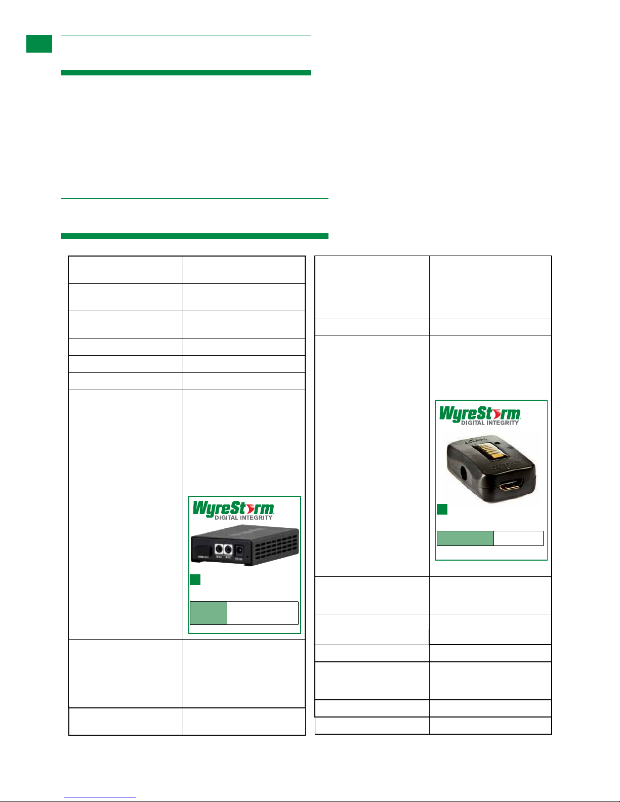
Max. Transmission distance
over HDMI
15m / 49ft – if a longer HDMI
connection is necessary, we
offer the Wyrestorm in-line
HDMI to HDMI coupler RP-
HD-HD.
Max. Transmission distance
over Cat5e/6/7
70m / 230ft – using
Wyrestorm RX-1UTP-IR-70
Display Receiver.
Power Consumption 35 Watts (max.)
Power Supply 100-240V AC
Dimensions 440mm / 17.3” (W)
42mm / 1.6” (H)
340mm / 13.4” (D)
Weight 6.7 Kg / 14.8lbs
Operating Temperature
Range
0 to +35°C (32 to +95°F)
Operating Humidity Range 5 to 90 % RH
(no condensation)
Output Bandwidth Signalling
Rate
6.75Gbps
Input Video Signal 0.5-1.0 volts p-p
Input DDC Signal 5 volts p-p (TTL)
Maximum Single Link Range 1080p Deep Colour
Transmission distance 1080p signal up to 70m /
230ft (Under perfect transmission conditions including
straight cable runs with no
electrical interference, bends,
kinks, patch panels or wall
outlets.) Using Wyrestorm RX1UTP-IR-70 Display receivers
behind each output display.
Video Format Supported VESA: 640x480, 800x600,
1024x768, 1280x1024,
1600x1200, 1920x1200
DTV/HDTV:
480i/576i/480p/576p/720p/
1080i/1080p
Single Cat5e/6/7
Display Receiver (70m)
Part
Number
RX-1UTP-IR-70
In-line HDMI to HDMI
coupler
Part Number
RP-HD-HD
• 1 x USB to UART cable
• 1 x RS232 to RS485 converter
• 6 / 8 x IR TX Emitters (small sensor for Input source)
• 6 / 8 x IR RX Emitters (larger sensor for Output display)
• 1 x Wyrestorm matrix remote control incl. battery (size/type:
CR2025 3V)
• 1 x stylus
Output Video HDMI v1.4 with full 3D com-
patibility with Frame Sequen-
tial (Blu-ray) and Interlaced
Stereoscoptic (satellite/cable
broadcasts)
Audio Format Supported DTS-HD, Dolby True HD
Max. Transmission distance
over HDMI
15m / 49ft – if a longer HDMI
connection is necessary, we
offer the Wyrestorm in-line
HDMI to HDMI coupler RPHD-HD.
Max. Transmission distance
over Cat5e/6/7
70m / 230ft – using
Wyrestorm RX-1UTP-IR-70
Display Receiver.
In-line HDMI to HDMI
coupler
Part Number
RP-HD-HD
HDMI v1.4 with full 3D compatibility with Frame Sequential (Blu-ray) and Stereoscoptic (satellite/cable broadcasts)
1080p 36bit Deep Colour
• 1 x USB to UART cable
• 1 x RS232 to RS485 converter
• 6 / 8 x IR TX Emitters (small sensor for Input source)
• 6 / 8 x IR RX Emitters (larger sensor for Output display)
• 1 x Wyrestorm matrix remote control incl. battery (size/type:
CR2025 3V)
• 1 x stylus
Output Video HDMI v1.4 with full 3D com-
patibility with Frame Sequen-
tial (Blu-ray) and Interlaced
Stereoscoptic (satellite/cable
broadcasts)
Audio Format Supported DTS-HD, Dolby True HD
Max. Transmission distance
over HDMI
15m / 49ft – if a longer HDMI
connection is necessary, we
offer the Wyrestorm in-line
HDMI to HDMI coupler RP-
HD-HD.
Max. Transmission distance
over Cat5e/6/7
70m / 230ft – using
Wyrestorm RX-1UTP-IR-70
Display Receiver.
Power Consumption 35 Watts (max.)
In-line HDMI to HDMI
coupler
Part Number
RP-HD-HD
70Watts max. (MX0606-PP)
60Watts max. (MX0808-PP)
• 1 x USB to UART cable
• 1 x RS232 to RS485 converter
• 6 / 8 x IR TX Emitters (small sensor for Input source)
• 6 / 8 x IR RX Emitters (larger sensor for Output display)
• 1 x Wyrestorm matrix remote control incl. battery (size/type:
CR2025 3V)
• 1 x stylus
Output Video HDMI v1.4 with full 3D com-
patibility with Frame Sequen-
tial (Blu-ray) and Interlaced
Stereoscoptic (satellite/cable
broadcasts)
Audio Format Supported DTS-HD, Dolby True HD
Max. Transmission distance
over HDMI
15m / 49ft – if a longer HDMI
connection is necessary, we
offer the Wyrestorm in-line
HDMI to HDMI coupler RP-
HD-HD.
Max. Transmission distance
over Cat5e/6/7
70m / 230ft – using
Wyrestorm RX-1UTP-IR-70
Display Receiver.
Power Consumption 35 Watts (max.)
Power Supply 100-240V AC
Dimensions 440mm / 17.3” (W)
42mm / 1.6” (H)
340mm / 13.4” (D)
Weight 6.7 Kg / 14.8lbs
In-line HDMI to HDMI
coupler
Part Number
RP-HD-HD
Audio Format Supported DTS-HD, Dolby True HD
Max. Transmission distance
over HDMI
15m / 49ft – if a longer HDMI
connection is necessary, we
offer the Wyrestorm in-line
HDMI to HDMI coupler RP-
HD-HD.
Max. Transmission distance
over Cat5e/6/7
70m / 230ft – using
Wyrestorm RX-1UTP-IR-70
Display Receiver.
Power Consumption 35 Watts (max.)
In-line HDMI to HDMI
coupler
Part Number
RP-HD-HD
• 1 x USB to UART cable
• 1 x RS232 to RS485 converter
• 6 / 8 x IR TX Emitters (small sensor for Input source)
• 6 / 8 x IR RX Emitters (larger sensor for Output display)
• 1 x Wyrestorm matrix remote control incl. battery (size/type:
CR2025 3V)
• 1 x stylus
Output Video HDMI v1.4 with full 3D com-
patibility with Frame Sequen-
tial (Blu-ray) and Interlaced
Stereoscoptic (satellite/cable
broadcasts)
Audio Format Supported DTS-HD, Dolby True HD
Max. Transmission distance
over HDMI
15m / 49ft – if a longer HDMI
connection is necessary, we
offer the Wyrestorm in-line
HDMI to HDMI coupler RP-
HD-HD.
Max. Transmission distance
over Cat5e/6/7
70m / 230ft – using
Wyrestorm RX-1UTP-IR-70
Display Receiver.
Power Consumption 35 Watts (max.)
Power Supply 100-240V AC
Dimensions 440mm / 17.3” (W)
42mm / 1.6” (H)
340mm / 13.4” (D)
Weight 6.7 Kg / 14.8lbs
In-line HDMI to HDMI
coupler
Part Number
RP-HD-HD
Rack Space Required 2U
• 1 x USB to UART cable
• 1 x RS232 to RS485 converter
• 6 / 8 x IR TX Emitters (small sensor for Input source)
• 6 / 8 x IR RX Emitters (larger sensor for Output display)
• 1 x Wyrestorm matrix remote control incl. battery (size/type:
CR2025 3V)
• 1 x stylus
Output Video HDMI v1.4 with full 3D com-
patibility with Frame Sequen-
tial (Blu-ray) and Interlaced
Stereoscoptic (satellite/cable
broadcasts)
Audio Format Supported DTS-HD, Dolby True HD
Max. Transmission distance
over HDMI
15m / 49ft – if a longer HDMI
connection is necessary, we
offer the Wyrestorm in-line
HDMI to HDMI coupler RP-
HD-HD.
Max. Transmission distance
over Cat5e/6/7
70m / 230ft – using
Wyrestorm RX-1UTP-IR-70
Display Receiver.
Power Consumption 35 Watts (max.)
Power Supply 100-240V AC
Dimensions 440mm / 17.3” (W)
42mm / 1.6” (H)
340mm / 13.4” (D)
Weight 6.7 Kg / 14.8lbs
In-line HDMI to HDMI
coupler
Part Number
RP-HD-HD
BTU Rating 238.7 (MX0606-PP)
204.6 (MX0808-PP)
70Watts max. (MX0606-PP)
60Watts max. (MX0808-PP)
5
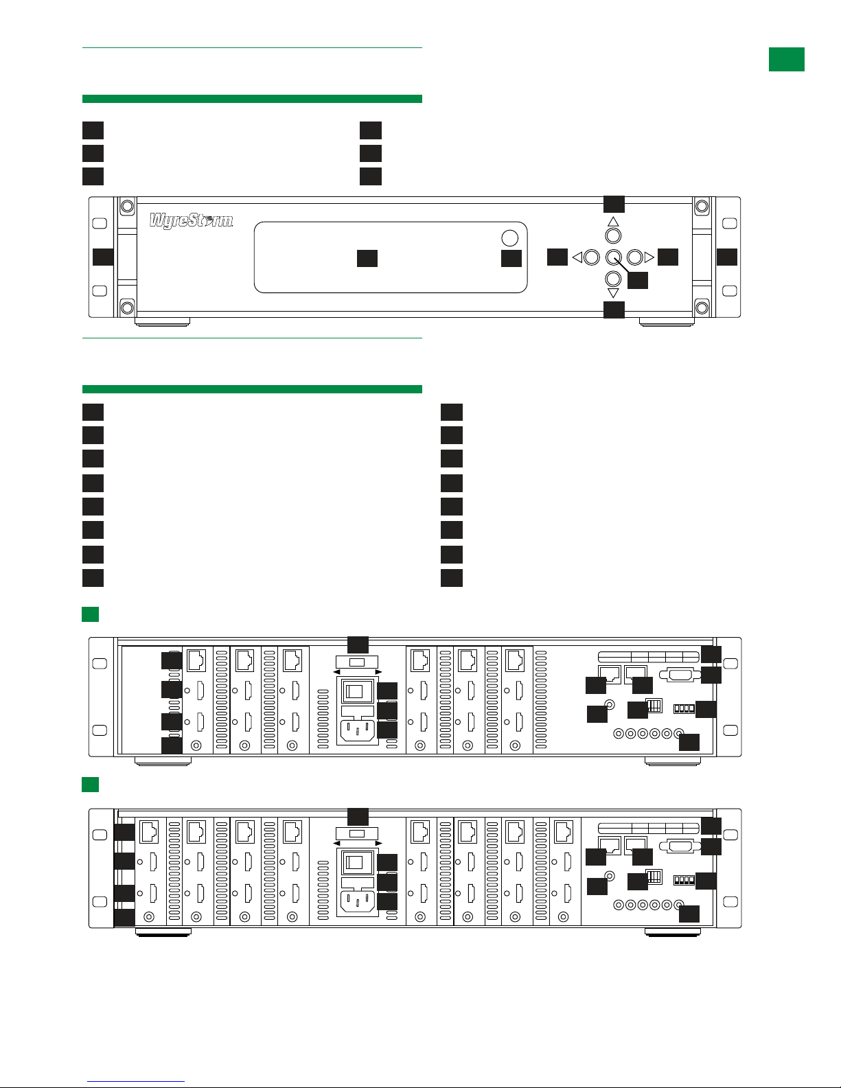
6. Front Panel
7. Rear Panel
FRONT PANEL AND REAR PANEL
RS232 and LAN ports are for matrix control. Ensure crossover UTP cable is used to connect the LAN directly to a
computer or server, and a direct/straight through connection is used to connect via a router/switch. Connection
will fail if the incorrect cable is used.
1
1
4
2
2
5
7
3
3
6
8
4
9
12
5
10
13
15
6
11
14
16
EDIDIR EXT
IR RXH DMI OUT HDBT OUTHDMI IN
IR RXH DMI OUT HDBT OUTHDMI IN
IR RXH DMI OUT HDBT OUTHDMI IN
IR RXH DMI OUT HDBT OUTHDMI IN
IR RXH DMI OUT HDBT OUTHDMI IN
IR RXH DMI OUT HDBT OUTHDMI IN
IR TX
123456
RS485 RS232LAN
1 2 3GROUP4 5 6
RJ45 + RS285 DEFINITION
RJ45 PIN 1 2 7 8
DESCRIPTION TX+ TX- RX+ RX-
DEFAULT
1
1
0
ON
OFF
23 4
5
7
6
8
9
12
1
4
10
13
15
2
11
14
16
3
EDIDIR EXT
IR RX HDMI OUT HDBT OUTHDMI IN
IR RX HDMI OUT HDBT OUTHDMI IN
IR RX HDMI OUT HDBT OUTHDMI IN
IR RX HDMI OUT HDBT OUTHDMI IN
IR RX HDMI OUT HDBT OUTHDMI IN
IR RX HDMI OUT HDBT OUTHDMI IN
IR TX
123456
RS485 RS232LAN
IR RX HDMI OUT HDBT OUTHDMI IN
IR RX HDMI OUT HDBT OUTHDMI IN
1 2 3GROUP4 5 6
RJ45 + RS285 DEFINITION
RJ45 PIN 1 2 7 8
DESCRIPTION TX+ TX- RX+ RX-
DEFAULT
1
1
0
ON
OFF
23 4
5
7
6
8
9
12
1
4
10
13
15
2
11
14
16
3
LED Input/Output Select Screen
HDBT Output ports (RJ45 Cat5e/6/7)
IR Receiver port (IR RX)
Output Select Buttons (Left/Right)
RS485 port
RS232
IR Receive Window
Duplicate HDMI Output ports (mirrors HDBT Outputs)
AC 100 – 240V power input
Power switch
Enter Selection Buttons
LAN port
IR Extension port (IR EXT)
EDID switch default diagram
Input Select Buttons (UP/DOWN)
HDMI Input ports
Fuse (lift cover to replace)
Input/Output port grouping indicator
Rack Brackets
RJ45 to RS485 denition indicator
EDID DIP Switch (for manual EDID setting)
IR TX Receiver ports (corresponds to input ports)
Technical Support: support@wyrestorm.com US: +866 677 0053 EU: +44 (0) 1793 230 343
ENTER
1
2
3
3
44 66
5
Part Number MX-0606-PP
Part Number MX-0808-PP
6
Apple
TV/Media
Server
Cable/Satellite
PS3/Xbox
Blu-ray/DVD
Apple TV/Media Server
PS3/Xbox
Blu-ray/DVD
RX-1UTP-IR-70
Output 01Mirror of 01
70m/230ft
RX-1UTP-IR-70
Output 02Mirror of 02
70m/230ft
RX-1UTP-IR-70
Output 03Mirror of 03
70m/230ft
RX-1UTP-IR-70
Output 04Mirror of 04
70m/230ft
RX-1UTP-IR-70
Output 05Mirror of 05
70m/230ft
RX-1UTP-IR-70
Output 06Mirror of 05
70m/230ft
RX-1UTP-IR-70
Output 07Mirror of 07
70m/230ft
RX-1UTP-IR-70
Output 08Mirror of 08
70m/230ft
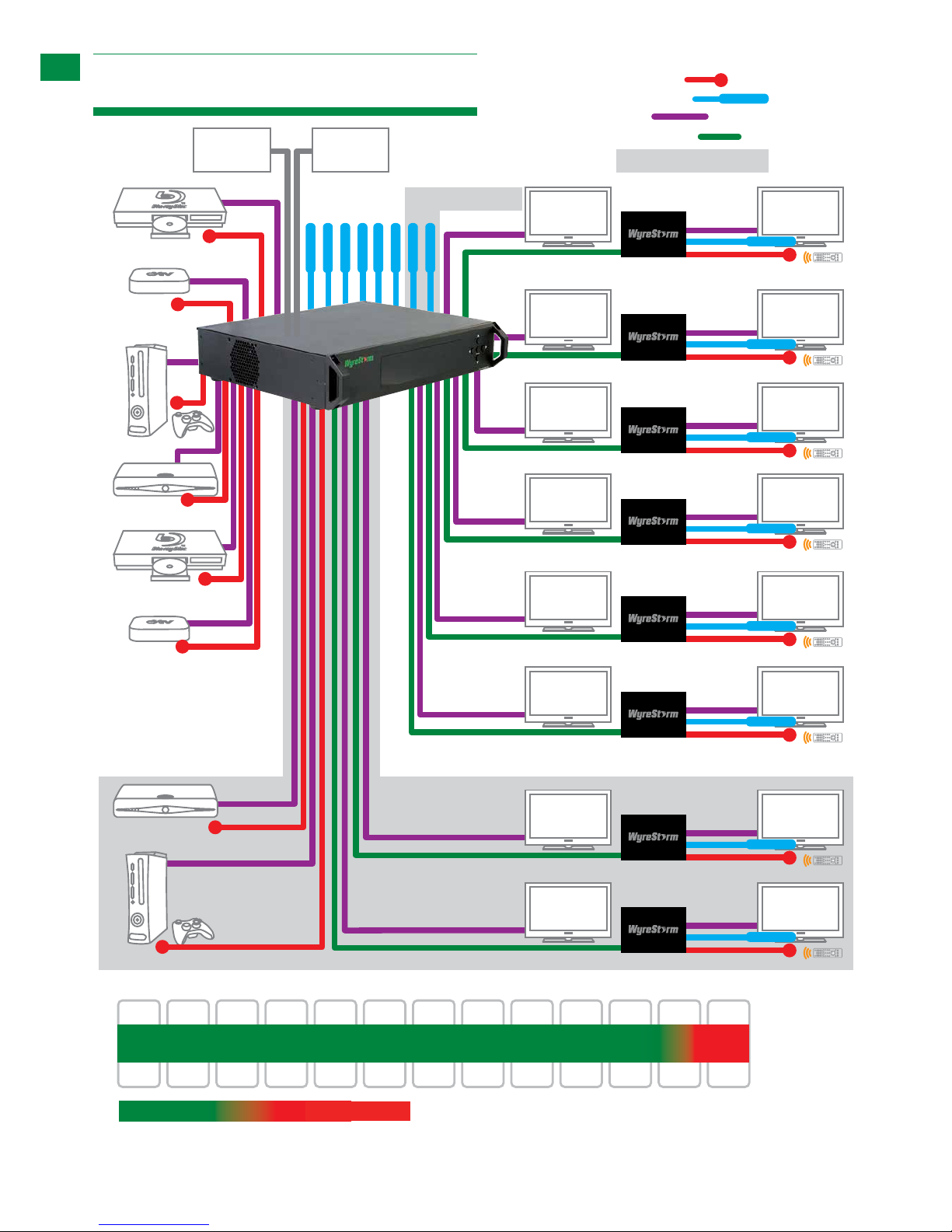
49ft32ft16ft 65ft 82ft 98ft 114ft 131ft147ft 164ft 196ft 229ft 262ft
15m10m5m 20m 25m 30m 35m 40m 45m 50m 60m 70m 80m
1080p 1080i
HDBaseT Lite range 1080p
MX0606-PP / MX0808-PP with RX-1UTP-IR70 display receiver
Cat 5e/6 cable performance
MX0808-PP only
Cable/Satellite
MX0808-PP only
Control
System
Power
KEY
IRTX Emitter
IRRX Receiver
HDMI
UTP Cat5e/6/7
MX0808-PP only
8.
Typical Application
Technical Support: support@wyrestorm.com US: +866 677 0053 EU: +44 (0) 1793 230 343
TYPICAL APPLICATION
8. Typical Application
signal cut out
7
Technical Support: support@wyrestorm.com US: +866 677 0053 EU: +44 (0) 1793 230 343
9. Connection
TYPICAL APPLICATION
Connection
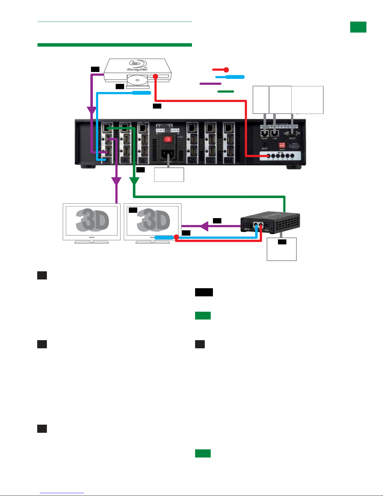
Control System
(Additional
control via
RS232)
Connection
9. Connection
5V mains or
USB power
adapter
07
RS232 to
display
(optional)
Display 1 Mirror
Duplicate HDMI
Display 1
HDMI Source
IR TX emitter placed securely
over input device infrared
sensor window
IR RX jack plugged into
IR RX port of matrix with
receiver placed in clear
sight of remote control
Cat 5e/6/7 (up to 70m 230ft)
01
02
03
04
05
06
KEY
IRTX Emitter
IRRX Receiver
HDMI
UTP Cat5e/6/7
Control System
(Additional
control via
RS232)
LANRS485
08
IR RX receiver and IR TX emitter
placed discretely on the display with a
clear line of sight to the remote
handset being used
optional
Power
Connection
9. Connection
HDMI Source
IR TX emitter placed securely
over input device infrared
IR RX jack plugged into
IR RX port of matrix with
receiver placed in clear
01
02
03
KEY
IRTX Emitter
IRRX Receiver
HDMI
UTP Cat5e/6/7
Control System
(Additional
control via
RS232)
LANRS485
optional
Connection
Control System
(Additional
control via
RS232)
TELNET
Connection
5V mains or
USB power
adapter
07
RS232 to
display
(optional)
Control System
(Additional
control via
RS232)
LANRS485
optional
Connect each HDMI input source (such as: HD-
DVD, PS3/, XBOX360, satellite/cable, Blu-Ray etc.) to the
HDMI inputs of the MATRIX.
Attention Do Not Hotswap plugs! - Please
insert and extract cables carefully with the power
SWITCHED OFF. Connecting and disconnecting
while powered can result in damage to circuitry.
Attach the IR TX emitters directly over the infrared
receiving sensor of each input source using the adhesive
backing. You may need to adjust the position of the
emitter after installation to achieve the best results.
Sometimes moving the sensor to different areas of the
source facia can improve IR performance.
Plug the 3.5mm jack of the IR TX emitter into the
corresponding number IR TX port on the rear panel of the
MATRIX.
For two-way IR controlling the display from the
matrix side: Plug the 3.5mm jack of the IR RX receiver
into the corresponding IR RX port on the rear panel of the
MATRIX, ensuring the receiver is placed in clear view to
receive an IR signal.
NOTE Make sure the IR jacks are in the same
number ports.
HINT Locate the infrared sensor on devices by
shining a flashlight onto the display panel of
sources and look for a small sensor.
Connect a good quality, well terminated Cat 5e/6/7
cable with an RJ45 connector wired to 568B standard at
both ends from the HDBT Output port of the MATRIX to
the UTP IN of the RX-1UTP-IR-70 DISPLAY RECEIVER
(or, if using another Wyrestorm extender set, connect the
transmitter to the matrix via the HDMI OUT port)
Ensure both RJ45 connectors are pushed securely into
each port and supported by the connector strain relief
clip to prevent them from becoming loose. The quality
of termination for your RJ45 is essential. Poor quality
terminations lead to intermittent performance and longer
install times.
HINT Although all Wyrestorm products are tested
1
4
2
3
8
Technical Support: support@wyrestorm.com US: +866 677 0053 EU: +44 (0) 1793 230 343
using Cat5e as standard, we suggest using Cat6 as
the preferred cable due to its improved transmission
capabilities.
If using a Duplicate display mirrored to the HDBT Output,
connect the display via the HDMI OUT port.
ATTENTION We strongly recommend using the
supplied mounting brackets to secure the MATRIX
and the accompanying TRANSMITTER & DISPLAY
RECEIVER baluns. Any sudden movement of these
devices could lead to loss of picture and sound if
connections become loose or strained, resulting in
unnecessary service call backs.
Connect the HDMI OUT of the DISPLAY RECEIVER
to the HDMI IN of the display.
Plug the 3.5mm jack of the IR RX receiver into the
IR RX port of the display receiver balun. Place the IR RX
receiver sensor discretely on the front of the display with
care taken to achieve a clear line of sight with the remote
control to be used.
For two-way IR controlling the display from the matrix
end: Plug the 3.5mm jack of the IR TX emitter into the
corresponding IR TX port on the display receiver, ensuring
the emitter is placed directly over the infra-red receiving
sensor of the display using the adhesive backing.
Again, adjustment of receiver and emitter position may be
needed to achieve the best IR signal distribution.
After ensuring the display receiver
balun is fixed firmly in place behind the
display, insert the 5v mains power adaptor
(included) or connect the USB to 5v
power cable.
Switch on the power to your input sources, displays,
and any display receivers used.
Finally, switch on the matrix at the rear and your
Wyrestorm system should now be fully connected and
ready for use.
ATTENTION Remember, always switch off the matrix
before unplugging any inputs or outputs – follow
last on, first off protocol.
If your IR emitters and receivers are correctly placed you
should now be able control both sources and displays
discretely from either location.
ATTENTION If there is electrical interference or
cable bends/kinks within the set up the IR is one of
the first functions to fail.
If you do not have IR control:
• Check your cables are straight with jacks firmly
connected to ports.
• Check your IR sensors are unobstructed and able to
receive infrared signals.
• Check direct sunlight on the emitters/receivers is not
affecting the infrared signal.
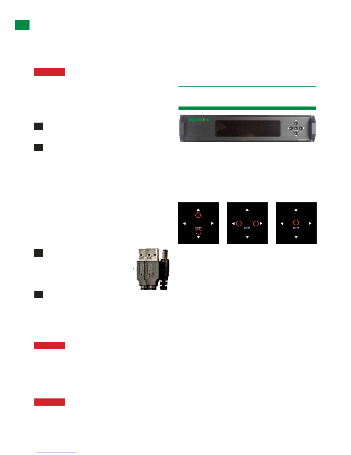
The Wyrestorm MX0606/0808-PP is designed with ease
of set-up and use in mind. Basic switching of source
inputs to output displays can be achieved via the front
panel control of the matrix.
On power up, the front panel will flash as the matrix
initialises. When the display stops flashing, the matrix is
ready to use.
OUTPUT selection INPUT selection Confirm
OUTPUTS/INPUTS
OUTPUTS are selected by pressing the LEFT and
RIGHT arrow buttons to scroll forwards and backwards
numerically through the displays connected to the matrix.
The corresponding OUTPUT channel number will blink on
the display when reached.
Likewise, the UP and DOWN arrow buttons scroll
numerically through any INPUT sources connected to
the system. When the desired OUTPUT and INPUT is
reached, push the ENTER button to confirm the selection.
The display will stop blinking to let you know the matrix
has been set.
Repeated pressing of the select button of a specific
output scrolls numerically through the HDMI input devices
connected to the matrix, with the corresponding LEDs
illustrating when a device has been selected for that
particular output. The chosen input will automatically
store for the output so, even when the matrix is powered
off and on, the last selected input/output combination will
remain.
5
7
6
8
10. Basic Operation
TYPICAL APPLICATION, BASIC OPERATION
9
Technical Support: support@wyrestorm.com US: +866 677 0053 EU: +44 (0) 1793 230 343
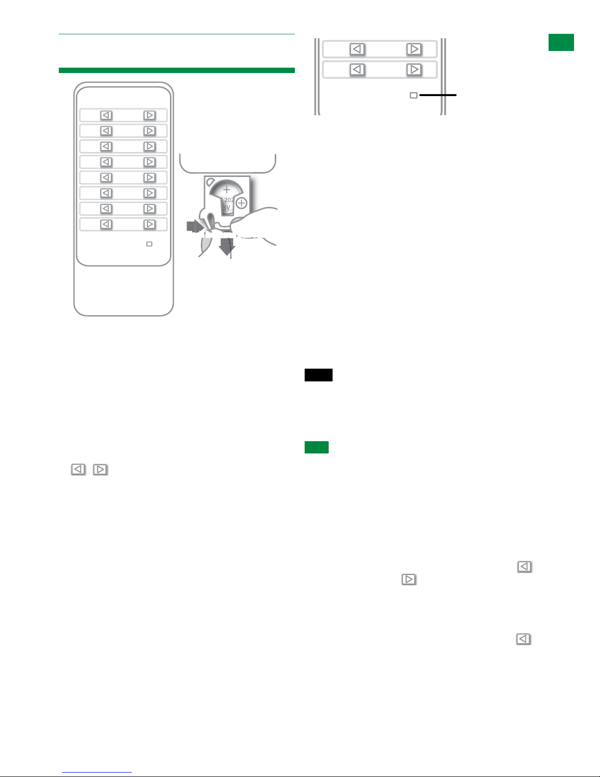
11. Basic Remote Control
The same basic switching functions can also be accessed
via the remote control.
Operation of the handset is the same regardless of
location – locally (source/IR emitter) or remotely (display/
IR receiver).
Simply toggle through the INPUT sources connected to
the matrix by pressing the left/right arrow buttons in each
numbered OUTPUT section on the handset.
Previous / next buttons
When using the remote control locally, i.e. pointed directly
at the matrix, the previous / next buttons are used to
scroll between the input sources connected to the matrix
for each individual output display. So for example, using
the previous / next buttons for 1 allows you to select the
source to be set to display 1 manually.
See below:
Matrix System Code Switch
The MX0606/0808-PP features an intuitive IR ‘Call Back’
system of control through which the matrix is able to
distinguish where the remote handset is being used to
change INPUTS and OUTPUTS and is able to switch
accordingly depending on the user’s location.
As such, the function of the handset buttons and
operation differs depending on where the handset is being
used.
In the event that two MX0606/0808-PP units are used
within close proximity, the matrix is capable of switching
between two distinct IR System Codes to allow control of
either matrix individually via the same hand-set.
Changing the System Code of the handset to that
assigned to a specific matrix will allow IR commands to
be delivered to only that unit.
The default system setting is 0x00 to control one matrix,
but pressing the SYSTEM CODE button on the handset
THREE TIMES rapidly activates the alternative Matrix
SYSTEM CODE 0x4e, allowing independent control of
a second unit. Pressing the button three times again to
reverts back to default 0x00 setting.
NOTE Changing the System Code is only necessary
if you are using two units within close range of the
IR signal. If using in different parts of the same
room it is likely that you will not need to change the
setting.
HINT If your remote control is not working, before
changing the battery, try changing the System Code
on the handset in case it has accidentally been
switched to an alternative matrix control mode
Remote Control at the Display End (Remote IR)
When controlling the matrix remotely from the display
side, the matrix automatically detects which particular
output location the user is at and only allows the selection
of sources 1-8 for that particular location using the
button - the right hand button will be deactivated.
For example, if you are in the Master Bedroom with
a display connected to output 3 of the matrix, the
output zone is automatically detected so options 1-8
will correspond to sources 1-8 on the matrix. Press
buttons 1-8 to scroll through your options as you would
channels on a regular TV remote.
BASIC REMOTE CONTROL
11. Basic Remote Control
OUTPUT
CHANNEL
INPUT SELECT
1
2
3
4
5
6
7
8
To change handset battery
Pinch here and pull out
Install battery ‘+’ side
up and only use CR
2025 3V batteries. Slide
compartment back into
the handset.
OUTPUT
CHANNEL
INPUT SELECT
1
2
3
4
5
6
7
8
System Code Switch
The default system setting is 0x00 to control one matrix, but
pressing the SYSTEM CODE button on the handset THREE
TIMES rapidly activates the alternative Matrix SYSTEM CODE
0x4e, allowing independent control of a second unit. Pressing the
button three times again to reverts back to default 0x00 setting.
NOTE
Changing the System Code is only necessary if you
are using two identical units within close range of the IR
signal. If using in different parts of the same room it is likely
that you will not need to change the setting.
HINT
If your remote control is not working, before changing the
battery, try changing the System Code on the handset in case it
has accidentally been switched to an alternative matrix control
mode.
Remote Control at the Display End (Remote IR)
When controlling the matrix remotely from the display side, the
BASIC REMOTE CONTROL
System Code Switch
INPUT SELECT
BASIC REMOTE CONTROL
System Code Switch
INPUT SELECT
BASIC REMOTE CONTROL
System Code Switch
INPUT SELECT
BASIC REMOTE CONTROL
BASIC REMOTE CONTROL
OUTPUT
CHANNEL
INPUT SELECT
1
2
3
4
5
6
7
8
System Code Switch
Install battery ‘+’ side up
and only use a CR2025 3v
battery. Slide compartment
back into the handset.
BASIC REMOTE CONTROL
10
Technical Support: support@wyrestorm.com US: +866 677 0053 EU: +44 (0) 1793 230 343
IR Call-back of Matrix and Source Devices
The Wyrestorm MX0606/0808-PP is not only a switcher
and extender of multiple HDMI signals to multiple HDMI
receivers located remotely, it also passes IR control
signals through the IR call-back system to the matrix
and HDMI sources for full, independent control of all
connected inputs from output locations.
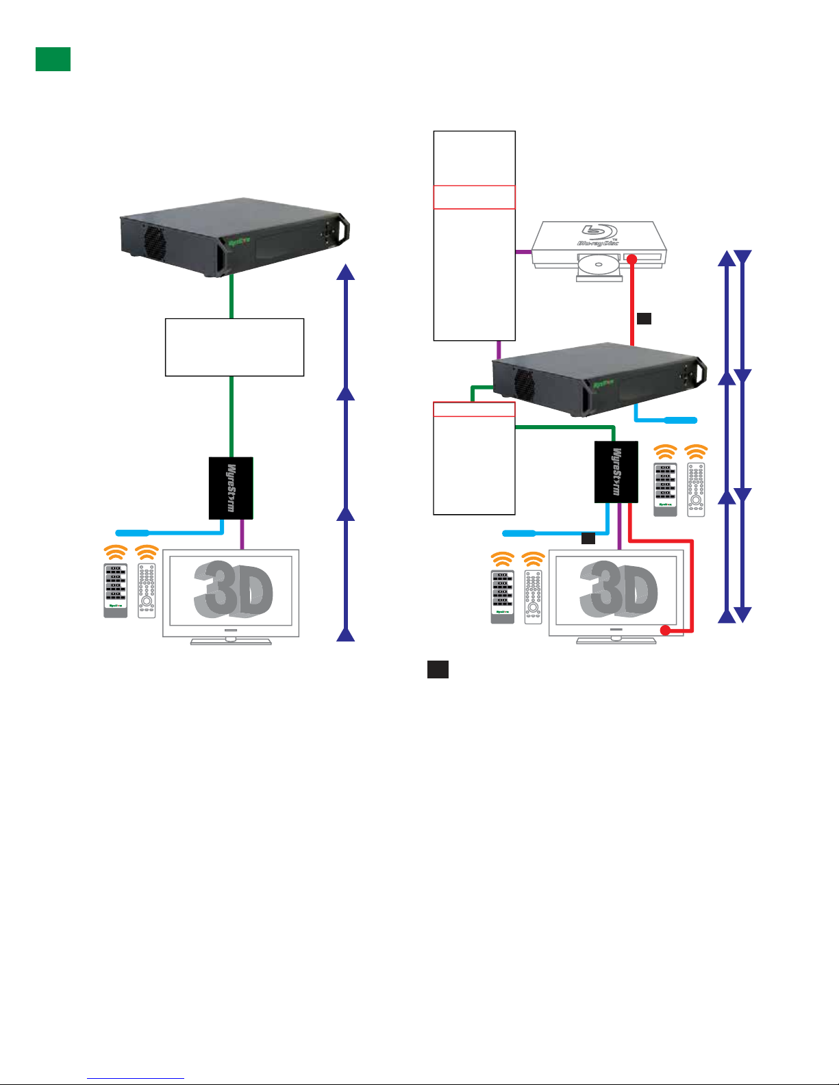
Two-way IR Call-back Between Matrix, Sources and
Displays from Multiple Locations
A key feature on our HDBaseT Lite Matrix range is
discrete IR control of the matrix, sources and displays
from any location – so inputs at the matrix end can be
controlled at a display location and displays can be
controlled at the matrix location.
This is accomplished by placing a series of IR Emitters on
devices to control and Receivers at all locations you wish
to control from to enable the IR signal to travel both ways
via the single Cat5e/6/7 cable.
The sequence of IR TX numbers correspond to the HDMI
INPUTS so when an OUTPUT selects a certain INPUT,
the CALL-BACK IR signal of that RJ45 port selects the
relevant IR TX port to OUTPUT the control signal.
Example: If OUTPUT 1 selects INPUT 3, the CALL-BACK
IR signal of that RJ45 OUTPUT links INPUT 3 with IR TX3
for the signal to be combined and communicated for that
input to be controlled remotely.
At Matrix end: Insert the 3.5mm jacks of the IR TX
Emitters included with the unit into the IR TX Emitter ports
at the rear of the matrix according to input. The IR signal
is added to the HDMI of the input device so, for example,
if the user is watching Blu-ray on input 3, the IR signal
will be directed through the IR TX3 socket to control the
device.
BASIC REMOTE CONTROL
IR Call-back of Matrix and Source Devices
The Wyrestorm MX0606/0808-PP is not only a switcher and
extender of multiple HDMI signals to multiple HDMI receivers
located remotely, it also passes IR control signals through the
IR call-back system to the matrix and HDMI sources for full,
independent control of all connected inputs from output locations.
Two-way IR Call-back Between Matrix, Sources and
Displays from Multiple Locations
A key feature on our HDBaseT Lite Matrix range is discrete IR
control of the matrix, sources and displays from any location – so
inputs at the matrix end can be controlled at a display location and
displays can be controlled at the matrix location.
This is accomplished by placing a series of IR Emitters on devices
to control and Receivers at all locations you wish to control from to
enable the IR signal to travel both ways via the single Cat5e/6/7
cable.
The sequence of IR TX numbers correspond to the HDMI INPUTS
so when an OUTPUT selects a certain INPUT, the CALL-BACK
IR signal of that RJ45 port selects the relevant IR TX port to
OUTPUT the control signal.
Example: If OUTPUT 1 selects INPUT 3, the CALL-BACK IR
signal of that RJ45 OUTPUT links INPUT 3 with IR TX3 for the
signal to be combined and communicated for that input to be
controlled remotely.
IR Path IR PathIR Path
IR Receiver
1 2 3 4
1
1 2 3 4
2
1 2 3 4
3
1 2 3 4
4
HDBT OUT 1
HDBT OUT 2
HDBT OUT 3
HDBT OUT 4
HDBT OUT 5
HDBT OUT 6
HDBT OUT 7
HDBT OUT 8
Single Cat5e/6/7
70m/230ft
Display
Reciever
HDMI Source
HDMI Cable
IR TX Receiver
HDMI Input 1
IR TX 1
HDMI Input 2
IR TX 2
HDMI Input 3
IR TX 3
HDMI Input 4
IR TX 4
HDMI Input 5
IR TX 1
HDMI Input 6
IR TX 2
HDMI Input 7
IR TX 3
HDMI Input 8
IR TX 4
01
Two-way IR Call-back Between Matrix, Sources and
Displays from Multiple Locations
A key feature on our HDBaseT Lite Matrix range is discrete IR
control of the matrix, sources and displays from any location – so
inputs at the matrix end can be controlled at a display location and
displays can be controlled at the matrix location.
This is accomplished by placing a series of IR Emitters on devices
to control and Receivers at all locations you wish to control from to
enable the IR signal to travel both ways via the single Cat5e/6/7
cable.
The sequence of IR TX numbers correspond to the HDMI INPUTS
so when an OUTPUT selects a certain INPUT, the CALL-BACK
IR signal of that RJ45 port selects the relevant IR TX port to
OUTPUT the control signal.
Example: If OUTPUT 1 selects INPUT 3, the CALL-BACK IR
signal of that RJ45 OUTPUT links INPUT 3 with IR TX3 for the
signal to be combined and communicated for that input to be
controlled remotely.
HDMI Source
HDMI Cable
IR TX Receiver
IR RX Receiver
Cat5e/6/7 up to
70m (230ft)
HDMI Input 1
IR TX 1
HDMI Input 2
IR TX 2
HDMI Input 3
IR TX 3
HDMI Input 4
IR TX 4
HDMI Input 5
IR TX 1
HDMI Input 6
IR TX 2
HDMI Input 7
IR TX 3
HDMI Input 8
IR TX 4
IR RX Receiver
IR TX Emitter
1 2 3 4
1
1 2 3 4
2
1 2 3 4
3
1 2 3 4
4
IR Path I R PathIR Path
UTP Out 1
UTP Out 2
UTP Out 3
UTP Out 4
UTP Out 5
UTP Out 6
UTP Out 7
UTP Out 8
1 2 3 4
1
1 2 3 4
2
1 2 3 4
3
1 2 3 4
4
01
02
1
1
2
 Loading...