

VANCO 280745 User Manual

PRODUCT MANUAL
Part Number: 280745
IR Distribution Over Coax Instruction Manual
DEAR CUSTOMER
Thank you for purchasing this product.
For optimum performance and safety, please read these instructions carefully before connecting, operating or adjusting this product. Please keep this manual for future
reference. 1 Year Warranty.
FEATURES:
• Allows for the Transmission of IR signals over Coaxial Cable, creating
an IR system with existing wiring
• In-Wall IR Receiver works in most lighting environments, including CFL
• IR Receive Frequency: 34 kHz to 60 kHz
• IR Transmit Frequencies: 38 kHz & 56 KHz
• Range: 40 ft @ 38 KHz & 25 ft @ 56 KHz
• Power Supply, 12VDC
• Blue IR conrmation LED light
IR repeating concepts
IR repeating allows the user to control devices which are not with in the
direct line of sight of the remote control. This is most commonly used in distributed
audio/video systems where the source components are centrally located.
SPECIFICATIONS
Receive Frequency Range......................... 34 kHz to 60 kHz
Transmit Frequencies.............................. 38 kHz & 56 KHz Range,
40ft. @ 38 KHz, 25ft. @ 56 KHz
Power.................................................... 12VDC, 30mA max.
Dimensions………..………..................... 45L x 14W x 13H mm
Cord Length………................................. 10ft (3m)
Connector Type……................................ 1/8” (3.5mm) TRS mini plug
Weight……………...…………………….. 28 g
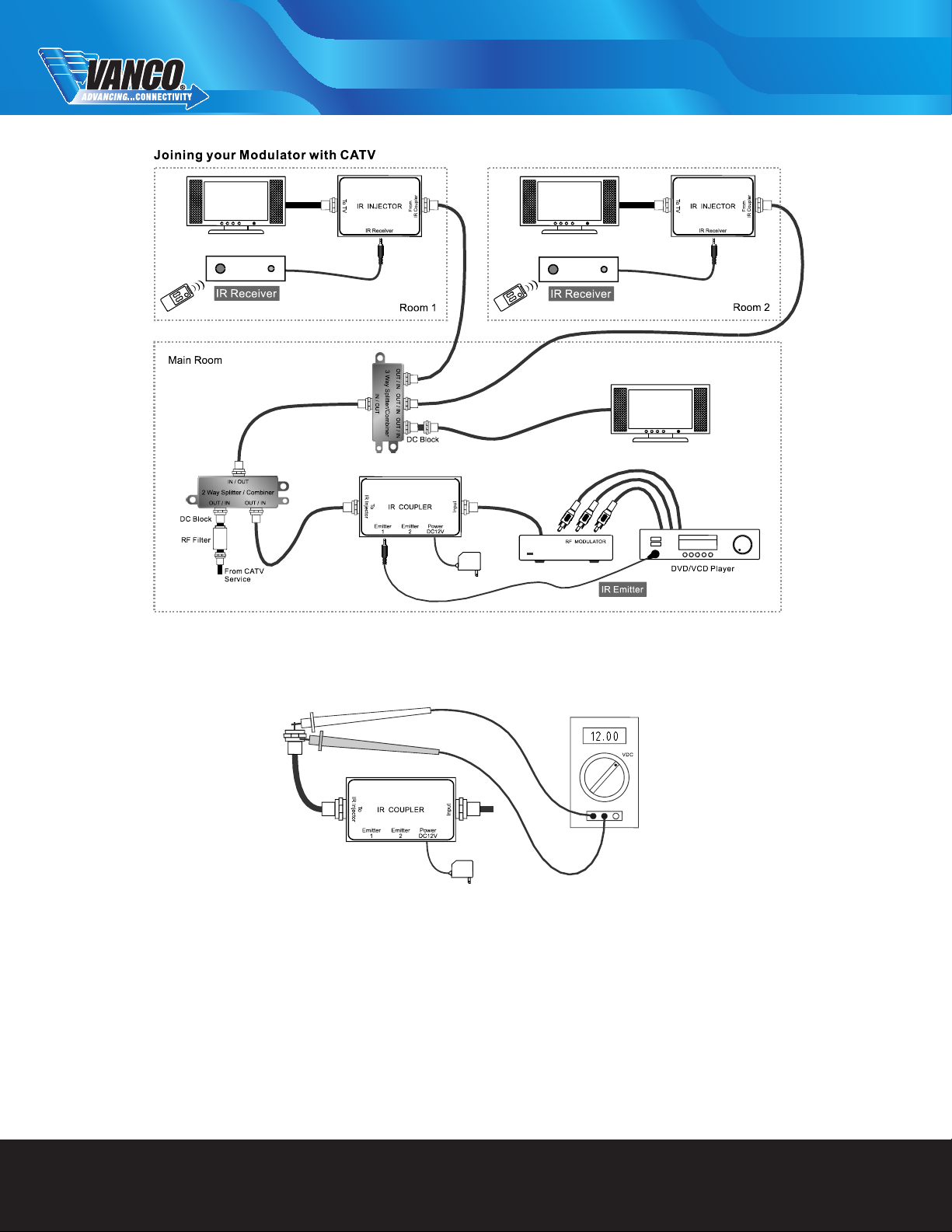
Basic IR Setup
A basic IR system is often used when an audio/video signal is distributed to a remote TV
location using an RF modulator. The IR INJECTOR is located near the TV, providing a
connection for an IR receiver, and the IR COUPLER is located near the audio/video
source, providing an IR emitter output
TECHNICAL SUPPORT
www.vanco1.com 800.626.6445
TROUBLESHOOTING
If your IR system is not working, check to see if IR COUPLER is feeding at least approximately 12 Volts DC onto the coax between the shield and center pin. (Any voltage
between 8-12 VDC is OK). If there is no voltage between the center pin and shield, check the connectors on each end of the coax.
If you are troubleshooting a whole-house IR system and you measure approximately 8-12 Volts DC on the output of the IR COUPLER, but 0 Volts DC on the output of your
RF splitter, check the following items:
1. Make sure you are using a DC passing splitter. Traditional splitters will short out DC voltage traveling on the coax and prevent your IR system from working.
2. Make sure that there are DC blocks on any output from the RF splitter that will not be connected to an IR INJECTOR. If outputs from the splitter are connected
directly to TV sets without going through a IR INJECTOR or DC block, the system voltage will be shorted out by the input of the TV set.
3. Double check the ttings at the end of your coax cables. If a little bit of shielding is touching the center pin, the voltage will be shorted out and the system will not
work.
4. The IR COUPLER has a current limiting circuit. If the IR COUPLER is shorted (due to a bad connection or an on-DC passing splitter) nothing will be harmed.
TECHNICAL SUPPORT
www.vanco1.com 800.626.6445
 Loading...