

Page 1
OPERATION AND MAINTENANCE INSTRUCTIONS
FOR
BLAST PAK
PACKAGED COMPRESSED AIR TREATMENT SYSTEM
MODELS: FD-400 through FD-1600
WARNING
DO NOT OPERATE THIS SYSTEM ABOVE MAXIMUM WORKING
PRESSURE (MWP) AND/OR MAXIMUM OPERATING
TEMPERATURE (
PLATE.
THIS ASME CODE VESSEL MUST BE PROTECTED BY A
PRESSURE RELIEF VALVE. Refer to OSHA 1910.169 Par. b,
Sub. Par (3) and ASME Boiler and Pressure Vessel Code,
Section VIII, Division 1, UG-125 through UG-136. Also comply
with all applicable state and local codes.
O
F) SHOWN ON THE VESSEL ASME DATA
JANUARY 2006
P/N 32-0282 rev A
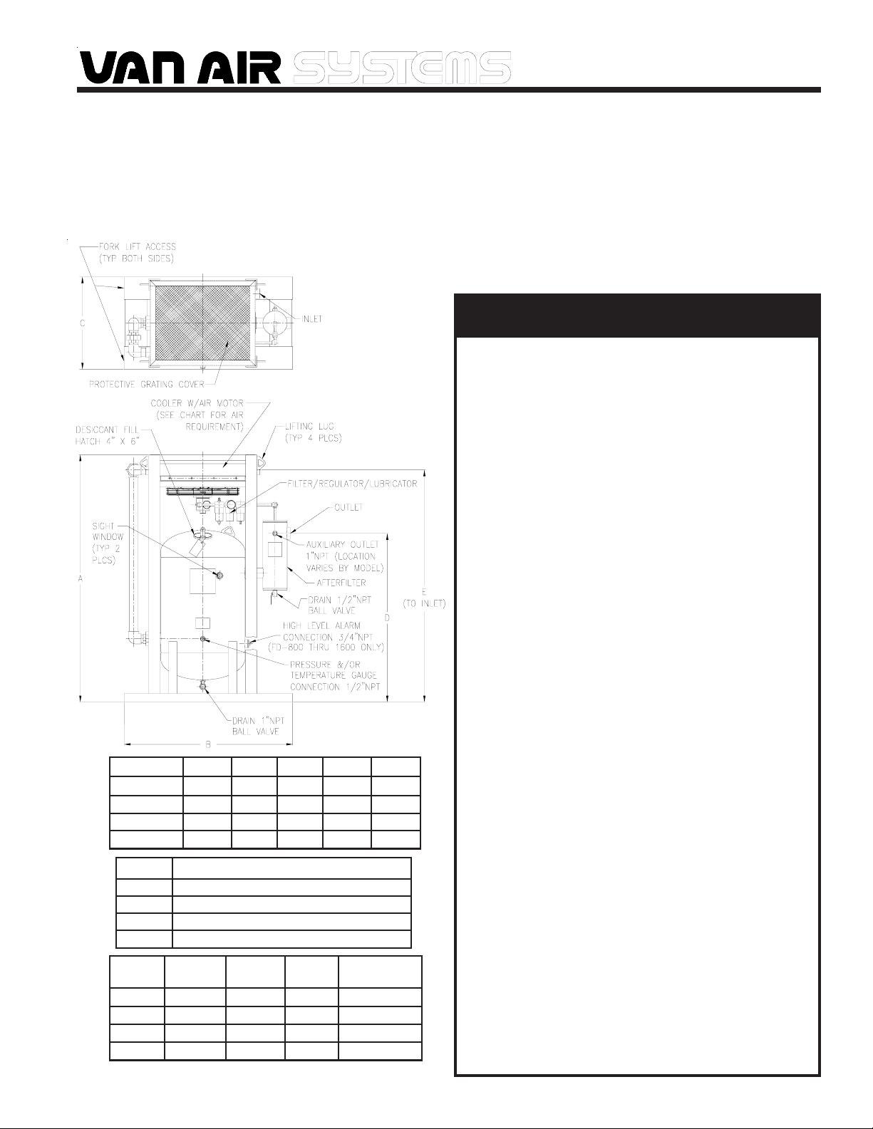
MODEL
FD-400
FD-800
FD-1200
FD-1600
MODEL
FD-400
FD-800
FD-1200
FD-1600
MODEL
FD-400
FD-800
FD-1200
FD-1600
* - ORIGINAL FILL OF DESICCANT SUPPLIED - CUSTOMER TO INSTALL
A
77"
83-3/4"
88"
94-1/2"
REGULATOR SETTING FOR AIR MOTOR
INLET
2" NPT
2-1/2"NPT
2-1/2"NPT
3" NPT
B
49"
54"
60"
71-1/2"
20 PSIG TO GET 1725 RPM
22 PSIG TO GET 1725 RPM
30 PSIG TO GET 1725 RPM
20 PSIG TO GET 1725 RPM
OUTLET
2" NPT
2-1/2"NPT
3" NPT
3" NPT
C
26"
32-7/8"
32-7/8"
43"
WEIGHT
760 lbs
1155 lbs
1525 lbs
1875 lbs
D
58-9/16"
59-1/2"
60"
59-1/8"
DRY-O-LITE
DESICCANT *
E
72-1/8"
78-3/8"
82-5/8"
89-3/8"
400 lbs
500lbs
750 lbs
1000 lbs
DO NOT ATTEMPT TO REMOVE OR REPAIR ANY PART OF THE
SYSTEM UNTIL IT IS COMPLETELY DEPRESSURIZED. SERIOUS
PERSONAL INJURY MAY RESULT IF THIS SAFETY RULE IS
NOT FOLLOWED.
DO NOT WELD, GRIND, OR SAND VESSEL, THIS WILL MAKE
IT UNSAFE TO OPERATE. (Note: Any alteration to the vessel
will void the ASME Code Certification and the warranty.)
INSPECT VESSEL, INSIDE AND OUT, REGULARLY FOR
BULGES, CORROSION, DENTS, GOUGES, LEAKS OR SIGNS
OF FIRE. IF DAMAGED, REMOVE FROM SERVICE
IMMEDIATELY AND NOTIFY YOUR CERTIFYING AUTHORITY.
DO NOT TRY TO TIGHTEN A LEAKING HATCH COVER.
IMMEDIATELY SHUT OFF THE AIR SUPPLY AND
DEPRESSURIZE THE SYSTEM.
DO NOT ATTEMPT TO REMOVE THE HATCH COVER UNTIL
THE SYSTEM IS COMPLETELY DEPRESSURIZED. WHEN
THE VESSEL PRESSURE IS REDUCED TO ZERO, THE
HATCH COVER CAN BE REMOVED BY HAND.
INSTALL A NEW GASKET EVERY TIME THE HATCH COVER
IS REMOVED, OR AT LEAST ONCE PER YEAR. INSPECT
THE COVER AND SEALING SURFACE FOR DAMAGE SUCH
AS CORROSION, CRACKS, OR DISTORTION. IF THERE IS
ANY DAMAGE, REPLACE COVER. REPLACE THE HATCH
COVER EVERY FIVE YEARS REGARDLESS OF CONDITION.
USE VAN AIR AUTHORIZED PARTS ONLY.
DO NOT USE POWER TOOLS OR CHEATER BARS TO
TIGHTEN THE NUT ON THE HATCH COVER. TOO MUCH
FORCE CAN DISTORT THE COVER AND/OR THE GASKET. IF
DAMAGED BY OVERTIGHTENING, THE COVER CAN BLOW
OUT AND CAUSE SERIOUS INJURY. (Note: Tighten the nut
until it is snug. When the vessel is pressurized, the pressure
on the cover will complete the seal.)
THE USE OF CHEMICALS OTHER THAN VAN AIR
DESICCANT WILL VOID THE WARRANTY ON THE BLAST
PAK.
PAGE 1
Page 2
SECTION 1 DESCRIPTION OF OPERATION
A Blast Pak is a skid mounted system consisting of an air-cooled trim cooler, a single tower dryer with a bed of desiccant tablets and a coarse
afterfilter. Wet warm air enters the trim cooler where it is cooled to a temperature approaching ambient. Water is condensed out during this
cooling process. The saturated air and the liquid water proceed to the inlet of the single tower dryer. The liquid water and any solid particles
present are separated by gravity and fall to the dryer sump area. The process air moves upward through the bed of desiccant tablets which
attract and absorb moisture from the air before it flows through the dryer outlet. The tablets dissolve gradually as they absorb the moisture.
The solution, which consists of dissolved desiccant and water, falls into the sump area at the bottom of the vessel. The dryer must be
drained periodically to remove the accumulated solution. A manual ball valve is supplied for this purpose. A pneumatic drain valve is
available as optional equipment for automatic draining. Likewise, the desiccant in the dryer must be periodically replenished to maintain
performance. The coarse afterfilter is supplied to catch any residuals that may work their way downstream.
SECTION 2 PERFORMANCE
2.1 INLET CONDITIONS
The Blast Paks are rated as follows: 400 SCFM (FD400), 800 SCFM (FD800), 1200 SCFM (FD1200) and 1600 SCFM (FD1600) respectively
at 100 PSIG, 180° F into the trim cooler (sized for 90° F ambient and 10° approach). Approach temperatures will vary with changes to the inlet
conditions (flow, pressure, temperature) and the ambient temperature. The dew point out of the dryer tower is directly related to the inlet
temperature entering the dryer vessel. The lower the inlet temperature, the lower the dew point of the outlet air.
The aftercooler maximum inlet temperature is 250° F. When using DRY-O-LITE desiccant, the inlet temperature to the dryer tower should not
exceed 100° F.
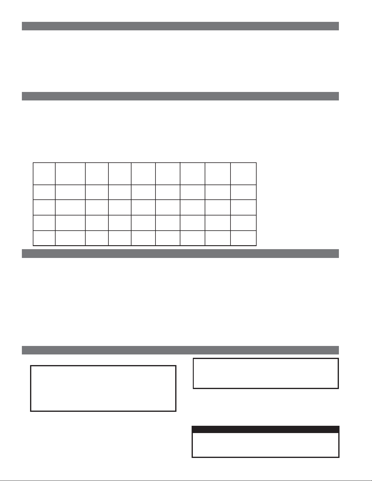
2.2 MAXIMUM CAPACITIES FOR DRYER - SCFM (Nm3/hr)
MODEL
FD-400
FD-800
FD-1200
FD-1600
MAXIMUM
WORKING
PRESSURE
200 PSIG
13.8 Bar
200 PSIG
13.8 Bar
200 PSIG
13.8 Bar
175 PSIG
12.1 Bar
60 PSIG
4.1 Bar
261
419
521
838
782
1256
1042
1675
80 PSIG
5.5 Bar
330
531
661
1062
991
1593
1321
2124
100 PSIG
6.9 Bar
400
643
800
1286
1200
1929
1600
2572
125 PSIG
8.6 Bar
487
783
974
1567
1462
2350
1949
3133
150 PSIG
10.3 Bar
574
923
1149
1847
1723
2770
2297
3694
175 PSIG
12.1 Bar
662
1064
1323
2127
1985
3191
2646
4254
200 PSIG
13.8 Bar
749
1204
1497
2408
2246
3611
-
-
SECTION 3 OPTIONS
3.1 PRESSURE RELIEF VALVE
A 2" NPT coupling is provided on the back of the dryer vessel for
installing the relief valve. A pressure relief valve should be installed to
conform to OSHA safety standards. Refer to OSHA Standard Section
1910.169, paragraph “b”, subparagraph “3” and any other federal, state
or local codes concerning pressure vessels.
See section 6 for recommended relief valves (available from your Van
Air rep.)
3.2 PNEUMATIC DRAIN VALVE (P/N 39-0284)
The 1"NPT drain connection can be fitted with a PDV-500T pneumatic
drain valve for automatic draining of the vessel. Ask your local Van Air
representative for details.
3.3 GAUGE KITS
A 1/2" NPT coupling is provided on the lower front of the dryer for
installing gauges.
See Section 6 for optional gauge kits (available from your Van Air
rep.)
3.4 HIGH LEVEL ALARM (P/N 26-3667)
A 3/4"NPT connection is provided, on the FD800 through FD1600, for installing a HLA-120 High Level Alarm to alert personnel
that the drain solution in the dryer has reached an unacceptable
level. Ask your local Van Air representative for details.
SECTION 4 OPERATION
4.1 DESICCANT INSTALLATION
IMPORTANT
The Blast Pak is shipped WITHOUT the desiccant installed.
The desiccant MUST BE INSTALLED before using the
system.
THE USE OF CHEMICALS OTHER THAN VAN AIR
DESICCANT WILL VOID THE WARRANTY ON THE DRYER.
The procedure for filling the dryer with desiccant is outlined in
Section 5.6 of this manual.
The Blast Pak is shipped WITHOUT the lubricator oil
installed. The lubricator oil MUST BE INSTALLED before
using the system.
4.3 START UP PROCEDURES
SLOWLY pressurize the air system. Allow some air to bleed
through the manual drain valve. Once the system starts to
pressurize, the manual drain valve can be closed. The Blast Pak
is now in operation.
IMPORTANT
CAUTION
4.2 LUBRICATOR OIL
Check oil level in lubricator regularly and add oil as required.
PAGE 2
Make sure that the Blast Pak is not subjected to sudden
flow surges. Always open the valves slowly to permit
gradual equalization of pressure between the Blast Pak
and the air supply lines.
Page 3
SECTION 4 OPERATION
Verify that regulator pressure is set as shown on page 1 of this
manual to maintain 1725 rpm fan speed to ensure proper
aftercooler performance.
4.4 OPERATION
The simple design of the single tower dryer allows for easy
operation. The dryer requires two procedures to ensure peak
performance.
4.4-A DAILY DRAINING
The accumulated desiccant and water solution in the bottom
of the dryer should be drained frequently. If a manual drain
valve is installed on the dryer, it must be opened at least
once every 4 to 8 hours to drain the dryer.
The dryer may require draining on a more frequent basis on
humid days. If a pneumatic drain valve is installed on the
dryer, it will drain automatically as needed.
If the dryer is not drained regularly, it may become
flooded and the accumulated liquid may enter the air
system and cause damage to downstream equipment.
4.4-B REFILLING THE DRYER WITH DESICCANT
During the drying process, the desiccant tablets dissolve slowly.
The desiccant consumption rate is dependent on several factors,
such as inlet temperature, flow and pressure. To check the level
of the desiccant bed, look into one of the sight windows. If light can
be seen through the opposite sight window, the desiccant supply
must be replenished to ensure dryer performance.
Reference Section 5 for refilling instructions and estimated
consumption rates.
The use of other than Van Air desiccant will void the
warranty on the Blast Pak.
CAUTION
IMPORTANT
SECTION 5 MAINTENANCE
5.1 DRAIN VESSEL DAILY
Drain the vessel by opening the drain valve and allowing the solution
to discharge; then close the drain valve completely. The accumulated
solution must be drained after every 4 to 8 hours of operation. An
optional pneumatic drain valve can be installed to drain the vessel
automatically as needed.
IMPORTANT
The drain solution may contain lubricants. Comply with all
applicable regulations concerning the disposal of these
chemicals.
5.2 CHECK DESICCANT LEVEL BEFORE OPERATION
Look into one of the sight windows. If light can be seen through the
opposite sight window, the desiccant supply must be replenished to
ensure dryer performance.
WARNING
IF THE SIGHT WINDOWS ARE DAMAGED IN ANY WAY,
THEY MUST BE REPLACED IMMEDIATELY WITH VAN AIR
PART NO. 26-0104 only.
Check the operation of all equipment installed before and after the
Blast Pak.
Inspect the hatch cover for signs of corrosion and/or leaks. Replace
the cover and/or gasket as necessary.
5.3 CHECK OIL LEVEL IN LUBRICATOR
Verify that there is sufficient amount of oil in the lubricator and add
oil as needed. See section 6 for oil part number.
5.4 CHECK FILTER IN FRL
Replace filter as needed. See section 6 for fliter part number.
5.5 CLEAN AFTERCOOLER CORE
The core should be cleaned regularly. Accumulation of dirt or other
contaminants such as oils will greatly reduce the efficiency of the
aftercooler.
Push on the hatch cover. If the vessel is depressurized, the cover will
unseal. Once the seal is broken, tilt the hatch cover and remove it
from the dryer.
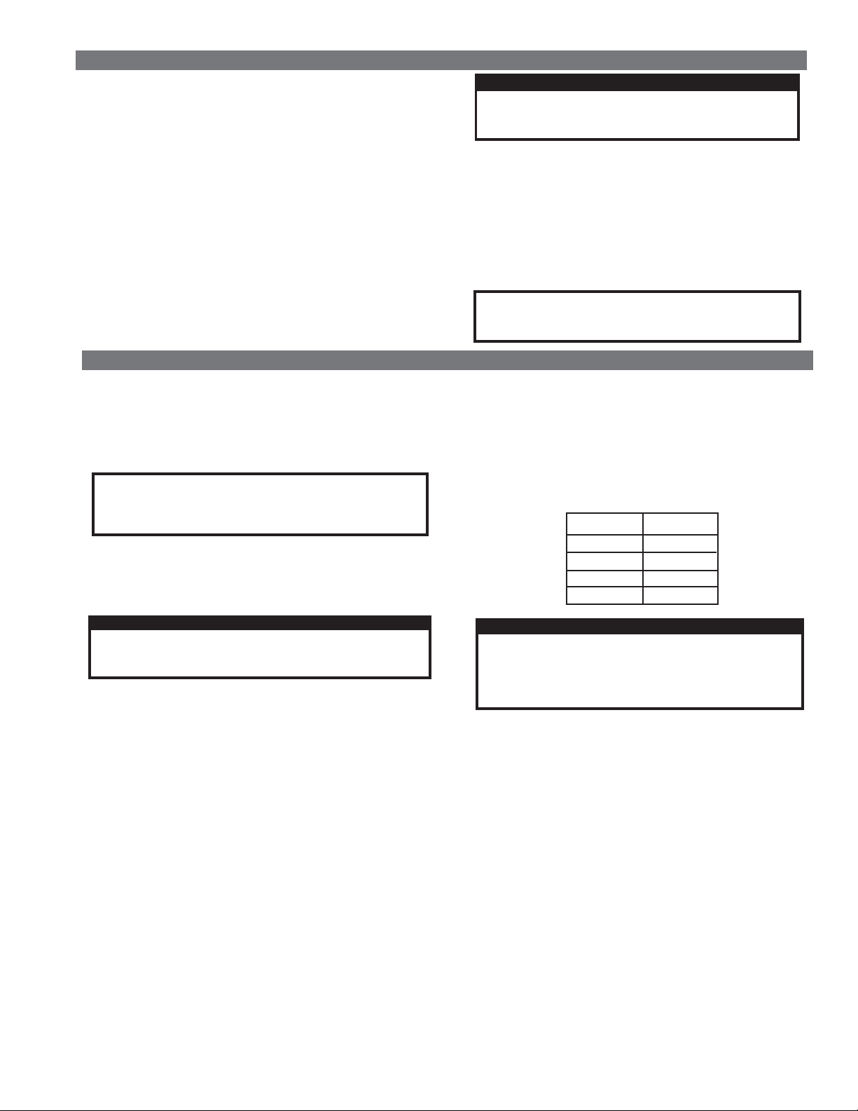
Add the amount of desiccant tablets required to raise the supply to
the maximum operating level; then level off the tablet bed.
Amount of desiccant required to fill from sight window to
maximum fill level:
MODEL
FD-400
FD-800
FD-1200
FD-1600
DRY-O-LITE
150lb.
250 lb.
250 lb.
400 lb.
CAUTION
Make sure the desiccant level is below the screen on the
outlet pipe.
Do NOT overfill the vessel. Adequate space must be left
to allow the hatch cover to be installed.
Inspect the hatch cover and sealing surface. If there is any damage,
replace the cover. Replace the cover every 5 years regardless of
condition. The gasket should be replaced every time the hatch cover
is removed or at least once a year.
Check the sealing surface of the opening. If it is contaminated with
dirt or rust, it must be cleaned before installing the hatch cover. A
contaminated surface may prevent the gasket from properly sealing.
Install the filler hatch cover and a new gasket. Tighten the nut on the
hatch cover until it is snug. Overtightening will cause damage to the
nut. The cover will seal when the vessel is pressurized.
Start up the dryer following the procedures in Section 4.3.
Normal accumulation of dirt can be removed by blowing the core off
with compressed air. If the core becomes contaminated with oilladen particles, it can be steam cleaned. Clean with extreme care
as the aluminum fins can be easily damaged.
5.6 ADDING DESICCANT
Shut down the air system and open the drain valve to allow the dryer
to depressurize completely.
Loosen the nut on the hatch cover.
5.7 ESTIMATING DESICCANT USAGE
The ANNUAL DESICCANT CONSUMPTION RATE table is a guide
to estimate the desiccant usage for your installation.
The consumption rate is an approximation of how much
desiccant will be added over a period of one year.
The figure is an average and may vary depending upon your actual
conditions (i.e. 24 hour operation, higher inlet temperature, excessive
liquid water content, contaminants etc.)
PAGE 3
Page 4
SECTION 5 MAINTENANCE
The desiccant bed level should be maintained to at least the sight
window level at all times to ensure optimum drying capabilities.
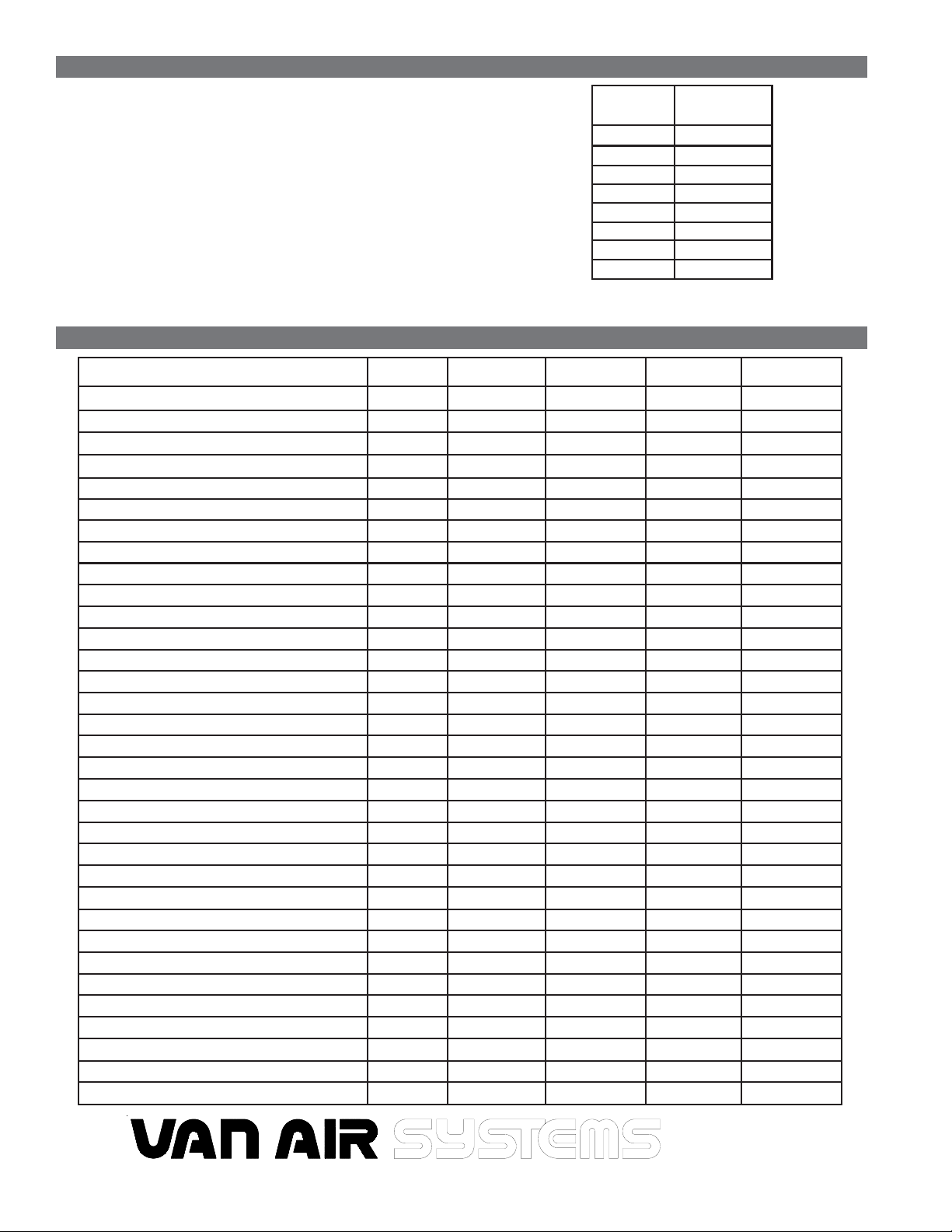
To use the chart, first determine the SCFM that is being processed
through the Blast Pak. Then locate the nearest flow rate listed on the
chart and interpolate as needed.
(This chart is based on 1 shift for a one year period (2,000 hours)@
100 psig inlet pressure and 75
100% RH.)
The consumption rate is proportional to the moisture loading. Each
20oF increase in inlet temperature changes the moisture loading by a
factor of nearly 2:1.
For special applications requiring desiccants other than DRY-O-LITE,
consult factory.
o
F inlet temperature into dryer vessel,
FLOW
SCFM
200
400
600
800
1000
1200
1400
1600
DRY-O-LITE
LBS/YEAR
264
528
792
1056
1320
1584
1848
2112
SECTION 6 REPLACEMENT PARTS
DESCRIPTION
Gasket for 4"x6" hatch cover
Hatch Cover, 4" x 6"
Sight Window
Manual Drain Valve 1" NPT
Manual Drain Valve 1/2" NPT
Air Motor for Aftercooler
Air Motor for Aftercooler
Air Motor for Aftercooler
Filter-Regulator-Lubricator
Filter-Regulator-Lubricator
Filter-Regulator-Lubricator
Element for FRL
Element for FRL
Element for FRL
Oil for Lubricator (Quart)
PART NO.
18-0394
46-3003
26-0104
14-0451
14-0450
26-6277
34-0926
34-0925
26-7039
26-7009
26-6836
26-7056
26-7027
26-7030
26-7032
FD-400 QTY
1
1
2
1
1
1
-
-
1
-
-
1
-
-
1
FD-800 QTY
1
1
2
1
1
-
1
-
-
1
-
-
1
-
1
FD-1200 QTY
1
1
2
1
1
-
1
-
-
1
-
-
1
-
1
FD-1600 QTY
1
1
2
1
1
-
-
1
-
-
1
-
1
1
DESICCANT
DRY-O-LITE Desiccant, 50 LB BAG
DRY-O-LITE Desiccant, 506 LB DRUM
OPTIONAL EQUIPMENT
Relief Valve 3/4" NPT 200# set pressure
Relief Valve 1-1/2" NPT 200# set pressure
Relief Valve 1-1/2" NPT 175# set pressure
Pressure gauge kit
Pressure gauge only
Temperature gauge kit
Temperature gauge only
Thermowell only
Combination pressure/temperature gauge
HLA-120 High level alarm kit
Automatic drain valve PDV-500T
White touch up paint (9 oz. spray can)
PAGE 4
33-0311
33-0203
14-1800
14-2307
14-2308
29-0252
29-0151
29-0326
29-0108
29-0107
29-0200
26-3667
39-0284
45-0152
8
-
1
-
1
1
1
1
1
1
1
1
www.vanairsystems.com
10
15
1
-
1
1
1
1
1
1
1
1
1
1
2
-
1
1
1
1
1
1
1
1
1
1
2950 Mechanic Street
Lake City, PA 16423-2095
Phone: 814-774-2631
20
2
-
1
1
1
1
1
1
1
1
1
1
 Loading...