

Page 1
INSTALLATION, OPERATION & MAINTENANCE INSTRUCTIONS
ENTER
MODE
SENTINEL
MOTORIZED BALL VALVE WITH ADJUSTABLE CYCLE TIME
Model MDV400L
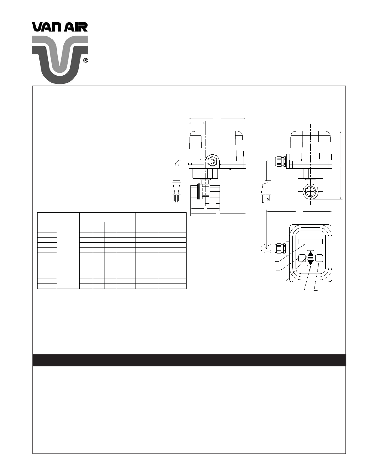
FIGURE 1
NOTES:
1. RATED PRESSURE: BRASS 600 PSIG COLD WOG.
2. VALVES ARE FULL PORT 2 PIECE BALL VALVES
3. AVAILABLE ELECTRICAL: -115VAC-1PH-50/60HZ, MAX CURRENT: 1.7 AMPS
(DC VOLTAGE UNITS ARE SUPPLIED WITH POWER CORD BUT WITHOUT PLUG)
4. TIME SETTINGS:
OPEN TIME: 1 SECOND TO 99 MINUT ES & 59 SECONDS AT 1 SECOND INCREMENTS.
CLOSED TIME: 1 MINUTE TO 99 HOU RS & 59 MINUTES AT 1 MINUTE INCREMENTS.
5. ENCLOSURE RATING: NEMA 1
6. AMBIENT TEMPERATURE OPERATI NG RA NGE: 40 TO 120°F
7. VALVE INTERNAL MATERIALS:
BRASS VALVES; BALL-CHROME PLATED BRASS
316 SS VALVES; BALL-316SS
SS 900 PSIG COLD WOG
-230VAC-1PH-50/60HZ, MAX CURRENT: 0.9 AMPS
-12VDC, MAX CURRENT: 1.7 AMPS
-24VDC, MAX CURRENT: 0.9 AMPS
STEM-BRASS, NICKEL PLATED
SEAT-RTFE
STEM-316SS
SEATS-PTFE/TFM
1.72
†
October 2011
P/N 432-10035-B
®
6.00
C
† NOTE: Display may be sluggish at temperatures below 40°F and darkened at
temperatures approaching 110°F (f or best results, keep out of direct sunlight).
VALVE
SIZE
(NPT)
1/2"
3/4"
1 1/2"
2-1/2"
1/2"
3/4"
1 1/2"
VALVE
MATERIAL
1"
BRASS
2"
3"
STAINLESS
STEEL
1"
(316 SS)
2"
* ACTUATOR TORQUE FOR THESE UNITS WITH DC VOLTAGE IS 300 IN/LBS.
DIMENSIONS
B
A
2.60
5.58
2.93
5.75
6.06
4.60
6.58
5.31
6.94
6.10
7.33
6.89
7.73
2.80
5.68
3.00
5.78
3.43
6.00
4.46
6.51
5.40
6.98
C
7.02
7.51
7.83
9.13
9.72
10.86
11.65
7.78
7.93
8.43
9.48
10.23
ACTUATOR
WEIGHT
10.65
12.96
11.65 150*
14.88
(LBS)
8.16
8.39
8.833.56
16.14
21.16
8.18
8.67
9.66
TORQUE
(IN/LBS)
COEFFICIENT
150*
150*
150*
150*
300
600
600
150*
150*
150*
300
FLOW
CV
19
34
52
143
205
475
780
38
71
110
350
600
B/2
B
A
LCD DISPLAY
MODE BUTTON
ADJUST UP
BUTTON
ADJUST DOWN
BUTTON
6.81
MODE
ENTER
ENTER BUTTON
Thank you for buying this product.
For optimum performance and safety, please read and understand all instructions before installation.
Personnel must use safe working practices and observe all applicable local and international regulations, safety, health and legal requirements when
installing and operating this product. Improper operation or maintenance of this product could be potentially dangerous resulting in an accident
causing injury or death. Van Air Systems cannot anticipate every possible circumstance, which represents a potential hazard. The Warnings in this
manual cover the most common potential hazards and are therefore not all-inclusive. The installation and maintenance of this product must be in
strict accordance with this instruction manual or the warranty will be invalidated.
WARNINGS
DO NOT REMOVE OR REPLACE ANY PART OF THE PRODUCT WHILE IT IS UNDER PRESSURE. SERIOUS PER-
•
SONAL INJURY AND/OR DAMAGE TO THE PRODUCT MAY RESULT.
DO NOT OPERA TE THE PRODUCT IF THERE ARE ANY PRESSURE LEAKS. IF A LEAK IS PRESENT, THE PRODUCT
•
MAY BE UNSAFE TO OPERATE. REMOVE THE PRODUCT FROM SERVICE IMMEDIATELY.
DO NOT OPERATE THIS PRODUCT ABOVE ITS MAXIMUM OPERATING PRESSURE AND/OR TEMPERATURE.
•
WHEN INSTALLING THIS PRODUCT, BE SURE TO COMPLY WITH ALL LOCAL, STATE, INTERNATIONAL, AND/OR
•
GOVERNMENT LAWS, RULES, REGULATIONS AND CODES APPLICABLE TO YOUR INSTALLATION.
DO NOT INSTALL THIS PRODUCT IN A MANNER THAT DISCHARGES TOWARDS PEOPLE OR EQUIPMENT. SERI-
•
OUS INJURY AND/OR DAMAGE MAY RESULT.
PROPER DISPOSAL OF DRAINED LIQUIDS THROUGH THIS PRODUCT ARE THE RESPONSIBILITY OF THE USER.
•
PAGE 1
Page 2
1.0 DESCRIPTION OF NORMAL OPERATION:
1.1 This product consists of a quarter turn ball valve mated to an electric actuator with a fully adjustable timer
controller. The product is designed for mounting in a pipe-line requiring adjustable set closed times and
adjustable set open times. A common application is draining fl uids from compressed air system components
such as separators, fi lters, airlines and receiver tanks. The timer is set at the factory to open the valve for 10
seconds every 2 hrs.
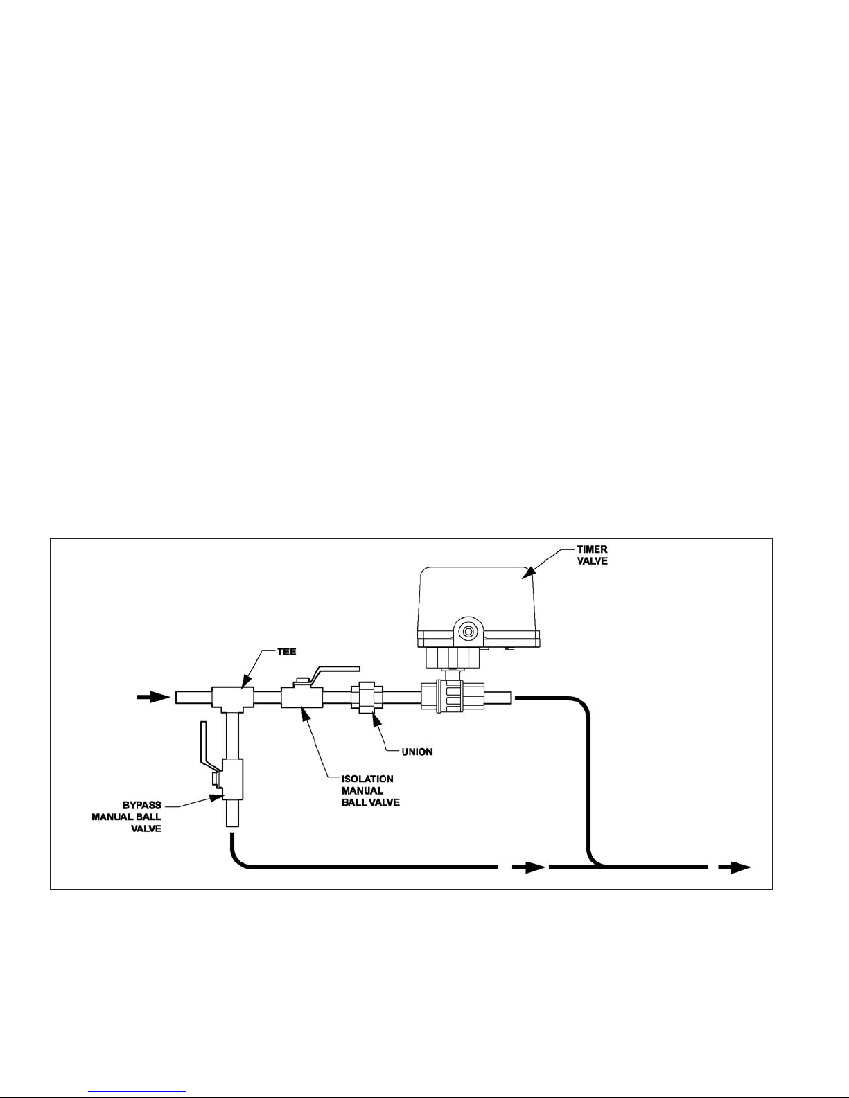
2.0 INSTALLATION INSTRUCTIONS: (Reference Figure 2)
2.1 Carefully unpack the valve from its shipping box or boxes. Check for visible signs of damage immediately fi le a
claim with the carrier if damage is found. Do not install a damaged valve or actuator. Note: 2” valves and larger
will be shipped in two boxes, one containing the valve and one containing the actuator. Smaller valves are
shipped with actuator installed.
2.2 2” valves and larger will require installing the actuator after installing the valve in the line (See Figure 3).
2.3 Make sure that all pressure is removed from the line where the valve is to be installed. Make precautions to
ensure the line remains free of pressure during the installation process.
2.4 Check the line for obstructions and clean as required.
2.5 Make sure all components and parts you are installing meet the temperature and pressure ratings of your
system. (piping, manual valves, fi ttings, or electrical parts are not included)
2.6 Install a tee onto the line with the outlet facing down. Install a nipple and manual ball valve on the tee facing
down. This is for bypassing the timer valve if it is not operational for any reason.
2.7 Install an isolation valve on the remaining opening. Close both manual valves and install a nipple and union on
the isolation valve.
2.8 Install the valve after the union and install all additional piping downstream of the valve and bypass valve per
your local requirements.
2.9 Locate a suitable power source and verify it meets the requirements of your valve (see valve label). Wire the
valve using the cord included or conduit taking all precautions necessary to meet all required electrical codes for
your location. Verify your timer valve is in the closed position and that timing is per your needs.
2.10 Review steps 2.1 through 2.9 to verify no steps were skipped.
2.11 Slowly pressurize the system. Once the system is fully pressurized, slowly open the isolation valve and check
the system for leaks. In the event a leak is discovered, remove pressure from the system and repair before
proceeding.
2.12 Your valve is now installed and ready for operation.
FIGURE 2 RECOMMENDED INSTALLATION
CAUTION: DO NOT INSTALL MORE THAN ONE FLOW SOURCE PER VALVE. MULTIPLE SOURCES WILL HAVE VARIED
PRESSURES RESULTING IN HIGHEST TO LOWEST CONTAMINATION.
PAGE 2
Page 3
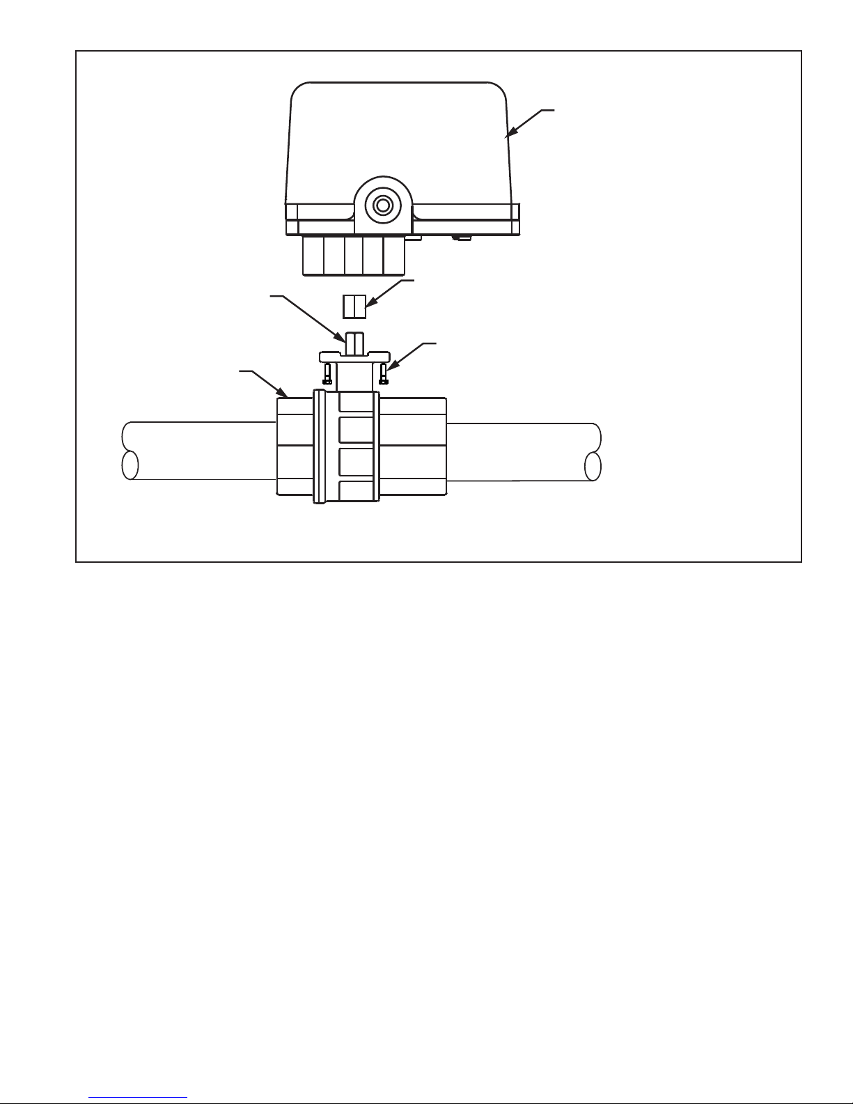
FIGURE 3 ASSEMBLY OF ACTUATOR AND VALVE (1-1/2” AND LARGER)
ACTUATOR
STEM ADAPTER
VALVE STEM
BALL VALVE
(1) NEEDED FOR 1-1/2” AND 2” VALVE.
NO STEM ADAPTERS ARE NEEDED FOR 2-1/2” AND 3” VALVES.
MOUNTING BOLTS (4 EACH)*
MOUNTS BALL VALVE TO ACTUATOR
3.0 ADJUSTING THE TIMER
3.1 Refer to FIGURE 1 for button description
3.2 Firmly push the mode key and up arrow key simultaneously and hold for a full 3 seconds. The display will
change to allow adjustment to the valve closed and open times.
3.3 Use the up or down arrow keys to set the hours you wish the valve to remain closed. Press the enter key. Use
the up and down arrow keys to select the minutes you wish the valve to remain closed. Press the enter key. Use
the up or down arrow key to set the minutes you wish the valve to remain open. Press the enter key. Us the up or
down arrow key to set the seconds you wish the valve to remain open. Press the enter key. Your timer is now set.
4.0 REQUIRED MAINTENANCE
Periodically check the valve for the following:
4.1 Press and hold the Mode and Enter key for 3 seconds to verify valve rotation. The display should say “OVER-
RIDE” and the valve should rotate from closed to open and back to closed.
4.2 Check actuator to valve connection area for debris which could impede proper operation.
4.3 Check wires and/or electrical connections for signs of damage.
4.4 Check valve for leaks. If leaks are present, remove pressure from the system and replace the ball valve.
4.5 Check fasteners for tightness.
* FOR 1-1/2” & 2” VALVE USE (4) M6 X 16MM HEX HEAD SCREWS
TIGHTEN DOWN WITH A 6MM OPEN END WRENCH.
FOR 2-1/2” & 3” VALVE USE (4) M8 X 20 MM HEX HEAD SCREWS
TIGHTEN DOWN WITH A 8MM OPEN END WRENCH.
PAGE 3
Page 4
Note: Service work to be done by qualifi ed personnel only! Always remove pressure and power from the unit before servicing.
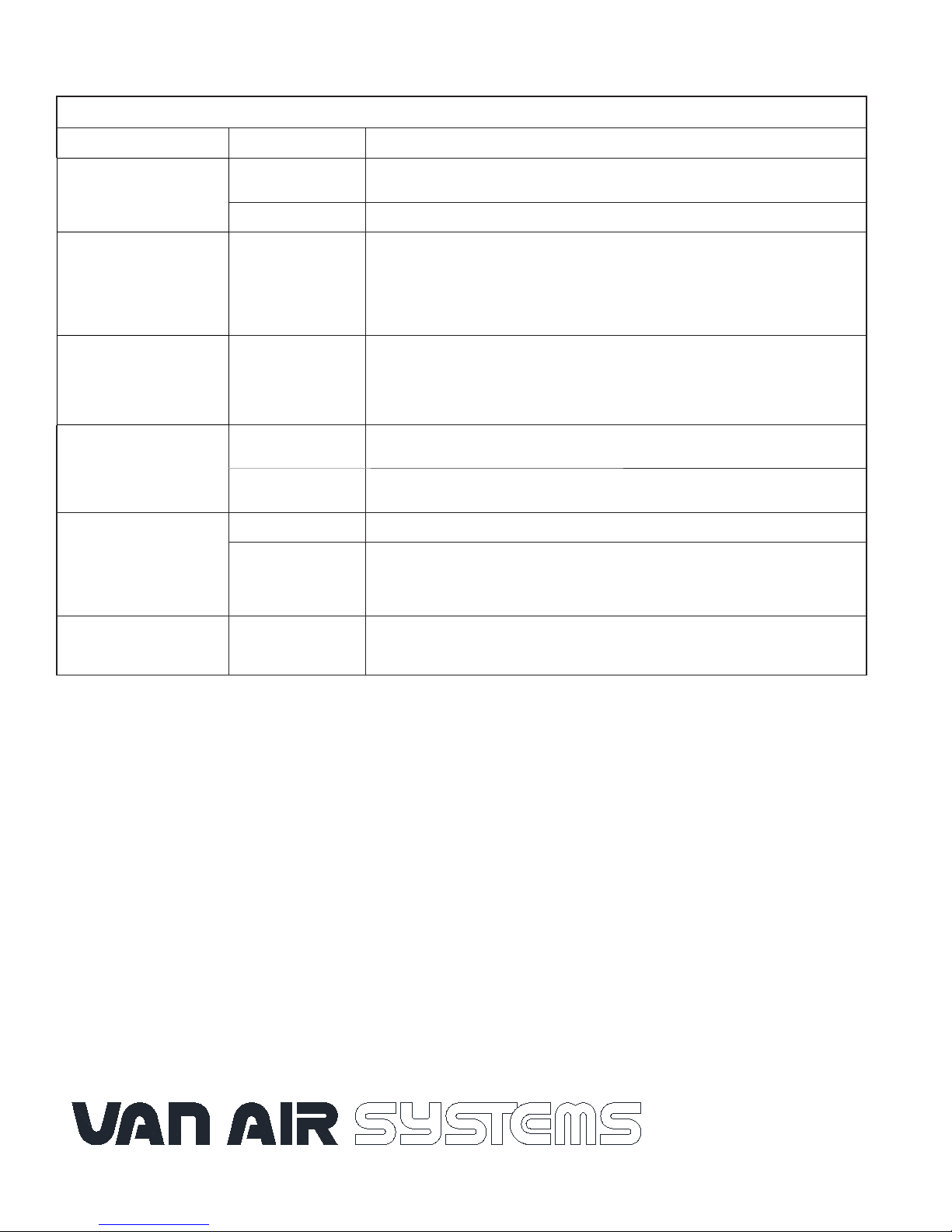
TROUBLE SHOOTING
PROBLEM CAUSES SOLUTION
Unit will not operate (No
display on LCD)
Unit will not operate (“VALVE
FAULT” displayed on LCD)
Unit will not operate (LCD
display working properly)
Valve binds during rotation
Ball valve leaks prematurely
No power
Fuse F1 is blown Replace Fuse F1.
The control board did
not sense that the
next position, closed
or open, was reached
for a period of 15
seconds
Faulty actuator/motor/
valve assembly
Ball valve seats worn Replace the ball valve.
Ball valve ball clogged
or damaged
Defective ball valve Replace ball valve.
Valve set on short
cycle time
Check power supply. Check circuit breakers or fuses. Check to see if circuit has a
remote power on/off switch.
Turn power off and back on. Press and hold Mode and Enter buttons simultaneously
for 3 seconds. If “OVERRIDE” is displayed but valve does not rotate, fuse labeled F2
on bottom board is blown. Replace fuse. If “OVERRIDE” is displayed, valve rotates
continuously and valve fault reappears, then optic sensor has failed. Contact factory.
If “OVERRIDE” is displayed, valve rotates and the timer closed time appears, then the
“VALVE FAULT” has been cleared.
Press and hold the Enter and Mode keys simultaneously for 3 seconds. If the actuator
motor turns but the valve does not, check for a broken or loose valve stem. If the stem is
broken, replace the valve. If this is not the problem, replace the entire unit. If the motor
will not turn after power is applied directly to it, the motor has failed and the unit must be
replaced.
Free valve of any debris. If valve is damaged, replace.
Ball valve should be replaced at some time between 100,000 and 150,000 cycles (will
vary with application). If cycle times are set below 5 minutes, then the ball valve will
most likely require replacing within the warranty period (based on 24-hour per day
operation). This is considered normal wear and not covered under warranty.
Display reads “OPEN” or
“CLOSED” and valve is in
the opposite position
Power Interruption
Press and hold the Enter and Mode keys simultaneously for 3 seconds. Valve will
rotate to the closed position.
V AN AIR P ARTS AND SERVICE
PHONE: 888-606-9303
FAX: 814-774-0778
E-MAIL: [email protected]
PAGE 4
2950 Mechanic Street
Lake City, Pa 16423 USA
Phone: 800-840-9906
Fax: 814-774-0778
www.vanairsystems.com
 Loading...