

Page 1

VEA 3CGi
Ethernet adapter
User’s Manual
Page 2

VEA 3CGi Ethernet adapter
User’s manual
VAMP Ltd
Table of Content
1. General...................................................................................3
1.1. Front panel ...........................................................................3
1.2. Application ..........................................................................4
1.3. Operation .............................................................................5
2. Connection.............................................................................6
2.1. Ethernet adapter ................................................................6
2.1.1. Connection to 100-series relays...............................7
2.1.2. Connection to 200-series relays...............................7
2.1.3. Connection to other VAMP products ....................8
3. Configuration..........................................................................9
3.1. The Ethernet settings of the relay .....................................9
3.2. VEA 3CGi to the relay and Ethernet network.............. 10
3.3. VAMPSET communication over the Ethernet Network11
4. Dimensional drawing...........................................................13
5. Firmware update of VEA 3CGi............................................14
6. Reference information.........................................................15
2
Vamp 24h support phone : +358 (0)20 753 3264
VMVEAi.EN001
Page 3
VAMP Ltd Ethernet adapter
User’s manual
VEA 3CGi
1. General
Installed to 35mm DIN- RAIL
Steel plate case
Powered from the VAMP relay via serial cable (from the
LOCAL port of the relay) or from an external power supply
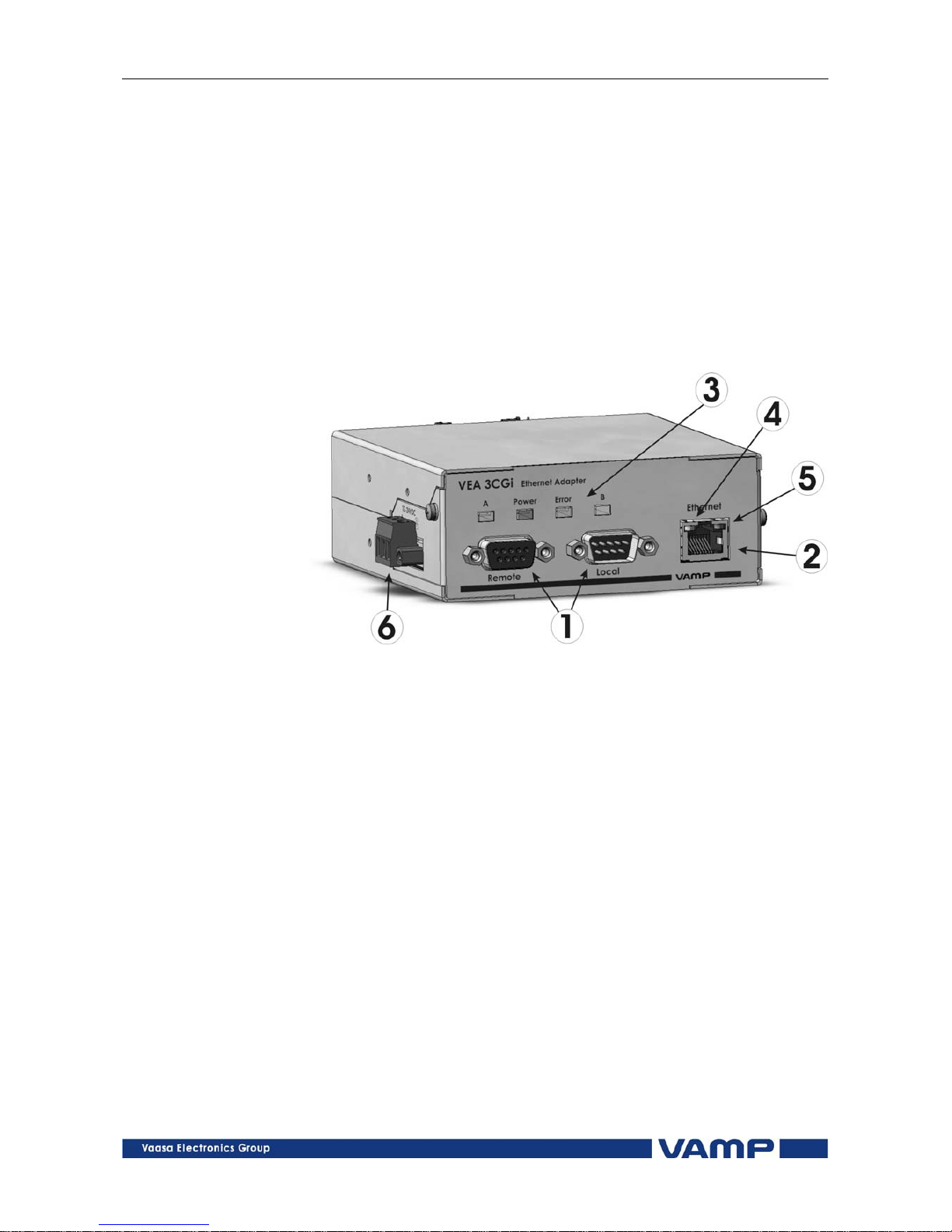
interface. There is a screw terminal (6 , see figure 1) for
connecting an external power supply.
1.1. Front panel
Figure 1.1-1VEA 3CGi front panel
1. 2 serial ports : connection to VAMP relay (Local + Remote)
2. Ethernet port : 10 Mb/s, RJ-45 connector
3. 4 LED indicators:
Power: Powered by VAMP relay
Error: Internal error
A/B Future feature
4. Act: Communication active
5. Link: Ethernet link is active
6. External power supply and grounding interface:
Range: +12..24Vdc
Power:1W
Connection: Removable terminal block
Grounding help limit the effects of noise due to
electromagnetic interference (EMI) Run the ground
connection from the right most connector of the 3contact terminal block to the grounding surface prior to
connecting devices.
VMVEAi.EN001
Vamp 24h support phone : +358 (0)20 753 3264
3
Page 4
VEA 3CGi Ethernet adapter
User’s manual
VAMP Ltd
1.2. Application
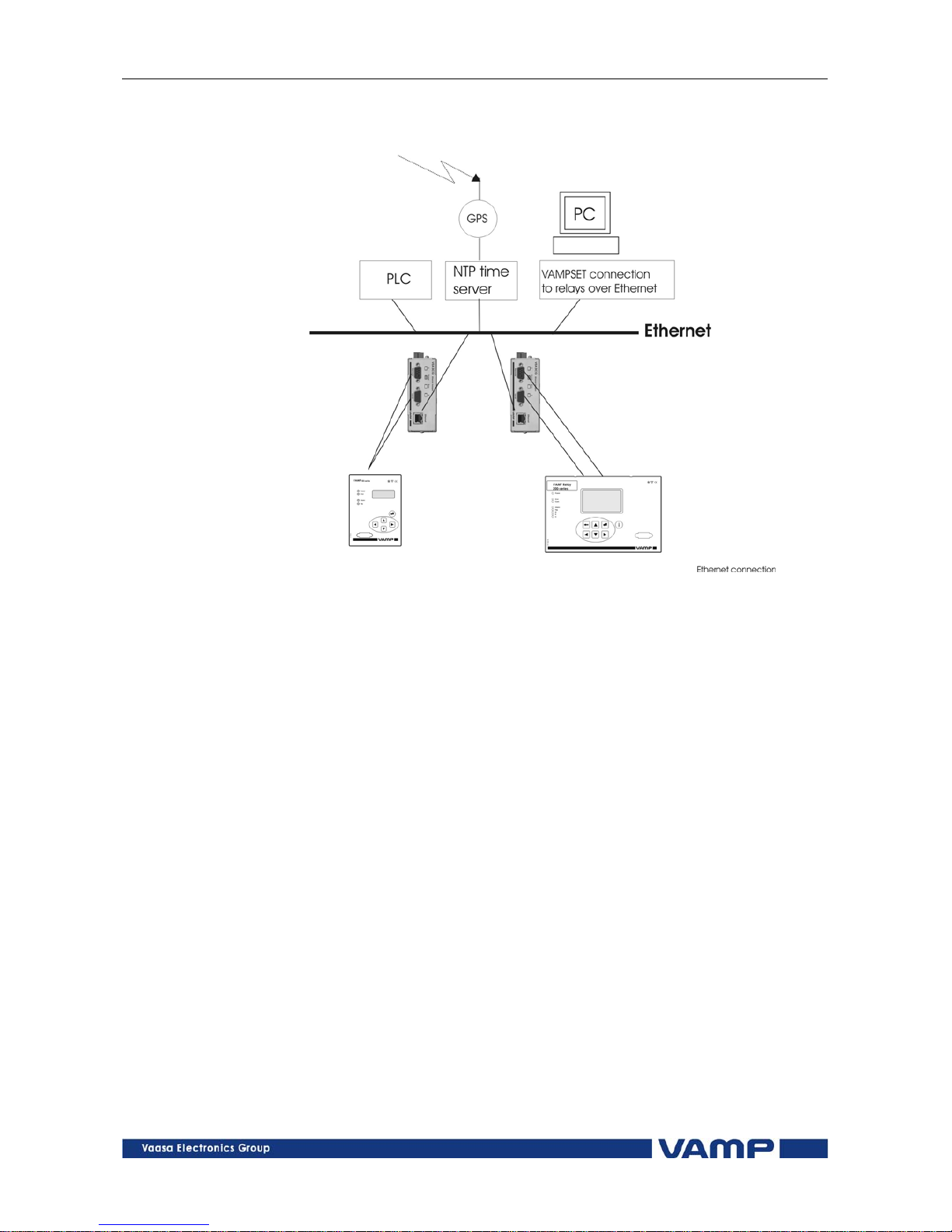
Figure 1.2-1 Application
VAMPSET data over Ethernet
Read / write of relay settings
Upload of disturbance recordings
Time synchronization of relays with NTP-server
NTP time server con
nects to Ethernet
NTP server gets its time from GPS or Internet
VEA 3CGi gets synchronized via the server, using SNTP
The relay is synchronized to VEA 3CGi via the Local
interface
Modbus TCP over Ethernet
Read / wr
ite of relay data in Modbus registers
The applicable Modbus register numbers for each VAMP
relay type can be found from documents called “ Modbus
parameters”.
The same data which is available via serial Modbus RTU
protocol is also available via Modbus TCP.
4
Vamp 24h support phone : +358 (0)20 753 3264
VMVEAi.EN001
Page 5
VAMP Ltd Ethernet adapter
User’s manual
VEA 3CGi
1.3. Operation
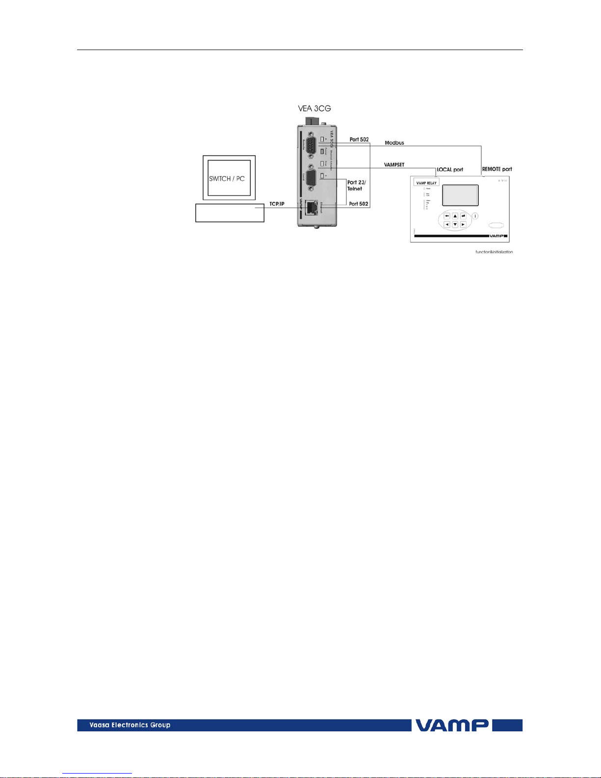
Figure 1.3-1 VEA 3CGi operation principle
Function
Open the communication tunnel between Port 23 / Telnet
and Local port, which enables the VAMPSET connection to
VAMP relay.
Open the communication tunnel between Port 502 and
Remote port, which enables the use of Remote port
protocols, e.g. Modbus TCP.
Initialization
After resetting, the VEA 3CGi performs the following the
initialization sequence:
1 Opening the Local port and configuration to speed 38400
b/s.
2 Obtaining the necessary setting from the relay through the
Local port.
3 IP setting in accordance with the information obtained from
the relay.
4 Opening and configurating of the Remote port according to
the information obtained from the relay.
5 Initialization of communication through Port 23 and 502.
6 Initialization of NTP query if IP address of the NTP server
has been obtained from the relay.
VMVEAi.EN001
Vamp 24h support phone : +358 (0)20 753 3264
5
Page 6
VEA 3CGi Ethernet adapter
User’s manual
VAMP Ltd
2. Connection
2.1. Ethernet adapter
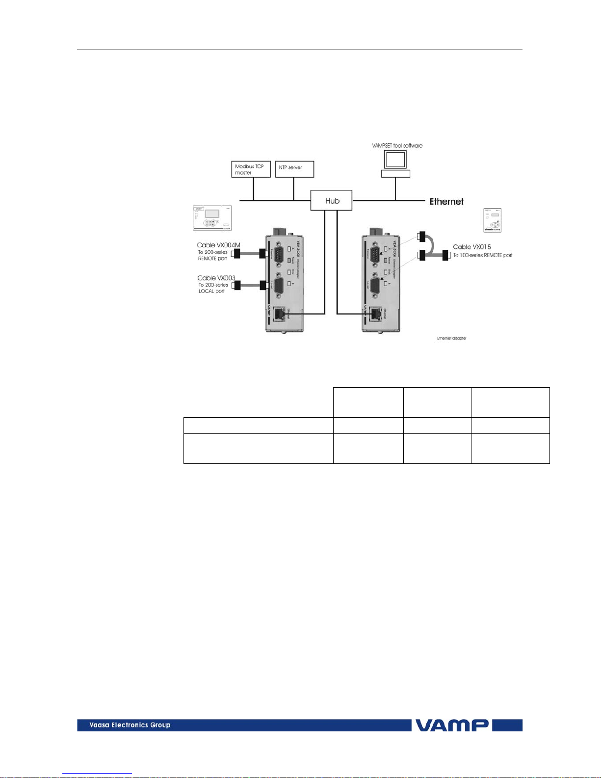
Figure 2.1-1VEA 3CGi connection cables
100-series 200-series Other VAMP
products
VAMPSET communication VX015 VX003 VX030
Modbus TCP and
VAMPSET communication
─
VX004M
and VX003
─
6
Vamp 24h support phone : +358 (0)20 753 3264
VMVEAi.EN001
Page 7
VAMP Ltd Ethernet adapter
User’s manual
VEA 3CGi
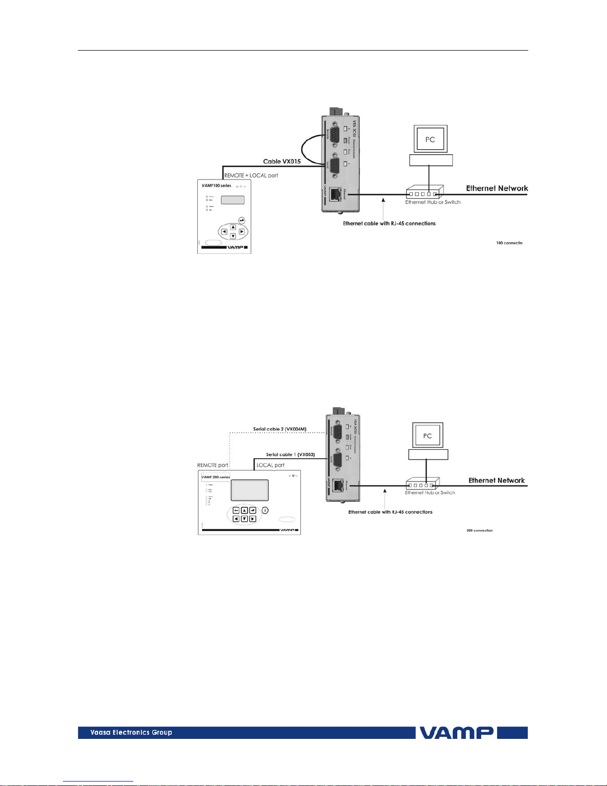
2.1.1. Connection to 100-series relays
Figure 2.1.1-1 Connection to 100-series relay
Galvanically isolated.
Modbus and VAMPSET communication over TCP/IP.
Powered by VAMP relay via VX015 cable.
The REMOTE port of the 100-series has both REMOTE
and LOCAL port signals.
Cable VX015 is connected to both ports of VEA 3CGi.
2.1.2. Connection to 200-series relays
Figure 2.1.2-1 Connection to 200-series relay
Galvanically isolated
Modbus and VAMPSET communication over TCP/IP.
Powered by VAMP relay via VX003 cable.
Serial cable 1 : RS-232 interface to LOCAL port
- VAMPSET communication
- Clock syncronization
Serial cable 2 : RS-232 interface to REMOTE port
- Modbus TCP communication
VMVEAi.EN001
Vamp 24h support phone : +358 (0)20 753 3264
7
Page 8
VEA 3CGi Ethernet adapter
User’s manual
VAMP Ltd
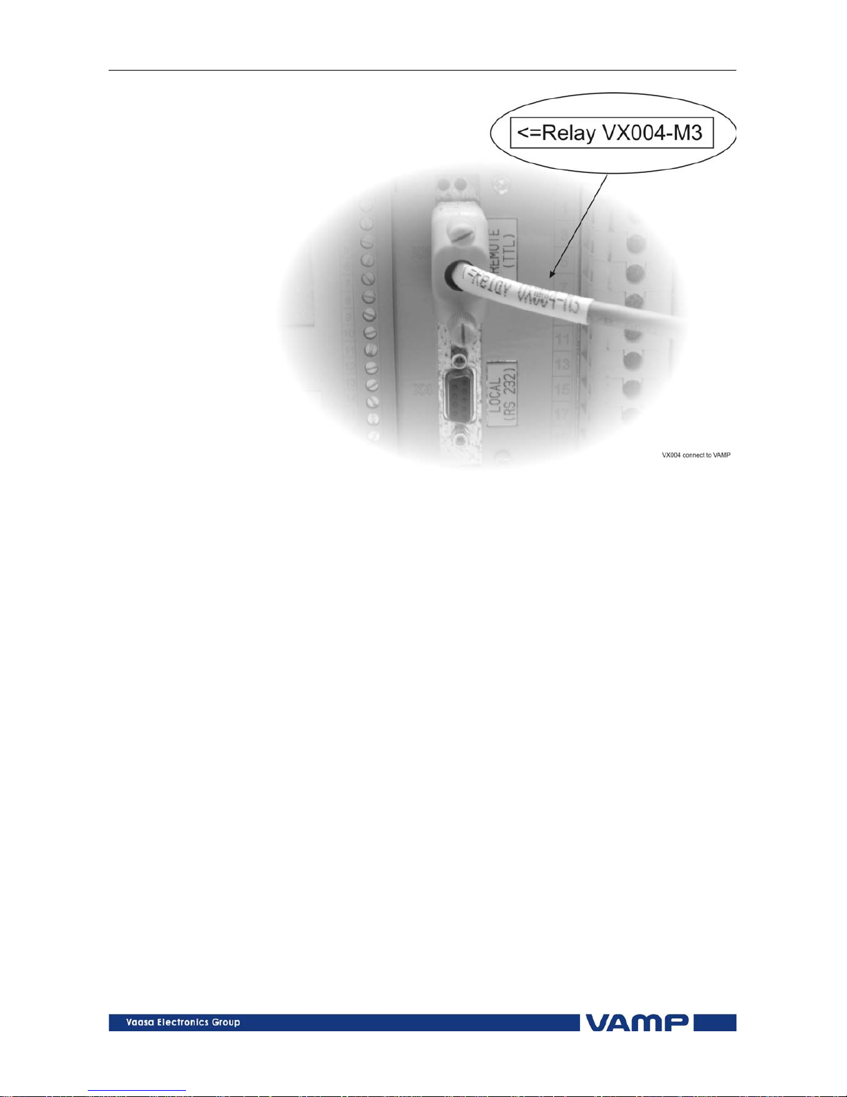
Figure 2.1.2-2 VX004 connection to 200-series relay
2.1.3. Connection to other VAMP products
VAMP40: use cable VX030
VAMP96: use cable VX030
WIMO6CP10: use cable VX030
8
Vamp 24h support phone : +358 (0)20 753 3264
VMVEAi.EN001
Page 9
VAMP Ltd Ethernet adapter
User’s manual
VEA 3CGi
3. Configuration
3.1. The Ethernet settings of the relay
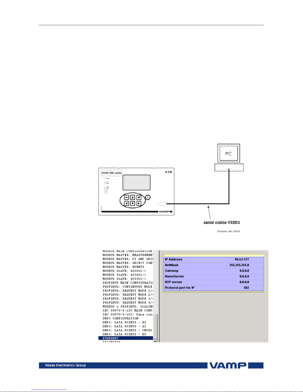
Connect cable VX003 to relay’s front panel (see Figure 3.1-1).
Find the Ethernet-menu of the relay with VAMPSET and give
proper values to parameters " IP Address " and " NetMask".
The other parameters can be left to their default values when
testing the communication.
To learn about possible IP addresses you may have to talk with
the system administrator responsible of the Ethernet network
you are going to use for communications. A fixed IP address
must be used because DHCP is not supported in VEA 3CGi.
Figure 3.1-1 Connecting cable VX003 to the relay’s front port for the
Ethernet settings of the relay.
Figure 3.1-2 Ethernet settings of the relay
VMVEAi.EN001
Vamp 24h support phone : +358 (0)20 753 3264
9
Page 10
VEA 3CGi Ethernet adapter
User’s manual
VAMP Ltd
3.2. VEA 3CGi to the relay and Ethernet
network
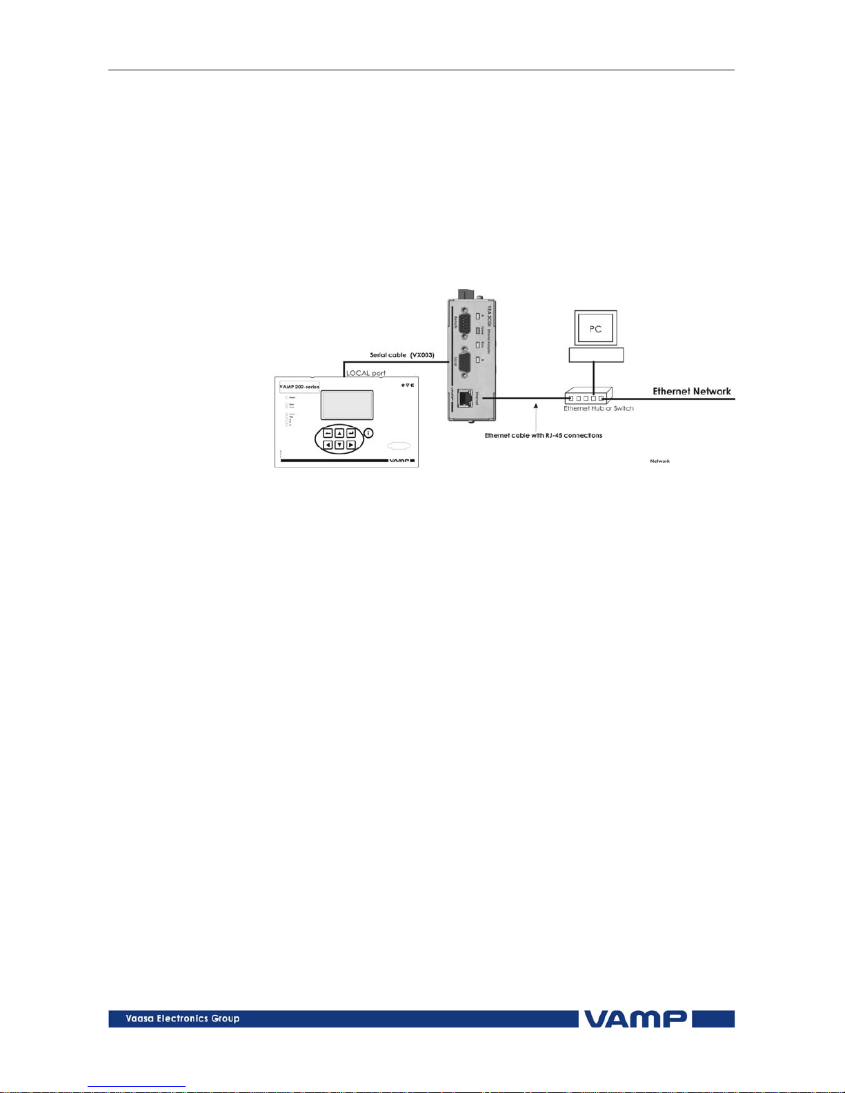
Connect VEA 3CGi to a 200-series relay’s LOCAL serial port
with cable VX003 . Connect the VEA 3CGi and the PC to an
Ethernet Switch (see Figure 3.2-1 ). Connection to 100-series
relays is done with VX015 cable and connection to VAMP 40 is
done with VX030 cable.
Figure 3.2-1 Connecting VEA 3CGi to the VAMP relay and PC
10
Vamp 24h support phone : +358 (0)20 753 3264
VMVEAi.EN001
Page 11
VAMP Ltd Ethernet adapter
User’s manual
VEA 3CGi
3.3. VAMPSET communication over the
Ethernet Network
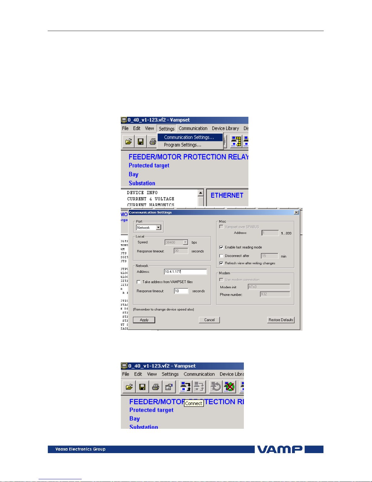
Change the Communication settings of the VAMPSET software
as shown in Figure 3.3-1. Set parameter Port = Network and
set the Network Address = IP Address selected in the relay
settings. Press “Apply” button and then activate Connection to
the relay (see Figure 3.3-2).
Figure 3.3-1 Changing the communication settings of the VAMPSET
software
Figure 3.3-2 Button for activating connection to the relay
VMVEAi.EN001
Vamp 24h support phone : +358 (0)20 753 3264
11
Page 12
VEA 3CGi Ethernet adapter
User’s manual
VAMP Ltd
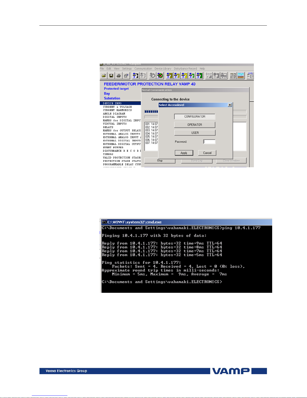
After activating the connection to the relay the normal
connection opening window as shown in Figure 3.3-3 should
pop up.
Figure 3.3-3 VAMPSET connection opening window
The communication with the VEA 3CGi can also be tested
using “ping” command via the DOS-window of the Windows
operating system (see Figure 3.3-4 ).
Figure 3.3-4 Testing connection to the VEA 3CGi with the " ping" command.
12
Vamp 24h support phone : +358 (0)20 753 3264
VMVEAi.EN001
Page 13
VAMP Ltd Ethernet adapter
User’s manual
VEA 3CGi
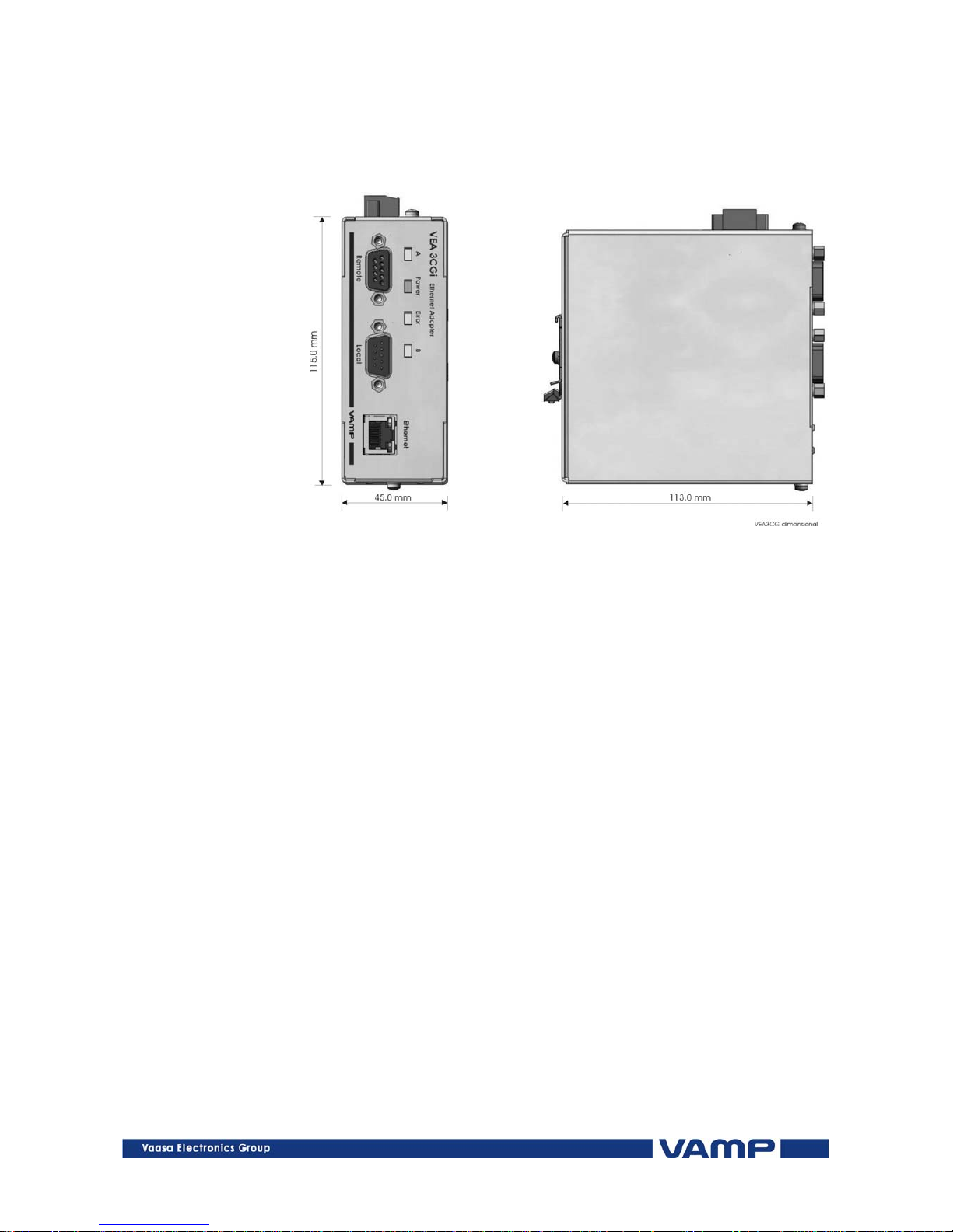
4. Dimensional drawing
Figure. 4-1 Ethernet adapter VEA 3CGi dimensions
VMVEAi.EN001
Vamp 24h support phone : +358 (0)20 753 3264
13
Page 14

VEA 3CGi Ethernet adapter
User’s manual
VAMP Ltd
5. Firmware update of VEA 3CGi
The firmware of the VEA 3CGi module can be updated using
Vampset PC software. For the update procedure a PC with
Vampset software and a firmware file for the adapter is
needed. The file can be obtained by contacting
[email protected]. The adapter to be updated must be
disconnected from the network and from the relay. An external
power supply of DC 12-24V must be connected and a nullmodem cable should be connected between the serial port of the
PC and the remote port of the adapter.
From Vampset menu communication select Update Firmware
and follow the instructions given by Vampset. The adapter is
expecting the communication speed of the serial link to be
38400 bps.
After the update procedure has finished, remove the external
power supply and reconnect the adapter to the relay.
14
Vamp 24h support phone : +358 (0)20 753 3264
VMVEAi.EN001
Page 15

VAMP Ltd Ethernet adapter
User’s manual
VEA 3CGi
VMVEAi.EN001
6. Reference information
Documentation:
VAMPSET User’s Manual VMV.EN0xx
Manufacturer data:
VAMP Ltd.
P.O.Box 810
FIN-65101 Vaasa, Finland
Visiting address: Yrittäjänkatu 15
Phone: +358 (0)20 753 3200
Fax: +358 (0)20 753 3205
URL: http://www.vamp.fi
Service:
VAMP Ltd.
P.O.Box 810
FIN-65101 Vaasa, Finland
Visiting address: Yrittäjänkatu 15
Phone: +358 (0)20 753 3200
Fax: +358 (0)20 753 3205
24h support phone:
Phone: +358 (0)20 753 3264
Email: [email protected]
Vamp 24h support phone : +358 (0)20 753 3264
15
Page 16

We
reserve the rights to changes without prior notice
VAMP Ltd Street address: Yrittäjänkatu 15 Phone: +358 20 753 3200
Post address: Fax: +358 20 753 3205
P.O Box 810, FIN 65101 Vaasa, Internet: www.vamp.fi
Finland Email: [email protected]
VMVEAi.EN001
 Loading...