

Page 1
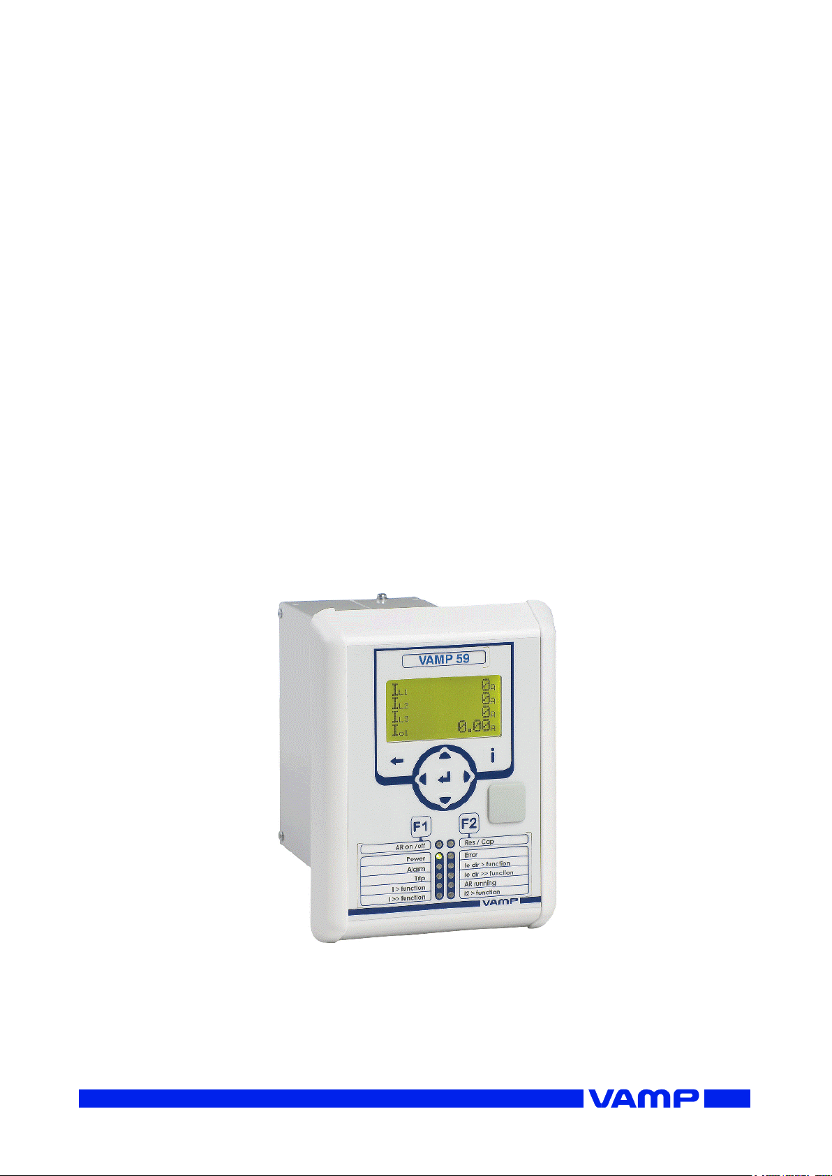
VAMP 59
Line differential protection relay
Operation and configuration
instructions
Technical description
Page 2

2
VM59.EN001
Page 3

Operation and configuration
Table of Contents
VM59.EN001
VAMP 24h support phone +358 (0)20 753 3264
3
Table of Contents
1. General ................................................................................... 4
1.1. Relay features ..................................................................... 4
1.2. User interface ...................................................................... 5
1.3. Operating Safety ................................................................ 5
2. Local panel user interface .................................................... 6
2.1. Relay front panel ................................................................ 6
2.1.1. Display ......................................................................... 7
2.1.2. Menu navigation and pointers ................................ 8
2.1.3. Keypad ........................................................................ 9
2.1.4. Operation indicators .............................................. 10
2.1.5. Adjusting display contrast ..................................... 10
2.2. Local panel operations .................................................. 11
2.2.1. Navigating in menus .............................................. 11
2.2.2. Menu structure of protection functions .............. 15
2.2.3. Setting groups ......................................................... 18
2.2.4. Fault logs .................................................................. 19
2.2.5. Operating levels ...................................................... 20
2.3. Operating measures ....................................................... 22
2.3.1. Control functions .................................................... 22
2.3.2. Measured data ....................................................... 23
2.3.3. Reading event register .......................................... 24
2.3.4. Forced control (Force) ........................................... 25
2.4. Configuration and parameter setting ......................... 26
2.4.1. Parameter setting ................................................... 27
2.4.2. Setting range limits ................................................. 28
2.4.3. Disturbance recorder menu DR ........................... 28
2.4.4. Configuring digital inputs DI .................................. 29
2.4.5. Configuring digital outputs DO ............................ 29
2.4.6. Configuring analogue outputs AO (Option) ...... 30
2.4.7. Protection menu Prot ............................................. 30
2.4.8. Configuration menu CONF ................................... 31
2.4.9. Protocol menu Bus .................................................. 32
2.4.10. Single line diagram editing ................................... 35
2.4.11. Blocking and interlocking configuration ............. 35
3. VAMPSET PC software .......................................................... 36
Page 4
1.1 Relay features
1 General
Operation and configuration
4
VAMP 24h support phone +358 (0)20 753 3264
VM59.EN001
IEEE/ANSI
code
IEC symbol
Function name
87L
LdI>,
LdI>>
Line differential protection
87Lf2
Second harmonic blocking
87Lf5
Fifth harmonic blocking
50/51
3I>, 3I>>,
3I>>>
Overcurrent protection
50N/51N
I0>, I0>>,
I0>>>,
I0>>>>
Earth fault protection
49
T>
Thermal overload protection
50BF
CBFP
Circuit-breaker failure protection
46
I2>
Current unbalance protection
59N
U0>, U0>>
Zero sequence voltage protection
67N,
50N/51N
Directional or non directional.
earth-fault, low-set stage,
sensitive, definite or inverse time
79
AR
Auto-reclosing
99
Prg1…8
Programmable stages
51F2
If2>
Second harmonic O/C stage
51F5
If5>
Fifth harmonic O/C stage
1. General
This first part (Operation and configuration) of the publication
contains general descriptions of the functions, of the protection
relay as well as operation instructions. It also includes
instructions for parameterization and configuration of the relay
and instructions for changing settings.
The second part (Technical description) of the publication
includes detailed protection function descriptions as well as
application examples and technical data sheets.
The Mounting and Commissioning Instructions are published
in a separate publication with the code VMMC.EN0xx.
1.1. Relay features
The comprehensive protection functions of the relay make it
ideal for utility, industrial, marine and off-shore power
distribution applications. The relay features the following
protection functions.
List of protection functions
Page 5
Operation and configuration
1 General
1.2 User interface
VM59.EN001
VAMP 24h support phone +358 (0)20 753 3264
5
IEEE/ANSI
code
IEC symbol
Function name
50ARC/
50NARC
ArcI>,
ArcI01>
Optional arc fault protection (with
an external module)
Further the relay includes a disturbance recorder. Arc
protection is optionally available.
The relay communicates with other systems using common
protocols, such as the Modbus RTU, ModbusTCP, IEC 61850,
Ethernet / IP and DNP 3.0. An optional communication option
is required for this (see ordering code in technical description).
1.2. User interface
The relay can be controlled in three ways:
Locally with the push-buttons on the relay front panel
Locally using a PC connected to the USB port on the front
Via remote control over the optional remote control port on
the relay rear panel.
1.3. Operating Safety
The terminals on the rear panel of the relay may
carry dangerous voltages, even if the auxiliary
voltage is switched off. A live current transformer
secondary circuit must not be opened.
Disconnecting a live circuit may cause dangerous
voltages! Any operational measures must be carried out
according to national and local handling directives and
instructions.
Carefully read through all operation instructions before any
operational measures are carried out.
Page 6
2.1 Relay front panel
2 Local panel user interface
Operation and configuration
6
VAMP 24h support phone +358 (0)20 753 3264
VM59.EN001
2. Local panel user interface
2.1. Relay front panel
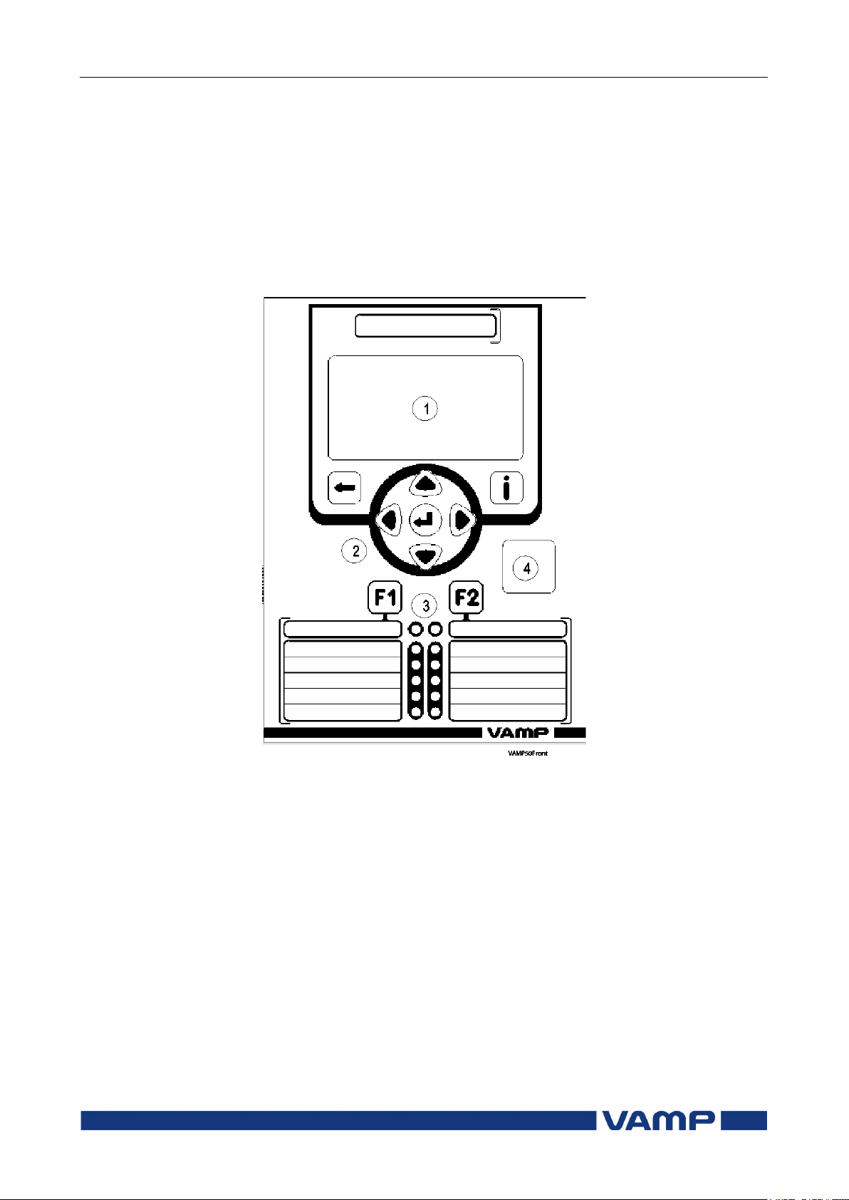
The figure below shows an example of the front panel of the
line differential protection relay VAMP 59 and the location of
the user interface elements used for local control.
Figure 2.1-1. Relay front panel
1. LCD dot matrix display
2. Keypad
3. LED indicators
4. USB communication port for PC
Page 7
Operation and configuration
2 Local panel user interface
2.1 Relay front panel
VM59.EN001
VAMP 24h support phone +358 (0)20 753 3264
7
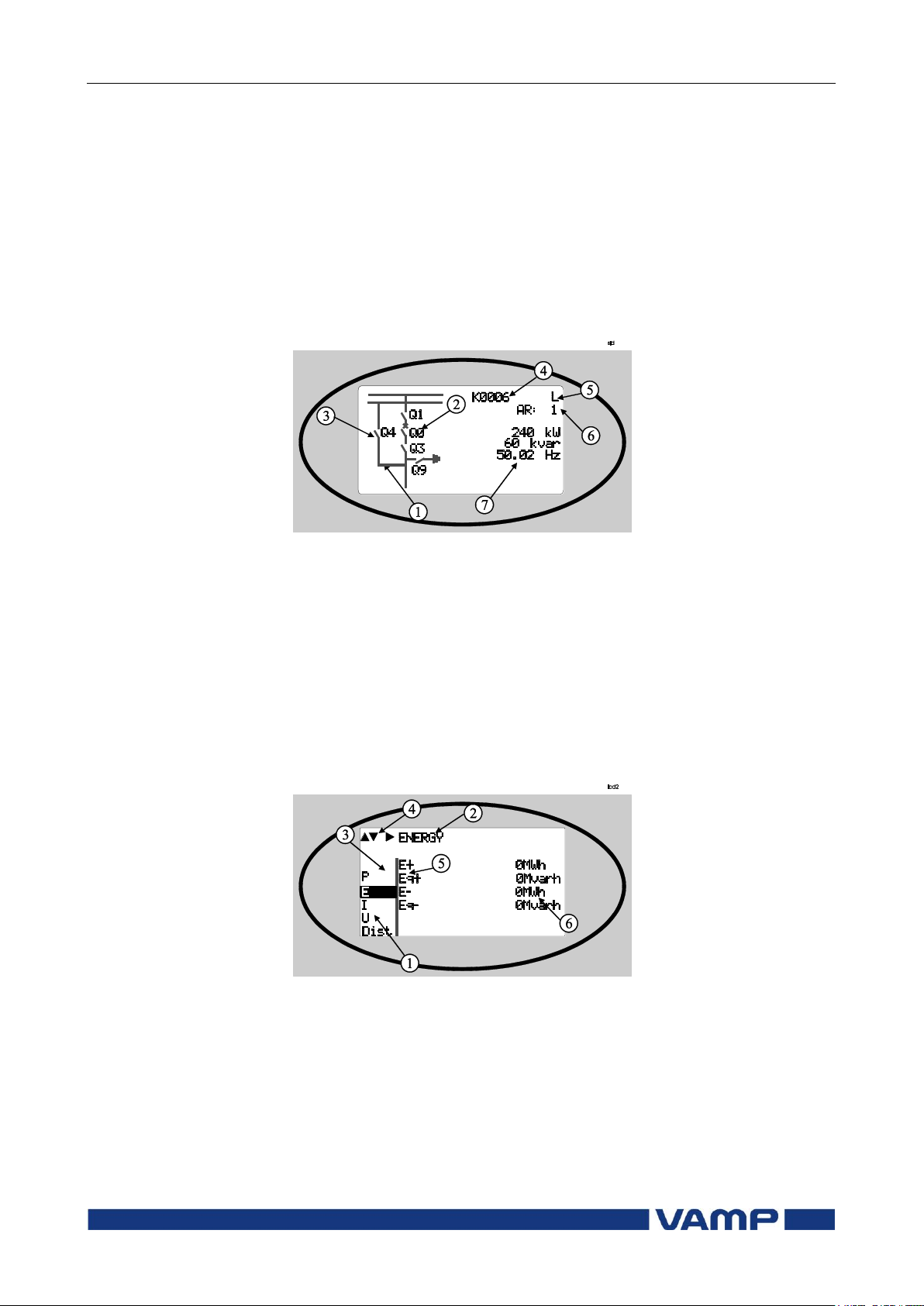
2.1.1. Display
The relay is provided with a backlighted 128x64 LCD dot
matrix display. The display enables showing 21 characters is
one row and eight rows at the same time. The display has two
different purposes: one is to show the single line diagram of the
relay with the object status, measurement values, identification
etc. (Figure 2.1.1-1). The other purpose is to show the
configuration and parameterization values of the relay (Figure
2.1.1-2).
Figure 2.1.1-1 Sections of the LCD dot matrix display
1. Freely configurable single-line diagram
2. Controllable objects (max six objects)
3. Object statuses (max eight objects)
4. Bay identification
5. Local/Remote selection
6. Auto-reclose on/off selection (if applicable)
7. Freely selectable measurement values (max. six values)
Figure 2.1.1-2 Sections of the LCD dot matrix display
1. Main menu column
2. The heading of the active menu
3. The cursor of the main menu
4. Possible navigating directions (push buttons)
5. Measured/setting parameter
6. Measured/set value
Page 8

2.1 Relay front panel
2 Local panel user interface
Operation and configuration
8
VAMP 24h support phone +358 (0)20 753 3264
VM59.EN001
Backlight control
Display backlight can be switched on with a digital input,
virtual input or virtual output. LOCALPANEL CONF/Display
backlight ctrl setting is used for selecting trigger input for
backlight control. When the selected input activates (rising
edge), display backlight is set on for 60 minutes.
2.1.2. Menu navigation and pointers
1. Use the arrow keys UP and DOWN to move up and down in
the main menu, that is, on the left-hand side of the display.
The active main menu option is indicated with a cursor. The
options in the main menu items are abbreviations, e.g. Evnt
= events.
2. After any selection, the arrow symbols in the upper left
corner of the display show the possible navigating directions
(applicable navigation keys) in the menu.
3. The name of the active submenu and a possible ANSI code
of the selected function are shown in the upper part of the
display, e.g. CURRENTS
4. Further, each display holds the measured values and units
of one or more quantities or parameters, e.g. Ilmax 300A.
Page 9
Operation and configuration
2 Local panel user interface
2.1 Relay front panel
VM59.EN001
VAMP 24h support phone +358 (0)20 753 3264
9
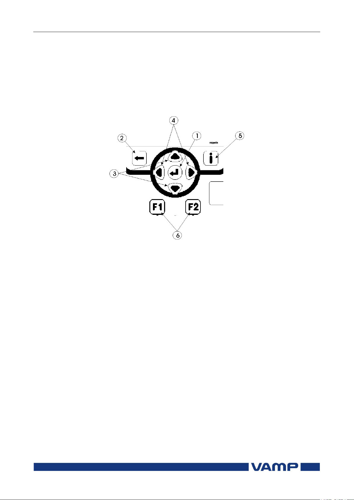
2.1.3. Keypad
You can navigate in the menu and set the required parameter
values using the keypad and the guidance given in the display.
Furthermore, the keypad is used to control objects and switches
on the single line diagram display. The keypad is composed of
four arrow keys, one cancel key, one enter key, one info key and
two configurable function keys.
Figure 2.1.3-1 Keys on the keypad
1. Enter and confirmation key (ENTER)
2. Cancel key (CANCEL)
3. Up/Down [Increase/Decrease] arrow keys (UP/DOWN)
4. Keys for selecting submenus [selecting a digit in a
numerical value] (LEFT/RIGHT)
5. Additional information key (INFO)
6. Function keys 1 and 2 (F1 / F2)
As default F1 toggles Virtual Input 1 (VI1) On/Off
As default F2 toggles Virtual Input 2 (VI2) On/Off
Instructions about programming F1 / F2, see chapter 5.4
Function keys / F1 & F2 in the technical description.
NOTE! The term, which is used for the buttons in this manual, is
inside the brackets.
Page 10
2.1 Relay front panel
2 Local panel user interface
Operation and configuration
10
VAMP 24h support phone +358 (0)20 753 3264
VM59.EN001
LED indicator
Meaning
Measure/ Remarks
Power LED lit
The auxiliary power has
been switched on
Normal operation state
Error LED lit
Internal fault, operates in
parallel with the self
supervision output relay
The relay attempts to
reboot [REBOOT]. If the
error LED remains lit,
call for maintenance.
A- H LED lit
Application-related status
indicators.
Configurable
F1 / F2 LED lit
Corresponding function
key pressed / activated
Depending of function
programmed to F1 / F2
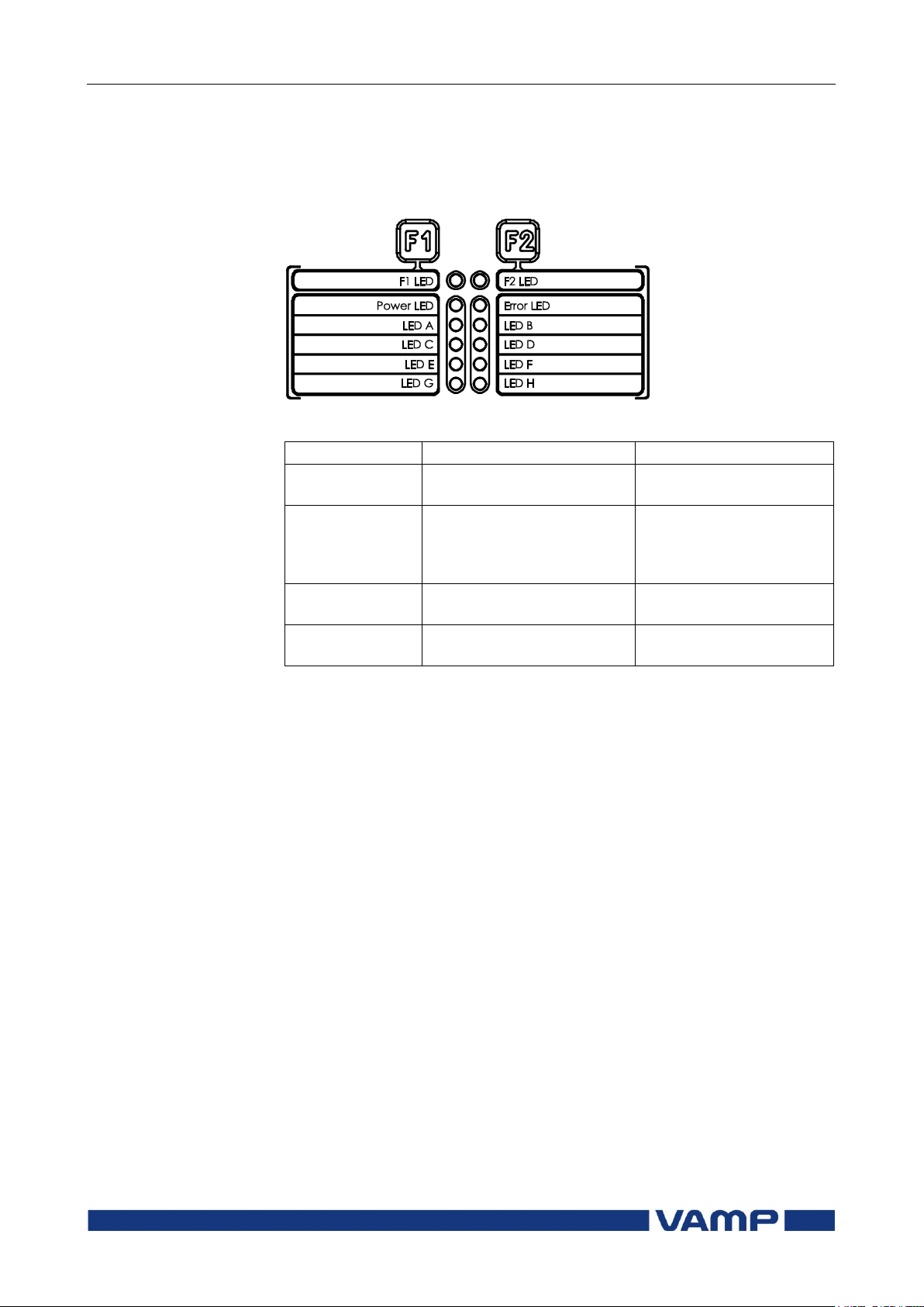
2.1.4. Operation indicators
The relay is provided with twelve LED indicators:
Figure 2.1.4-1. Operation indicators of the relay
Resetting latched indicators and output relays
All the indicators and output relays can be given a latching
function in the configuration.
There are several ways to reset latched indicators and relays:
From the alarm list, move back to the initial display by
pushing the CANCEL key for approx. 3s. Then reset the
latched indicators and output relays by pushing the ENTER
key.
Acknowledge each event in the alarm list one by one by
pushing the ENTER key equivalent times. Then, in the
initial display, reset the latched indicators and output
relays by pushing the ENTER key.
The latched indicators and relays can also be reset via a remote
communication bus or via a digital input configured for that
purpose.
2.1.5. Adjusting display contrast
The readability of the LCD varies with the brightness and the
temperature of the environment. The contrast of the display
can be adjusted via the PC user interface, see chapter 3.
Page 11
Operation and configuration
2 Local panel user interface
2.2 Local panel operations
VM59.EN001
VAMP 24h support phone +358 (0)20 753 3264
11
2.2. Local panel operations
The front panel can be used to control objects, change the local/
remote status, read the measured values, set parameters, and
to configure relay functions. Some parameters, however, can
only be set by means of a PC connected to the local
communication port. Some parameters are factory-set.
2.2.1. Navigating in menus
All the menu functions are based on the main menu/submenu
structure:
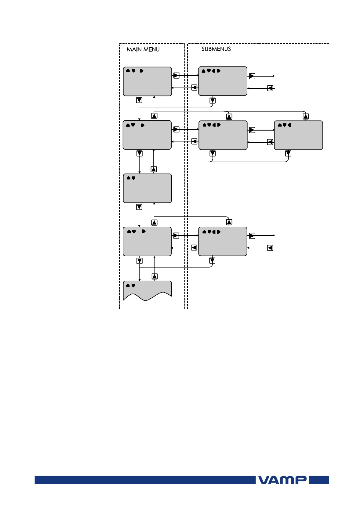
1. Use the arrow keys UP and DOWN to move up and down in
the main menu.
2. To move to a submenu, repeatedly push the RIGHT key
until the required submenu is shown. Correspondingly,
push the LEFT key to return to the main menu.
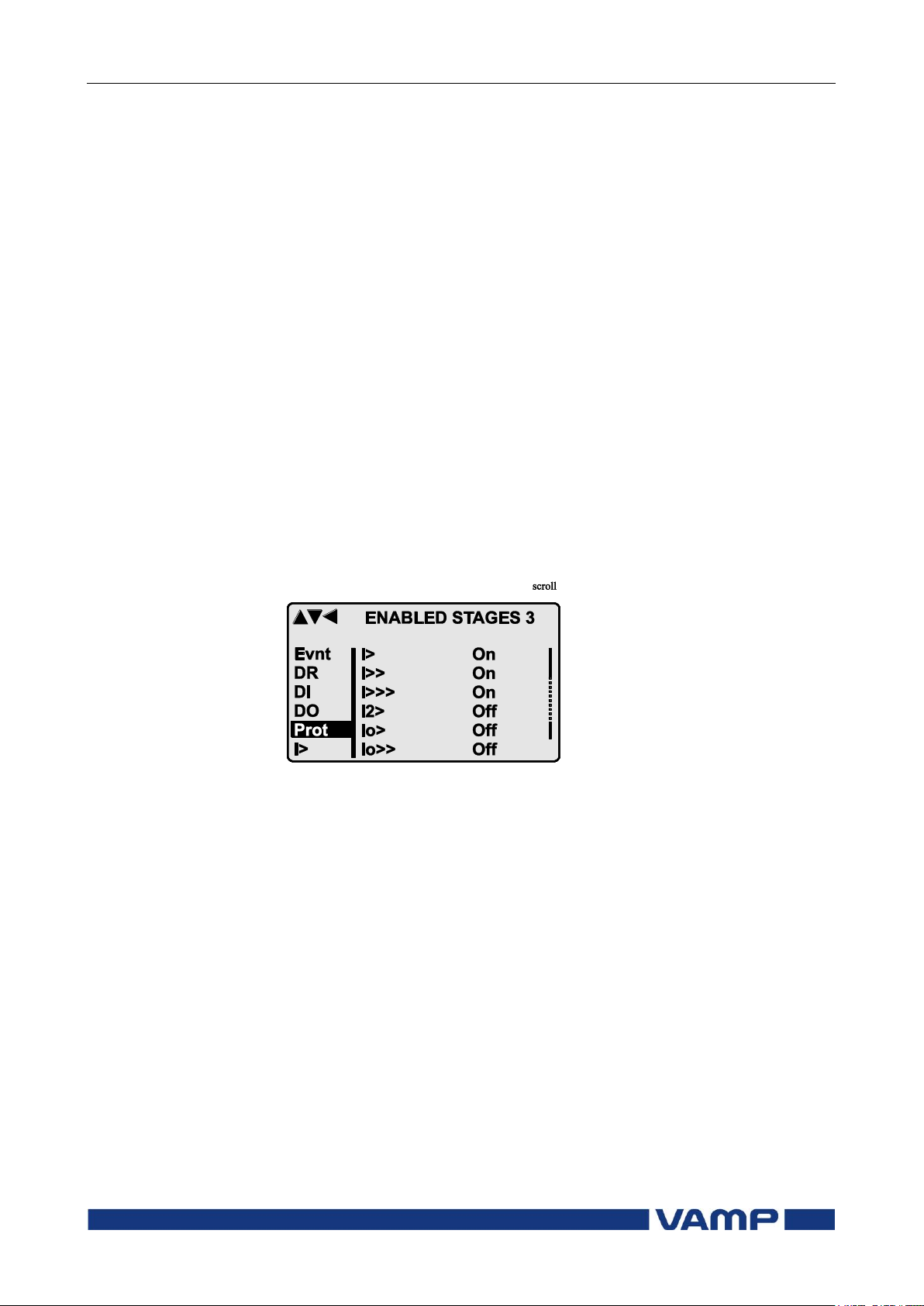
3. Push the ENTER key to confirm the selected submenu. If
there are more than six items in the selected submenu, a
black line appears to the right side of the display (Figure
2.2.1-1). It is then possible to scroll down in the submenu.
Figure 2.2.1-1 Example of scroll indication
4. Push the CANCEL key to cancel a selection.
5. Hold the CANCEL key pushed for appr. 4 sec. to display the
title screen.
6. Pushing the UP or DOWN key in any position of a
submenu, when it is not selected, brings you directly one
step up or down in the main menu.
The active main menu selection is indicated with black
background color. The possible navigating directions in the
menu are shown in the upper-left corner by means of black
triangular symbols.
Page 12
2.2 Local panel operations
2 Local panel user interface
Operation and configuration
12
VAMP 24h support phone +358 (0)20 753 3264
VM59.EN001
Figure 2.2.1-2 Principles of the menu structure and navigation in the menus
7. Push the INFO key and then the ENTER key to give the
password.
8. Push the INFO key to obtain additional information about
any menu item.
9. Push the CANCEL key to revert to the normal display.
Page 13

Operation and configuration
2 Local panel user interface
2.2 Local panel operations
VM59.EN001
VAMP 24h support phone +358 (0)20 753 3264
13
Main menu
Number
of
menus
Description
ANSI
code
Note
1 Interactive mimic display
1
5 Double size measurements
defined by the user
1
1 Title screen with device name,
time and firmware version.
Meas
14
Measurements
Imax
5
Time stamped min & max of
currents
Mont
17
Maximum values of the last 31
days and the last twelve
months
Evnt
2
Events
DR 3 Disturbance recorder
2
Runh
2
Running hour counter. Active
time of a selected digital input
and time stamps of the latest
start and stop.
TIMR
6
Day and week timers
DI 5 Digital inputs including virtual
inputs
DO 4 Digital outputs (relays) and
output matrix
AO 2 Visible only when AO card
installed
Prot
9
Protection counters, combined
overcurrent status, protection
status, protection enabling, cold
load and inrush detectionIf2>
and block matrix
MSTAT
1
Motor status
LdI>
4
1st line differential stage
87L
4
LdI>>
4
2nd line differential stage
87L
4
I> 5 1st overcurrent stage
50/51
4
I>> 3 2nd overcurrent stage
50/51
4
I>>>
3
3rd overcurrent stage
50/51
4
I2> 3 Current unbalance stage
46 4 T> 3 Thermal overload stage
49 4 If2>
3
Second harmonic O/C stage
51F2
4
If5>
3
Fifth harmonic O/C stage
51F5
4
Io> 5 1st earth fault stage
50N/51N
4
Main menu
The general menu structure is shown in Figure 2.2.1-2. The
menu is dependent on the user’s configuration and the options
according the order code. For example only the enabled
protection stages will appear in the menu.
A list of the local main menu
Page 14
2.2 Local panel operations
2 Local panel user interface
Operation and configuration
14
VAMP 24h support phone +358 (0)20 753 3264
VM59.EN001
Main
menu
Number
of
menus
Description
ANSI
code
Note
Io>>
3
2nd earth fault stage
50N/51N
4
Io>>>
3
3rd earth fault stage
50N/51N
4
Io>>>>
3
4th earth fault stage
50N/51N
4
Io >
6
1st directional earth fault stage
67N
4
Io >>
7
2nd directional earth fault stage
67N
4
Uo>
3
1st residual overvoltage stage
59N
4
Uo>>
3
2nd residual overvoltage stage
59N
4
Prg1
3
1st programmable stage
4 Prg2
3
2nd programmable stage
4 Prg3
3
3rd programmable stage
4 Prg4
3
4th programmable stage
4 Prg5
3
5th programmable stage
4 Prg6
3
6th programmable stage
4 Prg7
3
7th programmable stage
4 Prg8
3
8th programmable stage
4
CBFP
3
Circuit breaker failure
protection
50BF
4
CBWE
5
Circuit breaker wearing
supervision
4
CTSV
1
CT supervisor
4
ArcI>
11
Optional arc protection stage
for phase-to-phase faults and
delayed light signal.
50ARC
4
ArcIo>
10
Optional arc protection stage
for earth faults. Current input
= I01
50NARC
4
AR 4 Auto-reclose
79 OBJ
11
Object definitions
5
Lgic
2
Status and counters of user’s
logic
1
CONF
9
Device setup, scaling etc.
6
Bus
11
Serial port and protocol
configuration
7
OPT
1
Option cards
Diag
9
Device selfdiagnosis
1
Configuration is done with VAMPSET
2
Recording files are read with VAMPSET
3
The menu is visible only if protocol "ExternalIO" is selected for one of
the serial ports. Serial ports are configured in menu "Bus".
4
The menu is visible only if the stage is enabled.
5
Objects are circuit breakers, disconnectors etc.
6
There are two extra menus, which are visible only if the access level
"operator" or "configurator" has been opened with the corresponding
password.
7
Detailed protocol configuration is done with VAMPSET.
Notes
Page 15
Operation and configuration
2 Local panel user interface
2.2 Local panel operations
VM59.EN001
VAMP 24h support phone +358 (0)20 753 3264
15
Menu structure of protection functions
The general structure of all protection function menus is
similar although the details do differ from stage to stage. As an
example the details of the second overcurrent stage I>> menus
are shown below.
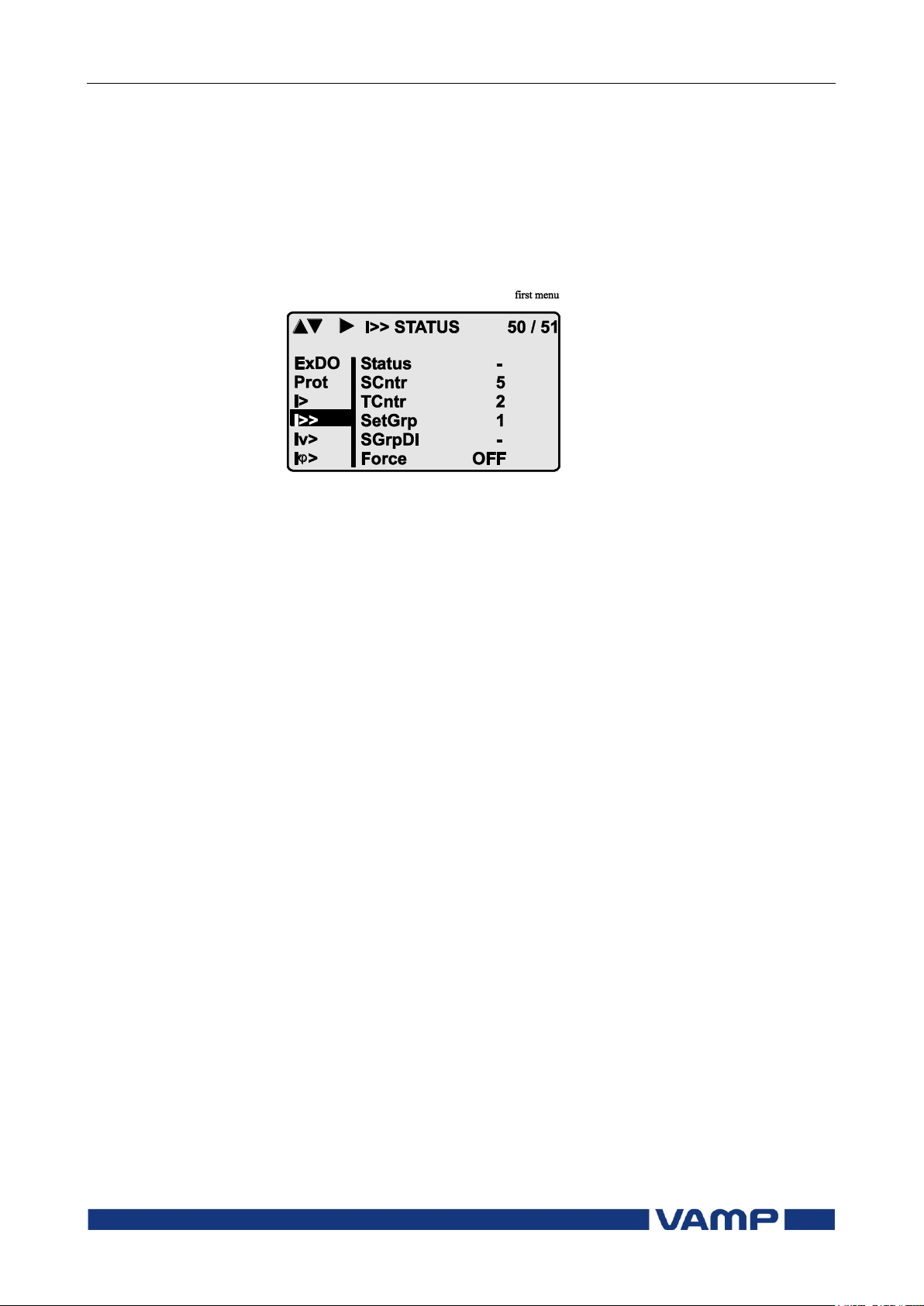
First menu of I>> 50/51 stage
Figure 0-1 First menu of I>> 50/51 stage
This is the status, start and trip counter and setting group
menu. The content is:
Status –
The stage is not detecting any fault at the moment. The
stage can also be forced to pick-up or trip is the operating
level is “Configurator” and the force flag below is on.
Operating levels are explained in chapter 2.2.5
SCntr 5
The stage has picked-up a fault five times since the last
reset or restart. This value can be cleared if the operating
level is at least “Operator”.
TCntr 2
The stage has tripped two times since the last reset or
restart. This value can be cleared if the operating level is at
least “Operator”.
SetGrp 1
The active setting group is one. This value can be edited if
the operating level is at least “Operator”. Setting groups are
explained in chapter 2.2.3.
SGrpDI –
The setting group is not controlled by any digital input. This
value can be edited if the operating level is at least
“Configurator”.
Force Off
The status forcing and output relay forcing is disabled. This
force flag status can be set to “On” or back to “Off” if the
operating level is at least “Configurator”. If no front panel
Page 16
2.2 Local panel operations
2 Local panel user interface
Operation and configuration
16
VAMP 24h support phone +358 (0)20 753 3264
VM59.EN001
button is pressed within five minutes and there is no
VAMPSET communication, the force flag will be set to “Off”
position. The forcing is explained in Chapter 2.3.4.
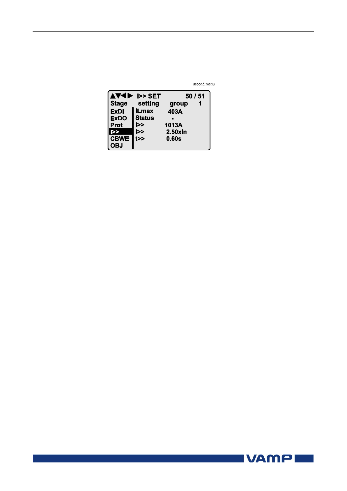
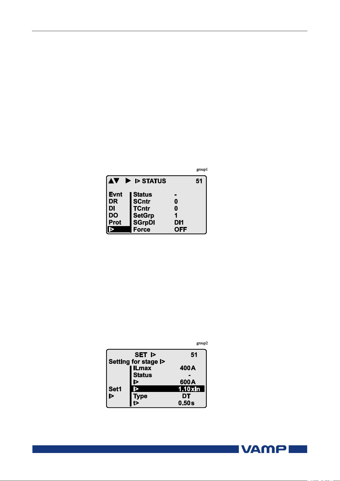
Second menu of I>> 50/51 stage
Figure 0-2 Second menu(next on the right) of I>> 50/51 stage
This is the main setting menu. The content is:
Stage setting group 1
These are the group 1 setting values. The other setting
group can be seen by pressing push buttons ENTER and
then RIGHT or LEFT. Setting groups are explained in
chapter 2.2.3.
ILmax 403A
The maximum of three measured phase currents is at the
moment 403 A. This is the value the stage is supervising.
Status –
Status of the stage. This is just a copy of the status value in
the first menu.
I>> 1013 A
The pick-up limit is 1013 A in primary value.
I>> 2.50xIn
The pick-up limit is 2.50 times the rated current of the
generator. This value can be edited if the operating level is
at least “Operator”. Operating levels are explained in
chapter 2.2.5.
t>> 0.60s
The total operation delay is set to 600 ms. This value can be
edited if the operating level is at least “Operator”.
Page 17
Operation and configuration
2 Local panel user interface
2.2 Local panel operations
VM59.EN001
VAMP 24h support phone +358 (0)20 753 3264
17
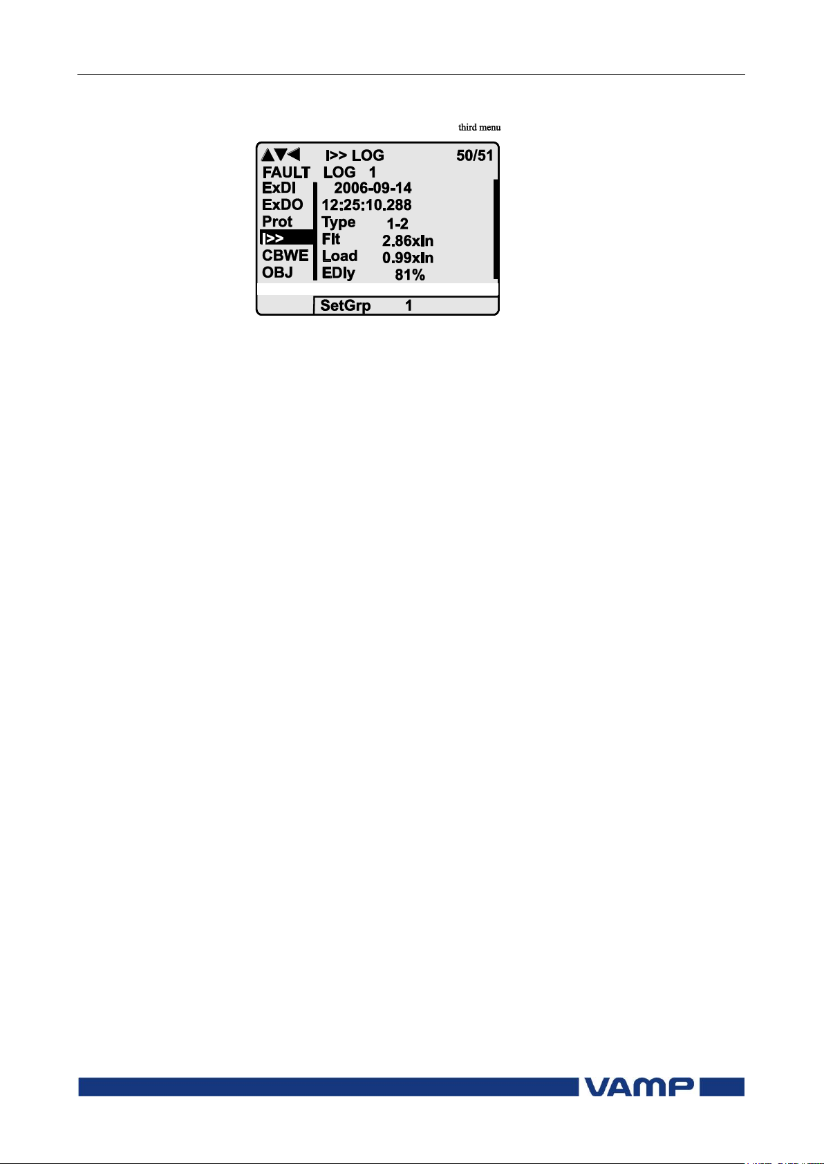
Third menu of I>> 50/51 stage
Figure 0-3 Third and last menu (next on the right) of I>> 50/51 stage
This is the menu for registered values by the I>> stage. Fault
logs are explained in chapter 2.2.4.
FAULT LOG 1
This is the latest of the eight available logs. You may move
between the logs by pressing push buttons ENTER and then
RIGHT or LEFT.
2006-09-14
Date of the log.
12:25:10.288
Time of the log.
Type 1-2
The overcurrent fault has been detected in phases L1 and
L2 (A & B, red & yellow, R/S, u&v).
Flt 2.86xIn
The fault current has been 2.86 per unit.
Load 0.99xIn
The average load current before the fault has been 0.99 pu.
EDly 81%
The elapsed operation delay has been 81% of the setting
0.60 s = 0.49 s. Any registered elapsed delay less than 100 %
means that the stage has not tripped, because the fault
duration has been shorter that the delay setting.
SetGrp 1
The setting group has been 1. This line can be reached by
pressing ENTER and several times the DOWN button.
Page 18
2.2 Local panel operations
2 Local panel user interface
Operation and configuration
18
VAMP 24h support phone +358 (0)20 753 3264
VM59.EN001
2.2.2. Setting groups
Most of the protection functions of the relay have two setting
groups. These groups are useful for example when the network
topology is changed frequently. The active group can be
changed by a digital input, through remote communication or
locally by using the local panel.
The active setting group of each protection function can be
selected separately. Figure 2.2.2-1 shows an example where the
changing of the I> setting group is handled with digital input
one (SGrpDI). If the digital input is TRUE, the active setting
group is group two and correspondingly, the active group is
group one, if the digital input is FALSE. If no digital input is
selected (SGrpDI = -), the active group can be selected by
changing the value of the parameter SetGrp.
Figure 2.2.2-1 Example of protection submenu with setting group
parameters
The changing of the setting parameters can be done easily.
When the desired submenu has been found (with the arrow
keys), press the ENTER key to select the submenu. Now the
selected setting group is indicated in the down-left corner of the
display (See Figure 2.2.3.-2). Set1 is setting group one and Set2
is setting group two. When the needed changes, to the selected
setting group, have been done, press the LEFT or the RIGHT
key to select another group (the LEFT key is used when the
active setting group is 2 and the RIGHT key is used when the
active setting group is 1).
Figure 2.2.2-2 Example of I> setting submenu
Page 19
Operation and configuration
2 Local panel user interface
2.2 Local panel operations
VM59.EN001
VAMP 24h support phone +358 (0)20 753 3264
19
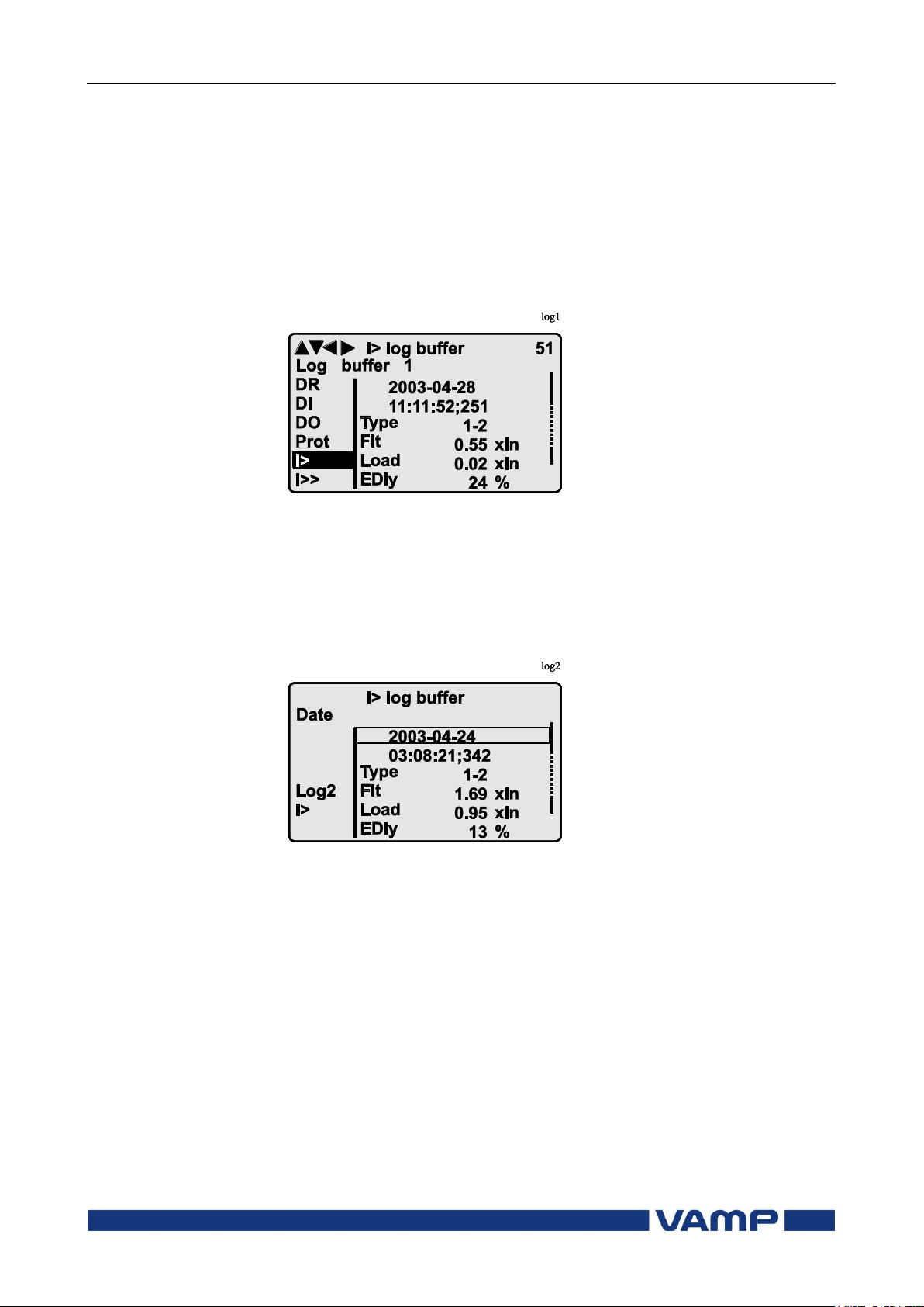
2.2.3. Fault logs
All the protection functions include fault logs. The fault log of a
function can register up to eight different faults with time
stamp information, fault values etc. The fault logs are stored in
non-volatile memory. Each function has its own logs. The fault
logs are not cleared when power is switched off. The user is
able to clear all logs using VAMPSET. Each function has its
own logs (See Figure 2.2.4-1).
Figure 2.2.3-1 Example of fault log
To see the values of, for example, log two, press then ENTER
key to select the current log (log one). The current log number
is then indicated in the down-left corner of the display (See
Figure 2.2.4-2, Log2 = log two). The log two is selected by
pressing the RIGHT key once.
Figure 2.2.3-2 Example of selected fault log
Page 20

2.2 Local panel operations
2 Local panel user interface
Operation and configuration
20
VAMP 24h support phone +358 (0)20 753 3264
VM59.EN001
Use:
Possible to read e.g. parameter values,
measurements and events
Opening:
Level permanently open
Closing:
Closing not possible
Use:
Possible to control objects and to change e.g.
the settings of the protection stages
Opening:
Default password is 1
Setting state:
Push ENTER
Closing:
The level is automatically closed after 10
minutes idle time. Giving the password 9999
can also close the level.
Use:
The configurator level is needed during the
commissioning of the relay. E.g. the scaling of
the voltage and current transformers can be
set.
Opening:
Default password is 2
Setting state:
Push ENTER
Closing:
The level is automatically closed after 10
minutes idle time. Giving the password 9999
can also close the level.
2.2.4. Operating levels
The relay has three operating levels: User level, Operator level
and Configurator level. The purpose of the access levels is to
prevent accidental change of relay configurations, parameters
or settings.
USER level
OPERATOR level
CONFIGURATOR level
Page 21
Operation and configuration
2 Local panel user interface
2.2 Local panel operations
VM59.EN001
VAMP 24h support phone +358 (0)20 753 3264
21
Command
Description
get pwd_break
Get the break code (Example:
6569403)
get serno
Get the serial number of the relay
(Example: 12345)
Command
Description
set pwd_break=4435876
Restore the factory default
passwords (“4435876” is just an
example. The actual code should be
asked from VAMP Ltd.)
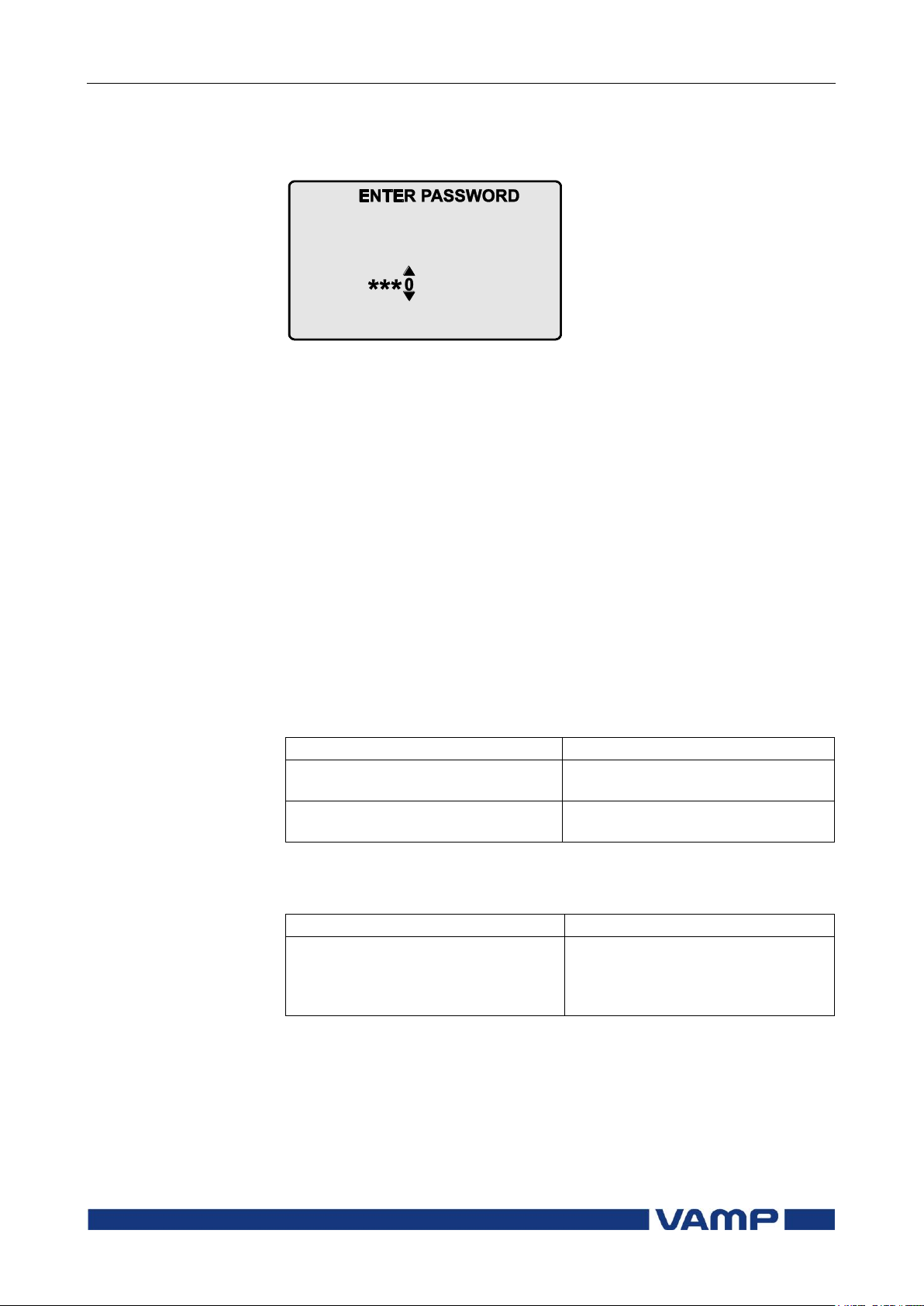
Opening access
1. Push the INFO key and the ENTER key on the front panel
Figure 2.2.4-1 Opening the access level
2. Enter the password needed for the desired level: the
password can contain four digits. The digits are supplied
one by one by first moving to the position of the digit using
the RIGHT key and then setting the desired digit value
using the UP key.
3. Push the ENTER key.
Password handling
The passwords can only be changed using VAMPSET software
connected to the USB -port in front of the relay.
It is possible to restore the password(s) in case the password is
lost or forgotten. In order to restore the password(s), a relay
program is needed. The virtual serial port settings are 38400
bps, 8 data bits, no parity and one stop bit. The bit rate is
configurable via the front panel.
Send both the numbers to [email protected] and ask for a
password break. A device specific break code is sent back to
you. That code will be valid for the next two weeks.
Now the passwords are restored to the default values (See
chapter 2.2.4).
Page 22

2.3 Operating measures
2 Local panel user interface
Operation and configuration
22
VAMP 24h support phone +358 (0)20 753 3264
VM59.EN001
2.3. Operating measures
2.3.1. Control functions
The default display of the local panel is a single-line diagram
including relay identification, Local/Remote indication, Autoreclose on/off selection and selected analogue measurement
values.
Please note that the operator password must be active in order
to be able to control the objects. Please refer to page 21 opening
access.
Toggling Local/Remote control
1. Push the ENTER key. The previously activated object starts
to blink.
2. Select the Local/Remote object (“L” or “R” squared) by using
the arrow keys.
3. Push the ENTER key. The L/R dialog opens. Select
“REMOTE” to enable remote control and disable local
control. Select “LOCAL” to enable local control and disable
remote control.
4. Confirm the setting by pushing the ENTER key. The
Local/Remote state will change.
Object control
Using ENTER and UP / DOWN keys
1. Push the ENTER key. The previously activated object starts
to blink.
2. Select the object to control by using the arrow keys. Please
note that only controllable objects can be selected.
3. Push the ENTER key. A control dialog opens.
4. Select the “Open” or “Close” command by using the UP and
DOWN arrow keys.
5. Confirm the operation by pushing the ENTER key. The
state of the object changes.
Page 23

Operation and configuration
2 Local panel user interface
2.3 Operating measures
VM59.EN001
VAMP 24h support phone +358 (0)20 753 3264
23
Value
Menu/Submenu
Description
IL1
MEAS/PHASE CURRENTS
Phase current IL1 [A]
IL2
MEAS/PHASE CURRENTS
Phase current IL2 [A]
IL3
MEAS/PHASE CURRENTS
Phase current IL3 [A]
IL1da
MEAS /PHASE
CURRENTS
15 min average for IL1 [A]
IL2da
MEAS /PHASE
CURRENTS
15 min average for IL2 [A]
IL3da
MEAS /PHASE
CURRENTS
15 min average for IL3 [A]
Io
MEAS /SYMMETRIC
CURRENTS
Primary value of zerosequence/
residual current Io [A]
IoC
MEAS /SYMMETRIC
CURRENTS
Calculated Io [A]
I1
MEAS /SYMMETRIC
CURRENTS
Positive sequence current [A]
I2
MEAS /SYMMETRIC
CURRENTS
Negative sequence current [A]
I2/I1
MEAS /SYMMETRIC
CURRENTS
Negative sequence current related
to positive sequence current (for
unbalance protection) [%]
Uo
MEAS/MISCELLANEOUS
Zero sequence voltage Uo [%]
f
MEAS/MISCELLANEOUS
Frequency [Hz]
AngDiag
MEAS/ANGEE DIAGRAM
Phasors
THDIL
MEAS /HARM.
DISTORTION
Total harmonic distortion of the
mean value of phase currents [%]
THDIL1
MEAS /HARM.
DISTORTION
Total harmonic distortion of phase
current IL1 [%]
THDIL2
MEAS /HARM.
DISTORTION
Total harmonic distortion of phase
current IL2 [%]
Using F1 & F2 in object control mode
1. Push F1 / F2 key. Object assigned to the key starts to blink
and a control dialog opens.
2. Confirm the operation by pushing the ENTER key.
Toggling virtual inputs
1. Push the ENTER key. The previously activated object starts
to blink.
2. Select the virtual input object (empty or black square)
3. The dialog opens
4. Select “VIon” to activate the virtual input or select “VIoff” to
deactivate the virtual input
2.3.2. Measured data
The measured values can be read from the Meas menu and its
submenus. Furthermore, any measurement value in the
following table can be displayed on the main view next to the
single line diagram. Up to six measurements can be shown.
Page 24
2.3 Operating measures
2 Local panel user interface
Operation and configuration
24
VAMP 24h support phone +358 (0)20 753 3264
VM59.EN001
Value
Menu/Submenu
Description
THDIL3
MEAS /HARM.
DISTORTION
Total harmonic distortion of phase
current IL3 [%]
IL1har
MEAS/HARMONICS of IL1
Harmonics of phase current IL1 [%]
IL2har
MEAS/HARMONICS of IL2
Harmonics of phase current IL2 [%]
IL3har
MEAS/HARMONICS of IL3
Harmonics of phase current IL3 [%]
IL1 wave
MEAS/IL1 WAVEFORM
Waveform of IL1
IL2 wave
MEAS/IL2 WAVEFORM
Waveform of IL2
IL3 wave
MEAS/IL3 WAVEFORM
Waveform of IL3
IL1 avg
MEAS/IL1 AVERAGE
10 min average of IL1
IL2 avg
MEAS/IL2 AVERAGE
10 min average of IL2
IL3 avg
MEAS/IL3 AVERAGE
10 min average of IL3
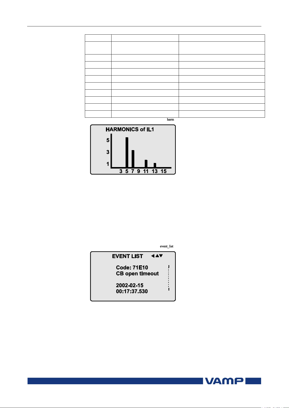
Figure 2.3.2-1. Example of harmonics bar display
2.3.3. Reading event register
The event register can be read from the Evnt submenu:
1. Push the RIGHT key once.
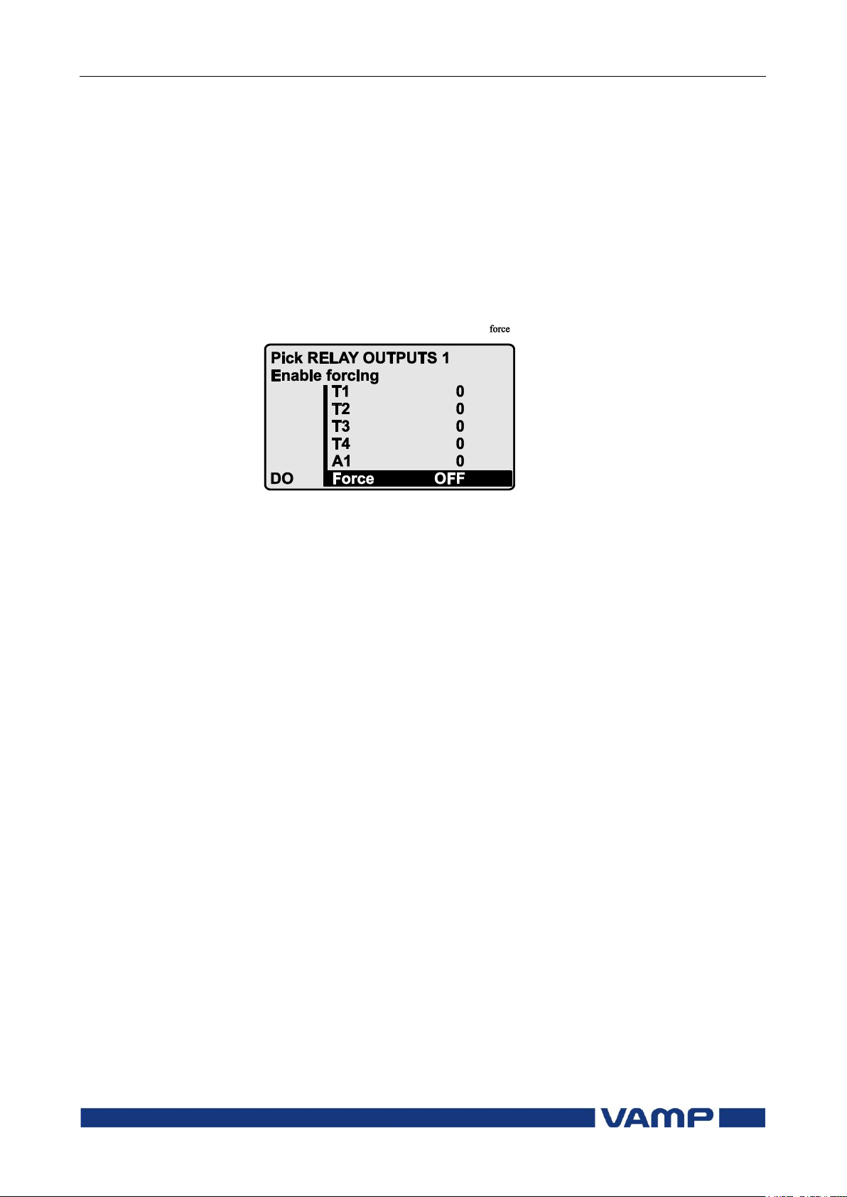
2. The EVENT LIST appears. The display contains a list of all
the events that have been configured to be included in the
event register.
Figure 2.3.3-1. Example of an event register
3. Scroll through the event list with the UP and DOWN keys.
4. Exit the event list by pushing the LEFT key.
It is possible to set the order in which the events are sorted. If
the “Order” -parameter is set to “New-Old”, then the first event
in the EVENT LIST is the most recent event.
Page 25
Operation and configuration
2 Local panel user interface
2.3 Operating measures
VM59.EN001
VAMP 24h support phone +358 (0)20 753 3264
25
2.3.4. Forced control (Force)
In some menus it is possible to switch a function on and off by
using a force function. This feature can be used, for instance,
for testing a certain function. The force function can be
activated as follows:
1. Move to the setting state of the desired function, for
example DO (see chapter 2.4, on page 26).
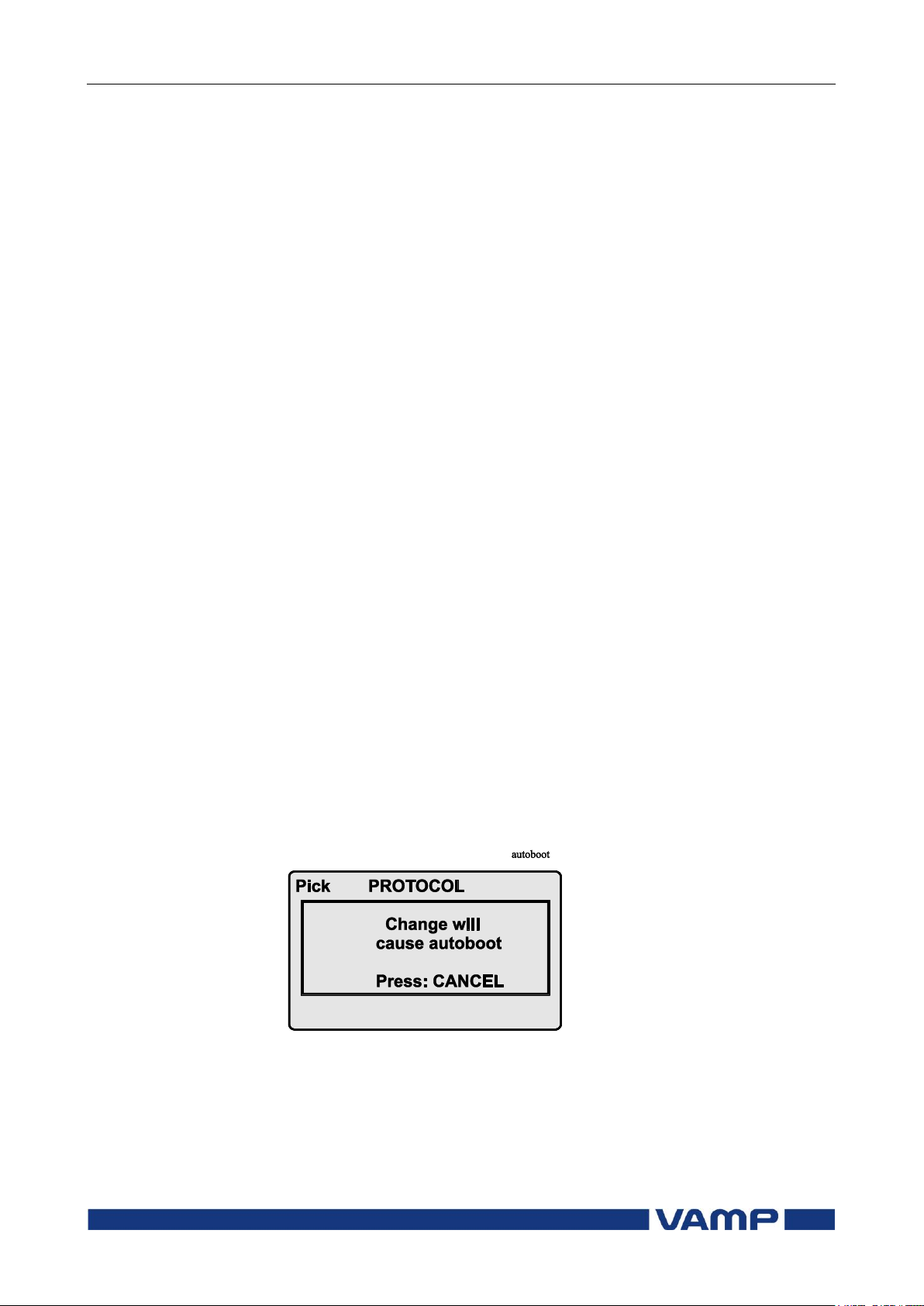
2. Select the Force function (the background color of the force
text is black).
Figure 2.3.4-1 Selecting Force function
3. Push the ENTER key.
4. Push the UP or DOWN key to change the "OFF" text to
"ON", that is, to activate the Force function.
5. Push the ENTER key to return to the selection list. Choose
the signal to be controlled by force with the UP and DOWN
keys, for instance the T1 signal.
6. Push the ENTER key to confirm the selection. Signal T1
can now be controlled by force.
7. Push the UP or DOWN key to change the selection from "0"
(not alert) to "1" (alert) or vice versa.
8. Push the ENTER key to execute the forced control operation
of the selected function, e.g., making the output relay of T1
to pick up.
9. Repeat the steps 7 and 8 to alternate between the on and off
state of the function.
10. Repeat the steps 1...4 to exit the Force function.
11. Push the CANCEL key to return to the main menu.
NOTE! All the interlockings and blockings are bypassed when the
force control is used.
Page 26
2.4 Configuration and parameter
setting
2 Local panel user interface
Operation and configuration
26
VAMP 24h support phone +358 (0)20 753 3264
VM59.EN001
2.4. Configuration and parameter setting
The minimum procedure to configure a relay is
1. Open the access level "Configurator". The default password
for configurator access level is 2.
2. Set the rated values in menu [CONF] including at least
current transformers, voltage transformers and generator
ratings. Also the date and time settings are in this same
main menu.
3. Enable the needed protection functions and disable the rest
of the protection functions in main menu [Prot].
4. Set the setting parameter of the enable protection stages
according the application.
5. Connect the output relays to the start and trip signals of the
enabled protection stages using the output matrix. This can
be done in main menu [DO], although the VAMPSET
program is recommended for output matrix editing.
6. Configure the needed digital inputs in main menu [DI].
7. Configure blocking and interlocking for protection stages
using the block matrix. This can be done in main menu
[Prot], although VAMPSET is recommended for block
matrix editing.
Some of the parameters can only be changed via the USB-port
using the VAMPSET software. Such parameters, (for example
passwords, blockings and mimic configuration) are normally set
only during commissioning.
Some of the parameters require the restarting of the relay. This
restarting is done automatically when necessary. If a
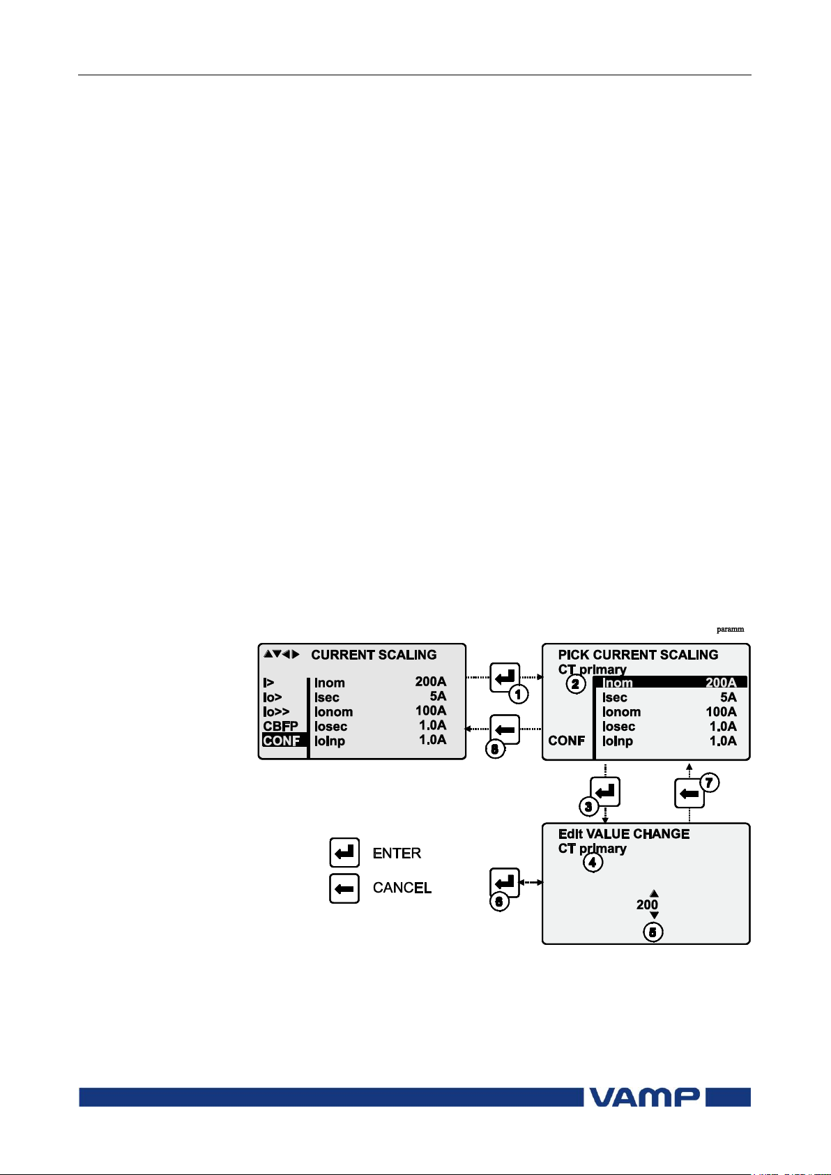
parameter change requires restarting, the display will show as
Figure 2.4-1.
Figure 2.4-1 Example of auto-reset display
Press CANCEL to return to the setting view. If a parameter
must be changed, press the ENTER key again. The parameter
can now be set. When the parameter change is confirmed with
the ENTER key, a [RESTART]- text appears to the top-right
corner of the display. This means that auto-resetting is
Page 27
Operation and configuration
2 Local panel user interface
2.4 Configuration and parameter
setting
VM59.EN001
VAMP 24h support phone +358 (0)20 753 3264
27
pending. If no key is pressed, the auto-reset will be executed
within few seconds.
2.4.1. Parameter setting
1. Move to the setting state of the desired menu (for example
CONF/CURRENT SCALING) by pushing the ENTER key.
The Pick text appears in the upper-left part of the display.
2. Enter the password associated with the configuration level
by pushing the INFO key and then using the arrow keys
and the ENTER key (default value is 0002). For more
information about the access levels, please refer to Chapter
2.2.4.
3. Scroll through the parameters using the UP and DOWN
keys. A parameter can be set if the background color of the
line is black. If the parameter cannot be set the parameter
is framed.
4. Select the desired parameter (for example Inom) with the
ENTER key.
5. Use the UP and DOWN keys to change a parameter value.
If the value contains more than one digit, use the LEFT and
RIGHT keys to shift from digit to digit, and the UP and
DOWN keys to change the digits.
6. Push the ENTER key to accept a new value. If you want to
leave the parameter value unchanged, exit the edit state by
pushing the CANCEL key.
Figure 2.4.1-1.Changing parameters
Page 28
2.4 Configuration and parameter
setting
2 Local panel user interface
Operation and configuration
28
VAMP 24h support phone +358 (0)20 753 3264
VM59.EN001
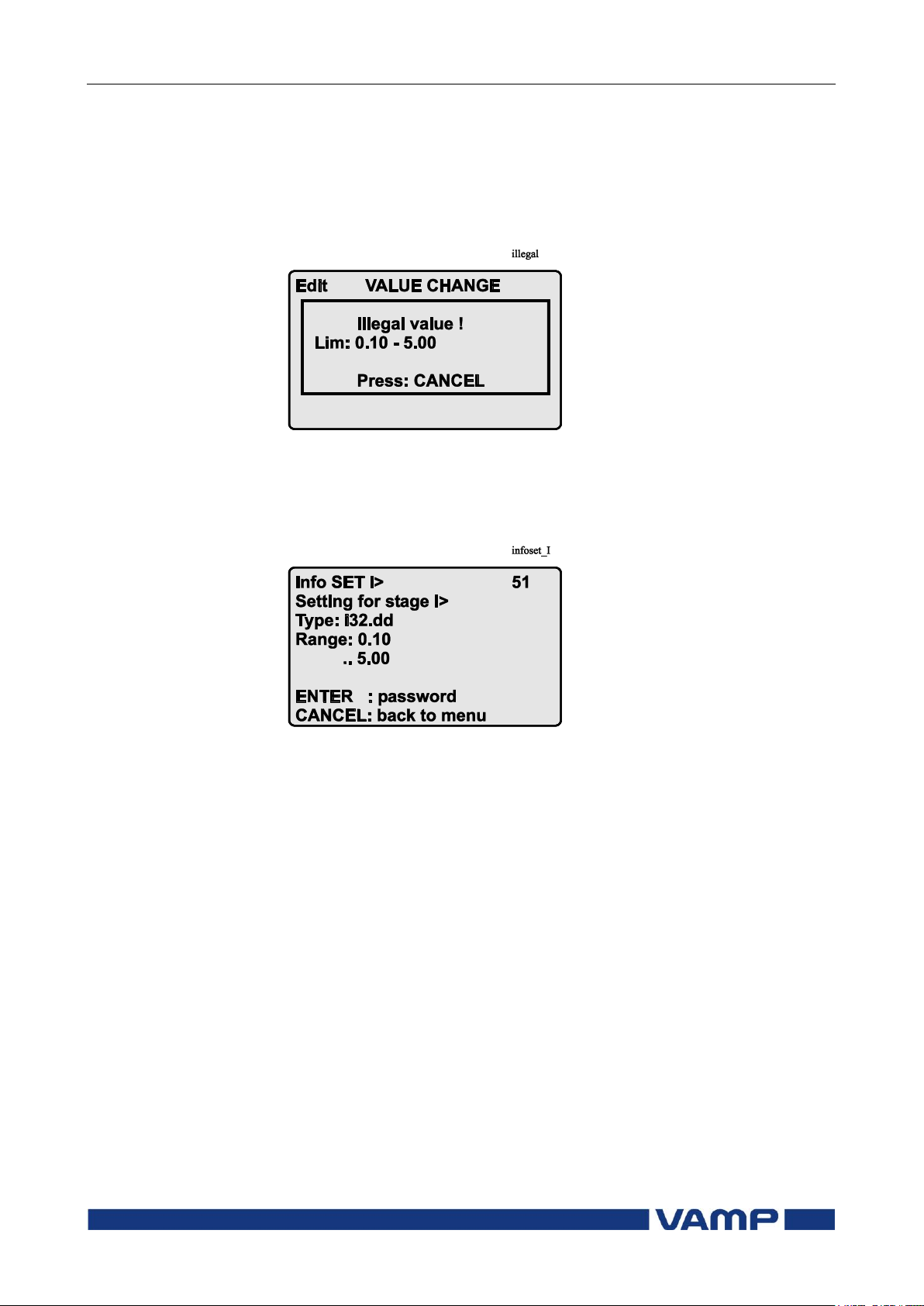
2.4.2. Setting range limits
If the given parameter setting values are out-of-range values, a
fault message will be shown when the setting is confirmed with
the ENTER key. Adjust the setting to be within the allowed
range.
Figure 2.4.2-1 Example of a fault message
The allowed setting range is shown in the display in the setting
mode. To view the range, push the INFO key. Push the
CANCEL key to return to the setting mode.
Figure 2.4.2-2 Allowed setting ranges show in the display
2.4.3. Disturbance recorder menu DR
Via the submenus of the disturbance recorder menu the
following functions and features can be read and set:
DISTURBANCE RECORDER
Recording mode (Mode)
Sample rate (SR)
Recording time (Time)
Pre trig time (PreTrig)
Manual trigger (ManTrig)
Count of ready records (ReadyRec)
REC. CHANNELS
Add a link to the recorder (AddCh)
Clear all links (ClrCh)
Page 29

Operation and configuration
2 Local panel user interface
2.4 Configuration and parameter
setting
VM59.EN001
VAMP 24h support phone +358 (0)20 753 3264
29
Available links:
DO, DI
IL
I2/In, I2/I1, I2, I1, IoCalc
f
Io
IoRMS
IL3, IL2, IL1
IL1Rem, IL2Rem, IL3Rem
THDIL1, THDIL2, THDIL3
IL1RMS, IL2RMS, IL3RMS
ILmin
ILmax
T
Uo
2.4.4. Configuring digital inputs DI
The following functions can be read and set via the submenus
of the digital inputs menu:
The status of digital inputs (DIGITAL INPUTS 1,2)
Operation counters (DI COUNTERS)
Operation delay (DELAYs for DigIn)
The polarity of the input signal (INPUT POLARITY). Either
normal open (NO) or normal closed (NC) circuit.
Event enabling EVENT MASK1
2.4.5. Configuring digital outputs DO
The following functions can be read and set via the submenus
of the digital outputs menu:
The status of the output relays (RELAY OUTPUTS1 and 2)
The forcing of the output relays (RELAY OUTPUTS1 and 2)
(only if Force = ON):
o Forced control (0 or 1) of the Trip relays
o Forced control (0 or 1) of the Alarm relays
o Forced control (0 or 1) of the IF relay
The configuration of the output signals to the output relays.
The configuration of the operation indicators (LED) Alarm
and Trip and application specific alarm leds A, B, C, D, E, F,
G and H (that is, the output relay matrix).
NOTE! The amount of Trip and Alarm relays depends on the relay
type and optional hardware.
Page 30

2.4 Configuration and parameter
setting
2 Local panel user interface
Operation and configuration
30
VAMP 24h support phone +358 (0)20 753 3264
VM59.EN001
2.4.6. Configuring analogue outputs AO (Option)
Via the submenus of the analogue output menu the following
functions can be read and set:
ANALOG OUTPUT
Value of AO1 (AO1)
Forced control of analogue output (Force)
ANALOG OUTPUT
Value linked to the analogue output (Lnk1)
(See list available links)
Scaled minimum of linked value (Min)
Scaled maximum of linked value (Max)
Scaled minimum of analogue output (AOmin)
Scaled maximum of analogue output (AOmax)
Value of analogue output (AO1)
Available links:
IL1, IL2, IL2
F
IL
Io, IoCalc
Uo
2.4.7. Protection menu Prot
The following functions can be read and set via the submenus
of the Prot menu:
Reset all the counters (PROTECTION SET/ClAll)
Read the status of all the protection functions (PROTECT
STATUS 1-x)
Enable and disable protection functions (ENABLED
STAGES 1-x)
Define the interlocking using block matrix (only with
VAMPSET).
Each stage of the protection functions can be disabled or
enabled individually in the Prot menu. When a stage is
enabled, it will be in operation immediately without a need to
reset the relay.
The relay includes several protection functions. However, the
processor capacity limits the number of protection functions
that can be active at the same time.
Page 31

Operation and configuration
2 Local panel user interface
2.4 Configuration and parameter
setting
VM59.EN001
VAMP 24h support phone +358 (0)20 753 3264
31
2.4.8. Configuration menu CONF
The following functions and features can be read and set via
the submenus of the configuration menu:
DEVICE SETUP
Bit rate for the command line interface in communication
ports and the USB-port in the front panel. The front panel
is always using this setting. If SPABUS is selected for the
rear panel port, the bit rate is according SPABUS settings.
Access level [Acc]
LANGUAGE
List of available languages in the relay
CURRENT SCALING
Rated phase CT primary current (Inom)
Rated phase CT secondary current (Isec)
Rated input of the relay [Iinput]is 5 A
Rated value of I
Rated value of I
Rated I
input of the relay [Ioinp] is 5 A / 1 A or 1 A / 0.2 A.
01
This is specified in the order code of the device.
The rated input values are usually equal to the rated secondary
value of the CT.
CT primary current (Ionom)
01
CT secondary current (Iosec)
01
The rated CT secondary may be greater than the rated input
but the continuous current must be less than four times the
rated input. In compensated, high impedance earthed and
isolated networks using cable transformer to measure residual
current I0, it is quite usual to use a relay with 1 A or 0.2 A
input although the CT is 5 A or 1A. This increases the
measurement accuracy.
The rated CT secondary may also be less than the rated input
but the measurement accuracy near zero current will decrease.
VOLTAGE SCALING
Rated Uo VT secondary voltage (Uosec)
DEVICE INFO
Relay type (Type VAMP 5X)
Serial number (SerN)
Software version (PrgVer)
Bootcode version (BootVer)
Page 32

2.4 Configuration and parameter
setting
2 Local panel user interface
Operation and configuration
32
VAMP 24h support phone +358 (0)20 753 3264
VM59.EN001
DATE/TIME SETUP
Day, month and year (Date)
Time of day (Time)
Date format (Style). The choices are "yyyy-mm-dd",
"dd.nn.yyyy" and "mm/dd/yyyy".
CLOCK SYNCHRONISATION
Digital input for minute sync pulse (SyncDI). If any digital
input is not used for synchronization, select "".
Daylight saving time for NTP synchronization (DST).
Detected source of synchronization (SyScr).
Synchronization message counter (MsgCnt).
Latest synchronization deviation (Dev).
The following parameters are visible only when the access level
is higher than "User".
Offset, i.e. constant error, of the synchronization source
(SyOS).
Auto adjust interval (AAIntv).
Average drift direction (AvDrft): "Lead" or "lag".
Average synchronization deviation (FilDev).
2.4.9. Protocol menu Bus
There are three optional communication ports in the rear
panel. The availability depends on the communication options
(see chapter Ordering code in the technical description). In
addition there is a USB-connector in the front panel overruling
the local port in the rear panel.
REMOTE PORT
Communication protocol for remote port [Protocol].
Message counter [Msg#]. This can be used to verify that the
device is receiving messages.
Communication error counter [Errors].
Communication time-out error counter [Tout].
Information of bit rate/data bits/parity/stop bits.
This value is not directly editable. Editing is done in the
appropriate protocol setting menus.
The counters are useful when testing the communication.
Page 33

Operation and configuration
2 Local panel user interface
2.4 Configuration and parameter
setting
VM59.EN001
VAMP 24h support phone +358 (0)20 753 3264
33
PC (LOCAL/SPA BUS)
This is a second menu for local port. The VAMPSET
communication status is showed.
Bytes/size of the transmitter buffer [Tx].
Message counter [Msg#]. This can be used to verify that the
device is receiving messages.
Communication error counter [Errors]
Communication time-out error counter [Tout].
Same information as in the previous menu.
EXTENSION PORT
Communication protocol for extension port [Protocol].
Message counter [Msg#]. This can be used to verify that the
device is receiving messages.
Communication error counter [Errors].
Communication time-out error counter [Tout].
Information of bit rate/data bits/parity/stop bits.
This value is not directly editable. Editing is done in the
appropriate protocol setting menus.
ETHERNET PORT
These parameters are used by the ethernet interface module.
For changing the nnn.nnn.nnn.nnn style parameter values,
VAMPSET is recommended.
Ethernet port protocol [Protoc].
IP Port for protocol [Port]
IP address [IpAddr].
Net mask [NetMsk].
Gateway [Gatew].
Name server [NameSw].
Network time protocol (NTP) server [NTPSvr].
TCP Keep alive interval [KeepAlive]
MAC address [MAC]
IP Port for Vampset [VS Port]
Message counter [Msg#]
Error counter [Errors]
Timeout counter [Tout]
MODBUS
Modbus address for this slave device [Addr]. This address
has to be unique within the system.
Modbus bit rate [bit/s]. Default is "9600".
Parity [Parity]. Default is "Even".
For details see the technical description part of the manual.
Page 34

2.4 Configuration and parameter
setting
2 Local panel user interface
Operation and configuration
34
VAMP 24h support phone +358 (0)20 753 3264
VM59.EN001
EXTERNAL I/O PROTOCOL
External I/O is actually a set of protocols which are designed to
be used with the extension I/O modules connected to the
extension port. Only one instance of this protocol is possible.
Selectable protocols:
Modbus: This is a modbus master protocol.
Bit rate [bit/s]. Default is ”9600”.
Parity [Parity]. Default is ”Even”.
RTDInput: This protocol is designed to be used together
with VIO 12A RTD input module.
Bit rate [bit/s]. Default is ”9600”.
Parity [Parity]. Default is ”Even”.
For details see the technical desctiption part of the manual.
DNP3
Only one instance of this protocol is possible.
Bit rate [bit/s]. Default is "9600".
[Parity].
Address for this device [SlvAddr]. This address has to be
unique within the system.
Master's address [MstrAddr].
For further details see the technical description part of the
manual.
IEC 60870-5-101
Bit rate [bit/s]. Default is “9600”.
[Parity].
Link layer address for this device [LLAddr].
ASDU address [ALAddr].
For further details see the technical description part of the
manual.
Page 35
Operation and configuration
2 Local panel user interface
2.4 Configuration and parameter
setting
VM59.EN001
VAMP 24h support phone +358 (0)20 753 3264
35
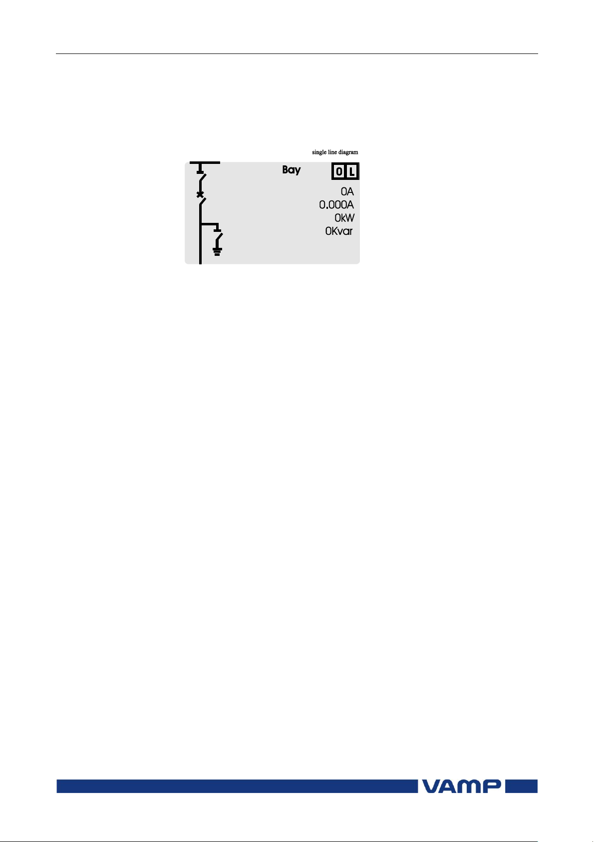
2.4.10. Single line diagram editing
The single-line diagram is drawn with the VAMPSET software.
For more information, please refer to the VAMPSET manual
(VMV.EN0xx).
Figure 2.4.10-1 Single line diagram
2.4.11. Blocking and interlocking configuration
The configuration of the blockings and interlocking is done with
the VAMPSET software. Any start - or trip signal can be used
for blocking the operation of any protection stage. Furthermore,
the interlocking between objects can be configured in the same
blocking matrix of the VAMPSET software. For more
information, please refer to the VAMPSET manual
(VMV.EN0xx).
Page 36

3 VAMPSET PC software
Operation and configuration
36
VAMP 24h support phone +358 (0)20 753 3264
VM59.EN001
3. VAMPSET PC software
The PC user interface can be used for:
On-site parameterization of the relay
Loading relay software from a computer
Reading measured values, registered values and events to a
computer.
Continuous monitoring of all values and events.
A USB port is available for connecting a local PC with
VAMPSET to the relay. A standard USB-B cable can be used.
The VAMPSET program can also use the TCP/IP LAN
connection. Optional hardware is required for Ethernet
connection.
There is a free of charge PC program called VAMPSET
available for configuration and setting of VAMP relays. Please
download the latest VAMPSET.exe from our web page
www.vamp.fi. For more information about the VAMPSET
software, please refer to the user’s manual with the code
VMV.EN0xx. Also the VAMPSET user’s manual is available at
our web site.
When the relay is connected to a PC with a USB, a virtual
comport will be created. The comport number may vary
depending on your computer hardware. In order to check the
correct port number, please go to Windows Device Manager:
Control Panel->System->Hardware->Device Manager and
under Ports(COM&LPT) for “USB Serial Port”. The correct
comport must be selected from the VAMPSET menu: Settings>Communication Settings. Speed setting can be set up to
187500 bps. Default setting in the relay is 38400 bps which can
be manually changed from the front panel of the device.
By default every new relay will create a new comport. To avoid
this behavior, the user needs to add a REG_BINARY value
called IgnoreHWSerNum04036001 to the Windows registry and
set it to 01. The location for this value is
HKEY_LOCAL_MACHINE\SYSTEM\CurrentControlSet\Con
trol\UsbFlags\.
Page 37

Technical description
Table of Contents
VM59.EN001
VAMP 24h support phone +358 (0)20 753 3264
37
Table of Contents
1. Introduction .......................................................................... 40
1.1. Main features ................................................................... 40
1.2. Principles of numerical protection techniques .......... 41
2. Protection functions ............................................................. 44
2.1. Maximum number of protection stages in one
application ................................................................................ 44
2.2. List of protection functions ............................................. 44
2.3. General features of protection stages ........................ 45
2.4. Relay function dependencies ...................................... 49
2.4.1. Current protection function dependencies ....... 49
2.5. Overcurrent protection I> (50/51) ................................ 49
2.5.1. Remote controlled overcurrent scaling .............. 54
2.6. Current unbalance stage I2> (46) ................................. 55
2.7. Directional earth fault protection I0φ> (67N) ............... 56
2.8. Earth fault protection I0> (50N/51N) ............................. 63
2.9. Zero sequence voltage protection U0> (59N) ............ 68
2.10. Thermal overload protection T> (49) ........................... 71
2.11. Circuit breaker failure stage CBFP (50BF) .................... 75
2.12. Line differential protection LdI> (87L) .......................... 76
2.12.1. Capacitive charging current ................................ 84
2.12.2. ANSI 85 (POC –signals) ........................................... 85
2.13. Programmable stages (99) ............................................ 86
2.14. Inverse time operation ................................................... 89
2.14.1. Standard inverse delays IEC, IEEE, IEEE2, RI ........ 91
2.14.2. Free parameterization using IEC, IEEE and IEEE2
equations ........................................................................... 102
2.14.3. Programmable inverse time curves ................... 103
3. Supporting functions .......................................................... 104
3.1. Event log ......................................................................... 104
3.2. Disturbance recorder ................................................... 106
3.3. Cold load pick-up and inrush current detection ..... 110
3.4. Current transformer supervision .................................. 113
3.5. Circuit breaker condition monitoring ......................... 114
3.6. System clock and synchronization ............................. 119
3.7. Running hour counter ................................................... 123
3.8. Timers ............................................................................... 124
3.9. Combined overcurrent status ..................................... 126
3.10. Self-supervision ............................................................... 129
3.10.1. Diagnostics ............................................................ 129
4. Measurement functions ..................................................... 131
4.1. Measurement accuracy .............................................. 131
4.2. RMS values ..................................................................... 132
4.3. Harmonics and Total Harmonic Distortion (THD) ...... 132
4.4. Demand values ............................................................. 133
4.5. Minimum and maximum values.................................. 133
Page 38

Table of Contents
Technical description
38
VAMP 24h support phone +358 (0)20 753 3264
VM59.EN001
4.6. Maximum values of the last 31 days and twelve
months ..................................................................................... 134
4.7. Voltage measurement modes .................................... 135
4.8. Symmetric components ............................................... 136
4.9. Primary, secondary and per unit scaling................... 137
4.9.1. Current scaling ...................................................... 137
4.9.2. Voltage scaling ..................................................... 139
4.10. Analogue output (option) ........................................... 140
4.10.1. mA scaling example ............................................ 140
5. Control functions ................................................................ 141
5.1. Output relays ................................................................. 141
5.2. Digital inputs ................................................................... 142
5.3. Virtual inputs and outputs ............................................ 144
5.4. Function keys / F1 & F2 ................................................. 145
5.5. Output matrix ................................................................. 145
5.6. Blocking matrix .............................................................. 146
5.7. Controllable objects ..................................................... 147
5.7.1. Local/Remote selection ...................................... 149
5.8. Auto-reclose function (79) ........................................... 150
5.9. Logic functions .............................................................. 157
6. Communication ................................................................. 158
6.1. Communication ports .................................................. 158
6.1.1. Local port (Front panel) ....................................... 158
6.1.2. Remote port .......................................................... 159
6.1.3. Extension port ........................................................ 159
6.1.4. Ethernet port .......................................................... 160
6.2. Communication protocols .......................................... 161
6.2.1. PC communication .............................................. 161
6.2.2. Modbus TCP and Modbus RTU ........................... 161
6.2.3. DNP 3.0 ................................................................... 162
6.2.4. External I/O (Modbus RTU master) ..................... 163
6.2.5. IEC 61850 ................................................................ 163
6.2.6. EtherNet/IP ............................................................. 165
7. Application ......................................................................... 167
7.1. Line protection and auto-reclosing ........................... 167
7.2. Trip circuit supervision ................................................... 168
7.2.1. Trip circuit supervision with one digital input .... 168
7.2.2. Trip circuit supervision with two digital inputs ... 173
8. Connections ....................................................................... 177
8.1. Rear panel view ............................................................ 177
8.2. Auxiliary voltage ............................................................ 178
8.3. Output relays ................................................................. 178
8.4. Serial communication connection............................. 179
8.4.1. Pin assignments of communication options ..... 179
8.4.2. Front panel connector ......................................... 180
8.5. Optional digital input / output card .......................... 180
8.6. External option modules .............................................. 183
Page 39

Technical description
Table of Contents
VM59.EN001
VAMP 24h support phone +358 (0)20 753 3264
39
8.6.1. External input / output module .......................... 183
8.7. Block diagrams .............................................................. 189
8.7.1. VAMP 59 ................................................................. 189
8.8. Connection examples .................................................. 190
8.8.1. VAMP 59 ................................................................. 190
9. Technical data ................................................................... 191
9.1. Connections................................................................... 191
9.1.1. Measuring circuitry ............................................... 191
9.1.2. Auxiliary voltage ................................................... 191
9.1.3. Digital inputs .......................................................... 192
9.1.4. Trip contacts .......................................................... 192
9.1.5. Alarm contacts ..................................................... 192
9.1.6. Local serial communication port ....................... 192
9.1.7. Remote control connection ............................... 193
9.1.8. Analogue output connection (option) ............. 193
9.2. Tests and environmental conditions .......................... 194
9.2.1. Disturbance tests .................................................. 194
9.2.2. Electrical safety tests ............................................ 195
9.2.3. Mechanical tests .................................................. 195
9.2.4. Environmental conditions .................................... 196
9.2.5. Casing .................................................................... 196
9.2.6. Package................................................................. 196
9.3. Protection stages .......................................................... 197
9.3.1. Differential protection .......................................... 197
9.3.2. Overcurrent protection........................................ 198
9.3.3. Circuit-breaker failure protection ...................... 201
9.3.4. Arc fault protection (option) .............................. 201
9.3.5. Digital input/output card (option) ..................... 202
9.4. Supporting functions ..................................................... 202
9.4.1. Disturbance recorder (DR) .................................. 202
9.4.2. Inrush current detection (68) .............................. 203
9.4.3. Transformer supervision ........................................ 203
10. Abbreviations and symbols .............................................. 204
11. Construction ....................................................................... 206
12. Order information ............................................................... 207
13. Revision history ................................................................... 209
14. Reference information ....................................................... 210
Page 40

1.1 Main features
1 Introduction
Technical description
40
VAMP 24h support phone +358 (0)20 753 3264
VM59.EN001
1. Introduction
This part of the user manual describes the protection functions,
provides a few application examples and contains technical
data.
The numerical VAMP device includes all the essential
overcurrent and earthfault protection functions needed.
Further, the device includes several programmable functions,
such as thermal, trip circuit supervision and circuit breaker
protection and communication protocols for various protection
and communication situations.
1.1. Main features
Fully digital signal handling with powerful microprocessor
technology, and high measuring accuracy on all the setting
ranges due to an accurate A/D conversion technique.
Complete set of functions for the proper protection of lines.
The device can be matched to the requirements of the
application by disabling the functions that are not needed.
Flexible control and blocking possibilities due to digital
signal control inputs (DI) and outputs (DO).
Easy adaptability of the device to various substations and
alarm systems due to flexible signal-grouping matrix in the
device.
Possibility to control objects (e.g. circuit-breakers,
disconnectors) from relay HMI or SCADA/automation
system
Freely configurable large display with six measurement
values.
Freely configurable interlocking schemes with basic logic
functions.
Recording of events and fault values into an event register
from which the data can be read via relay HMI or by means
of a PC based VAMPSET user interface.
All events, indications, parameters and waveforms are in
non-volatile memory.
Easy configuration, parameterisation and reading of
information via local HMI, or with a VAMPSET user
interface.
Easy connection to power plant automation system due to
several available communication protocols. Native
IEC61850 implementation is available as option.
Page 41

Technical description
1 Introduction
1.2 Principles of numerical
protection techniques
VM59.EN001
VAMP 24h support phone +358 (0)20 753 3264
41
Flexible communication option concept available to support
different media requirements (serial interfaces, optical
fibres, Ethernet etc),
Built-in, self-regulating ac/dc converter for auxiliary power
supply from any source within the range from 40 to 265 Vdc
or Vac. The alternative power supply is for 18 to 36 Vdc.
Built-in disturbance recorder for evaluating all the analogue
and digital signals.
1.2. Principles of numerical protection
techniques
The device is fully designed using numerical technology. This
means that all the signal filtering, protection and control
functions are implemented through digital processing.
The numerical technique used in the device is primarily based
on an adapted Fast Fourier Transformation (FFT). In FFT the
number of calculations (multiplications and additions), which
are required to filter out the measuring quantities, remains
reasonable.
By using synchronized sampling of the measured signal and a
sample rate according to the 2n series, the FFT technique leads
to a solution, which can be realized with just a 16 bit micro
controller, without using a separate DSP (Digital Signal
Processor).
The synchronized sampling means an even number of 2n
samples per period (e.g. 32 samples per a period). This means
that the frequency must be measured and the number of the
samples per period must be controlled accordingly so that the
number of the samples per period remains constant if the
frequency changes. Therefore, some current has to be injected
to the current input IL1 to adapt the network frequency for the
device. However, if this is not possible then the frequency must
be parameterised to the device.
Apart from the FFT calculations, some protection functions also
require the symmetrical components to be calculated for
obtaining the positive, negative and zero phase sequence
components of the measured quantity. For example, the
function of the current unbalanced stage is based on the use of
the negative phase sequence component of the current.
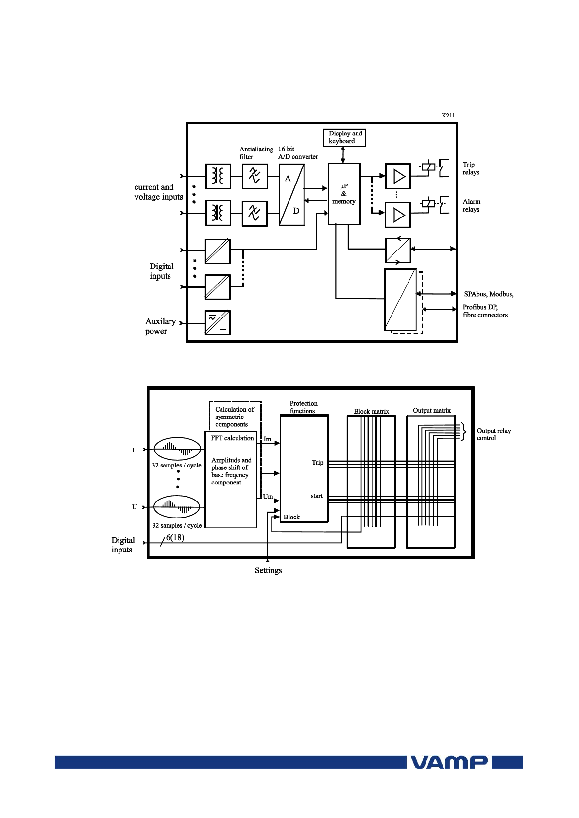
Figure 1-1 shows a principle block diagram of a numerical
device. The main components are the energizing inputs, digital
input elements, output relays, A/D converters and the micro
controller including memory circuits. Further, a device contains
a power supply unit and a human-machine interface (HMI).
Figure 1-2 shows the heart of the numerical technology. That is
the main block diagram for calculated functions.
Page 42
1.2 Principles of numerical
protection techniques
1 Introduction
Technical description
42
VAMP 24h support phone +358 (0)20 753 3264
VM59.EN001
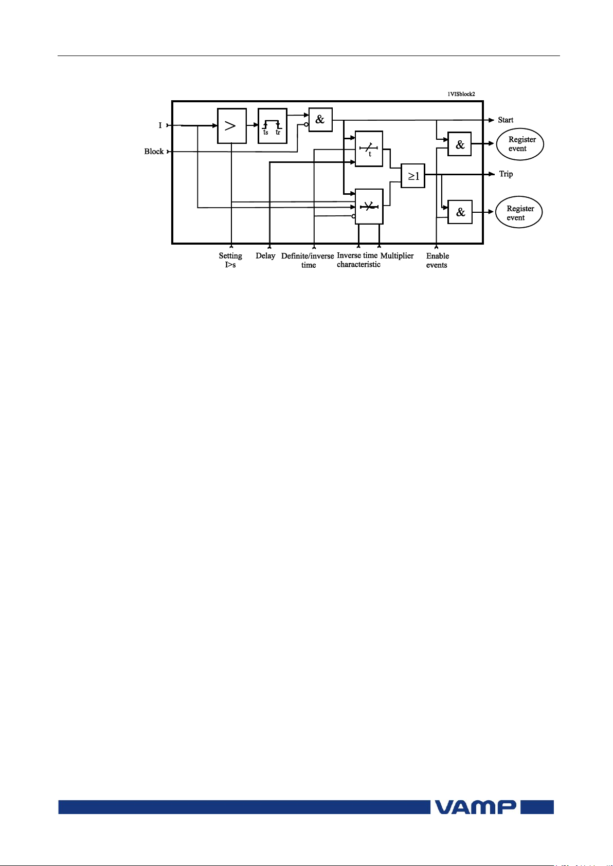
Figure 1-3 shows a principle diagram of a single-phase
overcurrent function.
Figure 1-1 Principle block diagram of the VAMP hardware
Figure 1-2 Block diagram of signal processing and protection software
Page 43
Technical description
1 Introduction
1.2 Principles of numerical
protection techniques
VM59.EN001
VAMP 24h support phone +358 (0)20 753 3264
43
Figure 1-3 Block diagram of a basic protection function
Page 44

2.1 Maximum number of
protection stages in one
application
2 Protection functions
Technical description
44
VAMP 24h support phone +358 (0)20 753 3264
VM59.EN001
IEEE/ANSI
code
IEC symbol
Function name
87L
LdI>,
LdI>>
Line differential protection
87Lf2
Second harmonic blocking
87Lf5
Fifth harmonic blocking
50/51
3I>, 3I>>,
3I>>>
Overcurrent protection
50N/51N
I0>, I0>>,
I0>>>,
I0>>>>
Earth fault protection
49
T>
Thermal overload protection
50BF
CBFP
Circuit-breaker failure protection
46
I2>
Current unbalance protection
59N
U0>, U0>>
Zero sequence voltage protection
67N,
50N/51N
Directional or non directional.
earth-fault, low-set stage,
sensitive, definite or inverse time
79
AR
Auto-reclosing
99
Prg1…8
Programmable stages
51F2
If2>
Second harmonic O/C stage
51F5
If5>
Fifth harmonic O/C stage
50ARC/
50NARC
ArcI>,
ArcI01>
Optional arc fault protection (with
an external module)
2. Protection functions
Each protection stage can independently be enabled or disabled
according to the requirements of the intended application.
2.1. Maximum number of protection
stages in one application
The device limits the maximum number of enabled stages to
about 30, depending on the type of the stages. For more
information, please see the configuration instructions in
chapter 2.4 of the Operation and Configuration instruction.
2.2. List of protection functions
Page 45

Technical description
2 Protection functions
2.3 General features of protection
stages
VM59.EN001
VAMP 24h support phone +358 (0)20 753 3264
45
Ok = „„
The stage is not detecting any fault.
Blocked
The stage is detecting a fault but blocked by
some reason.
Start
The stage is counting the operation delay.
Trip
The stage has tripped and the fault is still on.
2.3. General features of protection stages
Setting groups
Most stages have two setting groups. Changing between setting
groups can be controlled manually or using any of the digital
inputs, virtual inputs, virtual outputs or LED indicator signals.
By using virtual I/O the active setting group can be controlled
using the local panel display, any communication protocol or
using the inbuilt programmable logic functions.
Forcing start or trip condition for testing
The status of a protection stage can be one of the followings:
The blocking reason may be an active signal via the block
matrix from other stages, the programmable logic or any digital
input. Some stages also have inbuilt blocking logic. For more
details about block matrix, see chapter 5.6.
Forcing start or trip condition for testing purposes
There is a "Force flag" parameter which, when activated, allows
forcing the status of any protection stage to be "start" or "trip"
for a half second. By using this forcing feature any current
injection to the device is not necessary to check the output
matrix configuration, to check the wiring from the output
relays to the circuit breaker and also to check that
communication protocols are correctly transferring event
information to a SCADA system.
After testing the force flag will automatically reset 5-minute
after the last local panel push button activity.
The force flag also enables forcing of the output relays.
Start and trip signals
Every protection stage has two internal binary output signals:
start and trip. The start signal is issued when a fault has been
detected. The trip signal is issued after the configured
operation delay unless the fault disappears before the end of
the delay time.
Page 46
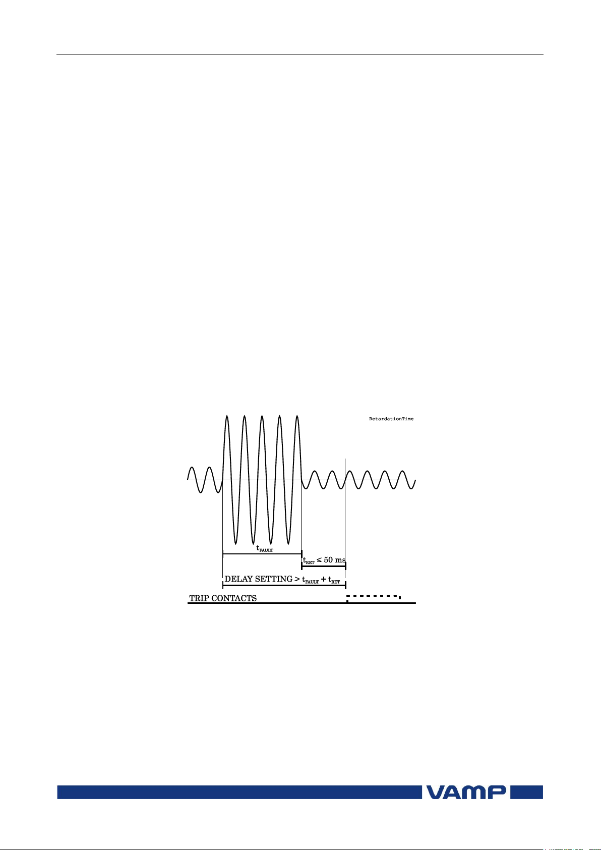
2.3 General features of
protection stages
2 Protection functions
Technical description
46
VAMP 24h support phone +358 (0)20 753 3264
VM59.EN001
Output matrix
Using the output matrix the user connects the internal start
and trip signals to the output relays and indicators. For more
details see chapter 5.4.
Blocking
Any protection function can be blocked with internal and
external signals using the block matrix (chapter 5.6). Internal
signals are for example logic outputs and start and trip signals
from other stages and external signals are for example digital
and virtual inputs.
When a protection stage is blocked, it won't pick-up in case of a
fault condition is detected. If blocking is activated during the
operation delay, the delay counting is frozen until the blocking
goes off or the pick-up reason, i.e. the fault condition,
disappears. If the stage is already tripping, the blocking has no
effect.
Retardation time
Retardation time is the time a protection relay needs to notice,
that a fault has been cleared during the operation time delay.
This parameter is important when grading the operation time
delay settings between relays.
Figure 2-1 Definition for retardation time. If the delay setting would be
slightly shorter, an unselective trip might occur (the dash line pulse).
For example when there is a big fault in an outgoing feeder, it
might start i.e. pick-up both the incoming and outgoing feeder
relay. However the fault must be cleared by the outgoing feeder
relay and the incoming feeder relay must not trip. Although the
operating delay setting of the incoming feeder is more than at
the outgoing feeder, the incoming feeder might still trip, if the
operation time difference is not big enough. The difference
must be more than the retardation time of the incoming feeder
Page 47
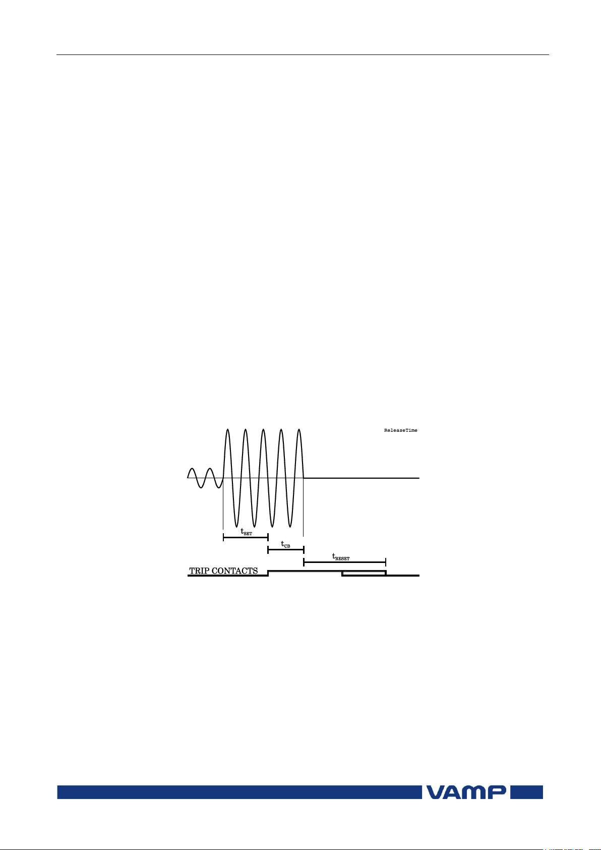
Technical description
2 Protection functions
2.3 General features of protection
stages
VM59.EN001
VAMP 24h support phone +358 (0)20 753 3264
47
relay plus the operating time of the outgoing feeder circuit
breaker.
Figure 2-1 shows an overcurrent fault seen by the incoming
feeder, when the outgoing feeder does clear the fault. If the
operation delay setting would be slightly shorter or if the fault
duration would be slightly longer than in the figure, an
unselective trip might happen (the dashed 40 ms pulse in the
figure). In VAMP devices the retardation time is less than 50
ms.
Reset time (release time)
Figure 2-2 shows an example of reset time i.e. release delay,
when the relay is clearing an overcurrent fault. When the
relay's trip contacts are closed the circuit breaker (CB) starts to
open. After the CB contacts are open the fault current will still
flow through an arc between the opened contacts. The current
is finally cut off when the arc extinguishes at the next zero
crossing of the current. This is the start moment of the reset
delay. After the reset delay the trip contacts and start contact
are opened. The reset time varies from fault to fault depending
on the fault size. After a big fault the time is longer. The reset
time also depends on the specific protection stage. The
maximum reset time for each stage is specified in chapter 9.2.
For most stages it is less than 95 ms.
Figure 2-2 Reset time is the time it takes the trip or start relay contacts to
open after the fault has been cleared.
Hysteresis or dead band
When comparing a measured value against a pick-up value,
some amount of hysteresis is needed to avoid oscillation near
equilibrium situation. With zero hysteresis any noise in the
measured signal or any noise in the measurement itself would
cause unwanted oscillation between fault-on and fault-off
situations.
Page 48
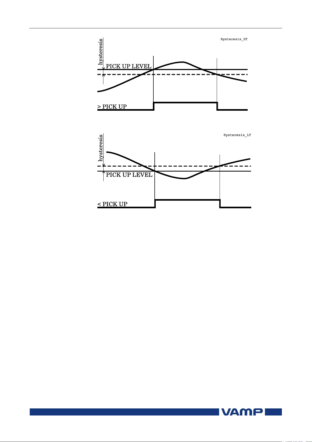
2.3 General features of
protection stages
2 Protection functions
Technical description
48
VAMP 24h support phone +358 (0)20 753 3264
VM59.EN001
Figure 2-3 Behaviour of a greater than comparator. For example in
overcurrent stages the hysteresis (dead band) acts according this figure.
Figure 2-4 Behaviour of a less than comparator. For example in
undercurrent stage the hysteresis (dead band) acts according this figure.
Page 49

Technical description
2 Protection functions
2.4 Relay function dependencies
VM59.EN001
VAMP 24h support phone +358 (0)20 753 3264
49
2.4. Relay function dependencies
2.4.1. Current protection function dependencies
The current based protection functions are relative to nominal
current, which is dependent of the application mode. In the
motor protection mode all of the current based functions are
relative to I
following exceptions.
I2> (46), I2>> (47), IST> (48), N> (66) are always dependent on
I
and they are only available when application mode is in
MOT
the motor protection.
and in the feeder protection mode to IN with
MOT
2.5. Overcurrent protection I> (50/51)
Overcurrent protection is used against short circuit faults and
heavy overloads.
The overcurrent function measures the fundamental frequency
component of the phase currents. The protection is sensitive for
the highest of the three phase currents. Whenever this value
exceeds the user's pick-up setting of a particular stage, this
stage picks up and a start signal is issued. If the fault situation
remains on longer than the user's operation delay setting, a
trip signal is issued.
Three independent stages
There are three separately adjustable overcurrent stages: I>,
I>> and I>>>. The first stage I> can be configured for definite
time (DT) or inverse time operation characteristic (IDMT). The
stages I>> and I>>> have definite time operation
characteristic. By using the definite delay type and setting the
delay to its minimum, an instantaneous (ANSI 50) operation is
obtained.
Figure 2-5 shows a functional block diagram of the I>
overcurrent stage with definite time and inverse time operation
time. Figure 2-6 shows a functional block diagram of the I>>
and I>>> overcurrent stages with definite time operation delay.
Inverse operation time
Inverse delay means that the operation time depends on the
amount the measured current exceeds the pick-up setting. The
bigger the fault current is the faster will be the operation.
Accomplished inverse delays are available for the I> stage. The
inverse delay types are described in chapter 2.14. The device
will show the currently used inverse delay curve graph on the
local panel display.
Page 50
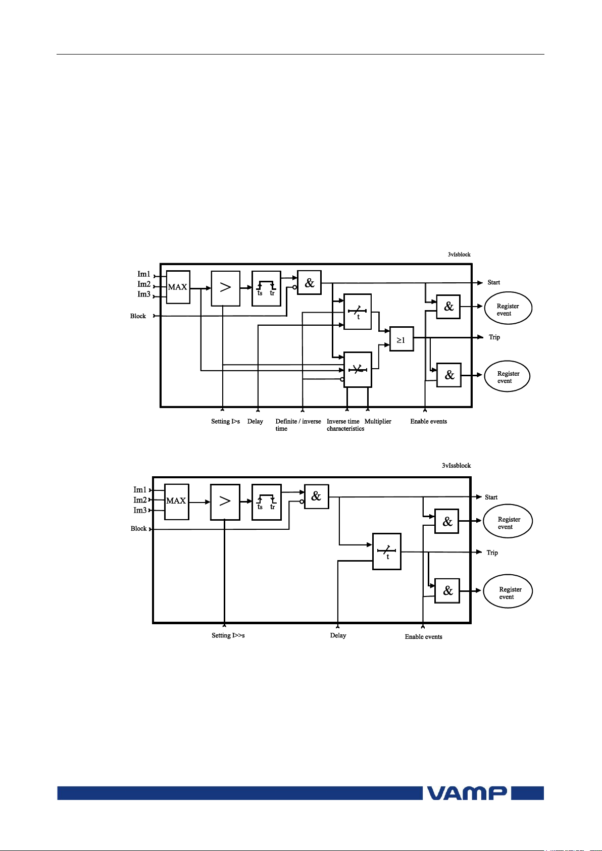
2.5 Overcurrent protection I>
(50/51)
2 Protection functions
Technical description
50
VAMP 24h support phone +358 (0)20 753 3264
VM59.EN001
Inverse time limitation
The maximum measured secondary current is 50xIN. This
limits the scope of inverse curves with high pick-up settings.
See chapter 2.14 for more information.
Cold load and inrush current handling
See chapter 3.3.
Setting groups
There are two settings groups available for each stage.
Switching between setting groups can be controlled by digital
inputs, virtual inputs (communication, logic) and manually.
Figure 2-5 Block diagram of the three-phase overcurrent stage I>.
Figure 2-6 Block diagram of the three-phase overcurrent stage I>> and
I>>>.
Page 51

Technical description
2 Protection functions
2.5 Overcurrent protection I>
(50/51)
VM59.EN001
VAMP 24h support phone +358 (0)20 753 3264
51
Parameter
Value
Unit
Description
Note
Status
Blocked
Start
Trip
Current status of the stage
F
F
TripTime
s Estimated time to trip
SCntr
Cumulative start counter
Clr
TCntr
Cumulative trip counter
Clr
SetGrp
1 or 2
Active setting group
Set
SGrpDI
-
DIx
VIx
LEDx
VOx
Fx
Digital signal to select the
active setting group
None
Digital input
Virtual input
LED indicator signal
Virtual output
Function key
Set
Force
Off
On
Force flag for status forcing for
test purposes. This is a
common flag for all stages and
output relays, too. This flag is
automatically reset 5 minutes
after the last front panel push
button pressing.
Set
ILmax A
The supervised value. Max. of
IL1, IL2 and IL3
Status
Start
Trip
Blocked
I> A
Pick-up value scaled to
primary value
I> xImode
Pick-up setting
Set
Curve
DT
IEC
IEEE
IEEE2
RI
PrgN
Delay curve family:
Definite time
Inverse time. See chapter 2.14.
Pre 1996
Set
Type
DT
NI
VI
EI
LTI
Para-
meters
Delay type.
Definite time
Inverse time. See chapter 2.14.
Set
Parameters of the overcurrent stage I> (50/51)
Page 52

2.5 Overcurrent protection I>
(50/51)
2 Protection functions
Technical description
52
VAMP 24h support phone +358 (0)20 753 3264
VM59.EN001
Parameter
Value
Unit
Description
Note
t> s
Definite operation time (for
definite time only)
Set
k>
Inverse delay multiplier (for
inverse time only)
Set
Dly20x
s Delay at 20xImode
Dly4x s
Delay at 4xImode
Dly2x s
Delay at 2xImode
Dly1x s
Delay at 1xImode
A, B, C, D,
E
User's constants for standard
equations. Type=Parameters.
See chapter 2.14.
Set
Parameter
Value
Unit
Description
Note
Status
Blocked
Start
Trip
Current status of the stage
F
F
SCntr
Cumulative start counter
C
TCntr
Cumulative trip counter
C
SetGrp
1 or 2
Active setting group
Set
SGrpDI
-
DIx
VIx
LEDx
VOx
Fx
Digital signal to select the
active setting group
None
Digital input
Virtual input
LED indicator signal
Virtual output
Function key
Set
Force
Off
On
Force flag for status forcing for
test purposes. This is a
common flag for all stages and
output relays, too.
Automatically reset by a 5minute timeout.
Set
ILmax A
The supervised value. Max. of
IL1, IL2 and IL3
I>>, I>>>
A Pick-up value scaled to
primary value
I>>, I>>>
xImode
Pick-up setting
Set
t>>, t>>>
s Definite operation time
Set
For details of setting ranges see chapter 9.2.
Set = An editable parameter (password needed)
C = Can be cleared to zero
F = Editable when force flag is on
Parameters of the overcurrent stages I>>, I>>> (50/51)
For details of setting ranges see chapter 9.2.
Set = An editable parameter (password needed)
C = Can be cleared to zero
F = Editable when force flag is on
Page 53

Technical description
2 Protection functions
2.5 Overcurrent protection I>
(50/51)
VM59.EN001
VAMP 24h support phone +358 (0)20 753 3264
53
Parameter
Value
Unit
Description
yyyy-mm-dd
Time stamp of the recording, date
hh:mm:ss.ms
Time stamp, time of day
Type
1-N
2-N
3-N
1-2
2-3
3-1
1-2-3
Fault type
Ground fault
Ground fault
Ground fault
Two phase fault
Two phase fault
Two phase fault
Three phase fault
Flt xImode
Maximum fault current
Load
xImode
1 s average phase currents before
the fault
EDly %
Elapsed time of the operating
time setting. 100% = trip
SetGrp
1 2
Active setting group during fault
Recorded values of the latest eight faults
There is detailed information available of the eight latest
faults: Time stamp, fault type, fault current, load current
before the fault, elapsed delay and setting group.
Recorded values of the overcurrent stages (8 latest faults)
I>, I>>, I>>> (50/51)
Page 54
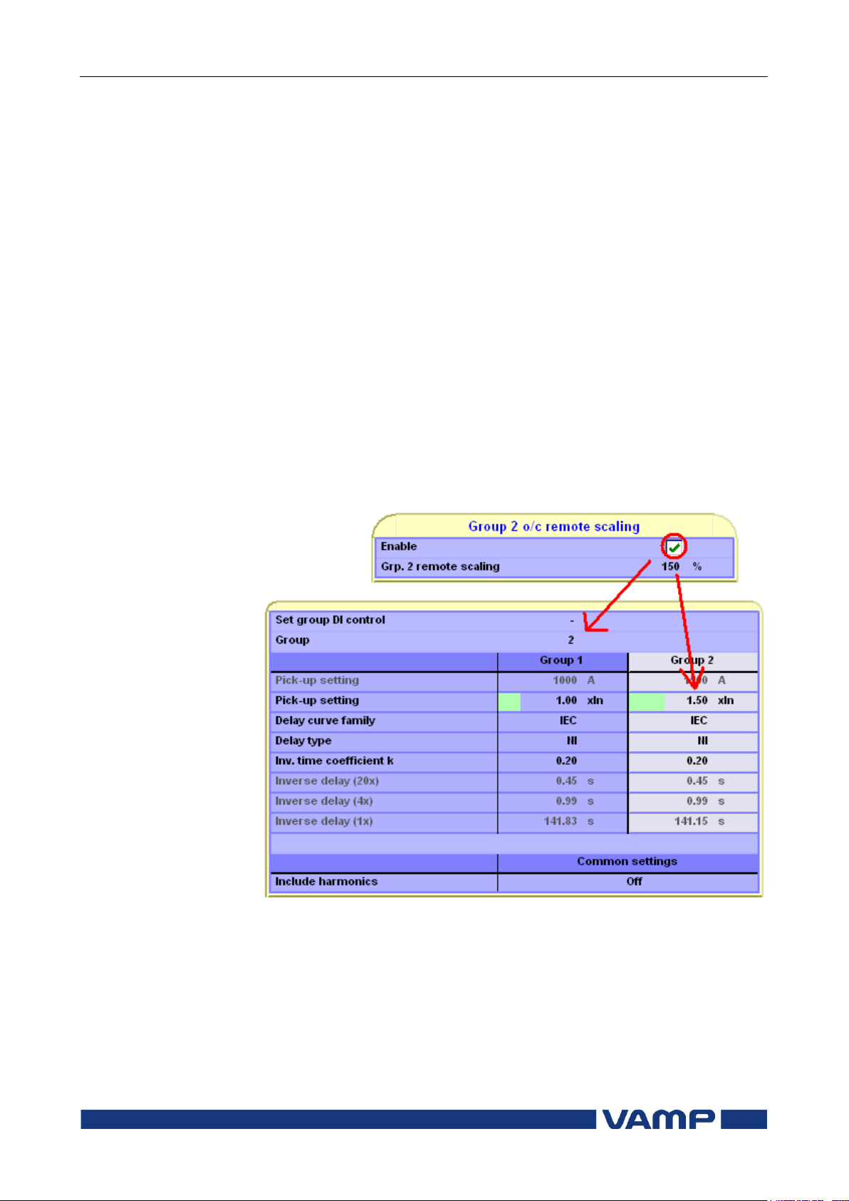
2.5 Overcurrent protection I>
(50/51)
2 Protection functions
Technical description
54
VAMP 24h support phone +358 (0)20 753 3264
VM59.EN001
2.5.1. Remote controlled overcurrent scaling
Pick-up setting of the three over current stages can also be
controlled remotely. In this case only two scaling coefficients
are possible: 100% (the scaling is inactive) and any configured
value between 10% - 200% (the scaling is active). When scaling
is enabled all settings of group one are copied to group two but
the pick-up value of group two is changed according the given
value (10-200%).
This feature can be enabled/disabled via VAMPSET or by
using the local panel. When using VAMPSET the scaling
can be activated and adjusted in the “protection stage
status 2” –menu. When using the local panel similar
settings can be found from the “prot” -menu.
It is also possible to change the scaling factor remotely by
using the modbus TCP –protocol. When changing the
scaling factor remotely value of 1% is equal to 1. Check the
correct modbus address for this application from the
vampset or from the communication parameter list.
Figure 2.5.1-1 Remote scaling example.
In the Figure 2.5.1-1 can be seen the affect of remote scaling.
After enabling group is changed from group one to group two
and all settings from group one are copied to group two. The
difference is that group two uses scaled pick-up settings.
NOTE! When remote scaling function is used it replaces all the
settings of group 2 so this function cannot be used simultaneously with normal group change.
Page 55

Technical description
2 Protection functions
2.6 Current unbalance stage I2>
(46)
VM59.EN001
VAMP 24h support phone +358 (0)20 753 3264
55
1
2
2
I
I
K
2
3
2
1
1201 ja
Parameter
Value
Unit
Default
Description
I2/I1>
2 … 70
%
20
Setting value, I2/I1
t>
1.0 … 600.0
s
10.0
Definite operating time
Type
DT
INV
-
DT
The selection of time
characteristics
S_On
Enabled;
Disabled
-
Enabled
Start on event
S_Off
Enabled;
Disabled
-
Enabled
Start off event
T_On
Enabled;
Disabled
-
Enabled
Trip on event
T_Off
Enabled;
Disabled
-
Enabled
Trip off event
Parameter
Value
Unit
Description
Measured
value
I2/I1 %
Relative negative sequence
component
Recorded
values
SCntr
Cumulative start counter
TCntr
Cumulative start counter
Flt %
Maximum I2/I1 fault component
EDly %
Elapsed time as compared to
the set operating time, 100% =
tripping
2.6. Current unbalance stage I
The purpose of the unbalance stage is to detect unbalanced load
conditions, for example a broken conductor of a heavy loaded
overhead line in case there is no earth fault.
The operation of the unbalanced load function is based on the
negative phase sequence component I2 related to the positive
phase sequence component I1. This is calculated from the phase
currents using the method of symmetrical components. The
function requires that the measuring inputs are connected
correctly so that the rotation direction of the phase currents are
as in chapter 8.8. The unbalance protection has definite time
operation characteristic.
, where
I1 = IL1 + aIL2 + a2IL3
I2 = IL1 + a2IL2 + aI
L3
, a phasor rotating constant
> (46)
2
Setting parameters of the current unbalanced stageI2> (46)
in feeder mode:
Measured and recorded values of of the current unbalanced
stageI2> (46) in feeder mode:
Page 56

2.7 Directional earth fault
protection I0φ> (67N)
2 Protection functions
Technical description
56
VAMP 24h support phone +358 (0)20 753 3264
VM59.EN001
2.7. Directional earth fault protection I
(67N)
The directional earth fault protection is used for earth faults in
networks where a selective and sensitive earth fault protection
is needed and in applications with varying network structure
and length.
The device consists of versatile protection functions for earth
fault protection in various network types.
The function is sensitive to the fundamental frequency
component of the residual current and zero sequence voltage
and the phase angle between them. The attenuation of the
third harmonic is more than 60 dB. Whenever the size of I0 and
U0 and the phase angle between I0 and U0 fulfils the pick-up
criteria, the stage picks up and a start signal is issued. If the
fault situation remains on longer than the user's operation time
delay setting, a trip signal is issued.
Polarization
Zero sequence voltageU0 is used for polarization i.e. the angle
reference for I0. The U0 voltage is measured via energizing
input U0:
0φ
>
3LN+U
: The zero sequence voltage is measured with
0
voltage transformer(s) for example using a broken delta
connection. The setting values are relative to the VT0
secondary voltage defined in configuration.
NOTE! The U0 signal must be connected according the connection diagram
(Figure 8.8.1-1) in order to get a correct polarization.
Page 57

Technical description
2 Protection functions
2.7 Directional earth fault
protection I0φ> (67N)
VM59.EN001
VAMP 24h support phone +358 (0)20 753 3264
57
Modes for different network types
The available modes are:
ResCap
This mode consists of two sub modes, Res and Cap. A digital
signal can be used to dynamically switch between these two
sub modes. This feature can be used with compensated
networks, when the Petersen coil is temporarily switched
off.
o Res
The stage is sensitive to the resistive component of
the selected I0 signal. This mode is used with
compensated networks (resonant grounding) and
networks earthed with a high resistance.
Compensation is usually done with a Petersen coil
between the neutral point of the main transformer
and earth. In this context "high resistance" means,
that the fault current is limited to be less than the
rated phase current. The trip area is a half plane as
drawn in Figure 2.7-2. The base angle is usually set
to zero degrees.
o Cap
The stage is sensitive to the capacitive component of
the selected I0 signal. This mode is used with
unearthed networks. The trip area is a half plane as
drawn in Figure 2.7-2. The base angle is usually set
to zero degrees.
Sector
This mode is used with networks earthed with a small
resistance. In this context "small" means, that a fault
current may be more than the rated phase currents. The
trip area has a shape of a sector as drawn in Figure 2.7-3.
The base angle is usually set to zero degrees or slightly on
the lagging inductive side (i.e. negative angle).
Undir
This mode makes the stage equal to the undirectional stage
I0>. The phase angle and U0 amplitude setting are
discarded. Only the amplitude of the selected I0 input is
supervised.
Input signal selection
Each stage can be connected to supervise any of the following
inputs and signals:
Input I
Calculated signal I
earthed networks. I
for all networks other than rigidly earthed.
01
for rigidly and low impedance
0Calc
= IL1 + IL2 + IL3 = 3I0.
0Calc
Page 58

2.7 Directional earth fault
protection I0φ> (67N)
2 Protection functions
Technical description
58
VAMP 24h support phone +358 (0)20 753 3264
VM59.EN001
Additionally the stage I0> has one more input signal
alternative to measure current peaks to detect short restriking
intermittent earth faults:
I
to measure the peak value of input I01.
01Peak
Intermittent earth fault detection
Short earth faults make the protection to start (to pick up), but
will not cause trip. When starting happens often enough, such
intermittent faults can be cleared using the intermittent time
setting. The mode should be Undir. The phase angle detection
of I0 in directional mode is insecure.
When a new start happens within the set intermittent time,
the operation delay counter is not cleared between adjacent
faults and finally the stage will trip. By using input signal
I
a single one-millisecond current peak is enough to start
01Peak
the stage and increase the delay counter by 20 ms. For example
if the operating time is 120 ms, and the time between two
peaks does not exceed the intermittent time setting, the sixth
peak will cause a trip.
Two independent stages
There are two separately adjustable stages: I0> and I0>>.
Both the stages can be configured for definite time delay (DT)
or inverse time delay operation time.
Inverse operation time
Inverse delay means that the operation time depends on the
amount the measured current exceeds the pick-up setting. The
bigger the fault current is the faster will be the operation.
Accomplished inverse delays are available for both stages I0>
and I0>>. The inverse delay types are described in chapter
2.14. The device will show a scaleable graph of the configured
delay on the local panel display.
Inverse time limitation
The maximum measured secondary residual current is 10xI0N
and maximum measured phase current is 50xIN. This limits the
scope of inverse curves with high pick-up settings. See chapter
2.14 for more information.
Page 59
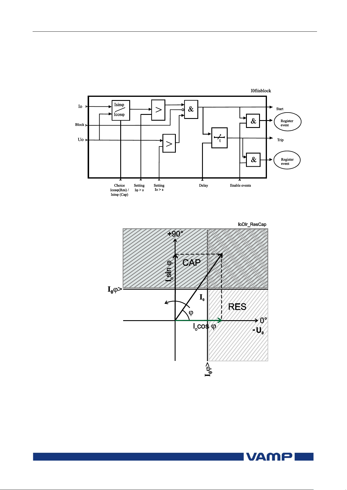
Technical description
2 Protection functions
2.7 Directional earth fault
protection I0φ> (67N)
VM59.EN001
VAMP 24h support phone +358 (0)20 753 3264
59
Setting groups
There are two settings groups available for each stage.
Switching between setting groups can be controlled by digital
inputs, virtual inputs (mimic display, communication, logic)
and manually.
Figure 2.7-1. Block diagram of the directional earth fault stages I0> and
I0>>
Figure 2.7-2. Operation characteristic of the directional earth fault
protection in Res or Cap mode. Res mode can be used with compensated
networks and Cap mode is used with ungrounded networks.
Page 60
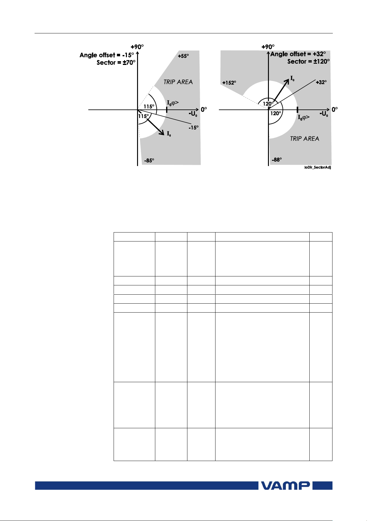
2.7 Directional earth fault
protection I0φ> (67N)
2 Protection functions
Technical description
60
VAMP 24h support phone +358 (0)20 753 3264
VM59.EN001
Parameter
Value
Unit
Description
Note
Status
Blocked
Start
Trip
Current status of the stage
F
F
TripTime
s Estimated time to trip
SCntr
Cumulative start counter
Clr
TCntr
Cumulative trip counter
Clr
SetGrp
1 or 2
Active setting group
Set
SGrpDI
-
DIx
VIx
LEDx
VOx
Fx
Digital signal to select the
active setting group
None
Digital input
Virtual input
LED indicator signal
Virtual output
Function key
Set
Force
Off
On
Force flag for status forcing
for test purposes. This is a
common flag for all stages and
output relays, too.
Automatically reset by a 5minute timeout.
Set
Io
IoCalc
IoPeak
pu
The supervised value
according the parameter
"Input" below.
(I0> only)
Figure 2.7-3. Two example of operation characteristics of the directional
earth fault stages in sector mode. The drawn I0 phasor in both figures is
inside the trip area. The angle offset and half sector size are user‟s
parameters.
Parameters of the directional earth fault stages
I0>, I0>> (67N)
Page 61

Technical description
2 Protection functions
2.7 Directional earth fault
protection I0φ> (67N)
VM59.EN001
VAMP 24h support phone +358 (0)20 753 3264
61
Parameter
Value
Unit
Description
Note
IoRes pu
Resistive part of I0 (only when
"InUse"=Res)
IoCap pu
Capacitive part of I0 (only
when "InUse"=Cap)
Io>
A Pick-up value scaled to
primary value
Io>
pu
Pick-up setting relative to the
parameter “Input” and the
corresponding CT value
Set
Uo> %
Pick-up setting for U0
Set
Uo %
Measured U0
Curve
DT
IEC
IEEE
IEEE2
RI
PrgN
Delay curve family:
Definite time
Inverse time. See chapter
2.14.
Set
Type
DT
NI
VI
EI
LTI
Paramet
ers
Delay type.
Definite time
Inverse time. See chapter
2.14.
Set
t> s
Definite operation time (for
definite time only)
Set
k>
Inverse delay multiplier (for
inverse time only)
Set
Mode
ResCap
Sector
Undir
High impedance earthed nets
Low impedance earthed nets
Undirectional mode
Set
Offset
Angle offset (MTA) for RecCap
and Sector modes
Set
Sector
Default
= 88
±°
Half sector size of the trip
area on both sides of the offset
angle
Set
ChCtrl
Res
Cap
DI1, DI2
VI1..4
Res/Cap control in mode
ResCap
Fixed to Resistive
characteristic
Fixed to Capacitive
characteristic
Controlled by digital input
Controlled by virtual input
Set
Page 62
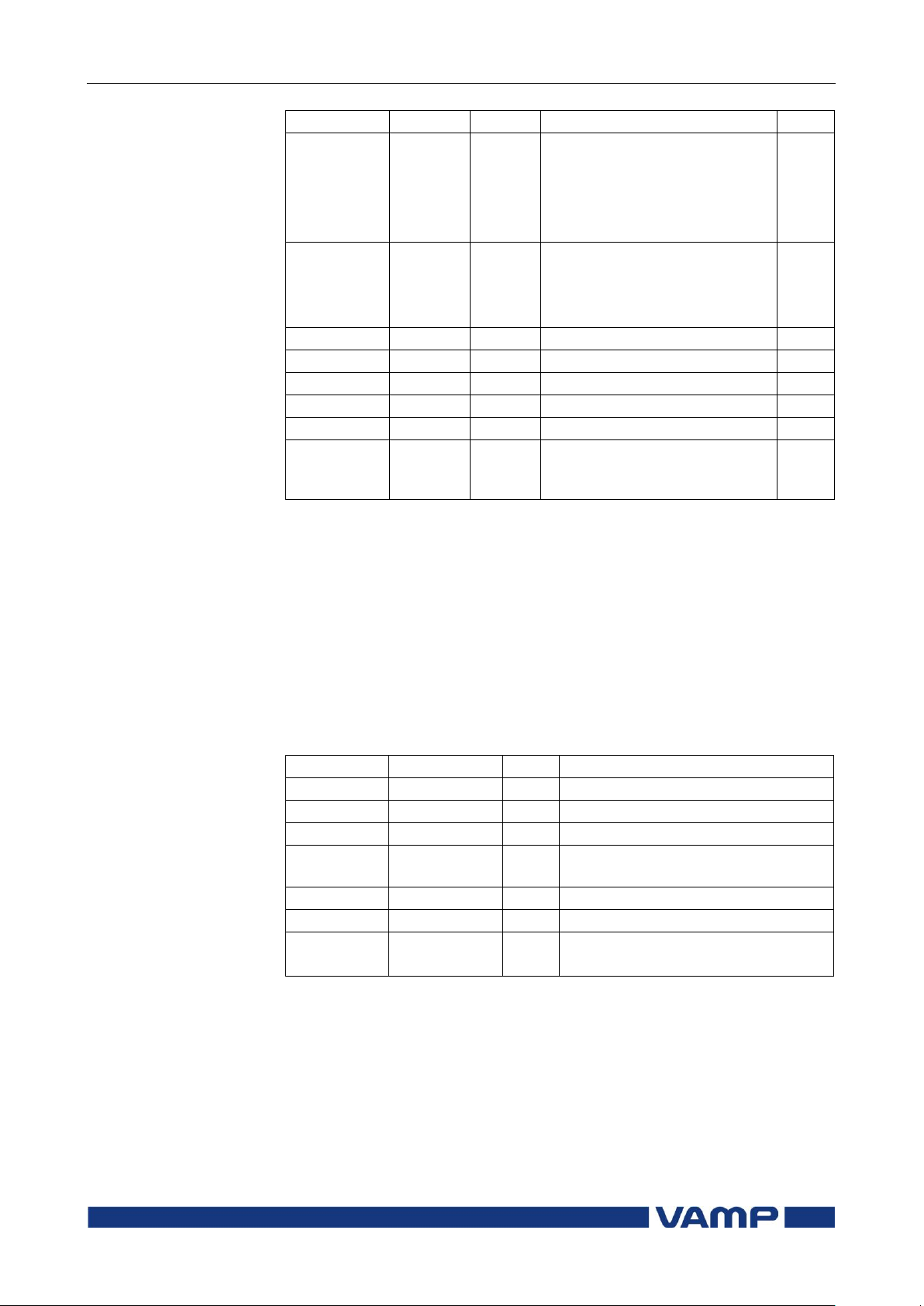
2.7 Directional earth fault
protection I0φ> (67N)
2 Protection functions
Technical description
62
VAMP 24h support phone +358 (0)20 753 3264
VM59.EN001
Parameter
Value
Unit
Description
Note
InUse
Res
Cap
Selected submode in mode
ResCap.
Mode is not ResCap
Submode = resistive
Submode = capacitive
Input
Io1
IoCalc
Io1Peak
X1-7,8,9. See chapter 8.
IL1 + IL2 + IL3
X1-7,8,9 peak mode (I0>
only)
Set
Intrmt s
Intermittent time
Set
Dly20x
s Delay at 20xIon
Dly4x s
Delay at 4xIon
Dly2x s
Delay at 2xIon
Dly1x s
Delay at 1xIon
A, B, C, D,
E
User's constants for standard
equations. Type=Parameters.
See chapter 2.14.
Set
Parameter
Value
Unit
Description
yyyy-mm-dd
Time stamp of the recording, date
hh:mm:ss.ms
Time stamp, time of day
Flt pu
Maximum earth fault current
EDly %
Elapsed time of the operating time
setting. 100% = trip
Angle
Fault angle of I0. U0 = 0
Uo %
Max. U0 voltage during the fault
SetGrp
1
2
Active setting group during fault
For details of setting ranges see chapter 9.2.
Set = An editable parameter (password needed)
C = Can be cleared to zero
F = Editable when force flag is on
Recorded values of the latest eight faults
There is detailed information available of the eight latest earth
faults: Time stamp, fault current, elapsed delay and setting
group.
Recorded values of the directional earth fault stages (8 latest
faults) I0>, I0>> (67N)
Page 63
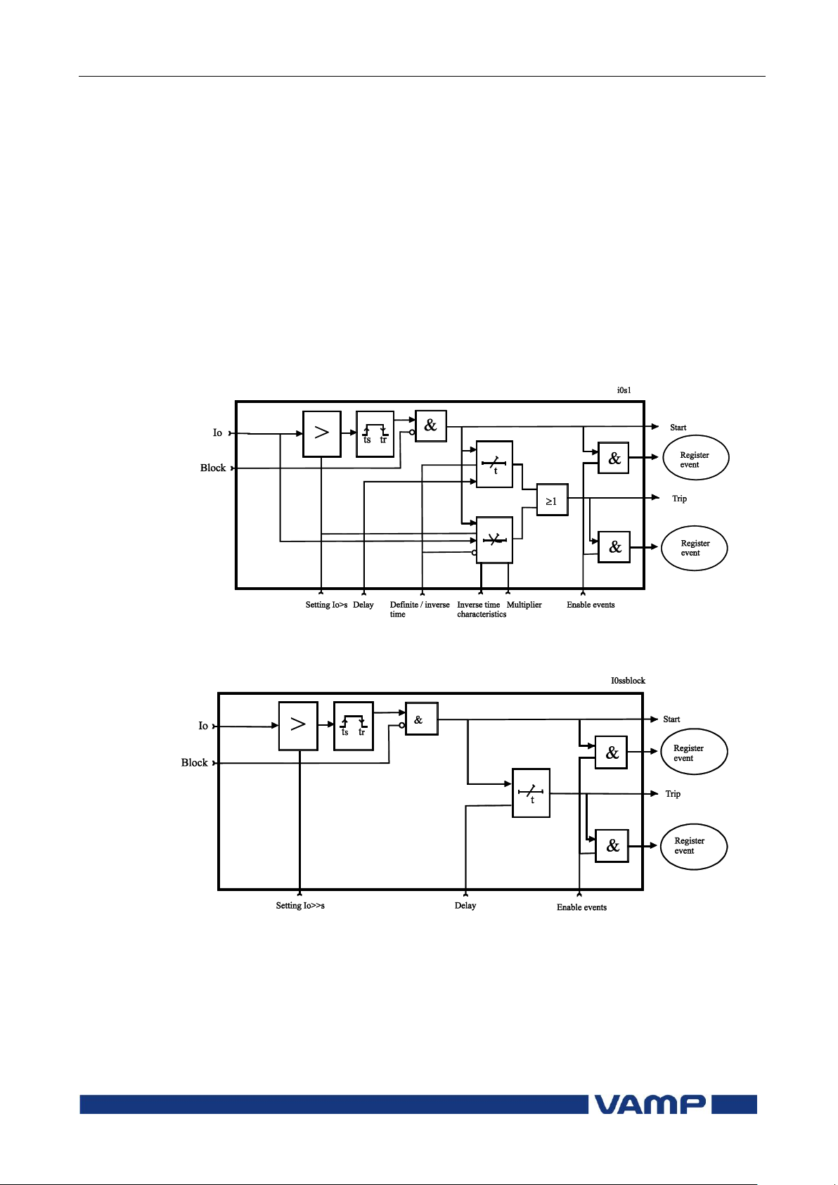
Technical description
2 Protection functions
2.8 Earth fault protection I0>
(50N/51N)
VM59.EN001
VAMP 24h support phone +358 (0)20 753 3264
63
2.8. Earth fault protection I
The undirectional earth fault protection is to detect earth faults
in low impedance earthed networks. In high impedance earthed
networks, compensated networks and isolated networks
undirectional earth fault can be used as back-up protection.
The undirectional earth fault function is sensitive to the
fundamental frequency component of the residual current 3I0.
The attenuation of the third harmonic is more than 60 dB.
Whenever this fundamental value exceeds the user's pick-up
setting of a particular stage, this stage picks up and a start
signal is issued. If the fault situation remains on longer than
the user's operation time delay setting, a trip signal is issued.
> (50N/51N)
0
Figure 2-7 Block diagram of the earth fault stage I0>
Figure 2-8 Block diagram of the earth fault stages I0>>, I0>>> and I0>>>>
Figure 2-7 shows a functional block diagram of the I0> earth
overcurrent stage with definite time and inverse time operation
time. Figure 2-8 shows a functional block diagram of the I0>>,
I0>>> and I0>>>> earth fault stages with definite time
operation delay.
Page 64

2.8 Earth fault protection I0>
(50N/51N)
2 Protection functions
Technical description
64
VAMP 24h support phone +358 (0)20 753 3264
VM59.EN001
Input signal selection
Each stage can be connected to supervise any of the following
inputs and signals:
Input I
Calculated signal I
earthed networks. I
for all networks other than rigidly earthed.
01
for rigidly and low impedance
0Calc
0Calc
= I
L1
+ I
+ IL3.
L2
Additionally the stage I0> has one more input signal
alternative to measure current peaks to detect a restriking
intermittent earth fault:
I
to measure the peak value of input I01.
01Peak
Intermittent earth fault detection
Short earth faults make the protection to start (pick up), but
will not cause trip. When starting happens often enough, such
intermittent faults can be cleared using the intermittent time
setting.
When a new start happens within the set intermittent time,
the operation delay counter is not cleared between adjacent
faults and finally the stage will trip. By using input signal
I
a single one-millisecond current peak is enough to start
01Peak
the stage and increase the delay counter by 20 ms. For example
if the operating time is 120 ms, and the time between two
peaks does not exceed the intermittent time setting, the sixth
peak will cause a trip.
Four or six independent undirectional earth fault overcurrent stages
There are four separately adjustable earth fault stages: I0>,
I0>>, I0>>>, and I0>>>>. The first stage I0> can be configured
for definite time (DT) or inverse time operation characteristic
(IDMT). The other stages have definite time operation
characteristic. By using the definite delay type and setting the
delay to its minimum, an instantaneous (ANSI 50N) operation
is obtained.
Inverse operation time (I0> stage only)
Inverse delay means that the operation time depends on the
amount the measured current exceeds the pick-up setting. The
bigger the fault current is the faster will be the operation.
Accomplished inverse delays are available for the I0> stage.
The inverse delay types are described in chapter 2.14. The
device will show a scaleable graph of the configured delay on
the local panel display.
Page 65

Technical description
2 Protection functions
2.8 Earth fault protection I0>
(50N/51N)
VM59.EN001
VAMP 24h support phone +358 (0)20 753 3264
65
Parameter
Value
Unit
Description
Note
Status
Blocked
Start
Trip
Current status of the stage
F
F
TripTime
s Estimated time to trip
SCntr
Cumulative start counter
Clr
TCntr
Cumulative trip counter
Clr
SetGrp
1 or 2
Active setting group
Set
SGrpDI
-
DIx
VIx
LEDx
VOx
Fx
Digital signal to select the
active setting group
None
Digital input
Virtual input
LED indicator signal
Virtual output
Function key
Set
Force
Off
On
Force flag for status forcing
for test purposes. This is a
common flag for all stages
and output relays, too.
Automatically reset by a 5minute timeout.
Set
Io
IoCalc
IoPeak
pu
The supervised value
according the parameter
"Input" below.
Io> A
Pick-up value scaled to
primary value
Io> pu
Pick-up setting relative to
the parameter "Input" and
the corresponding CT value
Set
Inverse time limitation
The maximum measured secondary residual current is 10xI0N
and maximum measured phase current is 50xIN. This limits the
scope of inverse curves with high pick-up settings. See chapter
2.14 for more information.
Setting groups
There are two settings groups available for each stage.
Switching between setting groups can be controlled by digital
inputs, virtual inputs (communication, logic) and manually.
Parameters of the undirectional earth fault stage
I0> (50N/51N)
Page 66

2.8 Earth fault protection I0>
(50N/51N)
2 Protection functions
Technical description
66
VAMP 24h support phone +358 (0)20 753 3264
VM59.EN001
Parameter
Value
Unit
Description
Note
Curve
DT
IEC
IEEE
IEEE2
RI
PrgN
Delay curve family:
Definite time
Inverse time. See chapter
2.14.
Set
Type
DT
NI
VI
EI
LTI
Parameters
Delay type.
Definite time
Inverse time. See chapter
2.14.
Set
t> s
Definite operation time (for
definite time only)
Set
k>
Inverse delay multiplier (for
inverse time only)
Set
Input
Io1
IoCalc
Io1Peak
X1-7,8,9. See chapter 8.
IL1 + IL2 + IL3
X1-7,8,9. peak mode
Set
Intrmt
s Intermittent time
Set
Dly20x
s Delay at 20xIon
Dly4x
s Delay at 4xIon
Dly2x
s Delay at 2xIon
Dly1x
s Delay at 1xIon
A, B, C, D,
E
User‟s constants for standard
equations. Type=Parameters.
See chapter 2.14.
Set
For details of setting ranges see chapter 9.2.
Set = An editable parameter (password needed)
C = Can be cleared to zero
F = Editable when force flag is on
Page 67

Technical description
2 Protection functions
2.8 Earth fault protection I0>
(50N/51N)
VM59.EN001
VAMP 24h support phone +358 (0)20 753 3264
67
Parameter
Value
Unit
Description
Note
Status
Blocked
Start
Trip
Current status of the stage
F
F
TripTime
s Estimated time to trip
SCntr
Cumulative start counter
Clr
TCntr
Cumulative trip counter
Clr
SetGrp
1 or 2
Active setting group
Set
SgrpDI
-
Dix
Vix
LEDx
VOx
Fx
Digital signal to select the
active setting group
None
Digital input
Virtual input
LED indicator signal
Virtual output
Function key
Set
Force
Off
On
Force flag for status forcing
for test purposes. This is a
common flag for all stages and
output relays, too.
Automatically reset by a 5minute timeout.
Set
Io
IoCalc
pu
The supervised value
according the parameter
“Input” below.
Io>>
Io>>>
Io>>>>
A Pick-up value scaled to
primary value
Io>>
Io>>>
Io>>>>
pu
Pick-up setting relative to the
parameter "Input" and the
corresponding CT value
Set
t> s
Definite operation time (for
definite time only)
Set
Input
Io1
IoCalc
X1-7,8,9. See chapter 8.
IL1 + IL2 + IL3
Set
Parameters of the undirectional earth fault stages
I0>>, I0>>>, I0>>>> (50N/51N)
For details of setting ranges see chapter 9.2.
Set = An editable parameter (password needed)
C = Can be cleared to zero
F = Editable when force flag is on
Recorded values of the latest eight faults
There is detailed information available of the eight latest earth
faults: Time stamp, fault current, elapsed delay and setting
group.
Page 68

2.9 Zero sequence voltage
protection U0> (59N)
2 Protection functions
Technical description
68
VAMP 24h support phone +358 (0)20 753 3264
VM59.EN001
Parameter
Value
Unit
Description
yyyy-mm-dd
Time stamp of the recording, date
hh:mm:ss.ms
Time stamp, time of day
Flt pu
Maximum earth fault current
EDly %
Elapsed time of the operating time
setting. 100% = trip
SetGrp
1
2
Active setting group during fault
Recorded values of the undirectional earth fault stages (8
latest faults) I0>, I0>>, I0>>>, I0>>>> (50N/51N)
2.9. Zero sequence voltage protection U
(59N)
The zero sequence voltage protection is used as unselective
backup for earth faults and also for selective earth fault
protections for motors having a unit transformer between the
motor and the busbar.
This function is sensitive to the fundamental frequency
component of the zero sequence voltage. The attenuation of the
third harmonic is more than 60 dB. This is essential, because
3n harmonics exist between the neutral point and earth also
when there is no earth fault.
Whenever the measured value exceeds the user's pick-up
setting of a particular stage, this stage picks up and a start
signal is issued. If the fault situation remains on longer than
the user's operation time delay setting, a trip signal is issued.
Measuring the zero sequence voltage
The zero sequence voltage is measured with three voltage
transformers, e.g. broken delta connection (see chapter 4.7):
0
>
U
: The zero sequence voltage is measured with voltage
0
transformers for example using a broken delta connection.
The setting values are relative to the VT0 secondary voltage
defined in configuration.
NOTE! The U0 signal must be connected according the connection diagram
(Figure 8.8.1-1) in order to get a correct polarization
Two independent stages
There are two separately adjustable stages: U0> and U0>>.
Both stages can be configured for definite time (DT) operation
characteristic.
The zero sequence voltage function comprises two separately
adjust-table zero sequence voltage stages (stage U0> and U0>>).
Page 69
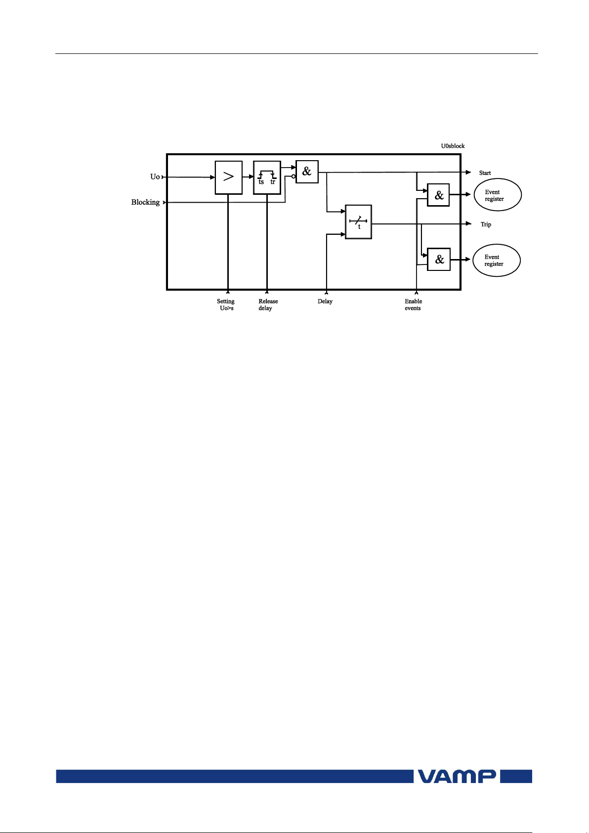
Technical description
2 Protection functions
2.9 Zero sequence voltage
protection U0> (59N)
VM59.EN001
VAMP 24h support phone +358 (0)20 753 3264
69
Setting groups
There are two settings groups available for both stages.
Switching between setting groups can be controlled by digital
inputs, virtual inputs (communication, logic) and manually.
Figure 2.9-1. Block diagram of the zero sequence voltage stages U0> and
U0>>
Page 70

2.9 Zero sequence voltage
protection U0> (59N)
2 Protection functions
Technical description
70
VAMP 24h support phone +358 (0)20 753 3264
VM59.EN001
Parameter
Value
Unit
Description
Note
Status
Blocked
Start
Trip
Current status of the stage
F
F
SCntr
Cumulative start counter
C
TCntr
Cumulative trip counter
C
SetGrp
1 or 2
Active setting group
Set
SGrpDI
-
DIx
VIx
LEDx
VOx
Fx
Digital signal to select the
active setting group
None
Digital input
Virtual input
LED indicator signal
Virtual output
Function key
Set
Force
Off
On
Force flag for status forcing
for test purposes. This is a
common flag for all stages and
output relays, too.
Automatically reset by a 5minute timeout.
Set
Uo %
The supervised value relative
to Un/3
Uo>, Uo>>
% Pick-up value relative to
Un/3
Set
t>, t>> s
Definite operation time
Set
Parameter
Value
Unit
Description
yyyy-mm-dd
Time stamp of the recording, date
hh:mm:ss.ms
Time stamp, time of day
Flt %
Fault voltage relative to Un/3
EDly %
Elapsed time of the operating time
setting. 100% = trip
SetGrp
1
2
Active setting group during fault
Parameters of the residual overvoltage stages
U0>, U0>> (59N)
For details of setting ranges see chapter 9.2.
Set = An editable parameter (password needed)
C = Can be cleared to zero
F = Editable when force flag is on
Recorded values of the latest eight faults
There are detailed information available of the eight latest
faults: Time stamp, fault voltage, elapsed delay and setting
group.
Recorded values of the residual overvoltage stages
U0>, U0>> (59N)
Page 71

Technical description
2 Protection functions
2.10 Thermal overload protection
T> (49)
VM59.EN001
VAMP 24h support phone +358 (0)20 753 3264
71
22
2
2
ln
aI
II
t
P
alarmIkka
Mode
Mode
Ikka
22
2
ln
Ia
I
Ct
P
MODE
Ika 95.0
alarmIka
MODE
95.0
T = Operation time
=
Thermal time constant tau (Setting value)
ln = Natural logarithm function
I = Measured rms phase current (the max. value of
three phase currents)
Ip
=
Preload current,
NP
IkI
(If temperature rise
is 120%
2.1
). This parameter is the memory of
the algorithm and corresponds to the actual
temperature rise.
k = Overload factor (Maximum continuous current), i.e.
service factor. (Setting value)
k
=
Ambient temperature factor (Permitted current due
to tamb) Figure 2-9.
I
MODE
=
The rated current (IN or I
MOT
)
C
=
Relay cooling time constant (Setting value)
2.10. Thermal overload protection T> (49)
The thermal overload function protects cables in the feeder
mode against excessive heating.
Thermal model
The temperature is calculated using rms values of phase
currents and a thermal model according IEC 60255-8. The rms
values are calculated using harmonic components up to the
15th.
Trip time:
Alarm:
Trip:
Release time:
Trip release:
Start release:
(Alarm 60% = 0.6)
(Alarm 60% = 0.6)
Time constant for cooling situation
If the motor's fan is stopped, the cooling will be slower than
with an active fan. Therefore there is a coefficient c for
thermal constant available to be used as cooling time constant,
when current is less than 0.3xI
MOT
.
Page 72
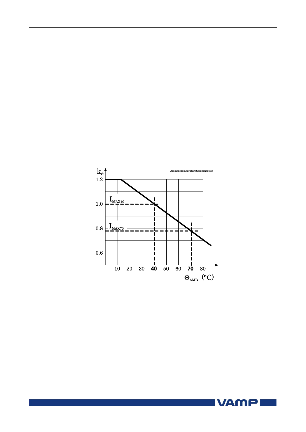
2.10 Thermal overload protection
T> (49)
2 Protection functions
Technical description
72
VAMP 24h support phone +358 (0)20 753 3264
VM59.EN001
MODEMAX
IkkI
Heat capacitance, service factor and ambient temperature
The trip level is determined by the maximum allowed
continuous current I
temperature rise
cable. I
temperature
depends of the given service factor k and ambient
MAX
and settings I
AMB
corresponding to the 100 %
MAX
i.e. the heat capacitance of the motor or
TRIP
MAX40
and I
according the
MAX70
following equation.
The value of ambient temperature compensation factor k
depends on the ambient temperature
and I
when k = 1. This is true when
I
MAX40
. See Figure 2-9. Ambient temperature is not in use
MAX70
is 1.0
and settings I
AMB
MAX40
Samb is “n/a” (no ambient temperature sensor)
TAMB is +40 °C.
Figure 2-9 Ambient temperature correction of the overload stage T>.
Example of a behaviour of the thermal model
Figure 2-10 shows an example of the thermal model behaviour.
In this example = 30 minutes, k = 1.06 and k = 1 and the
current has been zero for a long time and thus the initial
temperature rise is 0 %. At time = 50 minutes the current
changes to 0.85xI
and the temperature rise starts to
MODE
approach value (0.85/1.06)2 = 64 % according the time constant.
At time=300 min, the temperature is about stable, and the
current increases to 5 % over the maximum defined by the
rated current and the service factor k. The temperature rise
starts to approach value 110 %. At about 340 minutes the
temperature rise is 100 % and a trip follows.
Page 73
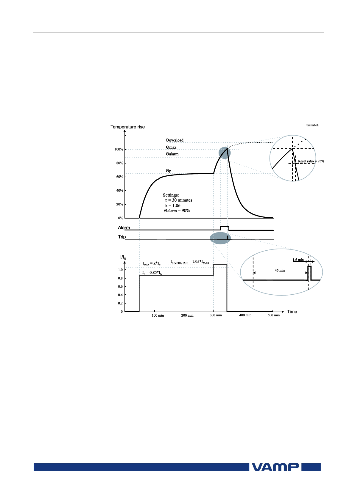
Technical description
2 Protection functions
2.10 Thermal overload protection
T> (49)
VM59.EN001
VAMP 24h support phone +358 (0)20 753 3264
73
Initial temperature rise after restart
When the device is switched on, an initial temperature rise of
70 % is used. Depending of the actual current, the calculated
temperature rise then starts to approach the final value.
Alarm function
The thermal overload stage is provided with a separately
settable alarm function. When the alarm limit is reached the
stage activates its start signal.
Figure 2-10 Example of the thermal model behaviour.
Page 74

2.10 Thermal overload protection
T> (49)
2 Protection functions
Technical description
74
VAMP 24h support phone +358 (0)20 753 3264
VM59.EN001
Parameter
Value
Unit
Description
Note
Status
Blocked
Start
Trip
Current status of the stage
F
F
Time
hh:mm:ss
Estimated time to trip
SCntr
Cumulative start counter
C
TCntr
Cumulative trip counter
C
Force
Off
On
Force flag for status forcing
for test purposes. This is a
common flag for all stages
and output relays, too.
Automatically reset by a 5minute timeout.
Set
T %
Calculated temperature
rise. Trip limit is 100 %.
F
MaxRMS
Arms
Measured current. Highest
of the three phases.
Imax A
kxIn. Current corresponding
to the 100 % temperature
rise.
k> xImode
Allowed overload (service
factor)
Set
Alarm %
Alarm level
Set
tau min
Thermal time constant
Set
ctau xtau
Coefficient for cooling time
constant. Default = 1.0
Set
kTamb
xImode
Ambient temperature
corrected max. allowed
continuous current
Imax40
%Imode
Allowed load at Tamb +40
C. Default = 100 %.
Set
Imax70
%Imode
Allowed load at Tamb +70
C.
Set
Tamb
C
Ambient temperature.
Editable Samb=n/a. Default
= +40 C
Set
Samb
n/a
ExtAI1...
16
Sensor for ambient
temperature
No sensor in use for Tamb
External Analogue input
1...16
Set
Parameters of the thermal overload stage T> (49)
For details of setting ranges see chapter 9.2.
Set = An editable parameter (password needed)
C = Can be cleared to zero
F = Editable when force flag is on
Page 75

Technical description
2 Protection functions
2.11 Circuit breaker failure stage
CBFP (50BF)
VM59.EN001
VAMP 24h support phone +358 (0)20 753 3264
75
Parameter
Value
Unit
Description
Note
Status
-
Blocked
Start
Trip
Current status of the stage
F
F
SCntr
Cumulative start counter
C
TCntr
Cumulative trip counter
C
Force
Off
On
Force flag for status forcing for
test purposes. This is a
common flag for all stages and
output relays, too.
Automatically reset by a 5minute timeout.
Set
Cbrelay
1
2
The supervised output relay*).
Relay T1
Relay T2
Set
t> s
Definite operation time.
Set
2.11. Circuit breaker failure stage CBFP
(50BF)
The circuit breaker failure protection can be used to trip any
upstream circuit breaker (CB), if the fault has not disappeared
within a given time after the initial trip command. A different
output contact of the device must be used for this backup trip.
The operation of the circuit-breaker failure protection (CBFP)
is based on the supervision of the signal to the selected trip
relay and the time the fault remains on after the trip command.
If this time is longer than the operating time of the CBFP
stage, the CBFP stage activates another output relay, which
will remain activated until the primary trip relay resets.
The CBFP stage is supervising all the protection stages using
the same selected trip relay, since it supervises the control
signal of this relay. See chapter 5.4 for details about the output
matrix and the trip relays.
Parameters of the circuit breaker failure stage CBFP (50BF)
For details of setting ranges see chapter 9.2.
Set = An editable parameter (password needed)
C = Can be cleared to zero
F = Editable when force flag is on
*) This setting is used by the circuit breaker condition monitoring, too. See
chapter 3.5.
Recorded values of the latest eight faults
There are detailed information available of the eight latest
faults: Time stamp and elapsed delay.
Page 76
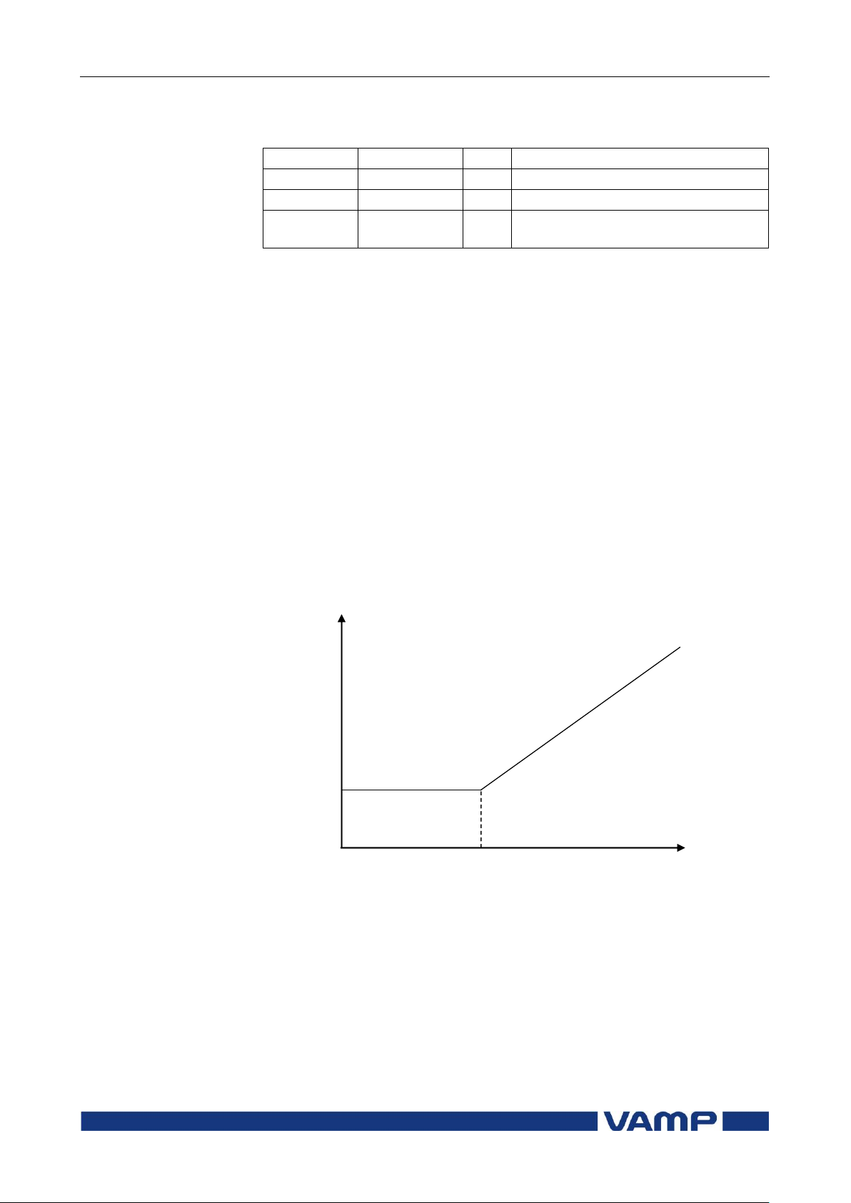
2.12 Line differential protection
LdI> (87L)
2 Protection functions
Technical description
76
VAMP 24h support phone +358 (0)20 753 3264
VM59.EN001
Parameter
Value
Unit
Description
yyyy-mm-dd
Time stamp of the recording, date
hh:mm:ss.ms
Time stamp, time of day
EDly %
Elapsed time of the operating time
setting. 100% = trip
dI
module
Phase current amplitude
Trip region
dI> pick-up
Basic setting
Slope
Start of slope (Basic limit)
Recorded values of the circuit breaker failure stage (8 latest
faults) CBFP (50BF)
2.12. Line differential protection LdI> (87L)
VAMP 59 relay is a differential protection device mainly
designed for sub-transmission overhead lines, medium voltage
cables and transformers. Two line ends may lie within the
protection zone.
Phase segregated protection is based on current (vector)
differential. Combination of both phase and magnitude
differential is used to determine operation. The differential
element takes a sampled version of the instantaneous current
waveform as its local input and compares it with a
corresponding current from the remote end. The signal is
converted to magnitude and angle information for comparison.
The threshold characteristics is biased for CT saturation as
presented in
.
Page 77
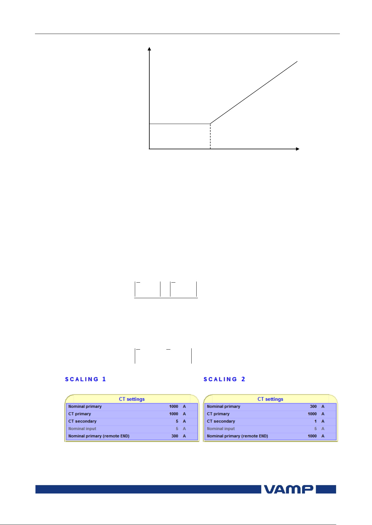
Technical description
2 Protection functions
2.12 Line differential protection
LdI> (87L)
VM59.EN001
VAMP 24h support phone +358 (0)20 753 3264
77
dI
module
Phase current amplitude
Trip region
dI> pick-up
Basic setting
Slope
Start of slope (Basic limit)
2
21 RELAYRELAY
b
II
I
21 RELAYRELAY
d
III
Figure 2.12-1 Tripping threshold characteristics
Bias current calculation is only used in protection stage I>.
Bias current describes the average current flow in transformer.
Bias and differential currents are calculated individually for
each phase.
Equation 2.12-1: Bias current
Equation 2.12-2: Differential current
Figure 2.12-2 Example settings
Page 78

2.12 Line differential protection
LdI> (87L)
2 Protection functions
Technical description
78
VAMP 24h support phone +358 (0)20 753 3264
VM59.EN001
Nd
II 00101
Nd
II 37.91357354.2
Nb
II
1
2
11
Nb
II
7.4
2
74.2
Example 1:Normal situation from relay 1 point of view
Relay1: measured phase current IL1=1000A/0°.
Relay2: measured phase current IL1=300A/-180°.
CT scaling of relay1 is 1000A / 5A and nominal current is
1000A. CT scaling of relay2 is 1000A / 1A and the nominal
current is 300A. Relay2 sends primary current measurement
information to relay1 and relay1 swaps the angle of received
current by 180 degrees (relay2 phase current IL1=300A/-180°
300A/0°).
In BIAS-calculation the measured current amplitude is divided
by the nominal primary current of both ends (might be
different like now).
Relay1: I
Relay2: I
PRIMARY MEASURED
PRIMARY RECEIVED
/ I
NOMINAL
/ I
NOMINAL REMOTE
= 1000A / 1000A = 1
= 300A / 300A = 1
Example 2:Fault situation from relay 1 point of view
Relay1: measured phase current IL1=2400A/-30°.
Relay2: measured phase current IL1=2100A/-45°.
CT scaling of relay1 is 1000A / 5A and nominal current is
1000A. CT scaling of relay2 is 1000A / 1A and the nominal
current is 300A. Relay2 sends primary current measurement
information to relay1 and relay1 swaps the angle of received
current by 180 degrees (relay2 phase current IL1=2100A/-45°
2100A/135°).
In BIAS-calculation the measured current amplitude is divided
by the nominal primary current of both ends (might be
different like now).
Relay1: I
Relay2: I
PRIMARY MEASURED
PRIMARY RECEIVED
/ I
NOMINAL
/ I
NOMINAL REMOTE
= 2400A / 1000A = 2.4
= 2100A / 300A = 7
Page 79
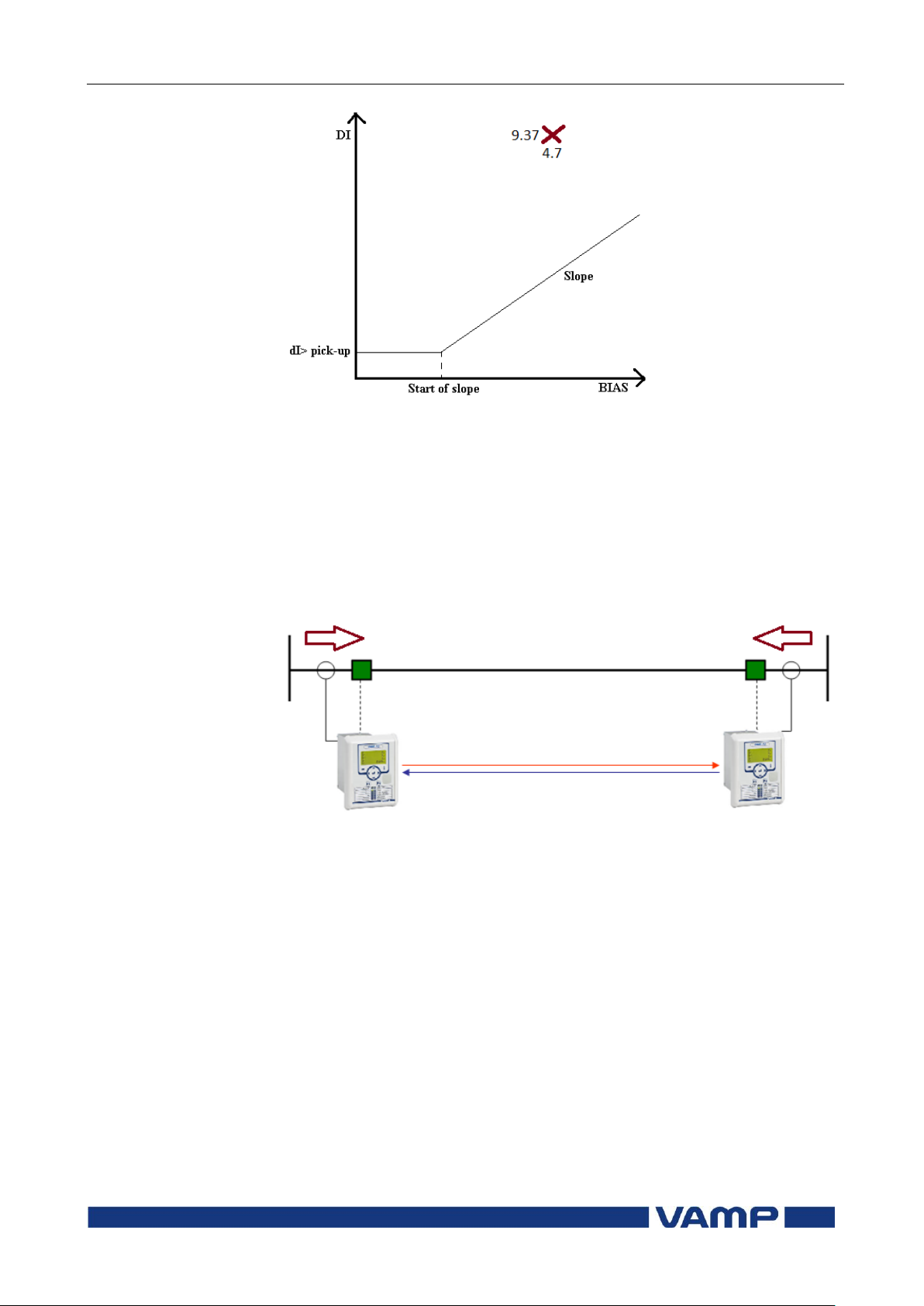
Technical description
2 Protection functions
2.12 Line differential protection
LdI> (87L)
VM59.EN001
VAMP 24h support phone +358 (0)20 753 3264
79
Figure 2.12-3 Example BIAS and differential calculation
Data communication for differential current measurement is
effected via fibre-optic cables. 1550 nm single-mode fibre
provides communication up „till 120 km with external
communication modules.
Relay has special setting called “Line distance”. This setting
compensates the time delay between the relay caused by the
optic fiber. In case that the length of the fibre is 90 km the
setting has to be 90km as well.
Figure 2.12-4 CT wiring towards the line
The starting times of the phase currents calculation tasks in
two relays are synchronized. Function will block tripping until
the synchronization is achived. The default communication
speed is 64000 bps.
Serial remote port of the relay (RS-232) is used by line
differential protection. The recommended solution for the
communication channel is the supervised fibre optic wiring.
With multimode fibre cables and VSE001-GG fibre optic
modems the communication distance can be up to 1 km. When
using single mode fibre cables and third party converters the
distance can be up to tens of kilometres.
Page 80
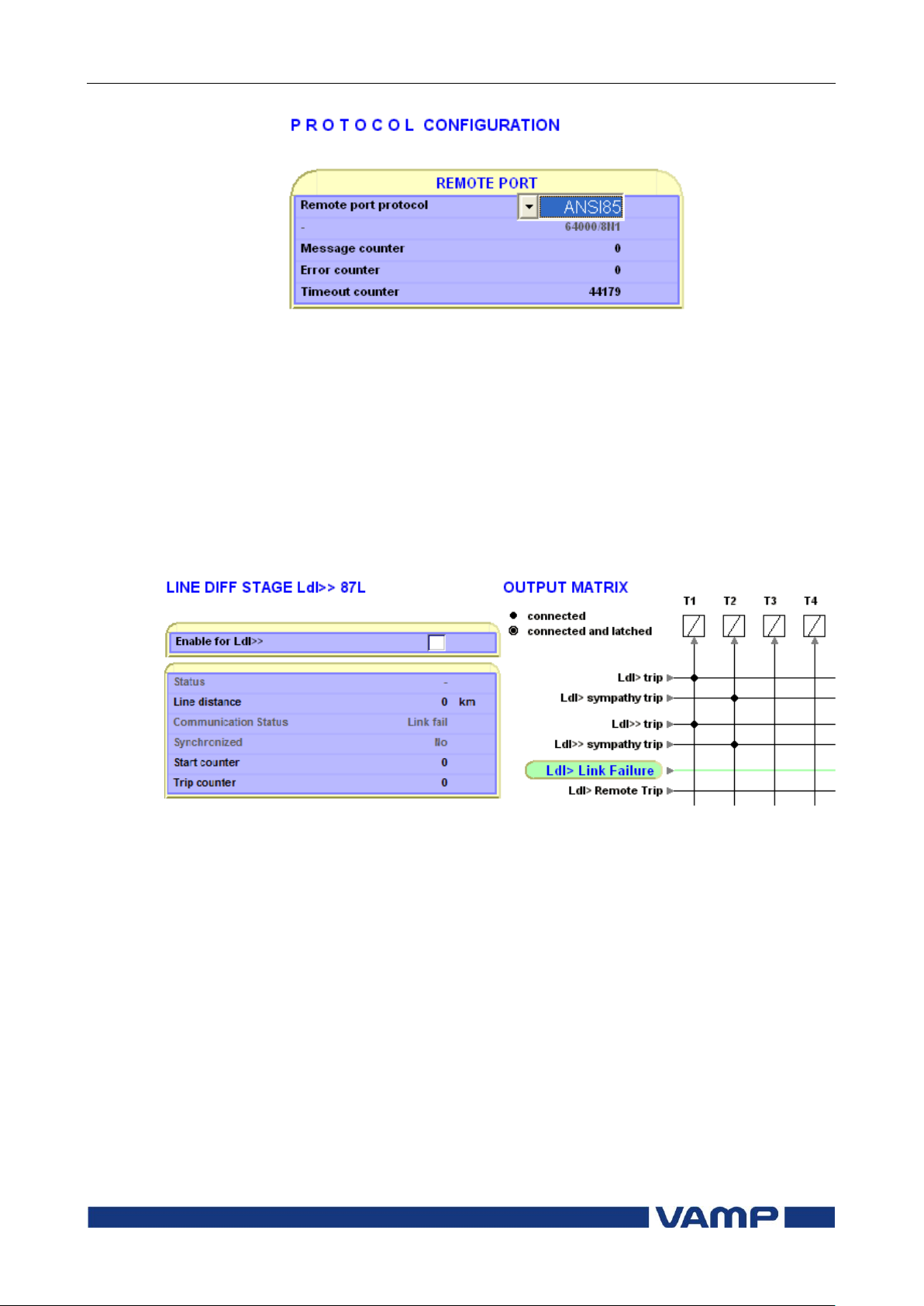
2.12 Line differential protection
LdI> (87L)
2 Protection functions
Technical description
80
VAMP 24h support phone +358 (0)20 753 3264
VM59.EN001
Figure 2.12-5 Enabling line differential communication
Line differential protection has no operation delay. When the
difference between phase currents has been greater than the
threshold for two task cycles, the device will trip. Typical
tripping time in fault situation is 35 ms.
In case of the communcation channel failure the line
differential protection is inactive.
Line differential trip signal as well as communication channel
failure status are available as inputs in the output matrix and
blocking matrix of the relay.
Figure 2.12-6 Communication failure
The communication channel between two line differential
protection relays carries also binary signals in both directions:
the status of LDP trip signals, and the remote trip command
signal which is an output from the output logic matrix of the
sending relay. Remote trip signal can be processed as an input
in the output matrix and blocking matrix of the receiving relay.
Up to 16 binary signals can be sent between the relays. Signals
are updated every 10 ms. POC-signals are tied to line
differential algorithm which is operating after every half cycle
(50Hz).
Page 81
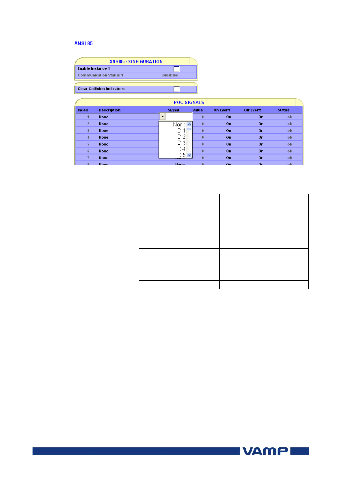
Technical description
2 Protection functions
2.12 Line differential protection
LdI> (87L)
VM59.EN001
VAMP 24h support phone +358 (0)20 753 3264
81
Parameter
Value/unit
Description
Setting
values
dI> pick-up
In
Basic setting for lower phase
currents
Start of slope
In
Phase current limit for
applying linear threshold
characteristics
Slope
%
Linear characteristics slope
CT primary
(remote END)
[10 ..
20000]
CT ratio of the other unit
Default 500
Recorded
values
TCntr
Trip counter (Trip) reading
LdI> status
Protection state
Synchronized
Synchronization status
Figure 2.12-7 Up to 16 event stamped binary signals
Parameters of the line differential protection stage LdI> (87L):
In VAMP59 current comparison is based to nominal primary
currents of both ends. In line or cable differential protection
“nominal primary” value should be the same the “CT primary”
value.
When it comes to transformer protection it is normal that
nominal current of the transformer differs of the CT nominal
which is higher. To ensure correct differential calculation it is
important to know the nominal current of the other end as well.
When there is transformer on the line or VAMP59 is used
mainly to transformer differential protection, it is possible to
select correct connection group and whether the relay is on
high voltage (HV) or low voltage side (LV).
Page 82
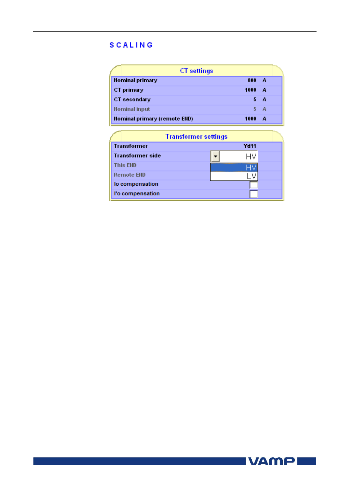
2.12 Line differential protection
LdI> (87L)
2 Protection functions
Technical description
82
VAMP 24h support phone +358 (0)20 753 3264
VM59.EN001
Figure 2.12-8 VAMP59 CT –and transformer settings
If transformer is earthed, e.g. connection group Dyn11, then
zero current must be compensated before differential and bias
current calculation. Zero current compensation can be selected
individually for own and remote side. (Io -compensation is
available 2012).
Page 83

Technical description
2 Protection functions
2.12 Line differential protection
LdI> (87L)
VM59.EN001
VAMP 24h support phone +358 (0)20 753 3264
83
Transformator
Relay setting
Connection group
ConnGrp
Io cmps
I'o cmps
YNy0
Yy0
ON
OFF
YNyn0
Yy0
ON
ON
Yy0
Yy0
OFF
OFF
Yyn0
Yy0
OFF
ON
YNy6
Yy6
ON
OFF
YNyn6
Yy6
ON
ON
Yy6
Yy6
OFF
OFF
Yyn6
Yy6
OFF
ON
Yd1
Yd1
OFF
OFF
YNd1
Yd1
ON
OFF
Yd5
Yd5
OFF
OFF
YNd5
Yd5
ON
OFF
Yd7
Yd7
OFF
OFF
YNd7
Yd7
ON
OFF
Yd11
Yd11
OFF
OFF
YNd11
Yd11
ON
OFF
Dy1
Dy1
OFF
OFF
Dyn1
Dy1
OFF
ON
Dy5
Dy5
OFF
OFF
Dyn5
Dy5
OFF
ON
Dy7
Dy7
OFF
OFF
Dyn7
Dy7
OFF
ON
Dy11
Dy11
OFF
OFF
Dyn11
Dy11
OFF
ON
Table 2.12-1 Zero current compensation in transformer applications
Page 84
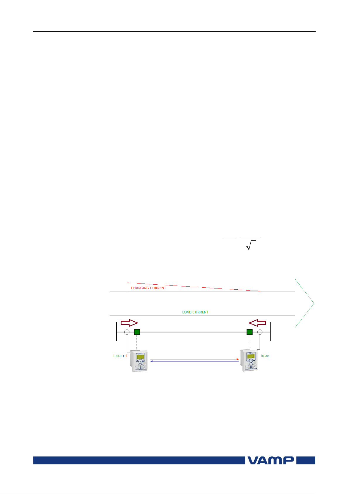
2.12 Line differential protection
LdI> (87L)
2 Protection functions
Technical description
84
VAMP 24h support phone +358 (0)20 753 3264
VM59.EN001
3
102
fCUlI
C
3
10
3
15
23.05014.3232
kV
km
F
HzkmI
C
2.12.1. Capacitive charging current
Major charging currents can be expected on cable or hybrid
feeders. The charging current of the cable will increase
according the lengt of the circuit. The capacitive charging
current leads the feeder load current and therefore is causing
differential (phase and magnitude) to the protected feeder.
Steady state difference in currents will have an impact on the
minimum differential settings that may be used.
Equation 2.12.1-1: Capacitive charging current
Where:
l = Cable length (km)
IC = Charging current (amperes)
f = Frequency
C = Cable capacitance ( µF / km)
U = Voltage to neutral (kV)
Example: 32km of certain 15kV cable:
will cause about 20A of constant charging current. In this case
differential stage should be set above 20A.
Figure 2.12.1-1 Behaviour of constant charging current
NOTE! When cable feeder is energized there will be significant transient
charging current. The frequency of this transient is above basic
component and does not effect to the differential calculation.
Page 85
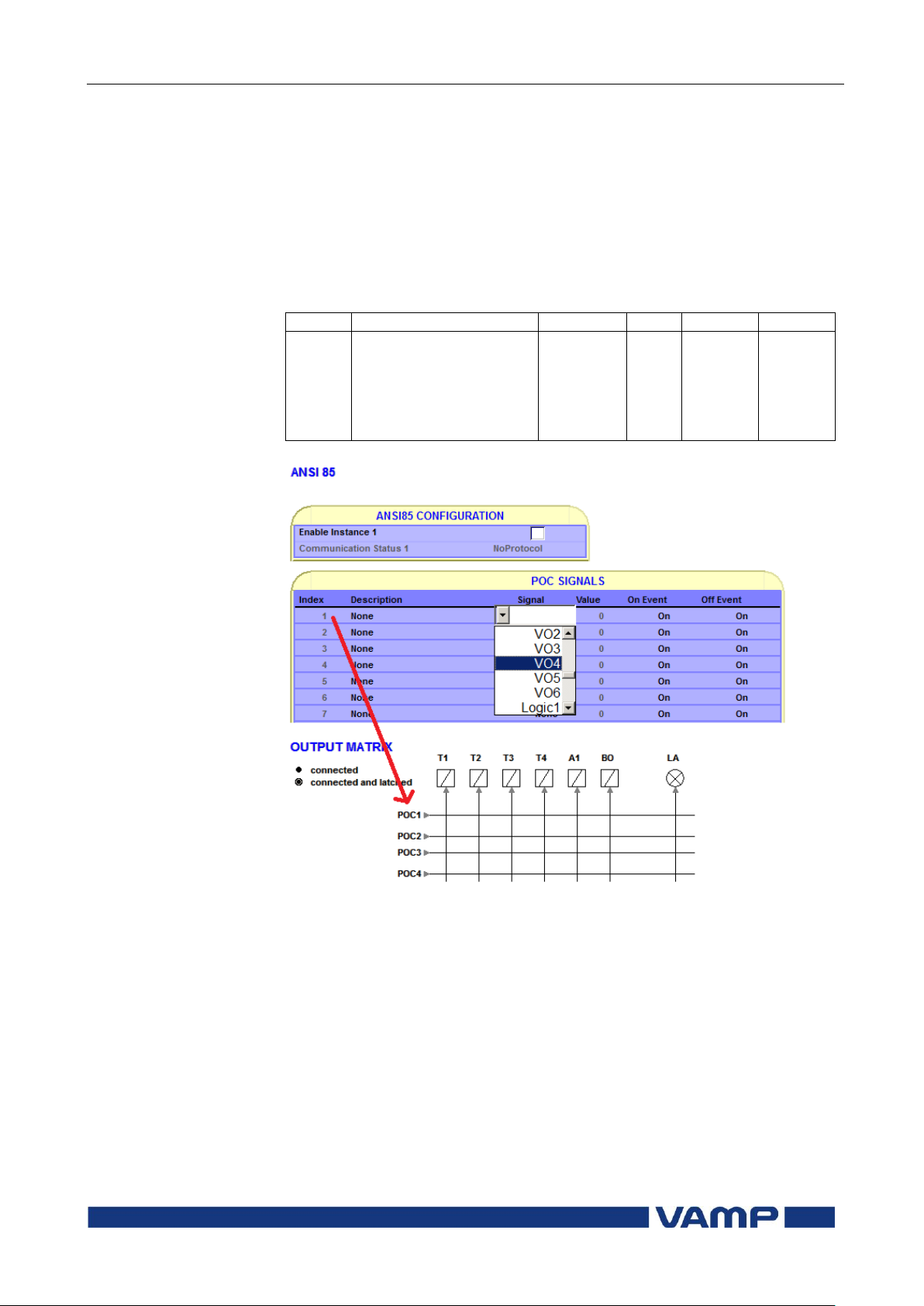
Technical description
2 Protection functions
2.12 Line differential protection
LdI> (87L)
VM59.EN001
VAMP 24h support phone +358 (0)20 753 3264
85
Index
Description
Signal
Value
On event
Off event
1 - 16
User selectable name
for the signal (None as
a default)
None
DI1-n
VI1-4
VO1-6
Logic1-20
0…1
on…off
on…off
2.12.2. ANSI 85 (POC –signals)
Total of 16 signals can be sent between two VAMP59 line
differential relays via ANSI 85 communication. Basically it
means when relay is using 8 of the signals there is still 8 more
signals left for the other end. Signal status is updated every 10
ms.
List of POC –signals between the relays (ANSI 85):
Figure 2.12.2-1 Selecting POC –signals
ANSI 85 communication has to be enabled between the relays
to transfer POC –signals. This is done by activating “Enable
instance 1”. When for example DI1 is selected as a signal it‟s
value remains 0 as long as DI1 is acticated. Activated signal in
index 1 activates the POC1 of the other relay in output matrix.
Signal is also visible in logic and other matrixes.
Communication status is “NoProtocol” when ANSI 85 is not
selected to remote port in protocol configuration –menu,
“Disable” when not activated and “OK” when instance 1 is
enabled.
Page 86

2.13 Programmable stages (99)
2 Protection functions
Technical description
86
VAMP 24h support phone +358 (0)20 753 3264
VM59.EN001
Priority
If operation times less than 60 milliseconds are needed
select 10 ms. For operation times under one second 20 ms
is recommended. For longer operation times and THD
signals 100 ms is recommended.
Link
The name of the supervised signal (see table below).
Cmp
Compare mode. „>‟ for over or „<‟ for under comparison.
Pick-up
Limit of the stage. The available setting range and the unit
depend on the selected signal.
T
Definite time operation delay
Hyster
Dead band (hysteresis)
NoCmp
Only used with compare mode under („<‟). This is the limit
to start the comparison. Signal values under NoCmp are
not regarded as fault.
2.13. Programmable stages (99)
For special applications the user can built his own protection
stages by selecting the supervised signal and the comparison
mode.
The following parameters are available:
Page 87

Technical description
2 Protection functions
2.13 Programmable stages (99)
VM59.EN001
VAMP 24h support phone +358 (0)20 753 3264
87
IL1, IL2, IL3
Phase currents
IL1REM,
IL2REM,
IL3REM
Remote end phase currents
Io
Residual current input I0
Uo
Zero sequence voltage
f
Frequency
IoCalc
Phasor sum IL1 + IL2 + IL3
I1
Positive sequence current
I2
Negative sequence current
I2/I1
Relative negative sequence current
I2/In
Negative sequence current in pu
T
Thermal status
IL
Average (IL1 + IL2 + I
L3)
/3
ILmin
Minimum of phase currents
ILmax
Maximum of phase currents
THDIL1
Total harmonic distortion of IL1
THDIL2
Total harmonic distortion of IL2
THDIL3
Total harmonic distortion of IL3
IL1RMS
IL1 RMS for average sampling
IL2RMS
IL2 RMS for average sampling
IL3RMS
IL3 RMS for average sampling
Io1RMS
Io1 RMS for average sampling
Table 2.13-1 Available signals to be supervised by the programmable stages
Eight independent stages
The device has eight independent programmable stages. Each
programmable stage can be enabled or disabled to fit the
intended application.
Setting groups
There are two settings groups available. Switching between
setting groups can be controlled by digital inputs, virtual
inputs (communication, logic) and manually.
There are two identical stages available with independent
setting parameters.
Page 88

2.13 Programmable stages (99)
2 Protection functions
Technical description
88
VAMP 24h support phone +358 (0)20 753 3264
VM59.EN001
Parameter
Value
Unit
Description
Note
Enable for
Prg”n”
Enaled
Disabled
Activation of the
programmable stage
Set
Priority
ms
Software task priority of the
protected stage
Set
Status
Blocked
Start
Trip
Current status of the stage
F
F
Force
Off
On
Force flag for status forcing
for test purposes. This is a
common flag for all stages and
output relays, too.
Automatically reset by a 5minute timeout.
Set
Timebase
for input
value
cycletime of the selected
protection signal
Set
Coupling
Selected protection signal
Set
Value
Current primary value of the
selected protection signal
Cmp
>
<
Mode of comparison
Over protection
Under protection
Set
SetGrp
1 or 2
Active setting group
Set
SGrpDI
-
DIx
VIx
LEDx
VOx
Fx
Digital signal to select the
active setting group
None
Digital input
Virtual input
LED indicator signal
Virtual output
Function key
Set
Pickup
Pick up value scaled to
primary level
Pickup
pu
Pick up setting in pu
Set
t s
Definite operation time.
Set
Hyster
% Dead band setting
Set
NoCmp
pu
Minimum value to start under
comparison. (Mode='<')
Set
Parameters of the programmable stages PrgN (99)
Set = An editable parameter (password needed)
C = Can be cleared to zero
F = Editable when force flag is on
Recorded values of the latest eight faults
There is detailed information available of the eight latest
faults: Time stamp, fault value and elapsed delay.
Page 89

Technical description
2 Protection functions
2.14 Inverse time operation
VM59.EN001
VAMP 24h support phone +358 (0)20 753 3264
89
Parameter
Value
Unit
Description
yyyy-mm-dd
Time stamp of the recording, date
hh:mm:ss.ms
Time stamp, time of day
Flt pu
Fault value
EDly %
Elapsed time of the operating time
setting. 100% = trip
SetGrp
1
2
Active setting group during fault
Recorded values of the programmable stages PrgN (99)
2.14. Inverse time operation
The inverse time operation - i.e. inverse delay minimum time
(IDMT) type of operation - is available for several protection
functions. The common principle, formulae and graphic
representations of the available inverse delay types are
described in this chapter.
Inverse delay means that the operation time depends on the
measured real time process values during a fault. For example
with an overcurrent stage using inverse delay a bigger fault
current gives faster operation. The alternative to inverse delay
is definite delay. With definite delay a preset time is used and
the operation time does not depend on the size of a fault.
Operation modes
There are three operation modes to use the inverse time
characteristics:
Standard delays
Using standard delay characteristics by selecting a curve
family (IEC, IEEE, IEEE2, RI) and a delay type (Normal
inverse, Very inverse etc). See chapter 2.14.1.
Standard delay formulae with free parameters
selecting a curve family (IEC, IEEE, IEEE2) and defining
one's own parameters for the selected delay formula. This
mode is activated by setting delay type to „Parameters‟, and
then editing the delay function parameters A ... E. See
chapter 2.14.2.
Fully programmable inverse delay characteristics
Building the characteristics by setting 16 [current, time]
points. The relay interpolates the values between given
points with 2nd degree polynomials. This mode is activated
by setting curve family to „PrgN‟'. There are maximum three
different programmable curves available at the same time.
Each programmed curve can be used by any number of
protection stages. See chapter 2.14.3.
Page 90

2.14 Inverse time operation
2 Protection functions
Technical description
90
VAMP 24h support phone +358 (0)20 753 3264
VM59.EN001
Current input
Maximum measured
secondary current
Maximum secondary
scaled setting
enabling inverse delay
times up to full 20x
setting
IL1, IL2, IL3 and I
0Calc
250 A
12.5 A
I01 5 A
50 A
2.5 A
I01 1 A
10 A
0.5 A
I01 0.2 A
2 A
0.1 A
Inverse time setting error signal
If there are any errors in the inverse delay configuration the
appropriate protection stage will use definite time delay.
There is a signal „Setting Error‟ available in output matrix,
which indicates three different situations:
1. Settings are currently changed with VAMPSET or local
panel, and there is temporarily an illegal combination of
curve/delay/points. For example if previous settings were
IEC/NI and then curve family is changed to IEEE, the
setting error will activate, because there is no NI type
available for IEEE curves. After changing valid delay type
for IEEE mode (for example MI), the „Setting Error‟ signal
will release.
2. There are errors in formula parameters A…E, and the
device is not able to build the delay curve
3. There are errors in the programmable curve configuration
and the device is not able to interpolate values between the
given points.
Limitations
The maximum measured secondary phase current is 50xIN and
the maximum directly measured earth fault current is 10xI0N
for residual current inputs. The full scope of inverse delay
curves goes up to 20 times the setting. At high setting the
maximum measurement capability limits the scope of inverse
curves according the following table.
Table 2.14-1
Page 91

Technical description
2 Protection functions
2.14 Inverse time operation
VM59.EN001
VAMP 24h support phone +358 (0)20 753 3264
91
Example 1 of limitation
CT = 750/5
CT0 = 100/1 (cable CT is used for residual current)
The CT0 is connected to a 1 A terminals of input I01.
For overcurrent stage I> the table above gives 12.5 A. Thus the
maximum setting for I> stage giving full inverse delay range is
12.5 A / 5 A = 2.5 xIN = 1875 A
PRIMARY
.
For earth fault stage I0> the table above gives 0.5 A. Thus the
maximum setting for I0> stage giving full inverse delay range is
0.5 A / 1 A = 0.5 xI0N = 50 A
PRIMARY
.
2.14.1. Standard inverse delays IEC, IEEE, IEEE2, RI
The available standard inverse delays are divided in four
categories IEC, IEEE, IEEE2 and RI called delay curve
families. Each category of family contains a set of different
delay types according the following table.
Inverse time setting error signal
The inverse time setting error signal will be activated, if the
delay category is changed and the old delay type doesn't exist
in the new category. See chapter 2.14 for more details.
Limitations
The minimum definite time delay start latest, when the
measured value is twenty times the setting. However, there are
limitations at high setting values due to the measurement
range. See chapter 2.14 for more details.
Page 92
2.14 Inverse time operation
2 Protection functions
Technical description
92
VAMP 24h support phone +358 (0)20 753 3264
VM59.EN001
Delay type
Curve family
DT
IEC
IEEE
IEEE2
RI
DT
Definite time
X
NI1
Normal inverse
X X
VI
Very inverse
X X X
EI
Extremely inverse
X X X
LTI
Long time inverse
X X
LTEI
Long time extremely inverse
X
LTVI
Long time very inverse
X
MI
Moderately inverse
X X
STI
Short time inverse
X
STEI
Short time extremely inverse
X
RI
Old ASEA type
X
RXIDG
Old ASEA type
X
1
B
PICKUP
I
I
Ak
t
Table 2.14.1-1Available standard delay families and the
available delay types within each family.
IEC inverse time operation
The operation time depends on the measured value and other
parameters according Equation 2.14.1-1. Actually this equation
can only be used to draw graphs or when the measured value I
is constant during the fault. A modified version is implemented
in the relay for real time usage.
Equation 2.14.1-1
t = Operation delay in seconds
k = User‟s multiplier
I = Measured value
I
PICKUP
A, B = Constants parameters according Table 2.14.1-2.
= User‟s pick up setting
There are three different delay types according IEC 60255-3,
Normal inverse (NI), Extremely inverse (EI), Very inverse (VI)
and a VI extension. Additional there is a de facto standard
Long time inverse (LTI).
Page 93
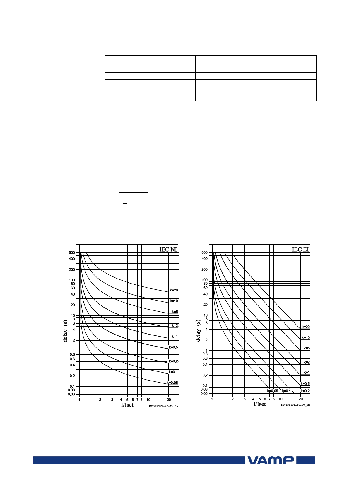
Technical description
2 Protection functions
2.14 Inverse time operation
VM59.EN001
VAMP 24h support phone +358 (0)20 753 3264
93
Delay type
Parameter
A
B
NI
Normal inverse
0.14
0.02
EI
Extremely inverse
80
2
VI
Very inverse
13.5
1
LTI
Long time inverse
120
1
0.5
1
2
4
14.050.0
02.0
t
Figure 2.14.1-1 IEC normal inverse delay.
Figure 2.14.1-2 IEC extremely inverse
delay.
Table 2.14.1-2 Constants for IEC inverse delay equation
Example for Delay type "Normal inverse (NI) ":
k = 0.50
I = 4 pu (constant current)
I
PICKUP
= 2 pu
A = 0.14
B = 0.02
The operation time in this example will be 5 seconds. The same
result can be read from Figure 2.14.1-1.
Page 94
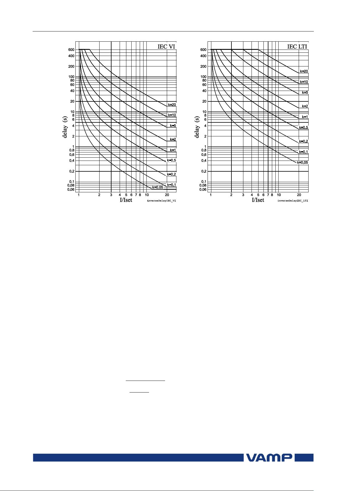
2.14 Inverse time operation
2 Protection functions
Technical description
94
VAMP 24h support phone +358 (0)20 753 3264
VM59.EN001
Figure 2.14.1-3 IEC very inverse delay.
Figure 2.14.1-4 IEC long time inverse
delay.
B
I
I
A
kt
C
PICKUP
1
IEEE/ANSI inverse time operation
There are three different delay types according IEEE Std
C37.112-1996 (MI, VI, EI) and many de facto versions
according Table 2.14.1-3. The IEEE standard defines inverse
delay for both trip and release operations. However, in the
VAMP relay only the trip time is inverse according the
standard but the release time is constant.
The operation delay depends on the measured value and other
parameters according Equation 2.14.1-2. Actually this equation
can only be used to draw graphs or when the measured value I
is constant during the fault. A modified version is implemented
in the relay for real time usage.
Equation 2.14.1-2
Page 95

Technical description
2 Protection functions
2.14 Inverse time operation
VM59.EN001
VAMP 24h support phone +358 (0)20 753 3264
95
Delay type
Parameter
A B C
LTI
Long time inverse
0.086
0.185
0.02
LTVI
Long time very inverse
28.55
0.712
2
LTEI
Long time extremely
inverse
64.07
0.250
2
MI
Moderately inverse
0.0515
0.1140
0.02
VI
Very inverse
19.61
0.491
2
EI
Extremely inverse
28.2
0.1217
2
STI
Short time inverse
0.16758
0.11858
0.02
STEI
Short time extremely
inverse
1.281
0.005
2
9.11140.0
1
2
4
0515.0
50.0
02.0
t
t = Operation delay in seconds
k = User‟s multiplier
I = Measured value
I
PICKUP
= User‟s pick up setting
A,B,C = Constant parameter according Table 2.14.1-3.
Table 2.14.1-3 Constants for IEEE/ANSI inverse delay equation
Example for Delay type "Moderately inverse (MI)":
k = 0.50
I = 4 pu
I
PICKUP
= 2 pu
A = 0.0515
B = 0.114
C = 0.02
The operation time in this example will be 1.9 seconds. The
same result can be read from Figure 2.14.1-8.
Page 96
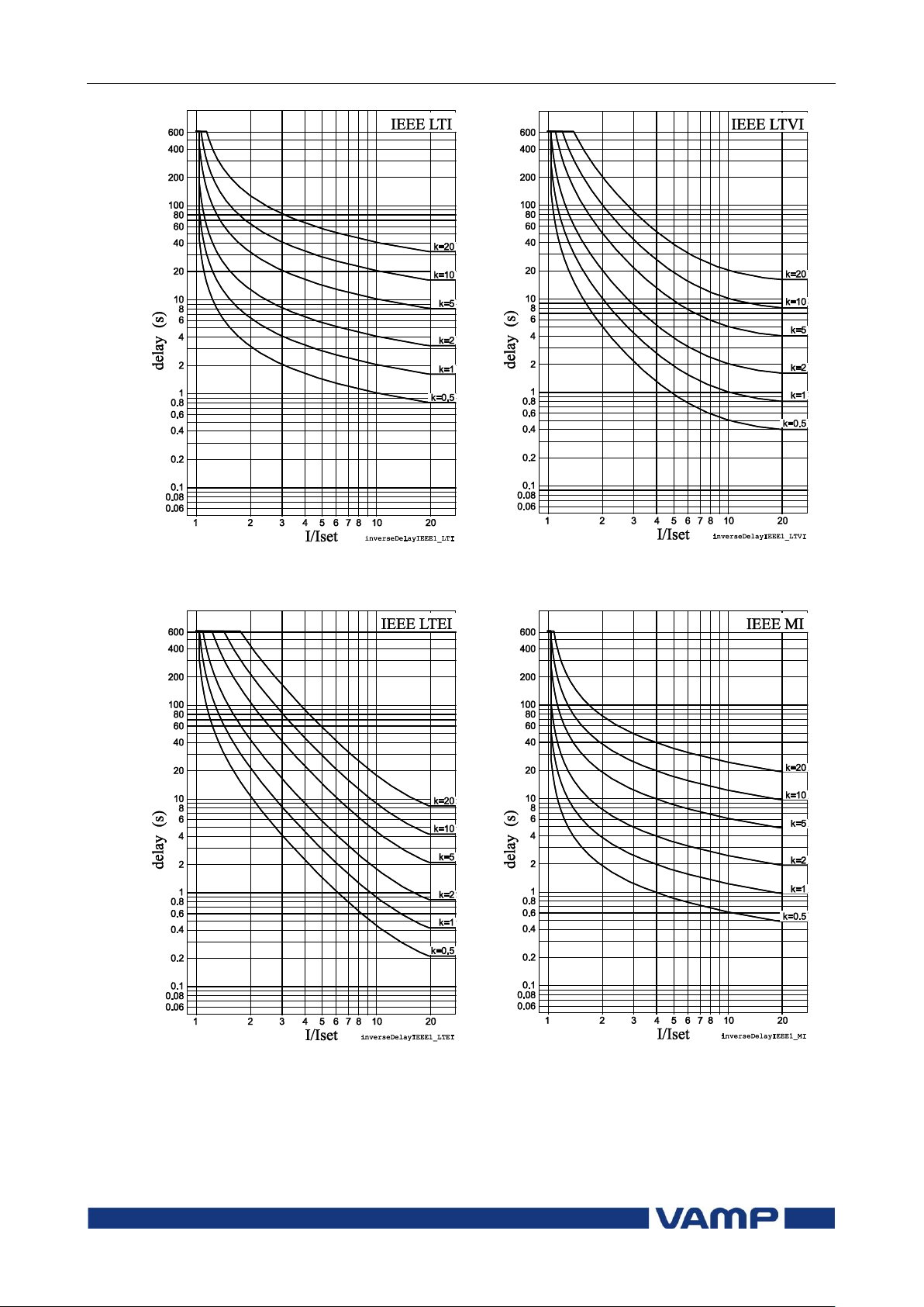
2.14 Inverse time operation
2 Protection functions
Technical description
96
VAMP 24h support phone +358 (0)20 753 3264
VM59.EN001
Figure 2.14.1-5 ANSI/IEEE long time inverse
delay
Figure 2.14.1-6 ANSI/IEEE long time very
inverse delay
Figure 2.14.1-7 ANSI/IEEE long time
extremely inverse delay
Figure 2.14.1-8 ANSI/IEEE moderately
inverse delay
Page 97
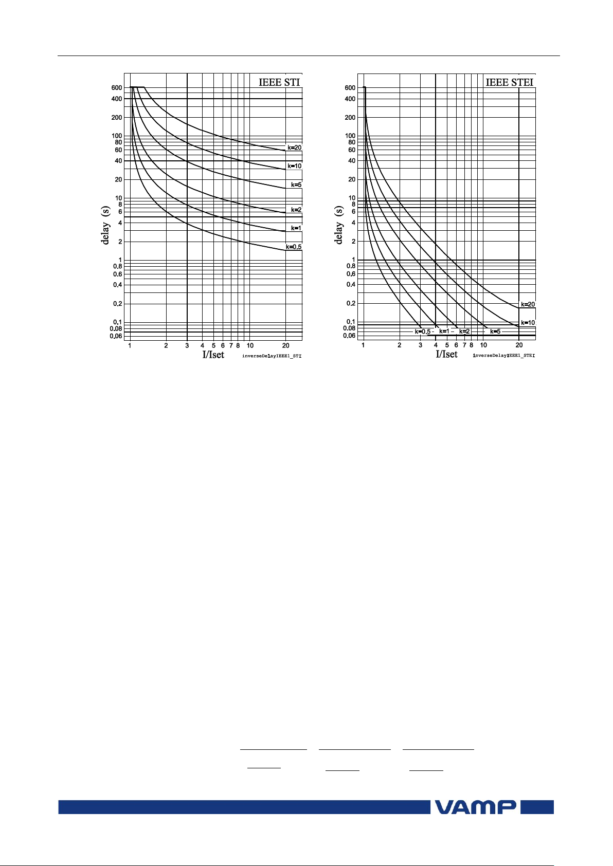
Technical description
2 Protection functions
2.14 Inverse time operation
VM59.EN001
VAMP 24h support phone +358 (0)20 753 3264
97
Figure 2.14.1-9 ANSI/IEEE short time inverse
delay
Figure 2.14.1-10 ANSI/IEEE short time
extremely inverse delay
3
PICKUP
2
PICKUP
PICKUP
C
I
I
E
C
I
I
D
C
I
I
B
Akt
IEEE2 inverse time operation
Before the year 1996 and ANSI standard C37.112
microprocessor relays were using equations approximating the
behaviour of various induction disc type relays. A quite popular
approximation is Equation 2.14.1-3, which in VAMP relays is
called IEEE2. Another name could be IAC, because the old
General Electric IAC relays have been modeled using the same
equation.
There are four different delay types according
Table 2.14.1-4. The old electromechanical induction disc relays
have inverse delay for both trip and release operations.
However, in VAMP relays only the trip time is inverse the
release time being constant.
The operation delay depends on the measured value and other
parameters according Equation 2.14.1-3. Actually this equation
can only be used to draw graphs or when the measured value I
is constant during the fault. A modified version is implemented
in the relay for real time usage.
Equation 2.14.1-3
Page 98

2.14 Inverse time operation
2 Protection functions
Technical description
98
VAMP 24h support phone +358 (0)20 753 3264
VM59.EN001
Delay type
Parameter
A B C D E
MI
Moderately inverse
0.1735
0.6791
0.8
-0.08
0.1271
NI
Normally inverse
0.0274
2.2614
0.3
-.1899
9.1272
VI
Very inverse
0.0615
0.7989
0.34
-0.284
4.0505
EI
Extremely inverse
0.0399
0.2294
0.5
3.0094
0.7222
38.0
8.0
2
4
127.0
8.0
2
4
08.0
8.0
2
4
6791.0
1735.05.0
32
t
t = Operation delay in seconds
k = User‟s multiplier
I = Measured value
I
PICKUP
= User‟s pick up setting
A,B,C,D = Constant parameter according
Table 2.14.1-4.
Table 2.14.1-4 Constants for IEEE2 inverse delay equation
Example for Delay type "Moderately inverse (MI)":
k = 0.50
I = 4 pu
I
PICKUP
= 2 pu
A = 0.1735
B = 0.6791
C = 0.8
D = -0.08
E = 0.127
The operation time in this example will be 0.38 seconds. The
same result can be read from Figure 2.14.1-11.
Page 99
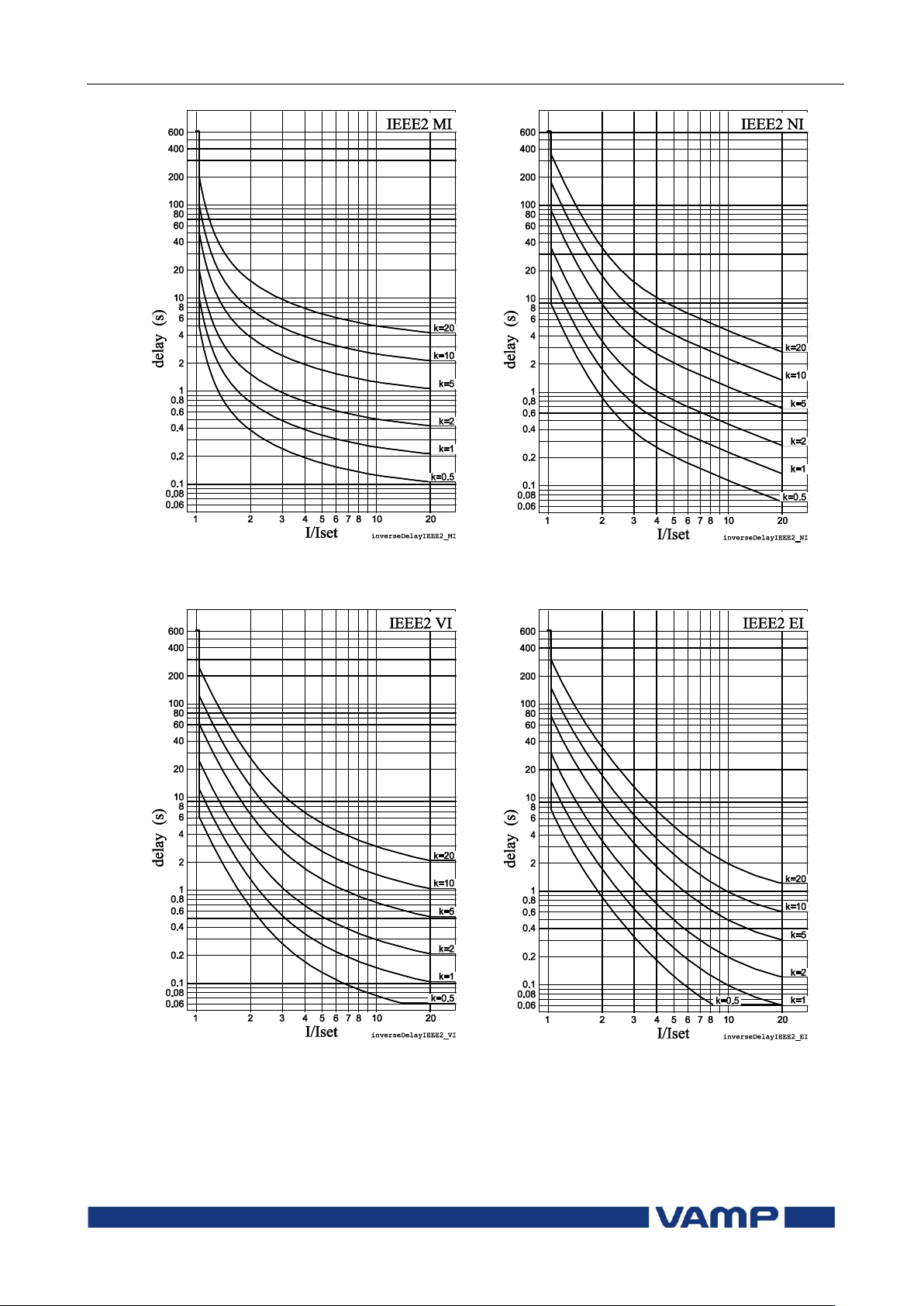
Technical description
2 Protection functions
2.14 Inverse time operation
VM59.EN001
VAMP 24h support phone +358 (0)20 753 3264
99
Figure 2.14.1-11 IEEE2 moderately inverse
delay
Figure 2.14.1-12 IEEE2 normal inverse
delay
Figure 2.14.1-13 IEEE2 very inverse delay
Figure 2.14.1-14 IEEE2 extremely inverse
delay
Page 100

2.14 Inverse time operation
2 Protection functions
Technical description
100
VAMP 24h support phone +358 (0)20 753 3264
VM59.EN001
PICKUP
236.0
339.0
I
I
k
t
RI
PICKUP
ln35.18.5
Ik
I
t
RXIDG
3.2
2
4
236.0
339.0
5.0
RI
t
9.3
25.0
4
ln35.18.5
RXIDG
t
RI and RXIDG type inverse time operation
These two inverse delay types have their origin in old ASEA
(nowadays ABB) earth fault relays.
The operation delay of types RI and RXIDG depends on the
measured value and other parameters according Equation
2.14.1-4 and Equation 2.14.1-5. Actually these equations can
only be used to draw graphs or when the measured value I is
constant during the fault. Modified versions are implemented
in the relay for real time usage.
Equation 2.14.1-4 RI
Equation 2.14.1-5 RXIDG
t = Operation delay in seconds
k = User‟s multiplier
I = Measured value
I
PICKUP
= User‟s pick up setting
Example for Delay type RI :
k = 0.50
I = 4 pu
I
PICKUP
= 2 pu
The operation time in this example will be 2.3 seconds. The
same result can be read from Figure 2.14.1-15.
Example for Delay type RXIDG:
k = 0.50
I = 4 pu
I
PICKUP
= 2 pu
 Loading...